

Page 1
)
)
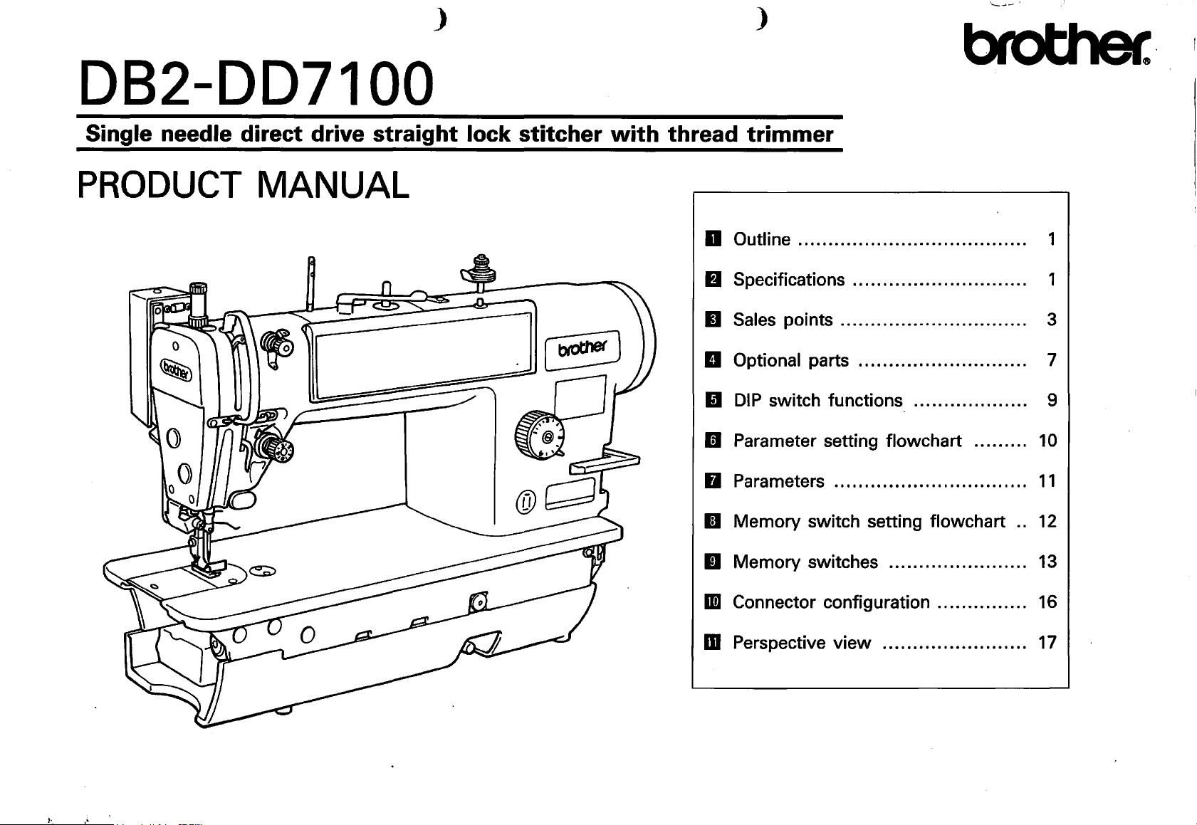
DB2-DD7100
Single needle direct drive straight lock stitcher with thread trimmer
,......_
____
'
PRODUCT
MANUAL
D Outline . . . . . . . . . . . . . . . . . . . . . . . . . . . . . . . . . . . . . . 1
II
Specifications . . ... . . . . . ... . . . .. . . . .. .. .. .. 1
II
Sales points . . . . . . . . . . . . . . . . . . . . . . . . . . . . . . . 3
II
Optional parts . . . . . . . . . . . . . . . . . . . . . . . . . . . . 7
II
DIP
switch functions ...... ... . . ... . . . . . 9
II
Parameter setting flowchart . . . . . . . . .
II
Parameters . . . . . . . . . . . . . . . . . . . . . . . . . . . . .. . .
II
Memory switch setting flowchart ..
II Memory switches . . . . . . . . . . . . . . . . . . . . . . .
1m
Connector configuration
...............
10
11
12
13
16
m Perspective view . . . . . . . . . . . . . . . . . . . . . .. .
17
Page 2
D Outline
•
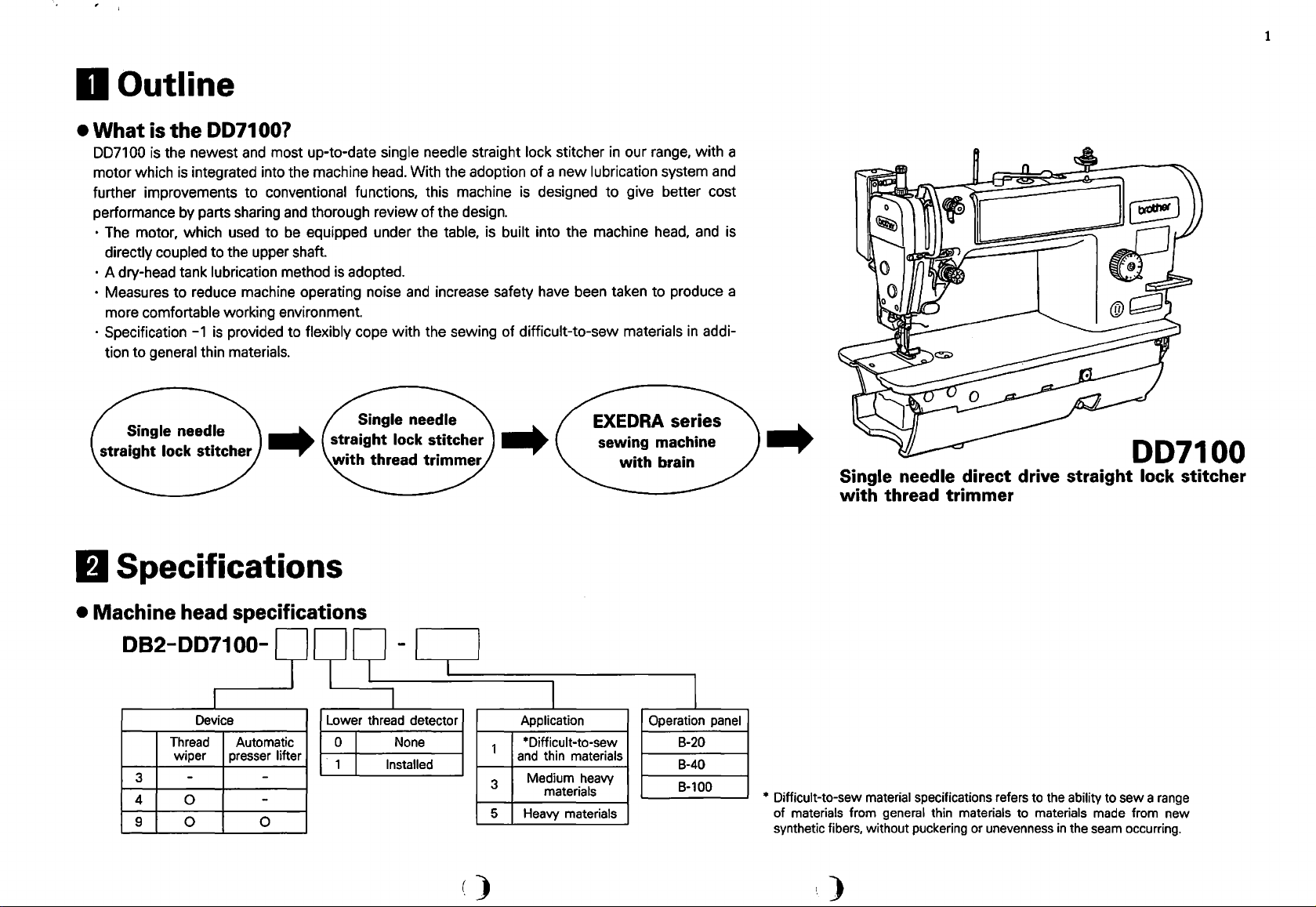
What
007100
motor which
further improvements to
performance by parts sharing and thorough review
• The motor, which used to
• A dry-head tank lubrication method is adopted.
• Measures
• Specification
is
the
DD71 00?
is
the newest
is
integrated into the machine head. With the adoption
directly coupled to the upper shaft.
to
reduce machine operating noise and increase safety have been taken to produce a
comfortable working environment.
more
-1
general thin materials.
tion to
and
most up-to-date single needle straight lock stitcher
conventional functions, this machine
be
equipped under the table, is built into the machine head,
is
provided to flexibly cope with the sewing of difficult-to-sew materials
of
the design.
of a new
is
designed
in
our range, with a
lubrication system and
to
give better cost
and
is
in
addi-
1
..
fJ
Specifications
•
Machine
082-007100-
head specifications
I
Device
Thread
wiper
3 -
4
9
0
0 0
Automatic
presser
-
-
9
99-l
Lower thread detector
lifter
o I
. 1 I
1
I
None
Installed
..
I
1
3
5
)
I
Application
*Difficult-to-sew
and
thin materials
Medium heavy
materials
Heavy materials
I
Operation panel
B-20
8-40
B-100
..
Single needle direct drive straight lock stitcher
with thread trimmer
• Difficult-to-sew material specifications refers to the ability to
of
materials from general thin materials to materials made from new
synthetic fibers, without puckering or unevenness
in
the seam occurring.
()
sew
007100
a range
Page 3
)
)
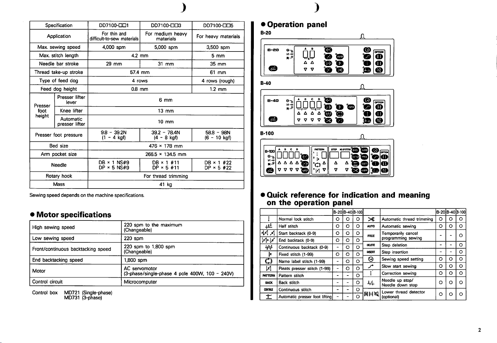
Specification DD7100-001
For
thin
Application
Max. sewing speed
Max. stitch length
Needle bar stroke
Thread take-up stroke
Type
of
feed dog
Feed dog height
Presser lifter
Presser
foot
height
Presser foot pressure
Arm pocket size
Rotary hook
Sewing speed depends on the machine specifications.
•
Motor
High sewing speed
Low sewing speed
Front/continuous backtacking speed
End
backtacking speed
Motor
Control circuit
Control box MD721 (Single-phase)
lever
Knee
Automatic
presser
Bed
size 476 x 178
Needle
Mass
specifications
MD731 (3-phase)
difficult-to-sew
lifter
lifter
9.8-
DB
DP
and
materials
4,000 spm
29
mm
39.2N
(1
- 4 kgf)
X 1 NS#9
X 5 NS#9
4.2
mm
57.4
4 rows 4 rows (rough)
0.8
mm
220 spm
(Changeable)
220 spm
220 spm
(Changeable)
1,800 spm
AC
servomotor
(3-phase/single-phase 4 pole 400W, 1 00 - 240V)
Microcomputer
DD7100-003
For medium heavy
materials
5,000 spm 3,500 spm
31
mm
mm
6
mm
13
mm
mm
10
39.2-
78.4N
(4
- 8 kgf)
mm
x 134.5
266.5
DB
DP
For thread trimming
41
to
the maximum
to
1 ,800 spm
mm
X 1 #11
X 5 #11
kg
For heavy materials
DD7100-005
5 mm
35
mm
61
mm
1.2
mm
58.8-
98N
(6
- 10 kgf)
DB
X 1
X 5
#22
#22
DP
• Operation panel
8·20
a-eo
e
e-a
Ill-<~
--...9
A B
OJJ
11 11
v v
•
••
••
••
B-40
B-40
e
B 100
-
A B C D FIGTEIIN
B-100
ea
DODD•
jll-cl
_....9
11111111.
vvvv.
e
• Quick reference
the
on
Normal lock stitch
!
.j.!.!.
Half stitch
A~B1
,a1
Start backtack (0-9)
~c1o,~a'
End
~,q,&
Continuous backtack (0-9)
Fixed
IE
Name label stitch (1-99)
CJ
Pleats presser stitch (1-99) -
!.e1
PlA1TERH
Pattern stitch -
BACK
Back
coma
Continuous stitch
Automatic presser foot lifting -
-
..!....
A B C D •
ea
jll-cl
_....9
O,OOEO•
11111111
v v
v
••
vee•
,.
D
2
~&
,o
11
.!.-1
v
operation
backtack (0-9)
stitch (1-99)
stitch -
••
STEP
IIUIFIIlliDI
oo
11
11
v
vcee
for
indication
panel
B-20 B-40
0 0 0
0 0 0
0 0 0
0
0
0 0
-
0 0 0
0 0
-
0 0
-
-
- -
-
D.
..,
·;
••
-·
D.
•m
-~
••
-·
D.
••
••
••
o•m
·;
••
--
and meaning
8-100
Automatic thread trimming
~
AUTO
Automatic sewing
Temporarily cancel
FJIEE
0
0
0
0
0
programming sewing
DELETE
Step deletion
II&Rf
Step insertion
Sewing speed setting
e
Slow start sewing
.r
Correction sewing
i
Needle up stop/
J.A.
Needle down stop
Lower thread detector
lill=t
lQ.
(optional)
B-20 B-40
0 0
0 0
- -
-
-
- -
0 0 0
0 0 0
0 0
0
0 0 0
0 0
0
B-100
0
0
0
0
0
2
Page 4
II
Sales points
3
Machine head
• The servomotor
eliminates the
without any losses.
minimum
(approximately
Pedal
---~
• Elimination of the V-belt also means that flakes from the belt
will
no
longer make the material dirty.
• Because the motor
on
the work table. Jobs such
winder have
much easier.
is
directly coupled to the upper shaft,
need
for a V-belt, motor power
In
so
that extensive energy savings
25%
compared to previous Brother models).
Warm-up time
is
built-in, it
also been eliminated,
with
addition, power consumption
4,000
5,000
is
no
as
installation
built-in
is
can
007100
spm
spm
longer necessary to mount a motor
so
that overall setting
96
ms
103 ms
of
belt covers
motor
and
transmitted directly
is
also kept to a
also be achieved
8737 Markll
and
up
because this
155
ms
189
ms
as
it
wears
a bobbin
has
become
•
The
motor
can
be
exchanged easily.
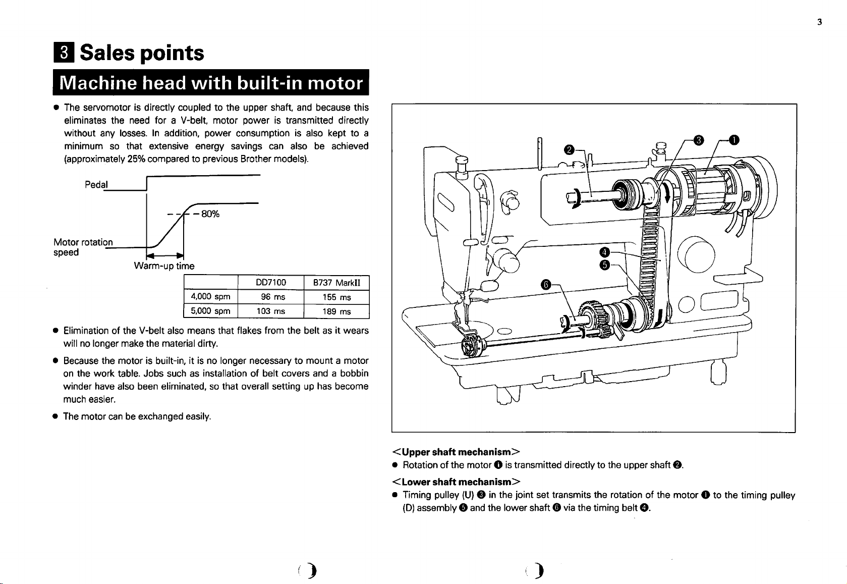
<Upper
• Rotation
<Lower
• Timing pulley
shaft mechanism>
of
the motor 0
shaft mechanism>
(D)
assembly 8
(U) 8 in
the joint set transmits the rotation
and
the lower shaft 0
is
transmitted directly to the upper shaft
of
via
the timing belt
8.
I,)
8.
the motor 0 to the timing pulley
Page 5
)
)
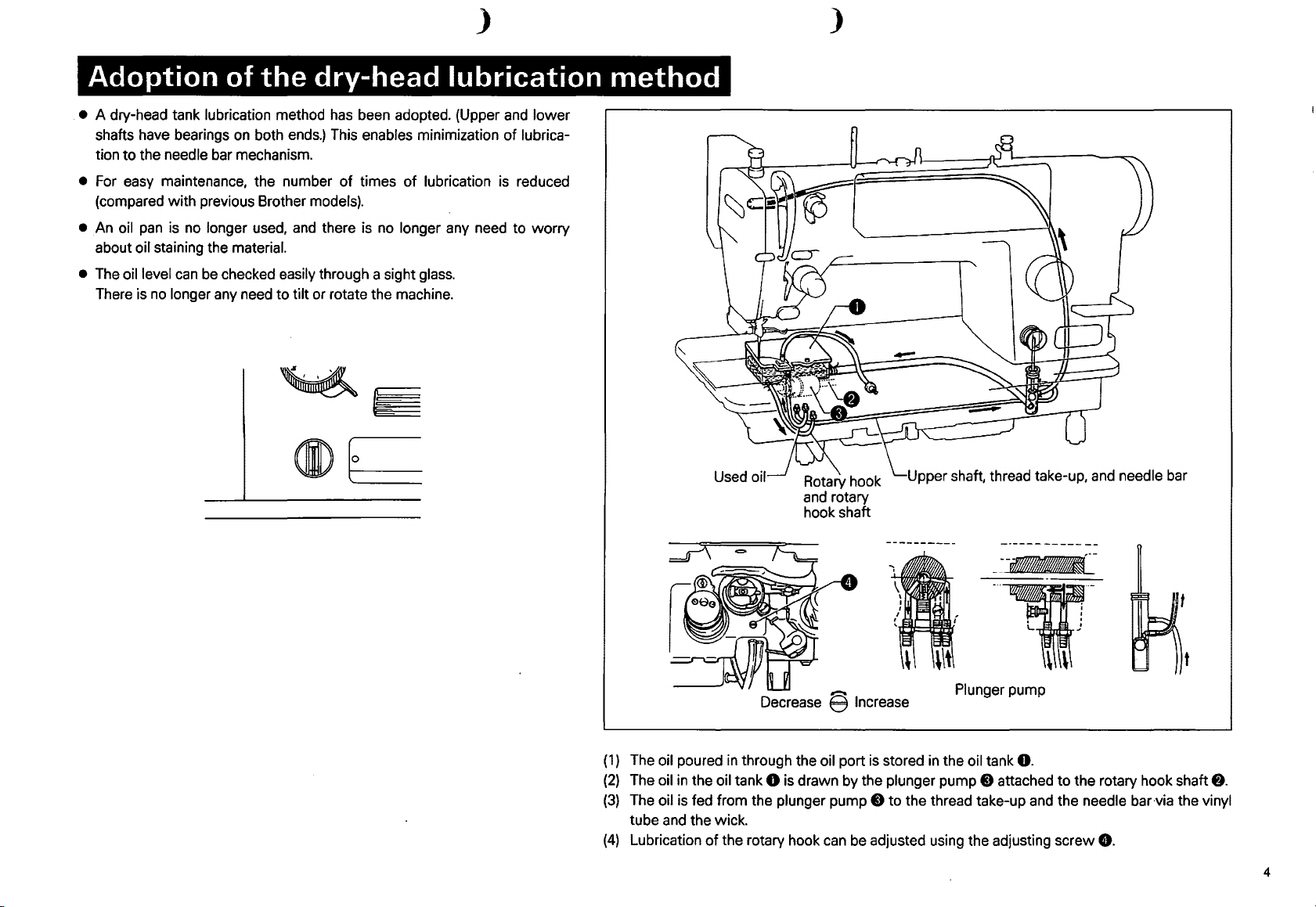
Adoption of
• A dry-head tank lubrication method has been adopted. (Upper and lower
shafts have bearings
tion
to
the needle bar mechanism.
• For easy maintenance, the number
(compared with previous Brother models).
•
An
oil
pan
is no longer used, and there is no longer any need to worry
about oil staining the material.
• The oil level
There is
can
be checked easily through a sight glass.
no
longer any need to tilt or rotate the machine.
the
on
both ends.) This enables minimization
dry-head lubrication
of
times
of
lubrication is reduced
of
lubrica-
method
Upper shaft, thread take-up, and needle bar
--~-
-·-1fi··-
. .
L J
\ \
Decrease § Increase
(1)
The oil poured
(2)
The oil
(3)
The oil is fed from the plunger pump 0 to the thread take-up and the needle bar via the vinyl
tube and the wick.
(4)
Lubrication
in
in
through the oil port is stored
the oil tank 0 is drawn by the plunger pump 0 attached
of
the rotary hook
can
be adjusted using the adjusting screw
Plunger pump
in
the oil tank
0.
to
the rotary hook shaft
0.
t
8.
4
Page 6
5
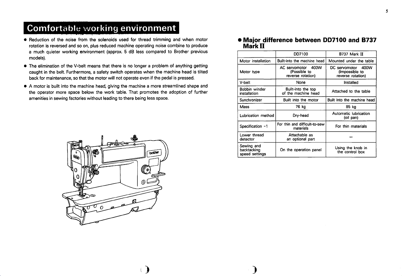
Comfortable
• Reduction of the noise from the solenoids used for thread trimming
rotation
a much quieter working environment (approx. 5 dB
is
reversed
and
vvorking
environment
and
so
on,
plus reduced machine operating noise combine to produce
less compared to Brother previous
when motor
models).
• The elimination of the V-belt means that there
caught
back for maintenance,
• A motor
in
the belt. Furthermore, a safety switch operates when the machine head is tilted
so
that the motor will not operate even if the pedal
is
built into the machine
head,
giving the machine a more streamlined shape
is
no
longer a problem
of
anything getting
is
pressed.
the operator more space below the work table. That promotes the adoption of further
amenities
in
sewing factories without leading to there being less space.
and
• Major difference between
Markll
DD7100
Motor
installation
Motor
type
V-belt
Bobbin winder
installation
Synchronizer
Mass
Lubrication method
Specification -1
Lower thread
detector
Sewing and
backtacking
speed settings
Built-into the machine
AC
servomotor
(Possible to
reverse rotation) reverse rotation)
None
Built-into the top
of
the machine head
Built into the motor Built into the machine
kg
76
Dry-head
For
thin
and
difficult-to-sew
materials
Attachable
an
optional part
On
the operation panel
head
400W
as
DD71
00 and 8737
B737 Mark
Mounted under the table
DC
servomotor 400W
(Impossible
Installed
Attached to the
85
kg
Automatic
For
lubrication
(oil
pan)
thin materials
-
Using the knob
the control box
II
to
table
head
in
)
)
Page 7

}
)
Flexible handling of even previously
• The focus
mechanisms such
high speed.
Needle bar stroke
Needle
Rotary hook For thin material Plastic race (lubrication not required)
Maximum sewing speed
*It is possible to attach a plastic race (lubrication not required).
• The special tool for measuring the presser foot pressure is no longer needed. A tension gauge set enabling easy measurement
and
of
machines with -1 specification is
as
the needle
(See
page
7.)
lower thread tensions is provided
bar,
DD71
on
sewing materials which are thin and difficult-to-sew. As a result
thread take-up, and rotary hook, materials which were previously difficult-to-sew
page
For
8.)
00-1 * for
materials specification
DB
as
difficult-to-sew
29.0
mm
X 1
#9
NS
4,000 spm 3,500 spm 4,000 spm
(In
this case, the maximum sewing speed is 3,500 spm.)
an
optional part.
(See
difficult-to-sew
new
synthetic materials specification
on the B737
31.0
mm
DB
X 1
#10
NS
materials
of
modification
can
be sewn at
B737-1 for thin materials
31.0
mm
DB
X 1
#11
For thin materials
of
Others
• The switches for
and check the current settings easily.
•
After thread trimming, the machine can be stopped with the needle at its highest position by reversing the motor. This is useful when
changing the
slow
start, correction stitch, and needle up/down stop position are provided
materials to be sewn, thick materials
in
particular.
(See
page
9.)
on
the operation panel so that you can
of
upper
s~t
• Gauge parts for the 8737
• A lower thread detector (optional part) is provided to indicate the remaining lower thread. This is useful when sewing a product that
allows
no
overlapping or incomplete stitching.
and
those for other manufacturer's
(See
page
7.)
can
be used.
6
Page 8

II
Optional parts
• Lower thread detector (183955-001)
The
lower
thread remaining will be displayed
thread detector will warn you that the thread has been all used up according
in
amount you set
issuing beep.
This is
Use the bobbin case
•
Set
*When the following part set is used on the machine, regularly set the sewing speed
useful when sewing a product that allows no overlapping or incomplete stitch-
ing.
for
new
advance by making the
assembly (525780-001) exclusive
synthetic fabric (for specification
as
% on the operation panel. The
lower
thread remaining indicator blink and a
to
the
DD71
00.
-3)
(18391 0-001)
lower
to
the
to
2,800 spm. (Max. 3,500 spm)
7
Adjusting
(S35781-001) li
Spring~
(S35783-001) m
Presser bar
pressure gauge
(S35782-001)
Presser
regulating
spring
(S35780-001)
Spring----~
(14751-001)
[For
screw~
ri
:--1
low
tension)
r--
Presser regulating
screw assembly
(S35779-001)
[with presser foot pressure indication]
Needle
DB
(S35775-31
[Plastic race:---..........._
lubrication
not required] r::'
Rotary hook
box assembly l }l 1
(535784-901)
r-------------------,
I
~Spring
I [For
: Spring (115188-001) :
1
I • I
L----
X 1 NS#10
0)
I
~
RP
~
C
~p:~.:~n
(S35788-001)
low
[For
""'->,,
..........
~
l
......
,}i\.'\Voef)V~.~~1
:...
..,
''
:~
I
.........
l,.,.,..,.'
......
' :
(100399-001) I
low
[For
low
~.::~
tension)
,.
l
..J
tension] I
tension]
1
I
•=m~y_j
Presser foot assembly
(S35777-001)
[For
low
friction]
~Screw
(S35786-001)
[without
lubrication hole)
When you change specifications -1 so
able
to
handle
following parts:
· Rotary hook
·Screw
(535786-001)
new
synthetic fabrics, use the
RP
box assembly (535784-901)
as
to
be
',)
)
Page 9

)
• Tension gauge set (183922-001)
This
is
a device designated for easy measurement
production is required, or the same thread tension is required on different machines.
of
upper and lower thread tensions. This is useful
when
frequent changing
)
of
threads and materials
to
be used for small-lot
Upper thread tension measurement
• Thread
wiper
set (183956-001)
• Presser foot lifting solenoid set
Presser foot lifting solenoid set A (with knee lifter) (183959-001)
Presser foot lifting solenoid set 8 (without knee lifter) (183960-001)
Lower thread tension measurement
8
Page 10

II
DIP switch functions
See
page
16,
"1!1
Connector configuration" for the
Presser foot position when the foot pedal
is
returned to the neutral position after
1
thread trimming
Setting of a delay from the time the
presser foot is turned
2
3
4
starts
Needle
rotation
(See
NOTE
up
stop position due to reverse
2.)
OFF
until the motor
5
Limited speed setting 1
6
7 Limited speed setting 2
8
DIP
switch position.
ON
OFF
ON
OFF
ON
OFF
ON
OFF
Presser foot
Presser foot is kept raised. (Japanese specification only)
(See
With delay
Without delay
The machine stops with the needle at its highest position
due to reverse rotation.
The machine stops with the needle at its highest position
without reverse rotation.
N.C
Maximum sewing speed (during high-speed sewing) that
can
Always set to off.
is
lowered. (Export specification)
NOTE
1.)
be
set through the operation
(See
NOTE
4.)
panel
(See
NOTE
3.)
(NOTE
(NOTE
(NOTE
(NOTE
1)
Once the knee lifter switch
the foot
the machine
to raise
2)
For
automatic presser foot lifter), be sure to set
3)
Limited sewing speeds depend
and 7 as
sewing speed
panel, it
If the setting
sewing speed
DIP
switch 6
OFF
ON
OFF
ON
4)
If
pedal
can
not
is
stopped; at this time, only the knee lifter is able
and
lower the presser foot.
-900 series specification machines (machines with
shown
in
is
is
actually limited to 4,700 spm.
DIP
switch 8 is set to
Be
sure to set it to off.
specified
of
memory switch 04 is changed to
is
not limited to
DIP
is
be
used to raise the presser foot while
the following table. When the maximum
as
4,
switch 7
OFF
OFF
ON
ON
on,
all
pedal operations are deactivated.
used to lower the presser foot,
an
on.
the set
on
settings for
5,000 spm
700 spm.
DIP
switch 2 to
DIP
switches 6
on
the operation
on.
Limited speed
3,500 spm
4,000 spm
4,500 spm
5,000 spm
9
Page 11

Parameter
setting
Start
flowchart
Set memory switch 01 to
Turn
off
ail
For
Leave the machine
* Press the thread trimming and AUTO keys. (The
LED of
LEDs.
the
B-1C0operation panel,
the
thread trimming key will blink, and a
parameter number
•
Select
the
and V keys below
Press
desired
other parameter setting
the
thread trimming key. (The value corre
ON.
*1
stopped
will
parameter
the
Change
r finish
select
after thread trimming.
appear on the ABdisplays.)
number
Bdisplay.
settina?
Change
pattern 1.
using
the
Finish
spending to the currently set parameter number
will
blink.)
Change
the
value
using
theAand7keys
below
theABdisplays.
*1: Refer to
A
the
memory
switch
setting
flowchart
The
data
currently
set
for
the
parameter
can be
checked only while the A key below the A dis
play is kept pressed. *2
*2:As to the data related to backtacking, press the A key to indicate the timing
angle
(*15*)
*3
Indicate
parameter
and V keys
Changing completely?
Further
number99using
below
the
B display.
changes
the
and v keyto
No
more
A
indicate
changes
a plusor
Indicate
minus
parameter
symbol.
number
90.
Related
will
blink.)
using
I'
to
theAkey
below
theBdisplay.
(Parameter
num
M
=
*3:As to backtacking information,the timing angle
*4:Select a plus < -/ > or minus symbol < — > for the value determined in
♦3.
backtacking?
Press the thread trimming key.(The plus or minus sym
bol
currently
Select
Press
ber
selected
the
plusorminus
the
thread
will reappear.)
symbol
trimming key.
Press
the
thread
trimming key.
End
("15*)
willappear.
10
Page 12

fi
Parameters
11
Parameter
10
11
13
14
15
16 12
17
18
20
21
22
23
24
26
27.
30
31
32
33
*
*
~
No.
15
05
30
36
00
10
40
02
05
50
10
07
03
05
-04
00
+02
-04
Default value
(150
ms)
(50
ms)
(300
ms)
(3
min.)
(30
ms)
(10s)
(40
stitches)
(20
ms)
(50
ms)
(50
ms)
(10
ms)
(7
ms)
(30
ms)
(0.5s)
(-60°)
(0°)
(30°)
(-60°)
Data
value setting range
00 -25
03
10
00 -60
00
10 -12
05
00 -99
01 -07
04
40 -70
05 -25
01 -15
00 -05
02 -50
-23
(On
plus are
-23
(On
plus
-23
(On
plus
-23 to
(On
plus are
(x1Q]
(0 -250
- 10 (x10]
- 90
- 60 (x2.5]
- 30
- 10
to
the
to +23
the
are
to
the
are
the panel, indications for minus
(30
(x1Q]
(100
(x5]
(5
sec.
(0
(5 -30s)
(0 -99
(x10]
(10 -70
(x1Q]
(40
(x10]
(40 -70
(x1]
(5 -25
(x1]
(1 -15
(x10]
(0 -50
(x0.1]
(0.2 -5.0s)
+23
(in
15°
panel,
indications for minus
" - "
and
(in
15°
panel,
indications for minus
" - "
and
+23
(in
15°
panel,
indications for minus
..
- "
and
+23
(in
15°
" -
II
and
ms)
- 100
- 900
- 5
- 150
ms)
stitches)
ms)
- 100
ms)
ms)
ms)
ms)
increments).
" -{
,.
increments)
II
-{
" respectively.)
increments)
II
-{
" respectively.)
increments)
II
-{
II
ms)
ms)
min.)
ms)
respectively.)
respectively.)
Function
Time delay from the time the machine starts to operate with the automatic presser foot raised to the time the motor
operates.
Time delay from the time the thread wiper turns
Time to keep the automatic presser foot lifter raised
The
presser foot signal will be automatically off after the set time
foot signal
Time from the presser foot lowering command to the presser foot
Constant voltage required to turn
Puller continuous
The
Time delay from the time the machine stops after thread trimming to the time the thread wiper operates
Thread wiper
Lower thread detecting
The
The
Time delay from the thread wiper
Time delay from the time when the machine stops with the needle at its highest/lowest position to the lower thread
detecting
and
Quick reverse device ON-timing
and
Quick reverse device OFF-timing
and
Quick reverse device OFF-timing upon
and
The
is
not automatically off.
on
the presser foot after the presser foot lowering command
ON
time
number of stitches to
ON
time
first
ON
time of the lower thread detecting
first
OFF
time of the lower thread detecting pin
pin
ON
(Lower thread detection function at the needle up/down stop with the foot pedal
second ON-timing for the quick reverse device upon double
be
produced from the start of sewing until the puller lowers
pin
ON
control time
OFF
to the lower thread detecting
upon
start or continuous backtacking
upon
start
end
OFF
until the automatic presser foot turns
(in
all
blocks)
pin
and
continuous backtacking
backtacking
passes.
ON
pin
end
backtacking
When the data
once
ON
is
ON
set to
00,
in
the presser
neutral)
The
parameter numbers appear
(NOTES)
*:
The
timer-off function for the presser foot is activated only when memory switch 36 is set to off.
*:
This parameter is available only when memory switch 35
+:The
lower thread detection function for the needle up/down stop when the pedal
~:
This parameter is available only when memory switch
on
the
panel.
22
is
set to
is set to
on.
on.
is
positioned at neutral
is
activated only when memory switch
51
is set to
on.
Page 13

)
II
Memory switch setting flowchart
• Leave the machine stopped after thread trimming.
• Turn
off
all
LEOs
(For the
· Press the needle up/down stop key while pressing the thread trimming key.
(A
needle
8-1
8-1
memory switch number will appear on the
up/down
00 operation panel, the setting will be indicated
(except for the
00 operation panel, select pattern
stop key will be lit to indicate the direction
LED
of
the needle
1.)
A8
up/down
displays,
on
the D display.)
stop
and
of
either
movement.
key).
of
the
two
On
LEOs
of
the 8-40
)
the
---------· ............................... ------------,
or
·----------··------------Y
• Select
•
~------------------------------------------------------------~------------------------------------------------------------~
Change
the desired memory switch number using the
Press the needle up/down stop key
of
the
two
LEOs
of
(Either
operation panel, the
the needle
1::..
and
v keys below the D display can be used instead.)
to
1::..
change the setting
up/down
stop key will be
and v keys below the
of
the memory switch.
lit
On
the 8-40
A8
displays.
or
8-100
...............
Indication when memory switch
is
set
to
off
~
~@
~
Indication when memory switch
is set to on
....................... .
D
and
I
@I
.aD
D
~@and
'V
~
· Keep pressing the thread trimming key at least for 1 second
(All
LEOs
(NOTE)
except for the
If the power is turned
renewed.
LED
of
the needle up/down stop key will be turned off.)
off
before the end operation, memory switch settings are not
to
cause a beep to be issued.
12
Page 14

II
Memory switches
13
Memory switches
01
Parameter setting
Interlocking along with
02
forward step
Power supply drop
03
check
04
Limited sewing speed
Needle penetration force
05
06
07
08
(NOTE
1)
When the power
is
01
turned
- 08
Parameter setting
ON
OFF
Parameter setting change
Forward step
ON
(for thread trimming).
Forward step
OFF
(for thread trimming).
Power supply drop check (reset detection)
ON
function
OFF
Without the above-mentioned function
The
ON
(See
Maximum sewing speed
OFF
Needle penetration force
ON
OFF
Needle penetration force
ON
OFF
ON
OFF
ON
OFF
on
again,
is
same
NOTE
sewing speed
can
be
is
possible during backward step
is
impossible during backward step
activated.
as
settings of
1.)
can
DIP
is
is
is
be set
changed.
is
prohibited.
switches 6
limited to 4,700 spm.
strong.
ordinary.
up
to 5,000 spm.
and
7.
Memory switches
Thread trimming
11
thread wiper output
Presser foot position
after thread trimming
12
(See
NOTE
Presser foot position
after the machine stops
13
with the pedal
14 Actuator switch
15 Slowdown stop control
Lower thread remaining
16
detection
17
Half-stitch correction
Reverse stitch correction
18
2.)
and
in
neutral
11
- 18
ON
Without thread trimming
OFF
With thread trimming
Presser foot
ON
neutral.
Presser foot is lowered when the foot pedal is in
OFF
neutral.
ON
Presser foot
Presser foot is at its lowest position.
OFF
It
is
ON
OFF
ON
OFF
ON
OFF
ON
OFF
ON
OFF
used
It
is
used
Ordinary slowdown stop
Slowdown
tion
Unable to
Able to be
A forward stitch or half stitch
(See
A forward stitch
cannot
A forward stitch or reverse stitch
rected.
A forward stitch
cannot
is
raised when the foot pedal
is
at its highest position.
as
the thread trimming switch.
as
the reverse
and
stop control with 1
be
used.
used.
NOTE
3.)
be
(See
be
can
corrected.
NOTE
can
corrected.
and
thread wiper
and
thread wiper
and
correction switches.
and
control
can
be
corrected. A half stitch
(See
NOTE
3.)
3.)
be
corrected. A reverse stitch
(See
NOTE
3.)
is
stitch elimina-
be
corrected.
can
be
cor-
in
(NOTE
2)
It
(NOTE
3) A forward stitch
stitch or reverse stitch
lit.
is
activated when
()
DIP
switch 1
can
be
corrected when the
can
be corrected when the
is
set to
on.
LED
of the correction switch
LED
of the correction switch is not
is
lit. A half
Page 15

)
)
Memory switches
Double start backtacking
21
Double end backtacking
22
Number
start backtacking plus 1 0
23
stitches
Number of stitches for
end backtacking plus 1
24
stitches
Feed
start backtacking is com-
25
pleted
Start end backtacking
26
Continuous backtacking
27
setting
Number
continuous backtacking
28
plus 1 0 stitches
of
stitches for
direction when the
of
stitches for
0
21
- 28
Start backtacking
ON
lengths A,
Start backtacking
OFF
lengths A and
End
backtacking is performed
lengths
ON
B-20 operation panel).
End
lengths C and D
OFF
panel).
Extra
ON
stitches set for both lengths A
No extra stitches are added.
OFF
Extra 1
stitches set for both lengths C
ON
on
No
OFF
The
ON
remaining
The machine
OFF
normal.
End
ON
down.
The machine
to start low speed sewing, then shift to end back-
OFF
tacking.
Forward stitching for the number of stitches set
in
number
ON
performed repeatedly for the number
set
Continuous stitching will be performed for lengths
OFF
A,
Extra
ON
C,
No
OFF
C,
backtacking
1 0 stitches are added to the number
0 stitches are added to the number
the B-20 operation panel).
extra stitches are added.
machine will stop with the reverse feed
backtacking will start without speed slowing
the A display, and backward stitching for the
of
in
the D display.
B,
C,
and D
1 0 stitches are added
and
D.
extra stitches are added.
is
B,
D,
on.
stitches set
performed
A,
then
B.
is
performed
B.
C,
and D
is
performed
(B
and A
will stop after feed
will slow the sewing speed gradually
(The
as
specified
in
the order
in
the order
in
(B,
in
the order
A,
B,
and A
in
the order
on
the B-20 operation
and
and D (B
is
the 8 display will
C display will
in
the
to
each lengths A,
on
the
B.
and
returned to
of
times
be
ABCD
displays.
of
of
of
of
of
of
A
be
blank.)
B,
Memory switches
Start backtacking suspensian by foot pedal being
placed
in
31
backtacking speed
change during the start
backtacking
The number
32
stitches
B-40 operation panel
Pleats presser stitching
33
direction
-
34
Presser foot soft drop
35
function
Presser foot timer-off
36
function
37
38
(NOTE
4)
(NOTE
5)
(NOTE
6)
(NOTE
7)
neutral or
of
backtack
on
the B-20 or
For
the B-40 operation panel, the number
fixed stitching or pleats presser sewing.
This setting depends
to
00,
the machine response will
This setting depends
to 1
0,
the machine response will
Timer-off function
is
31
- 38
Sewing can be suspended by returning the foot
pedal to neutral. During start backtacking, sewing
ON
speed depends
Sewing
foot pedal to neutral. During start backtacking,
OFF
sewing speed is fixed regardless
pedal stroke.
The number
ing, label attaching, or pleats presser sewing can
ON
be
The
(for fixed stitching, label attaching, and pleats
OFF
presser sewing).
Without reverse stitching (Fixed stitching will be
ON
called
With reverse stitching (Ordinary pleats presser
OFF
stitching)
-
ON
-
OFF
Manual soft drop function
ON
Automatic soft drop function
OFF
Timer-off function
ON
will not be lowered by timer.)
Timer-off function
OFF
ON
OFF
ON
OFF
on
the setting
on
not activated when parameter No.14 is set to
be
the setting
be
can
changed.
number
back.)
of
parameter No.15. When parameter No.15
the fastest but with noisy operating sounds.
of
parameter No.16. When parameter No.16
the fastest but with noisy operating sounds.
on
the foot pedal stroke.
not
be
suspended by returning the
of
backtack stitches for fixed stitch-
of
backtack stitches
(See
NOTE
4.)
(See
is
not activated. (Presser foot
is
activated.
of
end backtack stitches
NOTE
(See
(See
00.
of
is
NOTE
can
the foot
fixed to 4
5.)
6.)
NOTE
7.)
be changed for
is
set
is
set
14
Page 16

15
Memory switches
Mode after lower thread
41
alarm
Rotary hook
42 the lower thread
detector
43
(See
44
(See
Delayed start of standing
45
operation
Emergency stop
presser lifter pedal
46
during standing
operation
Emergency stop using
variable speed pedal
47
during standing
operation
Lifting the presser foot
using thread trimming
48
pedal during standing
operation
Memory switch
Puller output selection
61
(lifting/lowering the
I I
NOTE
NOTE
used
8.)
8.)
with
by
61
puller)
41
- 48
Foot pedal
ON
After lower thread alarm, the foot pedal operation
OFF
is deactivated until the cancel key is pressed.
1.7-time rotary hook
ON
Standard rotary hook
OFF
-
ON
Be
OFF
ON
OFF
ON
OFF
ON
OFF
ON
OFF
ON
OFF
ON
1--0-F-F-+-P-u-lle_r_o_u_t_pu-t---------------11
sure to set to off.
-
Be
sure to set to off.
Without any delay.
With a delay (for 80
Impossible to make
presser lifter pedal
During automatic sewing, emergency stop
performed using presser lifter
Impossible to make
variable speed pedal
During automatic sewing, emergency stop
performed using variable speed
It
is
pedal is used.
It
is
Synchronizer signal output I
can
be used after lower thread alarm.
ms).
an
emergency stop using
pedal.
an
emergency stop using
pedal.
always deactivated after the presser lifter
activated.
can
can
be
be
Memory switches
Lower thread detection
after the machine
stopped by putting foot
51
52
53
54
55
56
57
58
(NOTE
(NOTE
in
pedal
(See
Needle up/down stop
key operation
8)
9)
neutral
NOTE
Do
not change these settings.
The
time for delay
ward within the time, lower thread
This function
is
9.)
can
is
available for sewing process without thread trimming.
51
OFF
be
- 58
is
Lower thread
stopped by putting foot pedal
ON
specified time.
Lower thread is not detected after the machine
OFF
stopped
Needle up/down stop key operation
ON
(Needle stop position cannot
OFF
Needle up/down stop key operation is activated.
ON
OFF
ON
OFF
ON
OFF
ON
ON
OFF
ON
OFF
changed
in
parameter
will not detected.
detected while the machine is
by
putting foot pedal
be
No.
27.
If the foot pedal
The
default delay
in
in
neutral for the
neutral.
is
deactivated.
changed.)
is
pushed for-
is
0.5
seconds.
is
Page 17

1m
Connector configuration
)
)
CN7
6j@oooo§Jj1
z 0
Nrn
0
~
...,.
~~
z
~
0 0
~m
0
0
r-..
z 0
wm
0
~
...,.
~~~~ansformer
seconda~
co11
11
CNS
DSW
1
8
~ooooooooo§Jj
FVR
1
~1!!!!!!!!1
CN9
ljo
o ol3
(I
I
FUSE2
ToCNS
l.liii
[]
IJML7
1
AC201V[]D.
D:f-1{
/NOD
AC20V
ID
AC20V
0
20
AC
~L_
______
1.
Connectors
2.
Connector
are
illustratec:t
positions
as
are
different from
CNS
0000000000
19
0000000000
20
(X)-
...,.
-
z
Lt')
0
-CD
FUSE1
11o
(Power)
SA
o o
o14
CNM
Ground
u
v
w
...,. N
CN1
(Motor)
g
SA
ToCN7
6
~
I
0
0
z
,\
.,..
....
'*"
(/)
6V20W
TMI
2 1
- 0
z 0
om
0 :
CND
1
Ground
1XXV
2
3
1XXV
4
2XXV
2XXV
5
2XXV
6
I
-411
r---......::<=::::5~
CJ.......!:Q=~;;;;:>
viewed from the
actual
To
the transformer primary
pin
side.
ones.
CND
coil
1
2
3
4
5
6
7
8
9
10
11
12
13
14
15
16
17
18
19
20
1
2
3
4
5
6
7
8
9
10
11
12
13
14
15
CN1
(Transformer) (Forward step)
AC10V
AC10V
AC30V
AC30V
CN10 CN12
External
power
supply
DC+12V
DC+5V
sov
ov
+40V
(E1)
CN2
DC+8V
DC+5V
Forward
sov
(Presser
ov
Presser
Presser
Presser
step
power
switch
output
input
foot)
CN3 CN4 CN5
(Standing
DC+8V
High
speed
Thread
trimming
sov
Low
speed
Presser
Variable
operation)
switch
switch
foot
speed
switch
switch
input
(Detector)
F.
G
N.C
N.
C
N.C
sov
ENCA
ENCB
u B
v
w D
Needle
down E
Needle
up
DC+5V
N.
C
N.
C
N.C
CN13 CN14
(Machine)
F.
G
N.
C
Thread
trimmer
Thread
wiper
Quick
reverse
ov
OV
N.·c
N.C
Tlvead
trirming
Thread
wiper
Quick
reverse
Quick
reverse
Safety switch
power
power
power
output
output
output
swi1ch
(lower
thread)
F.
G Puller output
N.
C
Sensor
input
Lower
thread
power
DC+8V
sov
DC+5V
Lower
thread
output
(Panel)
DC+5V
sov
KEYO
KEY1
KEY2
oc
A
c
(LEDO)
F
(LED1)
G
(LED2)
PLED
DC+8V
SEN
BUZZ
N.
C
N.C
N.
C
CN15
(Puller)
N.
C
N.
C
N.C
N.
C
Puller
N.
C
N.
C
N.
C
N.
C
(STB)
power
CN6
(VR/Bobbin
DC+5V
VR
(Bobbin
Bobbin
output
sov
TM1
(lamp)
AC6V
AC6V
changer)
input)
CN9
(Transformer)
AC6V
N.
C
AC6V
16
Page 18

1D
Perspective
view
17
Page 19

r
""(:---
r.
I
(
r----
----
-
·~·
.,
,
......
.
()
.....
·,
:-·:
~
BROTHER
~rinteci
INDUSTRIES,
in Japan
LTD.
NAGOYA,
JAPAN
117-510
160506888
1996. 05.
<D
 Loading...