

Page 1
SERVICE
FOR
082-8797
082-8798
MANUAL
SINGLE NEEDLE ADJUSTABLE
BOTTOM
FEED
LOCK STITCH MACHNE
. .
~
TOP
·
'
AND
Page 2
CONTENTS
I
SPECIFICATIONS,........................................................
I
MECHANICAL
II)
Upper shaft and needle bar mechanism . . . . . . . . . . . . . . . . . . . . . . . . . . 3
IZ]Lower shaft and rotary
~Upper
II]
Presser
I
STANDARD
DESCRIPTIONS
I·.
. . . . . . . . . . . . . . . . . . . . . . . . . . . . . . . . . . . . . . . . . . 3
hook
mechanism . . . . . . . . . . . . . . . . . . . . . . . . . 4
feed mechanism . . . . . . . . . . . . . . . . . . . . . . . . . . . . . . . . . . . . . . . • . 5
foot
mechanism . . . . . . . . . . . . . . . . . . . . . . . . . . • . . . . . . . . . . . . . . 6
ADJUSTMENT
I·.............................................. 7
1
IIJAdjusting feed
IZ]Adjusting
~Adjusting
IIJAdjusting feed
rn:JAdjusting
II)Synchronizer
[l]Replacing
'OTHER,
[!]Sewing
IZ1Sewing
~Attaching
IIJAttaching material end sensor . . . . . . . . . . . . . . . . . . . • . . . • . . . . . . . . . . 14
timing
timing
presser
dog
feeding
<Alternative
<Feeding
<Adjusting
<Adjusting
foot
feeding
feeding
{082-8798)
fixed and movable knives
between needle and rotary hook . . . . . . . . . . . . . . . . 7
foot
foot
up and
and presser
. . . . . . . . . . . . . . . . . . . . . . . . . . . . . . . . . . . . . . . . . . 7
height
height
and presser
down
foot
foot
. . . . . . • . • . . . . . . . . . . . . . . . . . . . • . . . • . . . . . • 10
. . . . . . . . . . . . . . . . . . . . . . . . . . . . . . . . . . . 8
. . . . . . . . . . . . . . . . . . . . . . . . . . . . . . . . . . . . . . 8
foot
movement
foot
height>
front
and rear
feed>
{082-8798)
. . . . . . . . . . . . . . . . . . . . . . . . . . 9
of
feeding and presser
. 0
0. 0 ••••••••
position>
....
0
••••
0 0
....... .-.......................................................
with
synthetic thread . . . . . . . . . . . . . . . . . . . . . . . . . . . . . . . . . .
with
vi nylon thread . . . . . . . . . . . . . . . . . . . . . . . . . . . . . . . . . . . .
presser
foot
lifter
set . . . • . . . . . . . . . . . . . . . . . . . . . . . . . . .
foot>
0
••
0. 0 0...
0
•••
0
•••••
••••••
0
•••
0
•••••
. . . . . . . . . . . . • . . . . .
9
9
0...
0 • • • • 9
9
11
12
12
12
13
Page 3
I
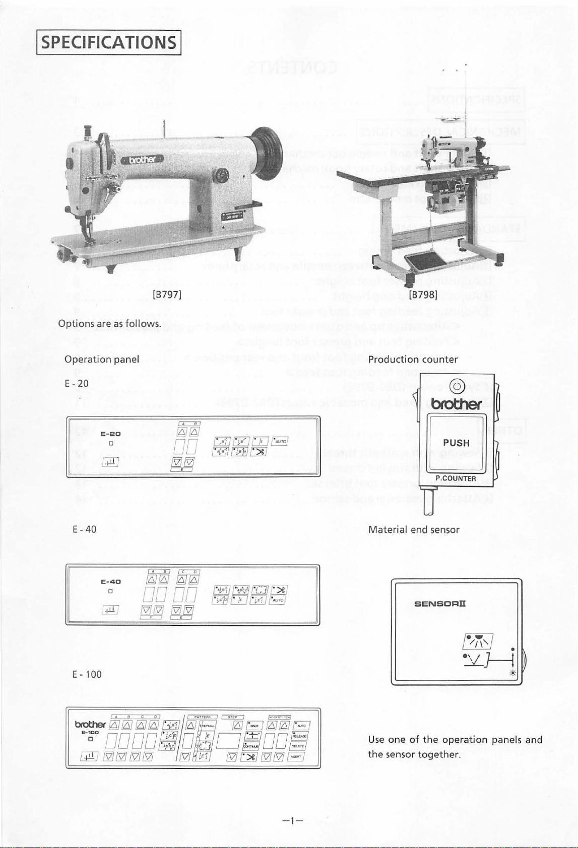
SPECIFICATIONS
[B
797]
I
[B798]
Options are
Operation panel
E- 20
E-
40
E-20
E -
as
0
40
0
follows.
Production counter
@
brother
EJ
P.COUNTER
Material end sensor
SENSORll
E-
100
-1
-
Us
e one
of
the sensor t
the
operation
ogether
panels and
.
Page 4
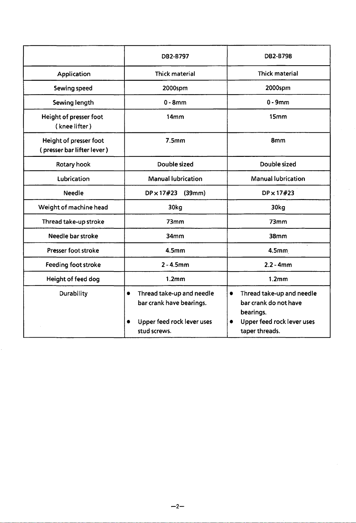
DB2-B797
DB2-B798
Application
Sewing speed
Sewing
Height
(knee
Height
(presser bar
Rotary hook
Weight
Thread take-up stroke 73mm 73mm
Needle bar stroke
Presser
length
of
presser
of
presser
Lubrication
Needle
of
machine head 30kg 30kg
foot
foot
lifter)
foot
lifter
lever)
stroke 4.5mm 4.5mm
Thick material
2000spm
0-Smm
14mm
7.5mm
Double sized
Manual lubrication
DPx
17#23
(39mm)
34mm
Thick material
2000spm
0-9mm
15mm
Smm
Double sized
Manual lubrication
DPx
17#23
38mm
Feeding
Height
Durability
foot
of
feed dog
stroke
2-4.5mm
1.2mm
Thread take-up and needle
•
bar crank have bearings. bar crank
Upper feed rock lever
•
stud screws.
uses
Thread take-up and needle
•
bearings.
Upper feed rock lever
•
taper
2.2-4mm
1.2mm
do
threads.
not
have
uses
-2-
Page 5
I MECHANICAL
[II
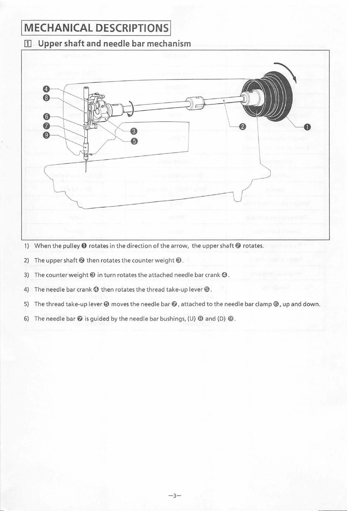
Upper shaft and needle bar mechanism
DESCRIPTIONS!
1)
When
2)
The
3)
The counter
4)
The needle bar crank e
5)
The thread
6)
The needle bar
the
pulley 0 rotates
upper
shaft@
weight@
take-up
then
rotates
in
then
lever 0 moves
f)
is
guided by
in
turn
the
direction
the
counter
rotates
rotates
the
the
needle bar bushings, (U) @ and
ofthe
the
attached needle bar crank e.
the
thread take-
needle
arrow,
weight@.
bar
f),
up
attached
the
lever
upper
0.
to
the
shaft@
needle bar clamp
(D)
rotates.
@.
0,
up
and
down.
- 3-
Page 6
~
lower
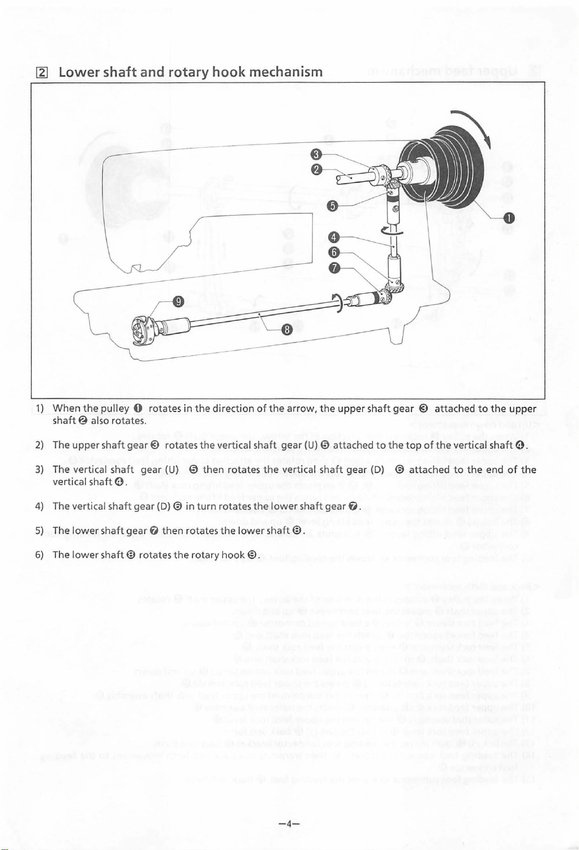
shaft and rotary hook mechanism
1)
When
shaft@
2)
The
upper
3)
The vertical sha
vertical
4)
The vertical
5)
The
lower
6)
The l
ower
the
also
shaft
pulley 0
rotates
shaft
gear@
ft
e.
shaft
gear
shaft
gear
shaft@
rotates
.
rotates
gear
(U)
(D)@ in
f)
then rotates
rotates
the
in
the
0
turn
rotary
direction
the
vertical sha
then
rotates
the
hook@.
rotates
the
lower
of
the
ft
the
lower
shaft@.
arrow,
gear
vertical
the
(U) 0 attached
shaft
shaft
upper
gear
gear
f).
shaft
gear @ attached
to
the
top
(D)
@
attached
of
the
to
vertical
to
the
the
shaft
end
upper
e.
of
the
-4-
Page 7

@]
Upper
feed
mechanism
<Up
and
down
movement>
1)
When
the
pulley 0 rotates in
2)
The upper
3)
The upper feed
4)
The upper
5)
The upper feed
6)
The upper feed
7)
The upper feed
8)
The
9)
The upper feed
connector®.
10)
The feeding
<Back
and
1)
When
2)
The upper
3)
The feed cam sleeve@ moves
4)
The feed
5)
The feed rock
6)
The feed roc k
7)
The feed rock
8)
The upper feed rock connector
9)
The upper feed rock arm
1
0)
The upper feed rock shaft
11)
The
12)
The
13)
The
14)
The
foot
15)
The feeding
shaft@
lifting
link
{L)@ moves
foot
forth
movement>
the
pulley
shaft@
forked
shaft
shaft @ in
shaft
roller
stud assembly@
upperfeed
link
(S)@
then
feeding
connector®.
foot
foot
rotates
lifting
feed connector 0 pivots
lifting
lifting
lifting
lifting
connector®
0 rotates in
moves
connector
arm
arm®
rock lev
moves
connector bracket
connector®
the
direction
the
upper feed li
eccentric
rock arm
rock
rock arm
the
upper
lever @ transmits an up-and-down
ill
turn
(R)
er@
wheel@
(R) 0 then
shaft@
the
ill
then
moves
®then
assembly®
then
moves
the
in
f)
moves
feed
moves
the
direction
feed
cam
the
feed
pivots
pivots
pivots
the
{L)
(f) pivots
pivots
the
feeding
moves
lifting
the
the
pivots
of
the
arrow,
fting
eccentric
then
rotates
the
upper
pivots
turn
pivots
the
link
lever@
the
feeding
ofthe
sleeve@ up and
forked
the
upper feed rock connector
pivots
the
lin
foot
a>
the
connector
feed rock shaft arm ill.
feed rock shaft
feed rock shaft arm
the
upper
the
point
the
upper feed rock
k {S)@ back and
connector bracket
then
transmits this back-and-f
feeding
the
feed
the
upper feed
the
upper feed
(L)@ back and
up
and
foot
ID
arrow,
feed rock arm
of
the
roller
stud assembly@.
foot
ID
the
upper
wheel@.
attached
lifting
down.
up and
the
upper
down.
ill
up
@.
®.
upper
lever@.
forth.
a>
back and
shaft@
upper
lift
rock arm
lifting
lifting
forth.
movement
down.
and down.
{L)
feed rock shaft
back and
rock
rock arm
shaft@
(f)
up
and
{R)
®.
orth
forth.
(R)
rotates.
ing feed connector 0 .
0.
shaft@.
f).
to
the
attached
rotates.
down.
assembly®.
forth.
movement
feeding
to
the
foot
feeding
-5-
Page 8

[!]
Presser
foot
mechanism
1)
When
the
2)
The
upper
3)
The
upp
er feed
4)
The
upper
5)
The
upper
6)
The
upper
7) The
8)
9)
1 0) The presser
11)
upper
The
link
(L)@
The
upper
The presser bar
pulley 0 rotates
shaft@
liftin
feed
feed
feed
feed
foot
rotates the
lifting
g feed connector e pivots
lifting
lifting
lifting
then
moves
lifting
bar
bracket®
ID
moves
in
the
eccentric
rock arm
rock
shaft@
rock arm
the
lever@
the
presser
upper
direction
wheel@
(R) 0 then
in
f)
moves
upper feed
in
turn
then transmits this back-and-
feed
turn
moves
foot
of
the
lifting
the
@ up and
eccentric
then
rotates
the
upper
pivots
the
pivots
the
link
lifting
lever@ back and
the
presser
arrow,
(L)@ back and
it rotat
the
feed
upper feed
upper feed li
foot
down
es
wheel@.
attached
lifting
.
forth.
bar
forth
rock arm
lifting
bracket®
the
upper
upper
(R)
rock
fting
rock arm
forth.
movement
shaft@.
lifting
feed connector e.
0.
shaft@
f).
back and
to
the
.
forth.
presser bar
ID.
-
6-
Page 9

I
STANDARD
ADJUSTMENT
lil Adjusting feed timing
I
penetration
1.
4
........
Smm
5.
Smm
6
mm
1)
Turn the pulley
2)
Loosen
3)
Loosen
turning the feed
~
<Needle bar rise>
the screw and detach the rear plate.
the
Adjusting timing between needle and rotary hook
to
make the feed dog even
two
screws
cam
0.
@ in the direction
with
the needle plate
Adjust the needle penetration
of
the arrow.
Rotate the pulley toward yourself and align
rotary hook point 0
the needle
or
I 0. I
mm
less
•
•
NOTE: When using
Loosen
point
At
this time,
the gap between the rotary hook
the
needle@
top
surface.
to
4-6mm shown in the figure above by
with
needle center @ when
is
raised
the screw
0
with
2.2
mm
from its lowest position.
@).
Align the rotary hook
the needle center@.
secure
the rotary hook 0
is
less
than
0.1
vi
nylon thread,
mm.
see
point
P.12.
the
so
that
0 and
-7-
Page 10

<Needle bar
height>
0.5--l.Smm
~
Adjusting presser
foot
height
Adjust
and rotary hook
rotary hook
center@.
•
The
raised using the presser
1)
2)
3)
the
gap between the
point 0 to
point
Loosen
up and
standard presser 0 rise
Loosen
the
@.
Put a 7.5 mm gauge
the presser
Loosen
0 up and
the screw
down
the presser adjusting screw
presser
the screw 0 and move the presser
down
0
to
adjust
foot
0 using the presser
foot
0.
to
top
of
the needle
0.5-1.5 mm when the
is
aligned
@).
Move the needle bar 0
the
foot
lifter@.
or
something similar under
adjust.
with
the
gap.
is
7.5 mm when
@)
foot
eye
needle
it
is
and raise
lifter
foot
[!]
Adjusting feed dog height
-8-
The
standard feed dog 0 height from the needle
plate
top
at
its maximum.
•
Loosen
@)
up and
surface
the
screw@.
down
is
1.2
mm when the stitch length
Move
the
feed ·lifting arm
to
adjust.
is
Page 11

~
Adjusting feeding
foot
and presser
foot
<Alternative
up and
down
movement
left
JMJ'l
<Feeding
-------=-==--
same
height
foot
and presser
foot
height>
of
feeding and presser
foot>
The
feeding
and down
The
feeding
equal or slightly lower than
highest position.
1)
Lower the presser
thread take-up
2)
Loosen
lifting
When moved
When moved
The
standard height range
• Loosen
appropriate
upper
down.
Maximum height . . . . . 4.5
Minimum height . . . . . 2 mm
foot
0 and presser
alternately.
foot
the
rock arm 0
the
lifting
0 height position should be
is
screw 0 .Move
right
left
nut
to
the
feed connector shaft 6 up and
foot
at
its highest position.
right
and left.
. . . .
. . . . .
is
2-4.5
@)
and adjust
material by
mm
foot
@ move up
the
presser
lifter
Presser
to
Presser
@)
while
the
upper feed
foot
rises
the feeding foot.
foot
descends.
mm.
the
moving
foot
the
even
heights
the
@
2-4.5mm
<Adjusting
<Adjusting
feeding
feeding
foot
foot
front
feed>
and rear
position>
The
feeding
feed
dog@
•
Loosen
shaft
The
feeding
feed dog 0 feed.
•
The
conditions.
•
Loosen
and down
foot 0 end
end.
the screw
assembly«!)
foot
feeding
the
nut
to
should
@).
to
adjust.
@ feed should
foot
feed
Q). Move the roller stud
adjust it.
be
aligned
Turn the upper feed rock
be
can
be
changed
with
equal
to
to
4D
the
the
suit
up
-9-
Page 12

[§]
Synchronizer (082-8798)
21--23mm
.The
synchronizer detects
ICs.
Also,the synchronizer controls needle lowest
position signal and thread
one hole
The
and screw bottom
needle
between the
needle
stopped
Be
IC.
distance between the needle plate
should
is
at
its lowest position. Also,the distance
needle plate
tip
is
12-13
mm when
at
the needle highest position.
sure
to
turn
off
the
the
needle
trimming
be
21-23
top
surface and
the
power when adjusting.
with
top
mm
when the
machine
two
signal
surface
the
is
hole
with
<Adjusting needle thread trimming signal sensor
position>
1)
2)
NOTE:
Turn
the
pulley
operation
from its
If
the hole
@ bottom, loosen the screw e and move
hole
Move the hole
operation
position.
Move the
direction
to
lowest position.
IC@
IC@
to
adjust it.
to
in
the
direction
raise the needle bar 0
is
not
aligned
IC@
to
raise the needle bar 0 highest
hole
IC@
lower it.
in
in
with
the
direction
the
opposite
the
magnet
of
of
7.5
the
the
mm
the
<Adjusting needle highest
•
Loosen
NOTE:
the screw@
Move
the
the
Move
hole
hole
position>
to
move the hole
IC
€)
in
the
IC@
in
the
IC@
and adjust it.
direction
opposite direction
of
the operation
to
-10-
to
raise it.
lower the needle bar 0 highest position.
Page 13

(1]
Replacing fixed and movable knives
Be
sure
to
turn
off
the power when replacement.
fixed
<Replacing
knife>
lower
thread
finger
(082-8798)
1)
Tilt the sewing machine head.
2)
3)
Remove
case
Remove
knife0.
the screw
holder position bracket
the screw
0,
and remove the bobbin
@.
@)
then remove the fixed
<Replacing movable
knife>
fig.
A
NOTE:
1)
2)
3)
4)
5)
If
the fixed knife 0
an
oil stone
Raise
the
lever.
Remove
plate@>.
Turn the sewing machine pulley until the needle
bar reached its highest position.
Press
manually in
position
reached then stop.
Remove
movable knife
the
the
at
the
to
presser
screws
thread
the
which
screws
@).
has
lost its sharpness,
sharpen it,
foot
@)
cutter
direction
the
screws
as
shown in Fig.A.
by using the presser
then remove the needle
connecting
of
the
@)
can
@)
and then remove
rod 6
arrow
be
foot
until
seen
use
is
the
NOTE:
NOTE:
-11-
When removing the needle plate @)and the
movable knife
needle.
Reassembly can be
reversing the above procedure.
@),
be
sure
performed
to
first remove the
by simply
Page 14

!OTHER
I
[]] Sewing
When sewing
[082-
8797]
with
with
synthetic thread
synthetic thread, thread
as
in the figure below.
[082-
8798]
~ Sewing
with
vinylon thread
2.8-3.0mm
When sewing
machine pulley towards you
hook
point 0 is
needle
mm above its lowest position.
@ when the needle
with
aligned
vinylon
with
thread,
so
that
the
the center
is
raised
turn
rotary
of
2.8-
the
the
3.0
-12-
Page 15

@1
Attaching presser
foot
lifter set
Attach
<Measuremen~s,
the
presser foot lifter set
top
view>
machine
table
edge
to
the
underside
46mm
107mm
of
the
table as shown
in
the
58mm
62mm
figure below.
<The
underside of
the
table>
-13-
Page 16

[!]
:>.<:
Make
sensor
Attaching material end sensor
sure
the
power
is
off
when
attaching
the
material end sensor.
D
1)
Change
shown
2)
Remove
operation
Plug
the
in
the
the
panel.
the
connector of
posi
tion
figure
rubber
of
on
the left.
cap
the
the
on
sensor
operat
the
into
ion
side
the
panel
of
panel.
as
the
SE
NSORU
3)
Be
careful
connector and attach
two
screws.
not
<Thread
to
catch
ing
the
the
the
flat
sensor
cord>
cable
II
with
of
the
the
Put
the
reflect
ion
plate
direct
ly
under
the sensor.
-
14-
Page 17

...
. ;
...
. -,.:·
.;
BROTHER
HEAD
OFFICE:
HORITA-OORI,
CABLE:
BROTHER
TELEX:
4473696
1990.01.
INDUSTRIES,
No.
35,
9-CHOME,
MIZUHO-KU,
NAGOYA,
BROS
Printed in Japan I
NAGOYA,
J
LTD.
JAPAN
0010418H
467
 Loading...