

Page 1
DB2-B737Markl
INSTRUCTION MANUAL
BEDIENUNGSANLEITUNG
MANUEL D'INSTRUCTIONS
MANUAL DE INSTRUCCIONES
SINGLE-NEEDLE STRAIGHT LOCK STITCHER WITH
Please read this manual before using the machine.
Please keep this manual within easy reach
for
quick reference.
THREAD TRIMMER
EINNADEL-STEPPSTICH-SCHNELLNAHER MIT FADENABSCHNEIDER
Bitte vor Gebrauch
Bitte halten Sie diese Anleiung stets griffbereit
PIQUEUSE POINT NOUE
Veuillez lire ce manuel avant d'utiliser
Veuillez garder ce manuel pres vous pour une verification rapide.
der
Maschine diese Anleitung lesen!
-1
AIGUILLE AVEC COUPE-FILS
Ia
machine.
zur
schnellen Orientierung!
PUNT ADA RECTA 1 AGUJA CORTAHILOS
Por favor lea este manual antes de user
Por favor guarde este
manual al alcance de
Ia
maquina.
Ia
mano para una rapida referencia.
Page 2
Thank you very much
safety instructions below and the explanations given in the instruction manual.
for
buying a
BROTHER
sewing machine. Before using your new machine, please read the
With industrial sewing machines,
as
such
caused by these parts. Follow the instructions from training personnel and instructors regarding safe and cor-
rect operation before operating the machine
the needle and thread take-up lever, and consequently there is always a danger
it
is normal to carry out work while positioned directly
so
that you will know
how
to use
it
correctly.
in
front of moving parts
of
injury that
can
be
SAFETY INSTRUCTIONS
[!]
Safety indications and their meanings
This instruction manual and the indications
order to ensure safe operation
of
The meanings
these indications and symbols are given below.
of
this machine and
Indications
The instructions which follow this term indicate situations where failure to
A cAUTION
follow the instructions could cause injury when using the machine or physical
damage to equipment and surroundings.
Symbols
················This symbol (
triangle indicates the nature
(For example, the symbol at left means
1:::1
and
symbols that are used
to
prevent accidents and injury to yourself or other people.
) indicates something that you should
of
the caution that must be taken.
"beware
of
injury".)
on
the machine itself
be
careful of. The picture inside the
are
provided
in
00
················This symbol ( ~ ) indicates something that you must not do.
················This symbol (
Notes
on
cates the nature
(For example, the symbol at left means "you must make the ground connection".)
safety
e)
indicates something that you must do. The picture inside the circle indi-
of
the thing that must be
done.--
A CAUTION
Installation
Machine installation should only
ried out by a qualified technician.
Contact your Brother dealer
electrician
may.
The sewing machine weighs more than
37
kg.
out by
Do
not connect the power cord until installation is complete, otherwise the machine may operate
pressed by mistake, which could result in
injury.
for
any electrical work that
need
to
be
done.
The installation should be carried
two
or
more people.
if
the treadle is
be
or
a qualified
car-
(9"
Be
ground connection is not secure, you run
the risk
shock.
Be
gloves when handling the lubricating oil,
so
your skin, otherwise inflammation
sult.
Furthermore, do not drink the oil under
any circumstances,
ing and diarrhoea.
Keep
sure to connect the ground.
of
receiving a serious electric
sure to wear protective goggles and
that no oil gets into your eyes or onto
as
it
can
the oil out of the reach
cause
of
children.
If
the
can
vomit-
re-
-i-
B737MK m (English)
Page 3
A CAUTION
Sewing
(S)•
t<::\
\Y
~·
~·
&,
- out cleaning, otherwise the machine may
This sewing machine should only
by operators
essary training in safe
who
have received the nec-
use
beforehand.
• The sewing machine should not be used
for
any applications other than sewing.
Attach
all
sewing machine.
without these devices attached, injury
may result.
Do
press any objects against the machine
while sewing,
sonal injury or damage to the machine.
• Turn
operate
take, which could result
safety devices before using the
not touch any
off
the power switch before carrying
if
the treadle is pressed by mis-
If the machine
of
the moving parts
as
this may result in per-
in
injury.
be
is
used
used
or
Cleaning
• Turn off the power switch at the following times, otherwise the machine may
operate
take, which
• When threading the needle
•
• When not using the machine and when
If
mal noises or smells are noticed, immediately turn
tact your nearest Brother
qualified technician.
If the machine develops a problem, contact your nearest Brother
qualified technician.
•
Be
gloves when handling the lubricating oil,
so
your skin, otherwise inflammation can result.
Furthermore, do not drink the oil under
any circumstances,
ing and diarrhoea.
Keep the
if
the treadle is pressed
could result in injury.
When replacing the needle and bobbin
leaving the machine unattended
an
error occurs in machine,
off
the power switch. Then con-
sure
to
wear protective goggles and
that no oil gets into your eyes
as
it
can
oil
out
of
the reach
by
mis-
or
if
abnor-
dealer
dealer or a
cause vomit-
of
or
or
onto
children.
a
Maintenance and inspection
ing machine should only
a
Ask your Brother
electrician to carry out any maintenance
and inspection
~·
Turn
the power cord from the wall outlet at the
following times, otherwise the machine
may operate
mistake, which could result
• When carrying
• When replacing consumable parts
Maintenance and inspection
qualified technician.
of
off
the power switch and disconnect
if
the treadle is pressed by
ment and maintenance
as
such
the rotary hook
be
dealer or a qualified
the electrical system.
out
inspection, adjust-
of
the sew-
carried out by
in
injury.
&,
If the power switch needs to
•
when carrying out some adjustment,
extremely careful to observe all safety
precautions.
be
left on
A • Use only the proper replacement parts
V specified by Brother.
If any safety devices have been removed,
be
o·
absolutely sure to re-install them
their original positions and check that
they operate correctly before using the
machine.
Any problems in machine operation
which result from unauthorized modifications to the machine will
by the warranty.
not
be
covered
be
as
to
-ii-
B737MKm (English)
Page 4
Vielen
Dank,
daB
Sie
sich
fUr
nahme der neuen Nahmaschine die nachstehenden Sicherheitshinweise und die in der Bedienungsanleitung angegebenen Erklarungen durch.
Bei
industriellen Nahmaschinen ist
immer eine gewisse Verletzungsgefahr durch die Nadel und den
die Anweisungen und lnstruktionen fur eine sichere und fehlerfreie Bedienung sorgfaltig und machen
vor
der lnbetriebnahme
eine BROTHER-Nahmaschine entschieden haben.
es
ublich direkt vor sich bewegenden Teilen
mit
der Maschine vertraut.
Fadenabnahmehebel. Befolgen Sie bitte aile
Lesen
Sie bitte vor der lnbetrieb-
zu
arbeiten und deshalb besteht
Sie
sich
SICHERHEITSHINWEISE
ITJ
Sicherheits.hinweise und ihre Bedeutung
Diese Bedienungsanleitung und die Hinweise und Symbole auf der Maschine sollen einen sicheren Betrieb der
Maschine
Symbole wird nachstehend erklart.
Hinweise
AACHTUNG
Symbole
sicherstellen und die Unfall- und Verletzungsgefahr verringern.
Diese Anweisungen, die diesem Ausdruck folgen, sind fUr Situationen, bei
deren
MiBachtung Verletzungsgefahr
den ist oder die Nahmaschine beschadigt werden
fur
Die
Bedeutung dieser Hinweise und
das Bedienungspersonal vorhan-
kann.
················
................ Dieses Symbol (
................ Dieses
00
Hinweise zur Sicherheit
Die Nahmaschine dart nur von einem
Fachmann montiert werden.
Falls Elektrikerarbeiten gemacht werden
mussen, wenden
ther-Handler oder
Elektriker.
Weil die Nahmaschine mehr
wiegt, sind zur Montage mindestens zwei
Personen notwendig.
SchlieBen
geschlossener Montage
durch eine unbeabsichtigte Betatigung
des Pedals die Maschine in Gang gesetzt
und Verletzungen verursachen
Bei
diesem Symbol (
die Natur der Gefahr hin.
(Zum Beispiel weist das linksstehende
gibt einen Hinweis darauf, was gemacht werden
(Zum Beispiel bedeutet
werden
Sie
das Netzkabel erst
6)
mussen
(9)
weist dar auf hin,
Symbol ( e ) weist darauf hin,
das
muB.)
Sie
rechtsstehende Symbol,
AACHTUNG
Montage
Sie
sich
an
an,
weil sonst
kann.
lhren Bro-
als
37
kg
nach
ab-
an
einen qualifizierten
Sorgfalt anwenden.
Symbol auf eine Verletzungsgefahr hin.)
daB
Sie etwas nicht mac hen durfen .
daB
Sie
etwas machen mussen.
muB.
Erden
falsch geerdeter Maschine besteht die
Gefahr eines elektrischen Schlages.
Tragen
rol eine Schutzbrille und Schutzhand-
schuhe.
Haut gelangt, konnen sich diese Stellen
entzunden.
01
kann
ten.
Bewahren Sie das
von Kindern auf.
Das
Symbol im Dreieck weist auf
Das
Symbol im Kreis
daB
der ErdungsanschluB gemacht
Sie
die Maschine unbedingt.
Sie
zur Handhabung von Schmie-
Falls
01
in
die Augen oder auf die
Bei
irrtumlicher Einnahme von
Erbrechen und Durchfall auftre-
01
nicht in Reichweite
Bei
-iii-
B737MKm (German)
Page 5
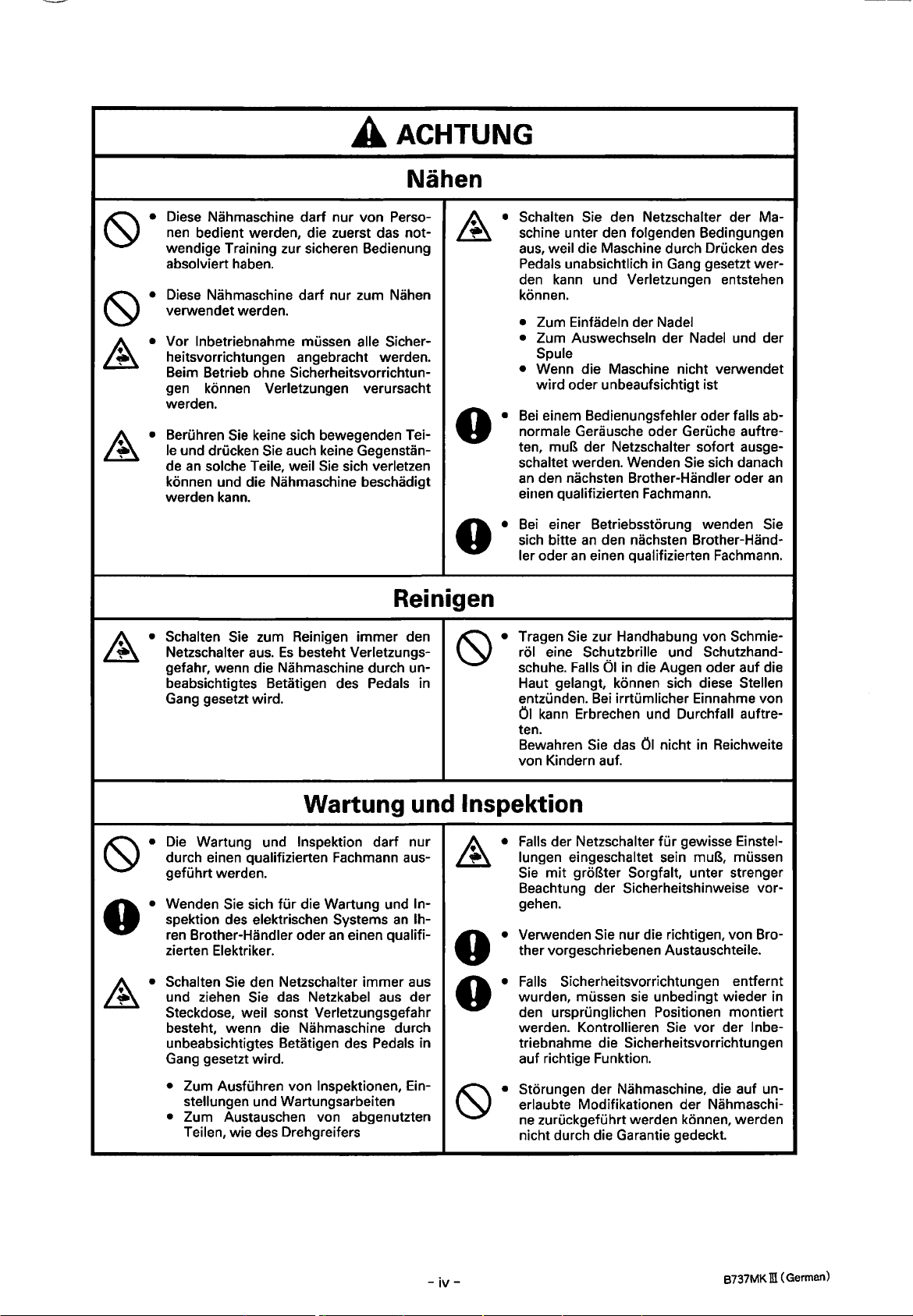
AACHTUNG
Nahen
Diese Nahmaschine dart nur von Perso-
nen bedient werden, die zuerst das notwendige Training zur sicheren Bedienung
absolviert haben.
Diese Nahmaschine darf nur zum
verwendet werden.
Vor lnbetriebnahme mussen aile Sicherheitsvorrichtungen angebracht werden.
Beim Betrieb ohne Sicherheitsvorrichtungen konnen Verletzungen verursacht
werden.
Beruhren
le
de
konnen und die Nahmaschine beschadigt
werden kann.
~·
Schalten
Netzschalter
gefahr, wenn die Nahmaschine durch unbeabsichtigtes Betatigen des Pedals in
Gang
Nahen
Sie
und drucken Sie auch keine Gegenstan-
an
solche Teile, weil
keine sich bewegenden Tei-
Sie
sich verletzen
Reinig en
Sie
zum Reinigen immer den
aus.
Es
besteht Verletzungs-
gesetzt wird.
.4..
Schalten Sie den Netzschalter der Maschine unter den folgenden Bedingungen
aus,
weil die Maschine durch Drucken des
Pedals unabsichtlich
den
kann
und Verletzungen entstehen
konnen.
• Zum Einfadeln der Nadel
• Zum Auswechseln der Nadel und der
Spule
•
Wenn die Maschine nicht verwendet
wird oder unbeaufsichtigt ist
Bei
einem Bedienungsfehler oder falls ab-
normale Gerausche oder Geruche auftre-
muB der Netzschalter sofort ausge-
ten,
schaltet werden. Wenden
an
den nachsten Brother-Handler oder
einen qualifizierten Fachmann.
Bei
einer Betriebsstorung wenden Sie
sich bitte
ler oder
Tragen
rol
schuhe. Falls
Haut gelangt, konnen sich diese
entzunden.
01
ten.
Bewahren
von Kindern auf.
an
den nachsten Brother-Hand-
an
einen qualifizierten Fachmann.
Sie
zur Handhabung von Schmie-
eine Schutzbrille und Schutzhand-
01
kann
Bei
Erbrechen und Durchfall auftre-
Sie
in
Gang gesetzt wer-
Sie sich danach
an
in
die Augen oder auf die
irrtumlicher Einnahme von
das
01
nicht
Stellen
in
Reichweite
Wartung und lnspektion
Die
Wartung und lnspektion dart nur
durch einen qualifizierten Fachmann ausgefuhrt werden.
Wenden
spektion des elektrischen Systems
ren Brother-Handler oder
zierten Elektriker.
Schalten
und ziehen Sie das Netzkabel aus der
Steckdose, weil sonst Verletzungsgefahr
besteht, wenn die Nahmaschine durch
unbeabsichtigtes Betatigen des Pedals in
Gang gesetzt wird.
• Zum AusfUhren von lnspektionen, Ein-
• Zum Austauschen von abgenutzten
Sie
sich fUr die Wartung und ln-
an
einen qualifi-
Sie
den Netzschalter immer
stellungen und Wartungsarbeiten
Teilen, wie des Drehgreifers
an
lh-
aus
Falls
der Netzschalter fUr gewisse Einstellungen eingeschaltet sein muB, mussen
Sie
mit
Beachtung der Sicherheitshinweise vorgehen.
groBter Sorgfalt, unter stranger
A • Verwenden Sie nur die richtigen, von Bro-
W ther vorgeschriebenen Austauschteile.
Falls
Sicherheitsvorrichtungen entfernt
o·
wurden, mussen sie unbedingt wieder in
den ursprunglichen Positionen montiert
werden. Kontrollieren
triebnahme die Sicherheitsvorrichtungen
auf richtige Funktion.
Storungen der Nahmaschine, die auf unerlaubte Modifikationen der Nahmaschine
zuruckgefuhrt werden konnen, werden
nicht durch die Garantie gedeckt.
Sie
vor der lnbe-
-
iv-
B737MK m (German)
Page 6
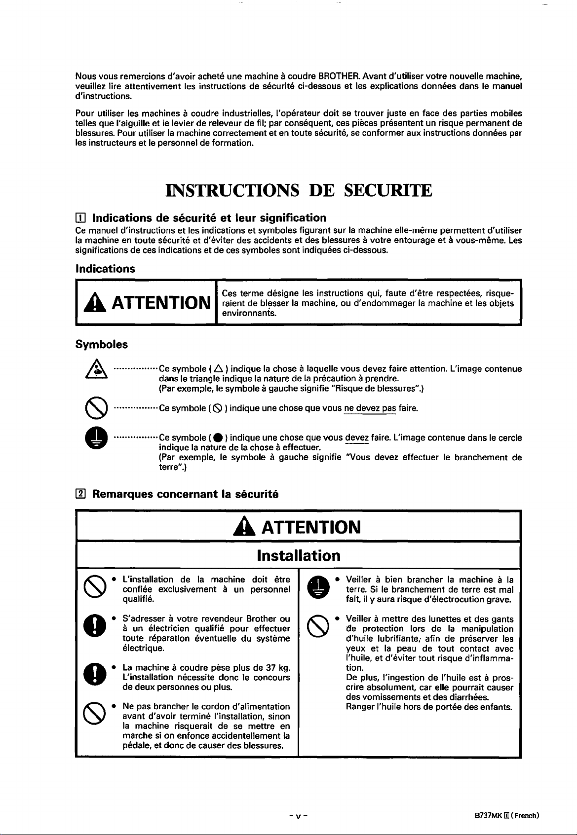
Nous vous remercions d'avoir achete une machine a coudre
veuillez lire attentivement les instructions de securite ci-dessous et les explications donnees dans
d'instructions.
BROTHER.
Avant d'utiliser votre nouvelle machine,
le
manuel
Pour utiliser les machines a coudre industrielles, l'operateur doit
telles que l'aiguille et
blessures. Pour utiliser
les instructeurs
[I] Indications de securite
Ce
manuel d'instructions
Ia
machine
significations de
en
le
levier de releveur de fil; par consequent,
Ia
machine correctement
et
le
personnel de formation.
et
en
INSTRUCTIONS
et
leur signification
et
toute securite et d'eviter des accidents
ces
indications et de
les indications
et
symboles figurant sur
ces
symboles sont indiquees ci-dessous.
toute securite,
DE
et
des blessures a votre entourage
Indications
Ces
terme designe les instructions qui, faute d'etre respectees, risque-
A ATTENTION
raient de
environnants.
bl~sser
Ia
machine, ou
Symboles
················Ce symbole ( l::i) indique
dans le triangle indique
(Par
exem;>le, le symbole a gauche signifie "Risque de blessures".)
Ia
chose a laquelle vous devez faire attention. L'image contenue
Ia
nature de
Ia
precaution a prendre.
se
trouver juste
ces
pieces presentent un risque permanent de
se
conformer aux instructions donnees par
en
face des parties mobiles
SECURITE
Ia
machine elle-meme permettent d'utiliser
d'
endommager
eta
vous-meme.
Ia
machine et les objets
Les
················Ce
·•••···••••····•
00
Remarques concernant Ia securite
symbole {
Ce
symbole { e ) indique une chose que vous devez fa ire. L'image contenue dans
indique
(Par
exemple, le symbole a gauche signifie "Vous devez effectuer le branchement
terre".)
{S))
Ia
nature de
indique une chose que vous
A ATTENTION
L'installation de
confiee exclusivement a un personnel
qualifie.
S'
adresser a votre revendeur Brother ou
a un electrician qualifie pour effectuer
toute reparation eventuelle du systeme
electrique.
La
machine a coudre pese plus
L'installation necessite done le concours
de deux personnes ou plus.
Ne
pas brancher
avant d'avoir termine !'installation, sinon
Ia
machine risquerait de
marche
pedale, et done de causer des blessures.
si
on enfonce accidentellement
Ia
machine doit etre
le
cordon d'alimentation
se
Ia
chose a effectuer.
Installation
de
37
kg.
mettre
en
Ia
ne
devez pas faire.
le
--
Veiller a bien brancher
terre.
Si
le
fait, il y aura risque d'electrocution grave.
Veiller
'de
d'huile
yeux et
l'huile, et d'eviter
tion.
De
plus, !'ingestion de l'huile est a proscrire absolument, car elle pourrait causer
des vomissements
Ranger l'huile hors de portae des enfants.
branchement de terre est mal
a mettre des lunettes et des gants
protection lors de
lubrifiante,· afin de preserver les
Ia
peau de
Ia
machine a
Ia
manipulation
tout
tout
et
contact avec
risque d'inflamma-
des diarrheas.
cercle
de
Ia
-v-
B737MK m (French)
Page 7
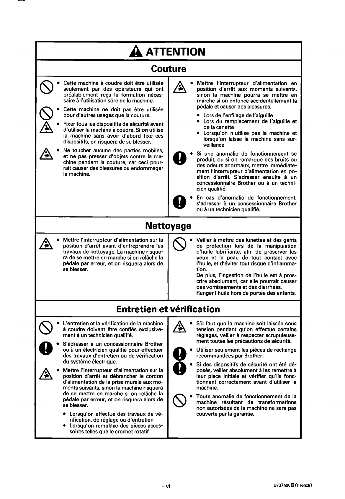
A ATTENTION
Couture
&·
&·
Cette machine a coudre doit etre utilisee
par
des
seulement
prealablement
saire
a !'utilisation
Cette machine
pour d'autres usages que
Fixer tous
d'utiliser
Ia
machine
dispositifs,
Ne
et
ne
chine pendant
rait causer
Ia
machine.
les
dispositifs
Ia
machine a coudre.
sans
on
toucher aucune des parties mobiles,
pas
presser d' objets contre
des
operateurs qui ont
re~u
Ia
formation neces-
sOre
de
Ia
machine.
ne
doit
pas
etre utilisee
Ia
couture.
de
securite avant
avoir d'abord fixe
risquera
Ia
couture, car ceci pour-
blessures
Si
de
se
blesser.
ou
endommager
on utilise
ces
Ia
ma-
Nettoyage
Mettre l'interrupteur d'alimentation sur
position d'arret avant d'entreprendre les
travaux
ra
pedale par erreur, et on risquera alors
se
de
de
se
blesser.
nettoyage.
mettre
en
La
machine risque-
marche
si
on relache
Ia
Ia
de
&·
Mettre l'interrupteur d'alimentation
position
sinon
marche
pedale et causer des blessures.
•
•
• Lorsqu'oh n'utilise
Si
produit,
des odeurs anormaux, mettre immediate-
ment
sition
concessionnaire Brother ou
cian qualifie.
En
s'adresser
ou
Veiller
de protection
d'huile lubrifiante,
yeux et
l'huile, et d'eviter tout risque d'inflammation.
De
crire
des vomissements et
Ranger l'huile hors
d'
arret aux moments suivants,
Ia
machine pourra
si
on
enfonce accidentellement
Lors
de
l'enfilage
Lors
du
de
lorsqu'
veillance
une anomalie
cas
remplacement de l'aiguille et
Ia
canette
on
ou
si
l'interrupteur d'alimentation
d'arret
d'anomalie de fonctionnement,
de
laisse
Ia
de
on
remarque des bruits ou
S'adresser ensuite a un
se
mettre
l'aiguille
pas
Ia
machine et
machine
fonctionnement
a
un
a un concessionnaire Brother
a un technician qualifie.
a mettre des lunettes et
lors de
afin
Ia
peau
de
tout contact avec
plus, !'ingestion
absolument, car elle pourrait causer
de
l'huile est a pros-
des
de
portee des enfants.
des
Ia
manipulation
de
preserver les
diarrheas.
sans
en
techni-
en
en
sur-
se
po-
gants
Ia
L' entretien et
a coudre doivent etre confies exclusive-
ment a un technician qualifie.
S'adresser a
ou
des
du systeme
~·
Mettre l'interrupteur d'alimentation sur
position d'arret et debrancher
d'alimentation
ments suivants, sinon
de
pedale par erreur, et on risquera alors de
se
• Lorsqu'on effectue
• Lorsqu'on remplace
Entretien
Ia
verification de
un
concessionnaire Brother
Ia
machine
a un electrician qualifie pour effectuer
travaux d' entretien
se
blesser.
rification,
soires
mettre
telles que
electrique.
de
en
de
reglage
ou
de
verification
Ia
prise murale aux mo-
Ia
marche
des
ou
des
le
crochet rotatif
le
machine risquera
si
on relache
travaux
d'entretien
pieces acces-
cordon
de
ve-
et
verification
Ia
Ia
S'il taut que
tension pendant qu'on effectue certains
reglages, veiller a respecter scrupuleuse-
ment toutes les precautions de securite.
Utiliser seulement
recommandees par Brother.
Si
des dispositifs
poses, veiller absolument a les remettre a
leur place initiale et verifier qu'ils fonctionnent correctement avant
machine.
Toute
machine resultant de transformations
non autorisees de
couverte par
Ia
anomalie
Ia
machine soit laissee sous
les
pieces
de
rechange
de
securite ont ete de-
d'utiliser
de
fonctionnement de
Ia
machine
garantie.
ne
sera
pas
Ia
Ia
-vi-
B737MK m (French)
Page 8
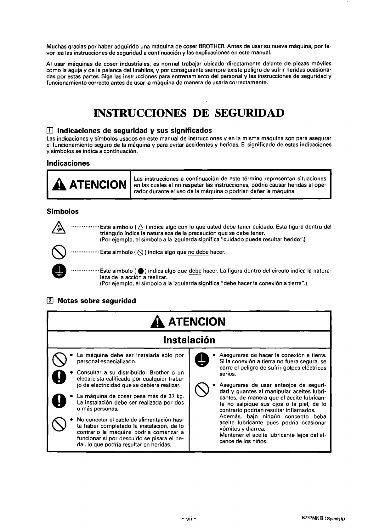
Muchas gracias
vor
lea
las
instrucciones de seguridad a continuaci6n y las explicaciones
por
haber adquirido una maquina de coser
BROTHER.
Antes de usar
en
este manual.
su
nueva maquina,
por
fa-
usar maquinas de coser industriales,
AI
como
Ia
aguja y de
das por estas partes. Siga
funcionamiento correcto antes de usar
Ia
palanca del tirahilos, y por consiguiente siempre existe peligro de sufrir heridas ocasiona-
las instrucciones para entrenamiento del personal y las instrucciones de seguridad y
INSTRUCCIONES DE SEGURIDAD
IJJ
lndicaciones
Las
indicaciones y simbolos usados
el
funcionamiento seguro de
y simbolos
se
indica a continuaci6n.
lndicaciones
AATENCION
Simbolos
·••··••••·· ··•••
de
seguridad y sus significados
en
Ia
maquina y para evitar accidentes y heridas.
Las
en
radar durante
Este
simbolo
triangulo
(Por
ejemplo,
(D.
indica
el
Ia
simbolo a
es
normal trabajar ubicado directamente delante de piezas m6viles
Ia
maquina de manera de usarla correctamente.
este manual de instrucciones y
instrucciones a continuaci6n de este termino representan situaciones
las cuales
) indica algo con lo que usted debe tener cui dado.
naturaleza de
el
no respetar las instrucciones, podria causar heridas
el
uso de
Ia
maquina o podrian danar
Ia
Ia
precauci6n que
izquierda significa "cuidado puede resultar herido".)
en
Ia
misma maquina son para asegurar
El
significado de estas indicaciones
Ia
maquina.
Esta
se
debe tener.
figura dentro del
al
ope-
III
................ Este
................
Notas
La
personal especializado.
Consultar a
electricista calificado por cualquier trabajo
La
La
0 mas personas.
No conectar
ta haber
contrario
funcionar
dal, lo que podria resultar
sabre
simbolo
Este
simbolo (
leza
de
(Por ejemplo,
seguridad
(~)indica
e)
indica algo que debe hacer.
Ia
acci6n a realizar.
el
simbolo a
algo que no debe hacer .
Ia
AATENCION
lnstalaci6n
maquina debe ser instalada solo por
su
distribuidor Brother o
de electricidad que
maquina de coser pesa mas de
instalaci6n debe ser realizada por dos
el
completado
Ia
maquina podria comenzar a
si
por descuido
se
debiera realizar.
37
cable de alimentaci6n has-
Ia
instalaci6n, de lo
se
pisara
en
el
heridas.
La
figura dentro del circulo indica
--
izquierda significa "debe hacer
Asegurarse de hacer
Si
Ia
conexi6n a tierra no fuera segura,
corre
el
un
kg.
pe-
serios.
Asegurarse de usar anteojos de seguri-
dad
cantes, de manera que
te no salpique
contrario podrian resultar inflamados.
Ademas, bajo ningun concepto beba
aceite
v6mitos
Mantener
cance de los ninos.
peligro de sufrir golpes electricos
y guantes
lubricante pues podria ocasionar
y diarrea.
el
Ia
natura-
Ia
conexi6n a tierra".)
Ia
conexi6n a tierra.
al
manipular aceites lubri-
el
aceite lubrican-
sus
ojos o
aceite lubricante lejos del al-
Ia
piel, de lo
se
-vii-
B737MKID (Spanish)
Page 9
A ATENCION
Costura
Solo operarios que hayan sido entrena-
~·
~·
A.
~·
dos especialmente deben usar esta
maquina de coser.
La
para otro uso que no
lnstalar todos los dispositivos de seguri-
dad antes de usar
Ia
sitivos de seguridad podria resultar herido.
No tocar ninguna de
presionar ningun objeto contra
na
das o Ia
Desconectar
de comenzar cualquier trabajo de limpieza.
nar
que podria resultar
maquina de coser no debe ser usada
maquina
al
de
coser, pues podria resultar
maquina podria resultar daiiada.
sea
coser.
Ia
maquina de coser.
coser
se
usa
las
piezas moviles o
sin los dispo-
Ia
maqui-
en
heri-
Limpieza
el
interrupter principal antes
La
maquina podria comenzar a funcio-
si
por descuido
se
en
heridas.
pisara
el
pedal, lo
Si
A·
el
Desconectar
siguientes casas, de lo contrario
maquina podria comenzar a funcionar
por descuido
podria resultar
•
AI
enhebrar
•
AI
cambiar
•
AI
no usar
dejandola sin cuidado
Si
comete un error
si
se
escuchan ruidos extraiios o
ten olores
diatamente
consultar
cano o a un tecnico calificado.
Si
Ia
maquina no funcionara correctamente, consultar
cercano o a un tecnico calificado.
Asegurarse de usar anteojos
dad y guantes
cantes, de manera que
te no salpique
trario podrian resultar inflamados.
Ademas, bajo ningun concepto
beber aceite lubricante pues podria ocasionar vomitos y diarrea.
Mantener
cance de los
interrupter principal
se
pisara
el
en
heridas.
Ia
aguja
Ia
aguja o
Ia
maquina y alejarse de ella
al
extraiios, desconectar inmeel
interruptor principal. Luego
al
distribuidor Brother mas cer-
al
distribuidor Brother mas
al
manipular aceites lubri-
en
ojos o
el
aceite lubricante lejos del alniiios.
pedal, lo que
Ia
bobina
usar
Ia
el
aceite lubrican-
Ia
piel,
en
los
maquina, o
se
sian-
de
seguri-
de
lo con-
se
debe
Ia
si
Mantenimiento e inspeccion
El
mantenimiento y
maquina debe ser realizado solo por
tecnico calificado.
Consultar a
electricista calificado por cualquier trabajo de mantenimiento e inspecci6n electrica
que
Desconectar
senchufar
macorriente
cases,
comenzar a funcionar
pisara
heridas.
•
AI
mantenimiento.
•
AI
su
se
debiera realizar.
el
el
cable de alimentacion del toen
de lo contrario
el
pedal, lo que podria resultar
inspeccionar, ajustar o realizar
cambiar piezas como
Ia·
inspeccion de
distribuidor Brother o un
interrupter principal y de-
Ia
pared
en
los siguientes
Ia
maquina podria
si
por descuido
Ia
lanzadera.
un
se
en
Ia
el
&·
~·
Si
conectado
tener mucho cuidado de tener
las
Usar
cadas por Brother.
Si
dispositivos de seguridad, asegurarse de
volver a instalarlos a
y verificar que funcionan correctamente
antes
Los
caciones no autorizadas
seran cubiertos por
el
interrupter principal debiera estar
al
realizar un ajuste,
siguientes precauciones.
solo
las
piezas de repuesto especifi-
se
hubieran desmontado alguno de los
su
posicion original
de
usar
Ia
maquina.
problemas que resultaran de modifi-
en
Ia
garantia.
se
en
cuenta
Ia
maquina no
debe
-viii-
B737MK ill (Spanish)
Page 10
[!]
[!]
Warning labels
[!]
Warnschilder
Etiquettes d' avertissement
[!]
Etiquetas de advertencia
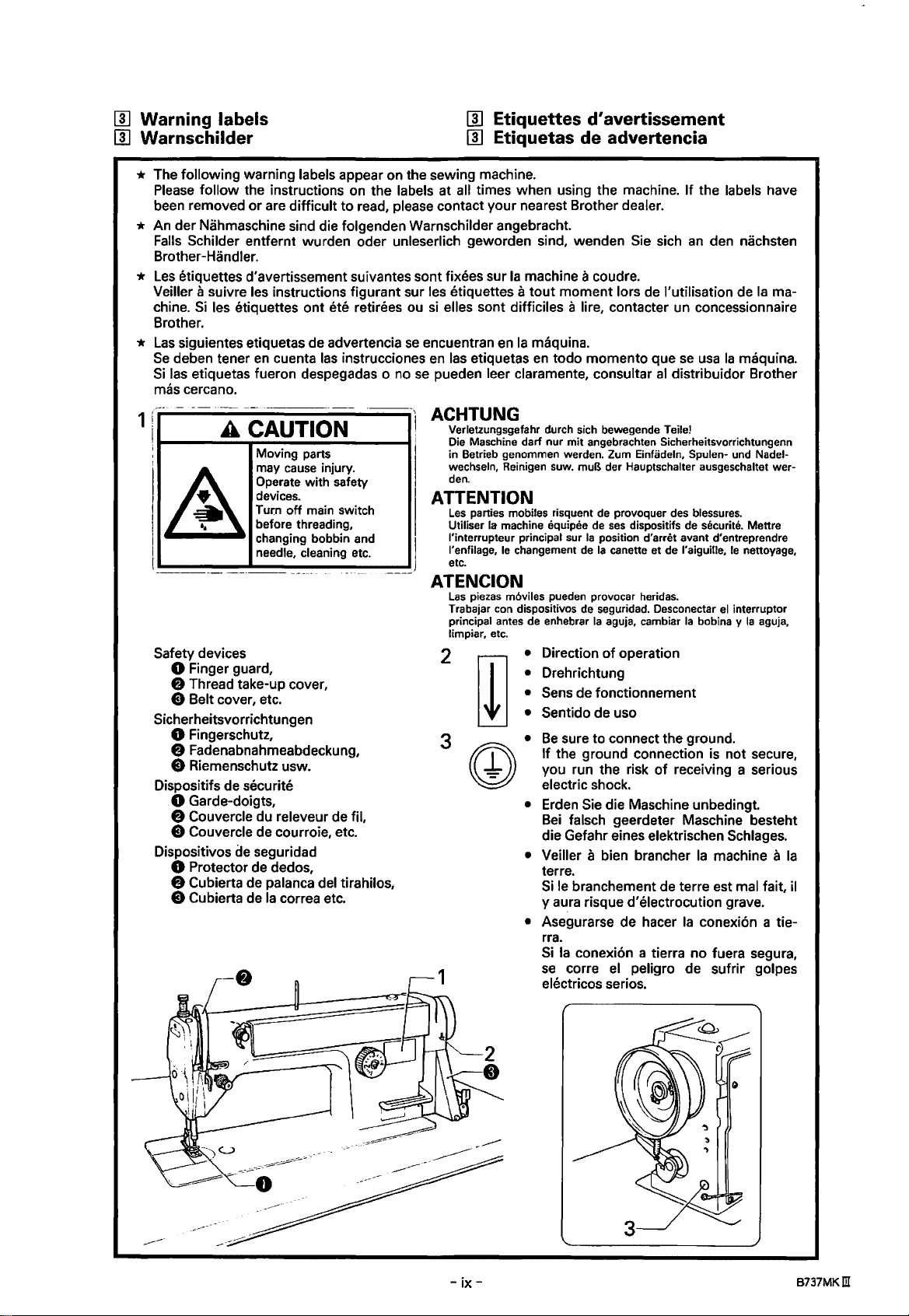
* The following warning labels appear on the sewing machine.
Please
follow the instructions on the labels at all times when using the machine. If the labels have
been removed
or
are difficult to read, please contact your nearest Brother dealer.
* An der Nahmaschine sind die folgenden Warnschilder angebracht.
Falls
Schilder entfernt wurden oder unleserlich geworden sind, wenden
Brother-Handler.
*
Les
etiquettes d'avertissement suivantes sont fixees sur
Veiller a suivre les instructions figurant sur les etiquettes a
chine.
Si
Brother.
*
Las
Se
Si
mas
•
c-
1
I
:
A
les etiquettes ont ete retirees ou
siguientes etiquetas de advertencia
deben tener
las
etiquetas fueron despegadas o no
cercano .
en
cuenta
A CAUTION
Moving parts
may cause injury.
Operate with safety
devices.
Turn
off
before threading,
changing bobbin and
needle, cleaning etc.
main switch
l
Safety devices
0 Finger guard,
las
instrucciones
--
si
elles sont difficiles. a lire, contacter un concessionnaire
se
encuentran
en
las
se
pueden leer claramente, consultar
\
ACHTUNG
I
Verletzungsgefahr durch sich bewegende Teile!
Die Maschine darf nur
in Betrieb genommen werden. Zum Einfadeln, Spulen· und Nadelwechseln, Reinigen suw. muB der Hauptschalter ausgeschaltet werden.
I
ATTENTION
Les
Utiliser
l'interrupteur
l'enfilage,
etc.
I
A
TEN
Las
Trabajar con dispositivos de seguridad. Desconectar
principal antes de enhebrar
limpiar, etc.
2
8 Thread take-up cover,
Q Belt cover, etc.
Sicherheitsvorrichtungen
0 Fingerschutz,
8 Fadenabnahmeabdeckung,
3
Q Riemenschutz usw.
Dispositifs de securite
0 Garde-doigts,
8 Couvercle du releveur de fil,
Q Couvercle de courroie, etc.
D~pos~vosdeseguridad
0 Protector de dedos,
8 Cubierta de palanca del tirahilos,
e Cubierta de
Ia
Correa
etc.
Ia
en
etiquetas
parties mobiles risquent de provoquer des blessures.
Ia
machine equipee de
le
changement de
CION
piezas m6viles pueden provocar heridas.
Sie
sich
an
den nachsten
machine a coudre.
tout
moment lors
Ia
maquina.
en
todo momenta que
mit
angebrachten Sicherheitsvorrichtungenn
principal sur
• Direction
• Drehrichtung
• Sens de fonctionnement
• Sentido de uso
•
• Erden Sie die Maschine unbedingt.
• Veiller
• Asegurarse de hacer
Ia
Ia
Be
sure to connect the ground.
If
the ground connection is not secure,
you run the risk
electric shock.
Bei
falsch geerdeter Maschine besteht
die Gefahr eines elektrischen Schlages.
a bien brancher
terre.
Si
le
branchement de terre est mal fait, il
y aura risque d'electrocution grave.
rra.
Si
Ia
conexi6n a tierra no fuera segura,
se
corre
electricos serios.
de
!'utilisation de
se
usa
al
distribuidor Brother
ses
dispositifs de securite. Mettre
position d'arret avant d'entreprendre
Ia
canette et de l'aiguille,
aguja, cambiar
of
operation
of
receiving a serious
el
peligro de sufrir golpes
Ia
le
el
Ia
Ia
interruptor
bobina y
Ia
machine a
conexi6n a tie-
Ia
ma-
maquina.
nettoyage,
Ia
aguja,
Ia
-
ix-
B737MKm
Page 11
CONTENTS
INHALT
NAMFS
MACHINE
WORK TABLE AND MOTOR
[I]
[II
INSTALLATION
[I]
[II
00
1!1
[!]
[!]
[lJ Installing the belt cover .................................................
[I]
1!1
1!]1
PREPARATION BEFORE SEWING
[I]
[II
00
1!1
[!]
[!]
[lJ Thread wiper (-400, -900) ............................................
[I]
SEWING
THREAD TENSION
[I]
[II
STANDARD ADJUSTMENTS
[I]
[II
00
1!1
[!]
[!]
[lJ Fixed knife and movable knife replacement ............ 38
[I]
CLEANING
OF
MAJOR
SPECIFICACIONS
PARTS
.................................
.................................
..
...............................
Work Table ........................................................................ 3
Motor
.................................................................................. 4
...............................................................
Installing the machine head ......................................... 5
Installing the knee lifter assembly .............................. 7
Adjusting the knee lifter ................................................ 7
Installing the belt ............................................................. 9
Ground
Installing the bobbin winder .........................................
Installing the·cotton stand ............................................ 14
Lubrication .........................................................................
Checking the machine pulley rotating direction
Removing the bobbin
Winding the lower thread .............................................
Threading the lower thread ..........................................
Installing the needle ........................................................
Threading the upper thread .........................................
Adjusting the stitch length ............................................
Automatic presser lifter (-900) ....................................
Adjusting the thread tension ........................................
Adjusting the presser foot pressure ..........................
Adjusting the presser
Adjusting the feed dog height and angle ................
Adjusting the needle bar height .................................
Adjusting the needle and rotary hook timing .........
Adjusting the thread tension spring .......................... 34
Synchronizer adjustment ...............................................
Adjusting the upper shaft and rotary hook
lubrication amount .......................................................... 39
wire
connections .............................................. 9
.....
....................
case
...........................................
................................................................................
.......................................................
..................................
foot
height ...............................
..........................................................................
10
11
15
16
17
17
18
19
20
21
22
22
23
24
26
26
27
28
29
30
32
33
36
40
HAUPTTEILE
TECHNISCHE DATEN................................................. 2
2
NAHTISCH UND MOTOR
3
rn
Nahtisch .............................................................................. 3
[!]
Motor
MONTAGE
5
[I]
Montage des Maschinenoberteils ................................ 5
[!]
Montage der Kniehebel .................................................. 7
00
Einstellen des Kniehebels .............................................. 7
1!1
Riemenmontage ............................................................... 9
[!]
AnschluB des Erdungskabels ........................................ 9
[!]
Montage des Spulers .....................................................
[lJ Montage des Riemenschutzes .....................................
[I]
Montage des Spulentragers ..........................................
1!1
Schmierung .......................................................................
1!]1
Kontrolle der Nahmaschinen-
Riemenscheibendrehrichtung ........................................ 16
...................................................................
.......................................
.................................................................................. 4
..........................................................................
VORBEREITUNGEN ZUM NAHEN
[I]
Herausnehmen der Spulenkapsel ................................
[II
Aufwickeln des Unterfadens .........................................
00
Einfadeln des Unterfadens ............................................ 19
1!1
Einsetzen der Nadel ........................................................
00
Einfadeln des Oberfadens .............................................
[!]
Einstellen der Stichlange ...............................................
[lJ Fadenwischer (-400, -900) ............................................
[I]
Automatische Anhebevorrichtung (-900) ..................
NAHEN
FADENSPANNUNG
[I]
[II
STANDARDEINSTELLUNGEN
[I]
[II
00
1!1
[I)
[!]
[lJ Ersetzen des festen und beweglichen Messers
III
..................................................................................
.......................................................
Einstellen der Fadenspannung .....................................
Einstellen des StoffdruckerfuBdrucks .........................
...............................
Einstellen der StoffdruckerfuBhohe ............................
Einstellen der Hohe und der Neigung des
Transporteurs ....................................................................
Einstellen der Nadelstangenhohe ................................
Einstellen der Nadei-Greifersynchronisierung ..........
Einstellen der Fadenspannungsfeder .......................... 34
Einstellen der Synchronisators .....................................
Einstellen der Schmierung der oberen Welle und
des Drehgreifers ...............................................................
...................
......
.
3
5
10
11
14
15
17
17
18
20
21
22
22
23
24
26
26
27
28
29
30
32
33
36
38
39
TROUBLESHOOTING
..................................................
44
REINIGUNG
FEHLERSUCHE
.......................................................................
................................................................
40
47
Page 12
TABLE
DES
MATIERES CONTENIDO
NOM DES PIECES PRINCIPALES
SPECIFICATIONS
TABLE DE TRAVAIL
[I
Table de travail ................................................................ 3
00
Moteur ................................................................................ 4
INSTALLATION
[JJ
Installation de
00
Installation de !'ensemble de releveur
00
Reglage du releveur
[!]
Installation de
III Raccord
00
Installation du bobineur de canette ...........................
[1]
Installation du couvercle de courroie .........................
00
Installation de
.du
DE
LA MACHINE
Ef
MOTEUR
...............................................................
Ia
tete de machine .............................. 6
au
genou .................................... 8
Ia
courroie .............................................. 9
cable de mise a
Ia
broche porte-bobine ....................... 14
Ia
......................
...............
.................
au
genou
...
terre ......................... 9
III Lubrification ............................................................•..........
[2]
Verification du sens de rotation de
machine .............................................................................. 16
PREPARATIFS AVANT LA COUTURE
[JJ
Retrait de
00
Bobinage du fil inferieur ................................................ 18
00
Enfilage du fil inferieur .................................................. 19
[!]
Installation de l'aiguille ...................................................
Ia
boite a canette ........................................
Ia
poulie de
.........
III Enfilage du fil superieur ................................................
00
Reglage
[1]
Tire-fil (-400, -900) .........................................................
[!]
Dispositif de relevage automatique de pied
presseur
COUTURE
TENSION DU FIL
[JJ
Reglage de
00
Reglage de
REGLAGES STANDARD
IIJ
Reglage de
[!]
Reglage de l'angle
d'
[I) Reglage de
1!1
Reglage de
crochet rotatif ...................................................................
1!1
Reglage du ressort de tension du til .........................
00
Reglage du synchroniseur .............................................
[1]
Remplacement du couteau fixe et du couteau
mobile
[!]
Reglage de
superieur et du crochet rotatif ....................................
de
Ia
longueur de point ................................
(-900) .................................................................
............................................................................
..........................................................
Ia
tension du fil ...................................
Ia
pression du pied presseur .................
~.....
...........................................
Ia
hauteur du pied presseur ..................
et
de
Ia
entrainement ..................................................................
Ia
hauteur de
Ia
synchronisation de l'aiguille
.................................................................................
Ia
quantite de lubrification de l'arbre
hauteur de
Ia
barre a aiguille ...........
Ia
griffe
et
du
10
11
15
17
17
20
21
22
22
23
24
26
26
27
28
29
30
32
33
35
37
38
39
NOMBRES DE LAS PIEZAS
PRINCIP ALES
2
..................................................................
ESPECIFICACIONES DE LA MAQUINA
3
MESA DE TRABAJO Y MOTOR
[JJ
Mesa de trabajo ............................................................... 3
00
Motor
.................................................................................. 4
........................
6
INSTALACION
[I
8
lnstalacion de
00
lnstalacion del conjunto del levantador de
rodilla .................................................................................. 8
[[) Ajuste del levantador de rodilla .................................. 8
[!]
lnstalacion de
..................................................................
Ia
cabeza de
Ia
correa .................................................. 9
Ia
maquina .................... 6
III Conexion del cable a tierra .......................................... 9
00
lnstalacion de
[1]
lnstalacion de
00
lnstalacion del soporte del carrete ............................. 14
Ia
bobinadora ........................................
Ia
cubierta de
Ia
correa ......................
III Lubricacion ........................................................................
[2]
Verificacion de
polea de
Ia
Ia
direccion de rotacion de
maquina ....................................................... 16
PREPARATIVOS ANTES DE COSER
[JJ
Manera de sacar
00
Bobinado del hilo inferior ............................................. 18
[[) Enhebrado del hilo inferior ........................................... 19
[!]
Colocacion de
Ia
caja de
Ia
aguja ...................................................
Ia
bobina .......................
III Enhebrado del hilo superior .........................................
00
Ajuste del largo de puntada .........................................
[1]
Limpia-hilos (-400, -900) ...............................................
[!]
Alzador automatico del prensatelas (-900) ..............
COSTURA
TENSION DEL HILO
[JJ
Ajuste de
!l1
Ajuste de
AJUSTES ESTANDARES
[JJ
Ajuste de
!l1
Ajuste de
[[) Ajuste de
[!]
Ajuste de sincronizacion de
lanzadera ............................................................................
............................................................................
...................................................
Ia
tension del hilo ........................................
Ia
presion del prensatelas .........................
............................................
Ia
altura del prensatelas .............................
Ia
altura y el angulo del alimentador
Ia
altura de
Ia
barra de aguja .................. 32
Ia
aguja y
III Ajuste del resorte del tirahilos ....................................
00
Ajuste del sincronizador ..................................... -.........
[1]
Cambio de
movil ................................................................................... 38
[!]
Ajuste de
lanzadera ............................................................................ 39
Ia
cuchilla estacionaria-cuchilla
Ia
lubricacion del eje superior y
...............
Ia
Ia
Ia
.......
.....
.
2
3
6
10
11
15
17
17
20
21
22
22
23
24
26
26
27
28
29
30
33
35
37
NEI'I'OYAGE
RESOLUTION DES PROBLEMES
.....................................................................
........................
40
50
LIMPIEZA
LOCALIZACION DE A VERIAS
............................................................................
...........................
40
53
Page 13
NAMES OF MAJOR PARTS
NOM
DES
PIECES
PRINCIP
ALES
HAUPTTEILE
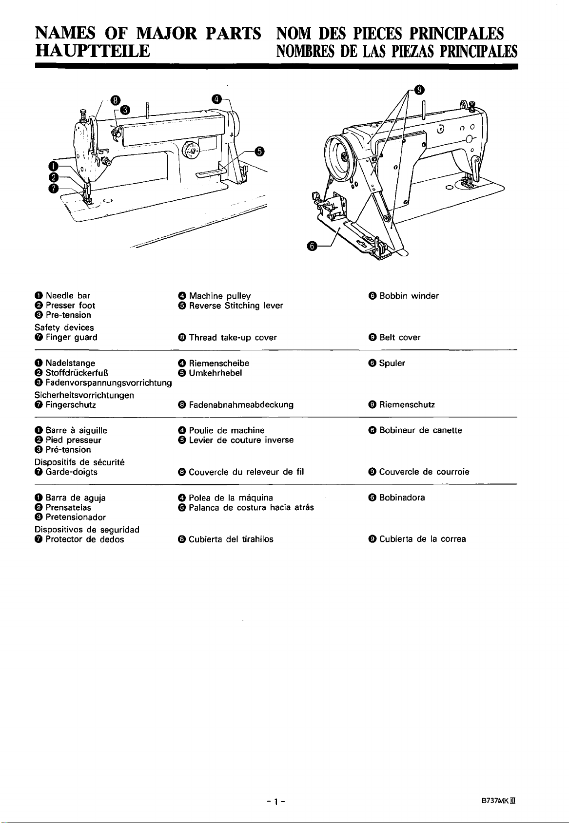
0 Needle bar
8 Presser
E) Pre-tension
Safety devices
0 Finger guard
foot
NOMBRES
8 Machine pulley
0 Reverse Stitching lever
0 Thread take-up cover
DE
LAS
PIEZAS
0 Bobbin
0 Belt cover
PRINCIP
winder
ALES
0 Nadelstange
8 StoffdruckerfuB
E)
Fadenvorspannungsvorrichtung
Sicherheitsvorrichtungen
0 Fingerschutz
0 Barre a aiguille
8 Pied presseur
E) Pre-tension
Dispositifs de
0 Garde-doigts
0 Barra de aguja
8 Prensatelas
Pretensionador
E)
Dispositivos de seguridad
0 Protector de dedos
securite
8 Riemenscheibe
0 Umkehrhebel
0 Fadenabnahmeabdeckung
8 Poulie de machine
0 Levier de couture inverse
0 Couvercle du releveur de til
8 Polea de
0 Palanca de costura hacia atras
0 Cubierta del tirahilos
Ia
maquina
0 Spuler
0 Riemenschutz
0 Bobineur de canette
0 Couvercle de courroie
0 Bobinadora
0
Cu
bierta de
Ia
cor
rea
- 1 -
B737MKill
Page 14
MACHINE
SPECIFICACIONS
SPECIFICATIONS
DE
LA
MACHINE
TECHNISCHE .DATEN
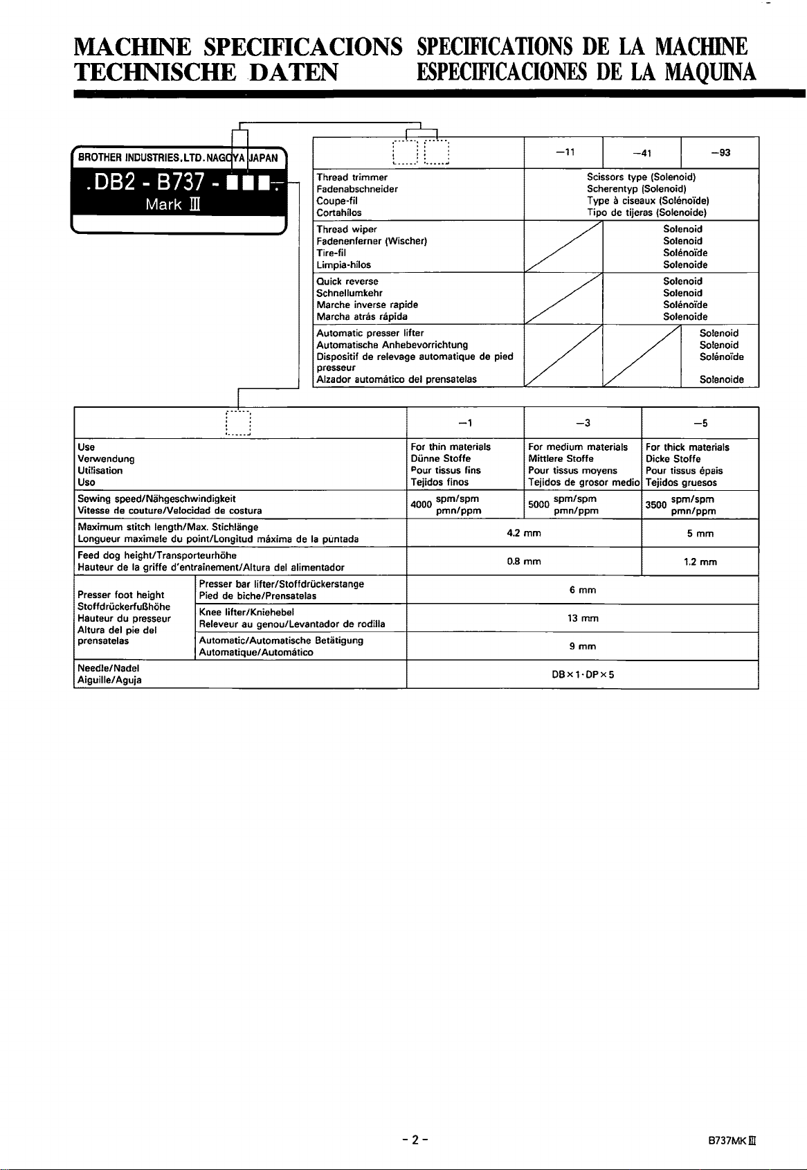
Thread trimmer
Fadenabschneider
Coupe-til
Cortahilos
Thread wiper
Fadenenferner (Wischer)
Tire-fil
Limpia-hilos
Quick reverse
Schnellumkehr
Marche inverse rapide
Marcha atras rapida
Automatic presser lifter
Automatische Anhebevorrichtung
Dispositif
presseur
Alzador automatico del prensatelas
Use
Verwendung
Utilisation
Uso
Sewing speed/Nahgeschwindigkeit
Vitesse de couture/Velocidad
Maximum stitch length/Max. Stichlange
Longueur maximale du point/Longitud
Feed
dog height/Transporteurhohe
Ia
Hauteur de
Presser foot height
Stoffd rOckerfuBhohe
Hauteur du presseur
Altura del pie del
prensatelas
Needle/ Nadel
Aiguille/ Aguja
griffe d'entrainement/Aitura
de
costura
maxima
de
Ia
puntada
del
alimentador
Presser bar lifter/Stoffdri.ickerstange
Pied
de biche/Prensatelas
Knee
lifter/Kniehebel
au
Releveur
Automatic/ Automatische Betatigung
Automatique/ Automatico
genou/Levantador de rodilla
ESPECIFICACIONES
de
relevage automatique de pied
-1
For thin materials
Dunne Stoffe
Pour tissus fins
Tejidos finos
4000
spm/spm
pmn/ppm
-11
Scissors type (Solenoid)
Scherentyp (Solenoid)
Type a ciseaux
Tipo
-3
For medium materials
Mittlere Stoffe
Pour tissus moyens
Tejidos de grosor medio
5000
spm/spm
pmn/ppm
4.2 mm
0.8 mm
6mm
13 mm
9mm
DBx
1·DPx
DE
LA
-41
de
tijeras (Solenoide)
5
MAQUINA
-93
(Soh~no'ide)
Solenoid
Solenoid
Sollmoide
Solenoide
Solenoid
Solenoid
Solenoide
Solenoide
-5
For
thick materials
Dicke Stoffe
Pour tissus epais
Tejidos gruesos
3500 spm/spm
pmn/ppm
5mm
1.2 mm
-2-
B737MKill
Page 15
WORK
TABLE
AND
MOTOR
TABLE
DE
TRAVAIL
ET
MOTEUR
NAHTISCH UND MOTOR
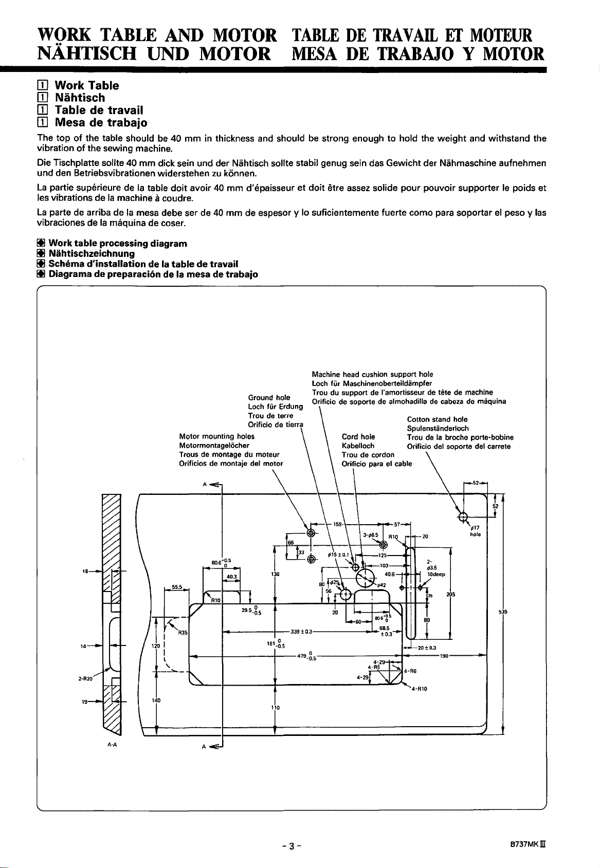
[]] Work Table
Nahtisch
[]]
[]] Table de travail
[]]
Mesa de
The top
vibration
Die Tischplatte sollte
und den Betriebsvibrationen widerstehen
La
les vibrations de
La
vibraciones de
Ill
of
partie superieure de
parte de arriba de
Work
table
Ill Nahtischzeichnung
Ill Schema
Ill Diagrama
trabajo
the table should
of
the sewing machine.
40 mm dick sein und der Nahtisch sollte stabil genug sein das Gewicht der Nahmaschine aufnehmen
Ia
Ia
machine a coudre.
Ia
Ia
processing
d'installation
de
mesa debe ser de
maquina de coser.
preparacion de Ia mesa de
be
40 mm in thickness and should
zu
konnen.
table
doit
avoir
40
mm d'epaisseur et doit etre
40
mm de espesor y lo suficientemente fuerte como para soportar
diagram
de
Ia
table
de
travail
trabajo
MESA
be
DE
TRABAJO Y MOTOR
strong enough to hold the weight and withstand the
assez
solide pour pouvoir supporter
le
el
peso y
poids et
las
Ground hole
Loch
fUr
de
terre
Trou
Orificio de tierra
Motor mounting holes
Motormontagelocher
Trous de montage du moteur
Orificios de montaje del motor
A
Erdung
Machine head cushion support hole
Loch
fUr
Maschinenoberteildampfer
de
Trou du support
Orificio de soporte de almohadilla
Cord hole
Kabelloch
l'amortisseur
Cotton stand hole
Spulenstanderloch
Trou
de
Orificio del soporte del carrete
de
tete de machine
de
cabeza
de maquina
Ia
broche porte-bobine
205
535
110
A-A
A
-3-
8737MKm
Page 16
III Motor
III Motor
III Moteur
III Motor
A
CAUTION/
ACHTUNG/
ATTENTION/
ATENCION
o·
0
o·
0
o·
0
o·
0
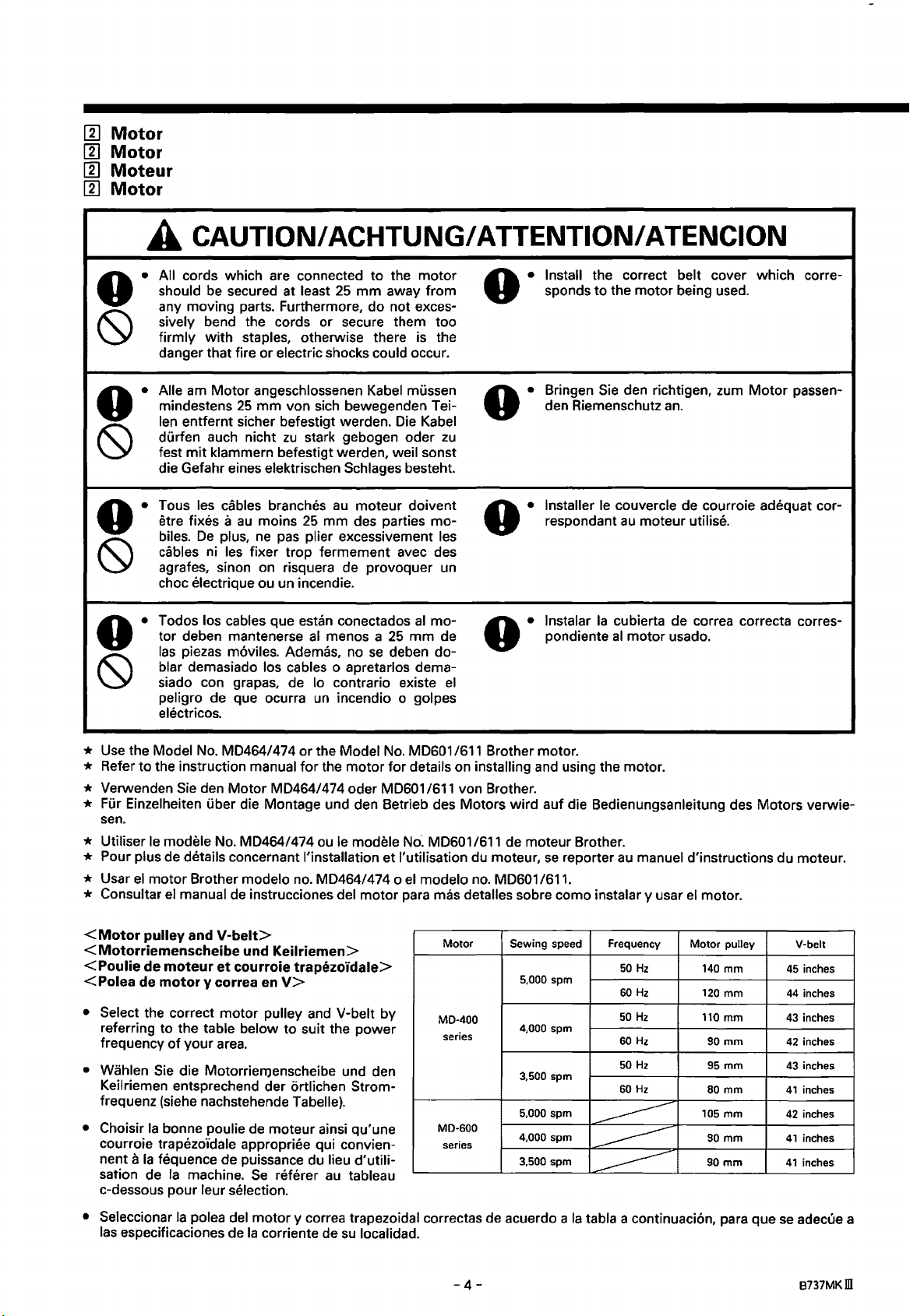
All cords which are connected
should
any moving parts. Furthermore, do not excessively bend the cords or secure them too
firmly with staples, otherwise there is the
danger that fire or
Aile
mindestens
len entfernt sicher befestigt werden.
durfen auch nicht
fest
die Gefahr eines
Taus les cables branches
etre fixes a
biles.
cables
agrafes, sinon on risquera de provoquer
choc electrique ou un incendie.
Todos los cables que estan conectados
tor deben mantenerse
las
blar demasiado los cables o apretarlos demasiado con grapas, de lo contrario existe
peligro de que ocurra
electricos.
be
secured at least
electric shocks could occur.
am
Motor angeschlossenen Kabel mussen
25
mm
von sich bewegenden Tei-
zu
mit
klammern befestigt werden, wei I sonst
au
plus,
moins
ne
De
ni les fixer trap fermement avec des
piezas m6viles. Ademas, no
stark gebogen oder
elektrischen Schlages besteht.
25
pas
plier excessivement les
al
un
to
the motor
25
mm
away from
Die
Kabel
zu
au
moteur doivent
mm des parties mo-
un
al
menos a
se
incendio o golpes
mo-
25
mm
deben do-
de pondiente
el
o • Install the correct belt cover which
sponds to the motor being used.
Bringen Sie den richtigen, zum Motor passen-
o·
o·
o·
den Riemenschutz
Installer
respondant
lnstalar
le
couvercle de courroie adequat cor-
Ia
cubierta de correa correcta corresal
an.
au
moteur utilise.
motor usado.
corre-
* Use the Model
* Refer to the instruction manual
* Verwenden
No.
MD464/474
Sie
den Motor MD464/474 oder
or
the Model
for
the motor for details on installing and using the motor.
No.
MD601
MD601
/611 von Brother.
/611 Brother motor.
* Fur Einzelheiten uber die Montage und den Betrieb des Motors wird auf die Bedienungsanleitung des Motors verwie-
sen.
* Utiliser
* Pour plus de details concernant !'installation et I' utilisation du moteur,
* Usar
* Consultar
<Motor
<Motorriemenscheibe und Keilriemen>
<Poulie
<Po
• Select the correct motor pulley and V-belt by
referring to the table below to suit the power
frequency
• Wahlen
Keilriemen entsprechend der ortlichen Stromfrequenz (siehe nachstehende Tabelle).
•
Choisir
courroie trapezo"idale appropriee qui convien-
nent a
sation de
c-dessous pour leur selection.
le
modele No. MD464/474 ou
el
motor Brother modelo
el
manual
pulley and
de moteur
lea de motor y correa
of
your
Sie
die Motorriemenscheibe und den
Ia
bonne poulie de moteur ainsi qu'une
Ia
fequence de puissance du lieu d'utili-
Ia
de
V-belt>
et
courroie trapezoidale>
area.
machine.
no.
instrucciones del motor para mas detalles sobre como instalar y usar
en
V>
Se
referer
le
modele
MD464/474 o
au
tableau
No~
MD601/611 de moteur Brother.
el
modelo
Motor
MD-400
series
MD-600
series
no.
MD601/611.
se
reporter
Sewing speed
5,000 spm
4,000 spm
3,500 spm
5,000 spm
4,000 spm
3,500 spm
au
manuel d'instructions du moteur.
el
motor.
Frequency
50
Hz
60
Hz
50
Hz
60
Hz
50
Hz
60Hz
~
---------
Motor
140 mm
120 mm
110
90
95 mm
80 mm
105 mm
90
90
pulley
mm
mm
mm
mm
---------
V-belt
45
44
43
42
43
41
42
41
41
inches
inches
inches
inches
inches
inches
inches
inches
inches
• Seleccionar
las
especificaciones de
Ia
polea del motor y correa trapezoidal correctas de acuerdo a
Ia
corriente de
su
localidad.
-4-
Ia
tabla a continuaci6n, para que
se
adecue a
8737MKm
Page 17
INSTALLATION
MONTAGE
A
CAUTION/
ACHTUNG
The sewing machine should only be installed
by a qualified technician.
Ask your Brother dealer
cian for any electrical
be
done.
The sewing machine weighs more than
The installation should be carried out by
or more people.
Die
Nahmaschine darf nur von einem qualifi-
zierten Fachmann montiert werden.
Falls
Elektrikerarbeiten gemacht werden mus-
sen,
wenden Sie sich
oder
an
einen qualifizierten Elektriker.
Weil die Nahmaschine mehr
sind zur Montage mindestens zwei Personen
notwendig.
ITJ
Installing the machine head
or
a qualified electri-
work
that may need to
an
lhren Brother-Handler
als
37
kg
37
kg.
two
wiegt,
Do
not connect the power cord until installa-
tion
is
operate
which could result in injury.
Be
connection
shocks
Install the belt cover to the machine head.
SchlieBen
schlossener Montage
unbeabsichtigte Betatigung des Pedals die
Maschine
verursachen
Erden
geerdeter Maschine besteht die Gefahr eines
elektrischen Schlages.
Bringen
oberteil
complete, otherwise the machine will
if
the treadle
sure to connect the ground. If the ground
is
will result.
Sie
das Netzkabel erst nach abge-
in
Gang gesetzt und Verletzungen
kann.
Sie
die Maschine unbedingt.
Sie den Riemenschutz am Maschinen-
an.
is
pressed by mistake,
not secure, serious electric
an,
weil sonst durch eine
Bei
falsch
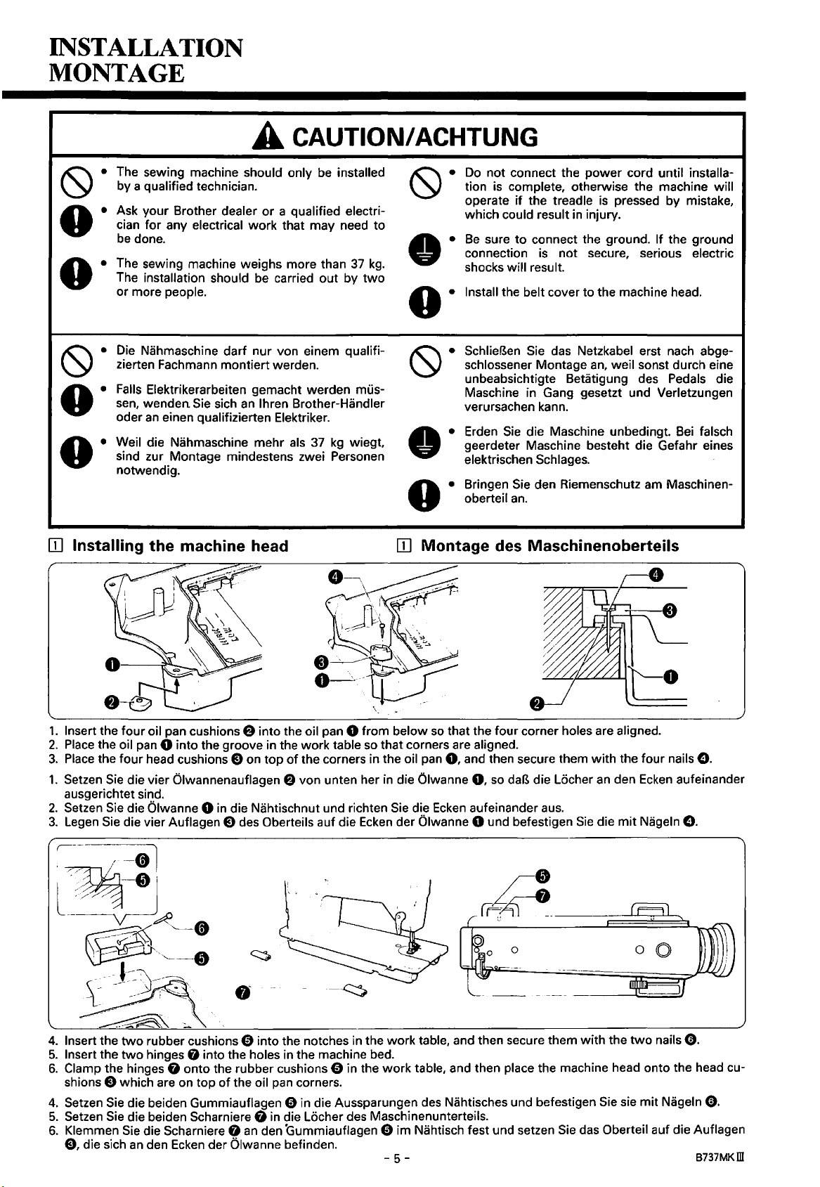
1.
Insert the four oil pan cushions 8 into the oil pan 0 from below
2.
Place
3.
1.
2.
3.
the oil pan 0 into the groove
Place
the four head cushions
Setzen
Sie
ausgerichtet sind.
Setzen
Sie
Legen
Sie
die vier Auflagen
~
r-~<tl
die vier Olwannenauflagen 8 von unten her
die Olwanne 0
in
in
E)
die Nahtischnut und richten
E)
the work table
on top of the corners in the oil
des Oberteils auf die
so
Ecken
that corners are aligned.
in
so
that the four corner holes are aligned.
pan
0,
and then secure them with the four nails
die Olwanne
Sie
die
der Olwanne 0 und befestigen
Ecken
0,
so
daB
aufeinander a
l~~
~
~··'--8
~---~
-.
4.
Insert the
5.
Insert the
6.
Clamp the hinges 0 onto the rubber cushions 0 in the work table, and then place the machine head onto the head cu-
shions e which are on top
4.
Setzen
5.
Setzen
6.
Klemmen
E),
two
two
Sie
Sie
Sie
die sich
·'---0
--
:
\----~
~
rubber cushions 0 into the notches in the work table, and then secure them with the
hinges 0 into the holes
die beiden Gummiauflagen 0 in die Aussparungen des Nahtisches und befestigen Sie sie mit Nageln
die beiden Scharniere 0
die Scharniere 0
an
den
'
l
'
'
of
the oil
an
Ecken
der Olwanne befinden.
in
pan
in
die Locher des Maschinenunterteils.
den Gummiauflagen 0 im Nahtisch fest und setzen
·~~
the machine bed.
corners.
-5-
die Locher
us.
Sie
Sie
das
e.
an
den
Ecken
aufeinander
die mit Nageln
two
nails
e.
e.
e.
Oberteil auf die Auflagen
B737MKill
Page 18
INSTALLATION
INSTALACION
L'installation de
exclusivement
Pour
tout
que, s'adresser a un concessionnaire Brother
ou
La
tallation necessite done
personnes ou plus.
La
nal especializado.
Consultar a
cista
cidad que
La
instalaci6n debe ser realizada por dos o mas
personas.
travail concernant le systeme electri-
a un electrician qualifie.
machine a coudre pese plus de
maquina debe ser instalada solo por perso-
calificado por cualquier trabajo de electri-
maquina de coser pesa mas de
[[) Installation de
A ATTENTION/ A
Ia
machine
a un technician qualifie.
le
su
distribuidor Brother o
se
debiera realizar.
Ia
tete
de machine [[) lnstalaci6n de
doit
etre confiee
37
kg.
un
37
L'ins-
electri-
kg.
La
concours de deux
TEN
CION
Ne
pas brancher le cordon d'alimentation
avant d'avoir termine
machine risquera de
enfonce
causer des blessures.
Veiller a bien brancher
le
aura risque d'electrocution grave.
Installer le couvercle de courroie sur
machine.
No conectar
ber completado
Ia
descuido
sultar
Asegurarse de hacer
conexi6n a tierra no fuera segura,
peligro de sufrir golpes electricos serios.
lnstalar
Ia
accidentellement
branchement de terre n' est pas bien fait, il y
el
cable de alimentaci6n hasta ha-
maquina podria comenzar a funcionar
en
heridas.
Ia
maquina.
Ia
se
pisara
cubierta de
Ia
cabeza de
!'installation, sinon
se
mettre
en
Ia
pedale,
Ia
machine a
instalaci6n, de lo contrario
el
pedal, lo que podria re-
Ia
conexi6n a tierra.
Ia
correa
en
Ia
marche si on
et
done de
Ia
terre. Si
Ia
tete de
si
por
Si
se
corre
Ia
cabeza de
maquina
Ia
Ia
el
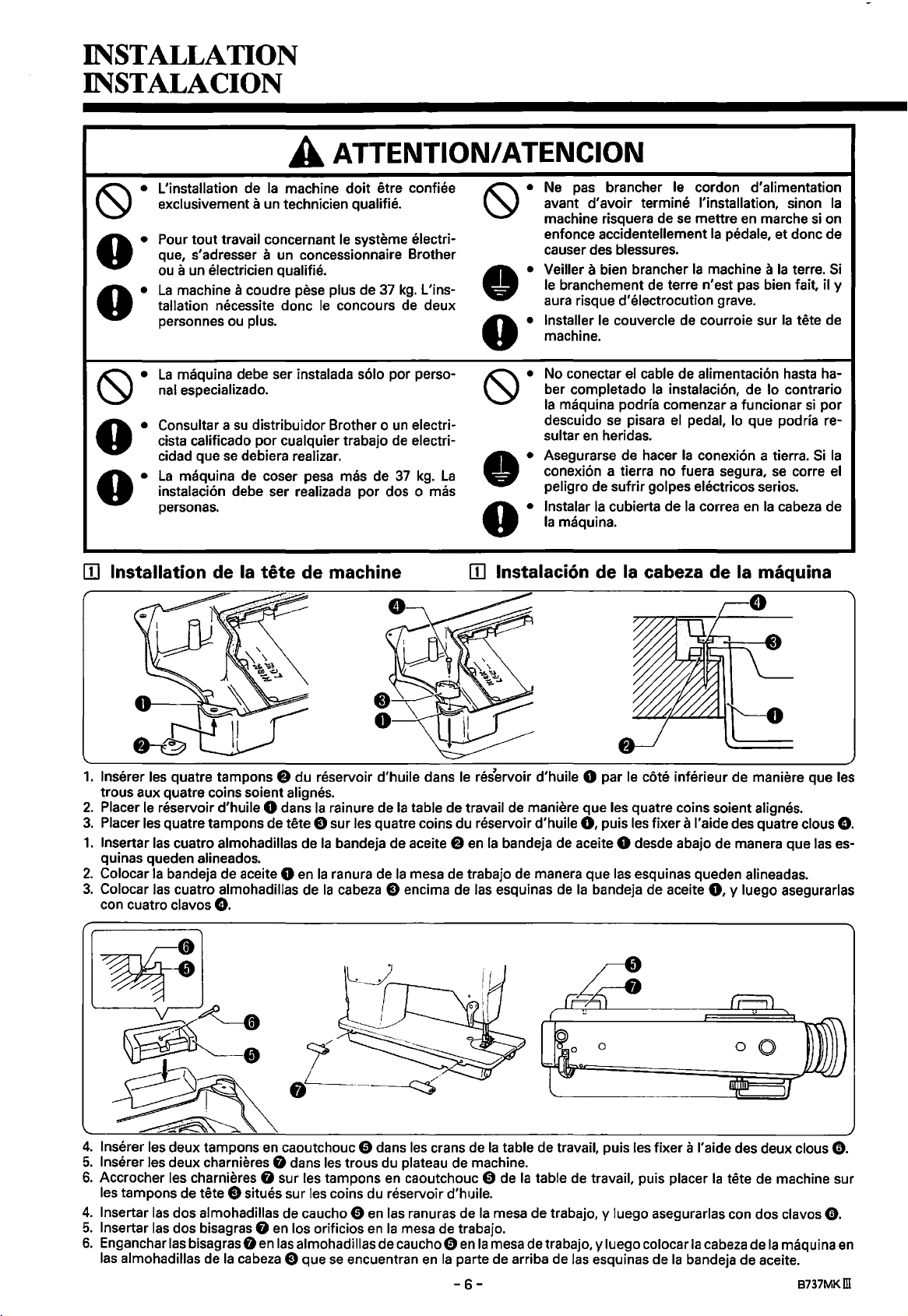
1.
lnserer les quatre tampons e du reservoir d'huile dans le reservoir d'huile 0 par le cote inferieur de maniere que les
trous aux quatre coins soient alignes.
2.
Placer le reservoir d'huile 0 dans
3.
Placer les quatre tampons de tete
1.
lnsertar las cuatro almohadillas de
quinas queden
2.
Colocar
3.
Colocar las cuatro almohadillas de
con cuatro
4.
lnserer les deux tampons
5.
lnserer les deux charnieres 0 dans les trous du plateau de machine.
6.
Accrocher les charnieres 0 sur les tampons en caoutchouc 0 de
les tampons de tete e situes sur les coins du reservoir d'htJile.
4.
lnsertar
5.
lnsertar
6.
Enganchar las bisagras 0
las almohadillas de
alineados.
Ia
bandeja de aceite 0
clavos
e.
en
las
dos almohadillas de caucho 0
las
dos bisagras 0
en
Ia
cabeza
Ia
rainure de
E)
sur les quatre coins du reservoir d'huile
Ia
bandeja de aceite
en
Ia
ranura de
Ia
cabeza
caoutchouc 0 dans les crans de
en
los orificios
las almohadillas de caucho 0
E)
que
se
encuentran
Ia
table de travail de maniere que les quatre coins soient alignes.
f)
Ia
mesa de trabajo de manera que las esquinas queden alineadas.
E)
encima de las esquinas de
en
las ranuras de
en
Ia
mesa de trabajo.
en
Ia
parte de arriba de las esquinas de
-6-
en
Ia
bandeja de aceite 0 desde abajo de manera que las es-
Ia
table de travail, puis les fixer a I' aide des deux clous
Ia
table de travail, puis placer
Ia
mesa de trabajo, y luego asegurarlas con dos clavos
en
Ia
mesa de trabajo, y luego colocar
0,
puis les fixer a I' aide des quatre clous
Ia
bandeja de aceite
0,
y luego asegurarlas
oo
Ia
tete de machine sur
Ia
cabeza de
Ia
bandeja de aceite.
Ia
e.
maquina
B737MKill
e.
e.
en
Page 19
[1]
Installing
[1]
Montage der Kniehebel
the
knee lifter assembly
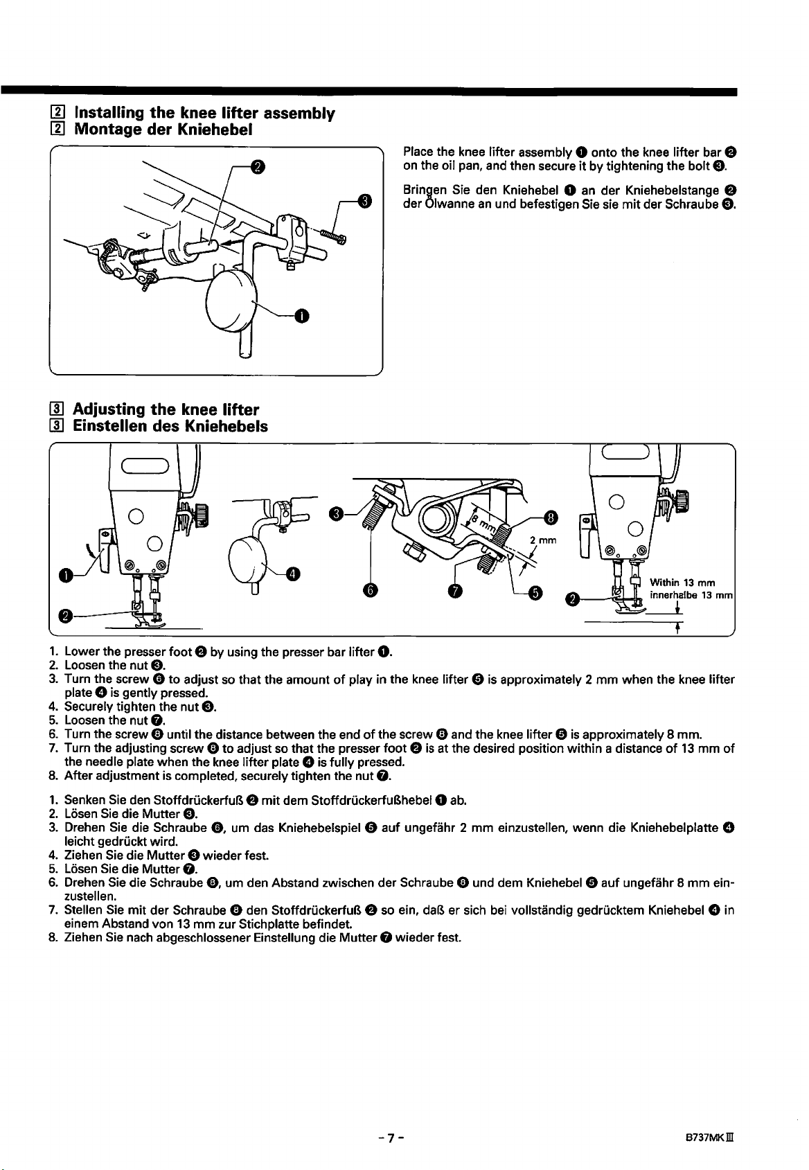
Place the knee lifter assembly 0 onto the knee lifter bar 8
on the oil pan, and then secure
it
by tightening the bolt
e.
II]
Adjusting
II]
Einstellen des Kniehebels
the
knee lifter
Bringen Sie den Kniehebel 0
der Olwanne
an
und befestigen Sie sie
an
der
Kniehebelstange 8
mit
der Schraube
e.
1.
Lower the presser
2.
Loosen the nut
3.
Turn the screw 0
plate
4.
5.
6.
7.
8.
1.
2.
3.
4.
5.
6.
7.
8.
0 is gently pressed.
Securely tighten the nut
Loosen the nut
Turn the screw 0 until the distance between the end
Turn the adjusting screw 0 to adjust so that the presser
the needle plate when the knee lifter plate 0 is
After adjustment is completed, securely tighten the nut
Senken Sie den Stoffdri.ickerfuB 8
Losen Sie die Mutter
Drehen Sie die Schraube
Ieicht gedri.ickt wird.
Ziehen Sie die
Losen Sie die Mutter
Drehen Sie die Schraube
zustellen.
Stellen Sie
einem Abstand von 13
Ziehen Sie nach abgeschlossener Einstellung die Mutter G wieder fest.
foot
8 by using the presser bar lifter
e.
to
adjust so that the amount
e.
G.
mit
dem Stoffdri.ickerfuBhebel 0
e.
0,
urn das Kniehebelspiel 0 auf ungefahr 2
Mutter
e wieder fest.
G.
0,
urn den Abstand zwischen der Schraube 0 und dem Kniehebel 0 auf ungefahr 8
mit
der Schraube 0 den Stoffdri.ickerfuB 8
mm
zur Stichplatte befindet.
0.
of
play in the knee lifter 0 is approximately 2
of
the screw 0 and the knee lifter 0
fully
foot 8 is
pressed.
G.
so
ein, daB er sich bei vollstandig gedrucktem Kniehebel 0 in
mm
when the knee lifter
is
at the desired position within a distance
ab.
mm
einzustellen, wenn die Kniehebelplatte 8
approximately 8 mm.
of
13
mm
mm
of
ein-
-7-
B737MKill
Page 20
[!]
Installation de l'ensemble de releveur
[!]
lnstalacion del
con"junto
del levantador de rodilla
au
genou
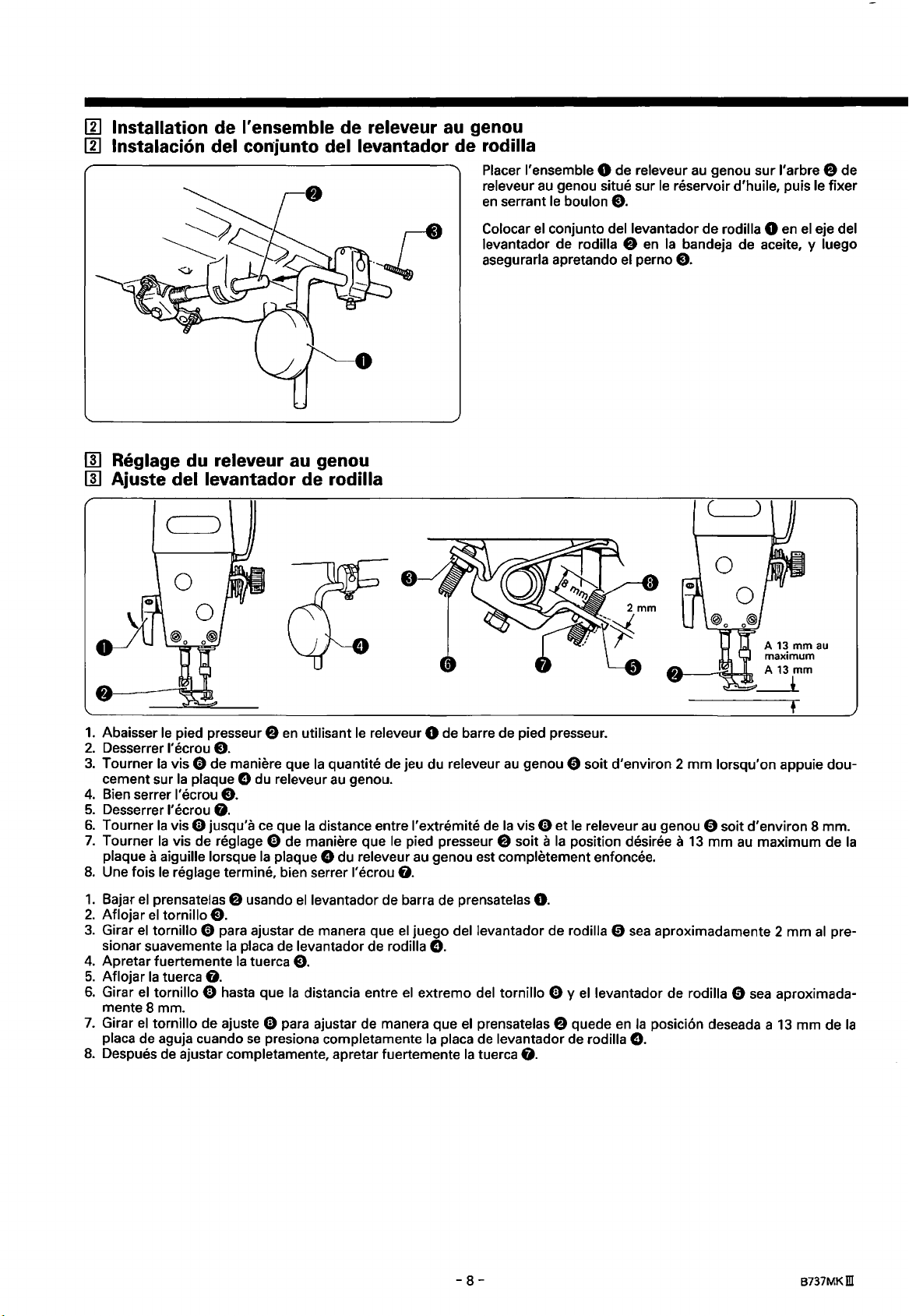
Placer !'ensemble 0 de releveur
releveur
en
au
serrant
genou situe sur
Je
boulon
e.
au
le
genou sur l'arbre 8 de
reservoir d'huile, puis le fixer
II]
Reglage du releveur
II]
Ajuste del levantador de rodilla
au
genou
Colocar
Jevantador de rodilla
asegurarla apretando el perno
el
con junto del levantador de rodilla 0
8
en
Ia
bandeja de aceite, y
en
e.
(__)
el
eje del
Juego
1.
Abaisser
2.
Desserrer I' ecrou
3.
Tourner
cement sur
4.
Bien serrer I' ecrou
5.
Desserrer l'ecrou
6.
Tourner
7.
Tourner
plaque a aiguille lorsque
8.
Une fois
1.
Bajar
2.
Aflojar
3.
Girar
sionar suavemente
4.
Apretar fuertemente
5.
Aflojar
6.
Girar
mente8
7.
Girar
placa de aguja cuando
8.
Despues de ajustar completamente, apretar fuertemente
Je
pied presseur 8
en
utilisant
Je
releveur 0 de barre de pied presseur.
e.
Ia
vis 0 de maniere que
Ia
plaque 0 du releveur
Ia
quantite de jeu du releveur
au
genou.
e.
0.
Ia
vis 0 jusqu'a
Ia
vis de reglage 0 de maniere que le pied presseur 8 soit a
Je
reglage termine, bien serrer l'ecrou G.
el
prensatelas 8 usando ellevantador de barra de prensatelas
el
tornillo
el
tornillo 0 para ajustar de manera que
Ia
tuerca
el
tornillo 0 hasta que
mm.
el
tornillo de ajuste 0 para ajustar de manera que
e.
0.
ce
que
Ia
distance entre J'extremite de
Ia
plaque 0 du releveur
Ia
placa de levantador de rodilla
Ia
tuerca
e.
Ia
distancia entre
se
presiona completamente
au
el
juego del levantador de rodilla 0
el
au
genou 0 soit d'environ 2
Ia
vis 0 et le releveur
Ia
genou est completement enfoncee.
position desiree a
0.
0.
extrema del tornillo 0 y
el
Ia
prensatelas 8 quede
placa de Jevantador de rodilla
Ia
tuerca G.
el
Jevantador de rodilla 0
en
mm
Jorsqu'on appuie dou-
au
genou 0 soit d'environ 8 mm.
13
mm
au
maximum de
sea
aproximadamente 2
sea
aproximada-
Ia
posicion deseada a
13
0.
mm
mm de
al
Ia
pre-
Ia
-8-
B737MKm
Page 21
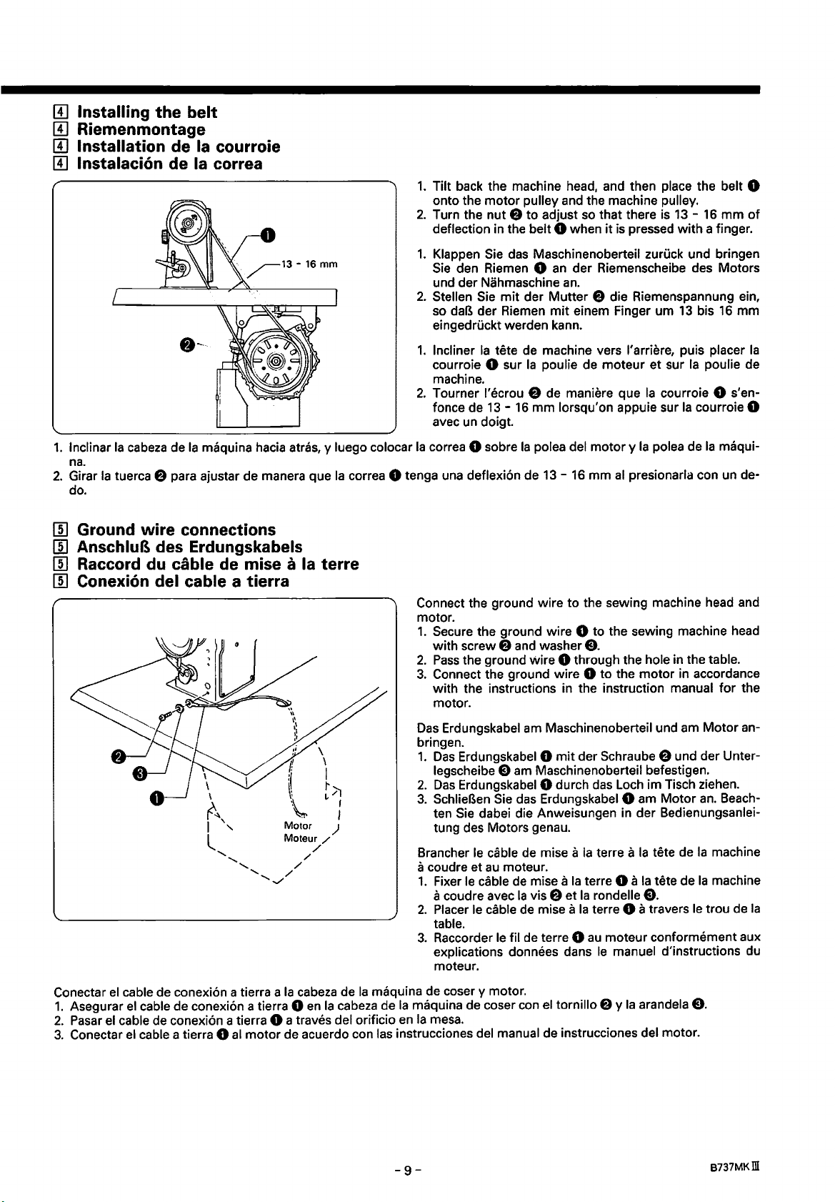
[!] Installing the belt
[!] Riemenmontage
[!] Installation de Ia courroie
[!]
lnstalaci6n de Ia correa
-~--
1.
lnclinar
na.
2.
Girar
do.
Ia
cabeza
Ia
tuerca 8 para ajustar de manera que
de
Ia
maquina hacia atras, y luego colocar
1.
Tilt back the machine head, and then place the belt 0
onto the
2.
Turn the nut 8 to adjust so that there is
deflection in the belt 0 when
1.
Klappen Sie das Maschinenoberteil zuruck und bringen
Sie den Riemen 0
und der Nahmaschine
2.
Stellen Sie
so
eingedruckt werden kann.
1.
Incliner
courroie 0 sur
machine.
2.
Tourner l'ecrou 8 de maniere que
fonce de
avec un doigt.
Ia
correa 0 sobre
Ia
correa 0 tenga una deflexi6n de 13 - 16
motor
pulley and the machine pulley.
mit
daB der Riemen
Ia
der
tete de machine vers l'arriere, puis placer
Ia
13-
16
mm
Ia
polea del
Mutter
mit
poulie de moteur
13-
it
is pressed with a finger.
an
der Riemenscheibe des Motors
an.
16
8 die Riemenspannung ein,
einem Finger urn
lorsqu'on appuie sur
motor y Ia
mm
al
presionarla con un de-
13
bis 16
et
sur
Ia
poulie de
Ia
courroie 0 s'en-
Ia
courroie 0
polea de
Ia
mm
of
mm
maqui-
Ia
00
Ground wire connections
00
AnschluB des Erdungskabels
00
Raccord
00
Conexion del cable a tierra
du
cable de mise a Ia terre
Connect the ground wire to the sewing machine head and
motor.
1.
Secure the ground wire 0 to the sewing machine head
with screw
2.
Pass
3.
Connect the ground wire 0
with the instructions in the instruction
motor.
Das
Erdungskabel am Maschinenoberteil und am
bringen.
1.
Das
legscheibe e am Maschinenoberteil befestigen.
2.
Das
3.
SchlieBen Sie das Erdungskabel 0 am
ten
Sie dabei die Anweisungen in der Bedienungsanlei-
tung des Motors genau.
Brancher
a coudre et
1.
Fixer
a coudre avec
2.
Placer le cable de mise a
table.
3.
Raccorder le til de terre 0
explications donnees dans
moteur.
e and washer
the ground Wire 0 through the hole in the table.
Erdungskabel 0
Erdungskabel 0 durch das Loch im Tisch ziehen.
le cable de mise a
au
moteur.
le
cable de mise a
Ia
vis
e.
to
the motor in accordance
manual
mit
der Schraube 8 und der Unter-
Motor
Ia
terre a
Ia
tete de
Ia
f)
terre 0 a
et
Ia
rondelle
Ia
terre 0 a travers le trou de
au
le
Ia
tete de
e.
moteur conformement aux
manuel d'instructions du
for
Motor
an.
Beach-
Ia
machine
Ia
machine
the
an-
Ia
Conectar
1.
2.
3.
el
Asegurar
Pasar
el
Conectar
cable de conexi6n a tierra a
el
cable de conexi6n a tierra 0
cable de conexi6n a tierra 0 a traves del orificio
el
cable a tierra 0
al
Ia
cabeza de
en
motor
de acuerdo con las instrucciones del manual de instrucciones del motor.
Ia
Ia
cabeza de
maquina de coser y motor.
Ia
maquina de coser con
en
Ia
mesa.
-9-
el
tornillo 8 y
Ia
arandela
e.
B737MKill
Page 22

II]
Installing the bobbin winder
[!]
Montage des Spulers
II]
Installation du bobineur de canette
II]
lnstalaci6n de
Ia
bobinadora
•
3.
Installer
4.
Tirer le bras 0 du presseur de canette vers l'arriere
bineur de canette
le
bobineur de canette sur
et
Ia
courroie
Ia
table de travail a l'aide des deux vis
e.
1.
Push down the bobbin presser arm 0
2.
Place
the bobbin winder wheel
belt e by approximately 5 mm, and then place the bob-
it
bin winder so that
work table.
3.
Install the bobbin winder
screws
4.
winder wheel e and the belt
1.
2.
e.
Pull the bobbin presser arm 0 back and check that there
is approximately 8
DrOcken
unten. .
Positionieren
Sie
den Spulenarm 0
Sie
e um ungefahr 5
den Spuler parallel zur Riemenoffnung im Nahtisch
3.
Befestigen Sie den Spuler
am Nahtisch.
4.
Ziehen
Sie,
dem Riemen e ungefahr 8
1.
Abaisser
2.
Placer
qu'elle pousse
cer
courroie dans
Sie
den Spulenarm 0
ob der Abstand zwischen dem Spulerrad
au
maximum
Ia
roue
le
bobineur de canette parallelement
Ia
is parallel
mm
das Spulerrrad
mm
fJ
du bobineur de canette de maniere
Ia
courroie e d'environ 5 mm, puis pla-
table de travail.
8.
et
verifier qu'il y ait un ecart d'environ 8
as
far
as
it
f)
so
that
with
the belt hole in the
to
the work table with the
of
clearance between the bobbin
will go.
it
pushes the
two
e.
so
weit wie moglich nach
f),
so
daB der Riemen
eingedrOckt wird und richten Sie
mit
den beiden Schrauben 8
zurOck
mm
le
bras 0 du presseur de canette.
mm
und kontrollieren
betragt.
entre
Ia
roue
au
2)
aus.
fJ
und
trou de
du bo-
1.
Empujar hacia abajo tanto como
2.
Colocar
bobinadora de manera que quede paralela con
3.
lnstalar
4.
Tirar del brazo presionador de
entre
Ia
rueda de
Ia
bobinadora
Ia
rueda de
Ia
bobinadora
en
Ia
bobinadora
Ia
sea
posible
f)
de manera que empuje
mesa de trabajo con los dos tornillos
Ia
bobina 0 hacia atras y verificar que exista una separaci6n de aproximadamente 8 mm
fJ
y
Ia
correa
el
brazo presionador de
el
orificio de
Ia
e.
Ia
bobina
0.
Ia
correa e aproximadamente 5 mm, y luego colocar
correa
en
Ia
mesa de trabajo.
8.
Ia
-10-
B737MKID
Page 23

III Installing the belt cover
III Montage des Riemenschutzes
III Installation
III lnstalacion de
du
couvercle de courroie
Ia
cubierta de Ia correa
0
1.
Loosen the three screws 0 on the machine side plate by 4-5 turns.
2.
Tilt back the machine head, align the groove in the belt cover 8 with the stud
curely tighten screw 0-A only.
1.
Losen Sie die drei Schrauben 0
2.
Klappen Sie das Maschiennoberteil zuruck, richten
Schrauben
1.
Desserrer les trois vis 0 de
2.
Incliner
les trois vis
1.
Aflojar los tres tornillos 0 de
2.
lnclinar
tornillos
0
aus
und ziehen Sie nur die Schraube 0-A fest.
Ia
tete de machine vers l'arriere, aligner
0,
puis serrer fermement
Ia
cabeza de
0,
y luego apretar fuertemente solo
Ia
maquina hacia atras, alinear
an
der seitlichen Maschinenplatte urn 4 bis 5 Umdrehungen.
Ia
plaque laterale de machine de 4 a 5 tours.
Ia
vis 0-A seulement.
Ia
placa lateral de
Sie
die Nut des Riemenschutzes 8 auf den Zapfen
Ia
raif'lure du couvercle 8 de courroie avec le clou a grosse tete E) et
Ia
maquina 4-5 vueltas.
Ia
ranura de
el
tornillo 0-A.
Ia
cubierta de
0-A
E)
and the three screws
Ia
correa 8 con
el
0,
E)
esparrago
and then se-
und die drei
E)
y los tres
-
11
-
B737MKill
Page 24

3.
Return the machine head to its original position, and
then remove the screw
head.
4.
Align screw
and then place belt cover U 0 onto the machine pulley.
5.
Tighten screws
0-B
0-B,
C)
from the rear
with the groove 0
0-C
and
C)
to
of
the machine
in
belt cover U
secure belt cover U
0.
3.
Richten
fernen
sch
4.
Richten
menschutzes U 0 aus und bringen Sie den Riemenschutz
5.
Ziehen Sie die Schrauben
Riemenschutz U 0
3.
Remettre
retirer
4.
Aligner
courroie
Ia
5.
Serrer les vis
de courroie
3.
Volver
luego quitar
de
4.
Alinear
Ia
0
5.
Apretar los tornillos
bierta de
Sie
das Maschinenoberteil wieder auf und ent-
Sie die Schraube
i nenobertei
U 0
Ia
poulie de machine.
Is.
Sie
die Schraube
an
der Riemenscheibe der Maschine
zu
Ia
tete de machine a
vis
C)
de l'arriere de
Ia
vis
0-B
U,
avec
puis placer
0-B,
U.
Ia
cabeza
Ia
maquina.
el
correa U
en
Ia
polea de
Ia
de
el
tornillo
tornillo
0-B
0,
y luego colocar
Ia
maquina.
correa U
C)
auf der Ruckseite des Ma-
0-B
auf die Nut 0 des
0-B,
0-C
und
C)
befestigen.
sa
position initiale, puis
Ia
tete de machine.
Ia
rainure 0 du couvercle 0 de
le
couvercle 0 de courroie U sur
0-C
et
C)
Ia
maquina a
C)
de
con
Ia
0-B,
0-C
pour fixer
Ia
parte trasera de
ranura 0
Ia
cubierta de
y
C)
le
Ia
posicion original, y
en
Ia
para asegurar
0.
an.
fest, urn den
couvercle 0
Ia
cubierta de
Ia
correa U
0,
Rie-
cabeza
Ia
cu-
6.
Place
belt cover D
by 2 - 3 mm, and then provisionally tighten the
screws0.
6.
2.6
mm
2.6mm 2,6mm
Bringen
Riemenschutz E) und 2 bis 3
Sie
6.
Placer
chevauche
serrer provisoirement les deux vis
6.
Colocar
superponga a
y luego apretar provisional mente los dos
-
12-
Sie
die Schraube 0 provisorisch fest.
le
couvercle G de courroie D de maniere qu'il
Ia
cubierta de
f)
so
that
it
overlaps the belt cover E)
den Riemenschutz D G
le
couvercle e de courroie de 2 - 3 mm, puis
mm
so
an,
daB
uberlappt und ziehen
er den
0.
Ia
Ia
cubierta de
correa D G de manera que
Ia
correa E) unos 2 - 3 mm,
tornillos
8737MKill
0.
two
se
Page 25

X X
7.
Insert the cover 0
belt cover
the groove
8.
Slide the cover 0 down along the groove
D 8
7.
Bringen
Q and belt cover D
of
as
far
as
Sie
die Abdeckung 0 des Riemenschutzes D
of
belt cover D 8
belt cover D
it will go.
8.
8,
in
and then place
8 zwischen dem Riemenschutz Q und dem
menschutz D 8
Riemenschutzes
8.
Schieben
Riemenschutzes
7.
lnserer
entre
courroie
le
le
couvercle Q
D,
8 de courroie
8.
Faire glisser bien a fond
long de
7.
lnsertar
entre
rrea D
de
8.
ra
ble.
Deslizar
Ia
Ia
Ia
cubierta de
8,
Ia
corre~
Ia
de
Ia
cubierta de
an
und setzen Sie sie in die Nutdes
D 8 ein.
Sie
die Abdeckung 0 entlang der Nut des
8 ganz
couvercle 0 du couvercle 8 de courroie D
puis
le
D.
rainure du couvercle 8 de courroie
cubierta 0 de
~·
luego colocarla
D
8.
cubierta 0 hacia abajo a lo largo de
·nach
unten.
de
courroie
placer dans
le
Ia
Ia
correa e y
Ia
correa D 8 tanto como
et
le
Ia
rainure du couvercle
couvercle 0 vers le bas
cubierta de
Ia
cubierta de
en
Ia
ranura de
couvercle 8
Ia
between the
it
into
of
belt cover
Rie-
de
le
D.
correa D 8
Ia
CO-
Ia
cubierta
Ia
ranu-
sea
posi-
9.
Tirer
le
couvercle 8 de courroie D vers soi jusqu'a
couvercle 0 du couvercle 8 de courroie
10.
Serrer completement les deux vis
9.
Tirar
de
Ia
cubierta de
rrea Q y
10.
Apretar fuertemente los dos tornillos
Ia
cubierta 0 de
Ia
correa D 8 hacia adelante hasta que no quede ninguna separaci6n entre
Ia
correa D
D.
0.
(Se
reporter a l'etape
8.
0.
(Consultar
ce
el
qu'il
paso
9.
Pull
belt cover D 8 toward you until there is no clear-
ance
between the belt cover e and the cover 0
cover D
10.
Fully tighten the
9.
Ziehen
dem Riemenschutz
menschutzes D 8 kein Zwischenraum vorhanden ist.
10.
Ziehen
6.)
ne
reste plus d'ecart entre
6.)
6.)
8.
two
screws
Sie
am
Riemenschutz D
Q und der Abdeckung 0 des
Sie
die beiden Schrauben 0 fest. (Siehe Schritt
0.
(Refer to step
le
couvercle Q
8,
so
de
Ia
cubierta de
daB
courroie et
of
belt
6.)
zwischen
Rie-
le
Ia
co-
-
13-
8737MKm
Page 26

[!]
Installing the cotton stand
[!]
Montage des Spulentragers
[!] Installation
de
Ia
broche porte-bobine
[!] lnstalacion del soporte del carrete
Assemble the cotton stand
then
install
it
to the work table.
as
* Securely tighten the nut 0
not move.
Bauen
Sie
zusammen und montieren
* Ziehen
Spulentrager nicht bewegen
den Spulentrager wie in der Abbildung gezeigt
Sie
die Mutter 0 richtig fest,
Sie ihn am Nahtisch.
shown in the illustration, and
so
that the cotton stand does
so
kann.
daB sich der
Assembler
lustration,
Ia
broche porte-bobine comme indique sur !'il-
puis !'installer sur
Ia
table de travail.
* Bien serrer l'ecrou 0 de maniere que
bobine
Armar
y luego instalarlo
* Apretar fuertemente
porte
ne
bouge
pas.
el
soporte del carrete tal como
del carrete no
en
Ia
mesa
Ia
se
mueva.
de trabajo.
tuerca 0
se
de
Ia
broche porte-
indica
en
Ia
manera que
figura,
el
so-
-
14-
B737MKm
Page 27

I]]
Lubrication
I]]
Schmierung
I]]
Lubrification
I]]
Lubricacion
A
CAUTION/
Be
sure to wear protective goggles and gloves when handling the lubricating oil, so that no oil gets into your
eyes or onto your skin, otherwise inflammation can result.
Furthermore, do not drink the
Keep the
oil
out
of
the reach
ACHTUNG/
oil under any circumstances,
of
children.
ATTENTION/
as
ATENCION
it
can
cause vomiting and diarrhoea.
• Tragen Sie zur Handhabung von Schmierol eine Schutzbrille und Schutzhandschuhe. Falls
oder auf die Haut gelangt, konnen sich diese
brechen und
Bewahren
• Veiller a mettre des lunettes et des gants de protection lors de
preserver
De
plus, !'ingestion de l'huile est a proscrire absolument, car elle pourrait causer des vomissements et des
diarrheas.
Ranger l'huile hors de portee des enfants.
• Asegurarse de usar anteojos de seguridad y guantes
aceite lubricante no
Ademas, bajo ningun concepto
Mantener
Durchfall auftreten.
Sie das
les yeux et
el
01
nicht in Reichweite von Kindern auf.
Ia
peau de
sal
pique
aceite lubricante lejos del alcance de los niiios.
tout
contact avec l'huile, et d'eviter
en
ojos o
Ia
se
debe beber aceite lubricants pues pod ria ocasionar v6mitos y diarrea.
Stellen entzunden.
al
piel, de lo contrario podrian resultar inflamados.
Bei
irrtumlicher Einnahme von
Ia
manipulation d'huile lubrifiante, afin de
tout
risque d'inflammation.
manipular aceites lubricantes, de manera que
01
* Use only the lubricating oil (Nisseki Sewing Lube
specified by Brother.
Tilt back the machine head and
oil until the oil level reaches the
*
If
the oil level drops below the LOW mark, add more lu-
bricating oil.
slowly pour in lubricating
HIGH
mark.
* Verwenden Sie nur das von Brother vorgeschriebene
Schmierol (Nisseki Sewing Lube
Schwenken Sie das Nahmaschinenoberteil zuruck und
Ien Sie Iangsam
"HIGH" steht.
01
ein, bis der Olstand
10).
an
* Falls der Qlstand unter die Markierung "LOW" abfallt,
muB
61
nachgefullt werden.
in die Augen
01
kann Er-
el
10)
der Markierung
fUI-
* Utiliser seulement l'huile de lubrification (Nisseki Sewing Lube 1
Incliner
teigne le repere
*
* Usar solo aceite lubricants (Nisseki Sewing Lube 1
lnclinar
ta
*
Ia
tete de machine vers l'arriere et verser doucement l'huile de lubrification jusqu'a
Si
le
niveau d'huile baisse au-dessous du repere
Ia
Ia
marca
Si
el
nivel de aceite baja por debajo de
HIGH.
cabeza de
HIGH.
Ia
maquina hacia atras y volcar lentamente
Ia
marca
LOW,
rajouter de l'huile de lubrification.
0)
especificado por Brother.
LOW,
el
agregar mas aceite lubricants.
-
15-
0)
recommandee par Brother.
aceite lubricante hasta que
ce
que le niveau d'huile at-
el
nivel de aceite llegue has-
8737MKm
Page 28

1IID
Checking
1]]1
Kontrolle
1]]1
Verification
1]]1
Verificacion de Ia
~·
the
der
A
CAUTION/
Do
not touch any of the moving parts or place any objects against the machine while sewing,
sult in personal injury
machine
pulley
rotating
direction
Nahmaschinen-Riemenscheibendrehrichtung
du
sens
de
rotation
direccion
ACHTUNG/
or
damage
de Ia poulie
de
rotacion
to
the machine.
de
machine
de
Ia polea de Ia maquina
ATTENTION/
ATENCION
as
this may re-
• Beruhren
sich verletzen konnen und die Nahmaschine beschadigt werden kann.
• Ne toucher aucune des parties mobiles
non on risquera de
• No tocar ninguna de
sultar
1.
lnserer
demarche.
2.
Enfoncer
*
Si
tions du moteur.
Ia
le
sens de rotation est inverse,
Sie
keine sich bewegenden Teile und halten
se
blesser ou d'endommager
las
piezas m6viles o colocar ningun objeto sobre
en
heridas o
fiche du cordon d'alimentation dans
Ia
pedale et verifier que
Ia
maquina pod
le
sens de rotation de
le
remettre dans
ria
Sie
auch keine Gegenstande
ni
ne
placer aucun objet contre
Ia
machine.
resultar danada.
1.
Insert the power cord plug into the wall outlet,
turn on the power switch.
2.
Depress the treadle and check that the direction
of
the machine pulley matches the direction
tion
arrowO.
* If the direction
tion
of
rotation to the correct direction while referring to
the instruction manual
1.
SchlieBen
und schalten
2.
Drucken
Drehrichtung der Nahmaschinen-Riemenscheibe der
Pfeilrichtung 0 entspricht.
*
Bei
sprechend der Bedienungsanleitung des Motors geandert werden.
Ia
prise murale, puis mettre l'interrupteur d'alimentation sur laposition
Ia
poulie de machine corresponde
le
sens de rotation correct
Sie
Sie
falscher Drehrichtung muB die Drehrichtung ent-
Ia
machine
Ia
maquina
of
rotation
for
den Netzstecker
Sie
den Netzschalter
das
Pedal
tout
en
se
an
solche Teile, weil
en
cours de couture, si-
al
coser, pues podria re-
and
is
reversed, change the direc-
the motor.
an
einer Steckdose
ein.
und kontrollieren
au
sens de
reportant
au
Sie,
Ia
fleche
0.
manuel d'instruc-
of
ob die
Sie
then
rota-
of
the
an
1.
lnsertar
2.
Pisar
flecha
*
Si
de instrucciones del motor.
el
enchufe del cable
el
pedal y verificar que
0.
Ia
direcci6n de rotaci6n esta invertida, cambiar
de
alimentaci6n
Ia
direcci6n de rotaci6n de
en
el
tomacorriente de
Ia
polea de
Ia
direcci6n de rotaci6n a
Ia
pared, y luego conectar
Ia
maquina esta de acuerdo con
Ia
direcci6n correcta consultando
el
interrupter principal.
Ia
direcci6n de
el
manual
Ia
-
16-
8737MKill
Page 29

PREPARATION
BEFORE
SEWING
PREPARATIFS
AVANT
LA
COUTURE
VORBEREITUNGEN
ITJ
Removing
ITJ
Herausnehmen
ITJ
Retrait de
ITJ
Manera de sacar Ia caja de Ia bobina
the
bobbin case
der
Ia
boite a canette
ZUM
Spulenkapsel
A CAUTION/ ACHTUNG/ ATTENTION/ A
Turn
off
treadle is pressed by mistake, which could result in injury.
• Schalten Sie den Netzschalter
konnen, wenn sich die Maschine durch unbeabsichtigtes Drucken des Pedals in Gang setzt.
• Mettre l'interrupteur d'alimentation
risquera de
•
Desconectar
menzar a funcionar si
the power switch before removing the bobbin case, otherwise the machine may operate
vor
se
mettre
el
en
marche si on enfonce accidentellement
interrupter principal antes de sacar
por
descuido
NAllEN
dem Herausnehmen der Spulenkapsel aus, weil Verletzungen entstehen
en
position d'arret avant de retirer
se
pisara
PREPARATIVOS
Ia
Ia
el
caja de
pedal, lo que podrfa resultar
1.
2.
3.
Ia
bobina, de
Turn the machine pulley to raise the needle until
above the needle plate.
Pull the latch 0
remove the bobbin
The bobbin
leased.
Ia
pedale, et done de causer des blessures. .
of
f)
will come out when the latch 0 is re-
ANTES
TEN
boite a canette, sinon
Jo
contrario
en
heridas.
the bobbin case upward and then
case.
DE
COSER
CION
Ia
machine
Ia
maquina podrfa co-
if
the
it
is
1.
Tourner
guille.
2.
Sou1ever
3.
La
1.
Girar
2.
Tirar del seguro 0 de
3.
La
Ia
le verrou 0 de
canette
Ia
polea de
bobina
poulie de machine de maniere a relever l'aiguille jusqu'a
f)
sortira Jorsqu'on relache le verrou
f)
saldra hacia afuera cuando
For thick materials
Fur
dicke Stoffe
Pour les tissus epais
Para telas gruesas
Ia
boite a canette puis deposer
Ia
maquina para levantar
Ia
caja de
Ia
bobina y
1.
Heben Sie die Nadel durch Drehen
riemenscheibe bis
2.
Ziehen Sie die Lasche 0 nach oben und nehmen Sie die
Spulenkapsel heraus.
3.
Die Spule
loslassen.
Ia
boite a canette.
0.
Ia
aguja hasta quede encima de
Juego
sacar
Ia
caja de
se
libere
el
seguro
0.
uber die Stichplatte
f)
fallt heraus, wenn Sie die Sperrlasche 0
ce
qu'elle soit placee au-dessus de
Ia
placa de aguja.
Ia
bobina.
der
Nahmaschinen-
an.
Ia
plaque a ai-
-
17-
B737MKm
Page 30

[11
Winding the lower thread
[11
Aufwickeln des Unterfadens
Ill Bobinage du fil inferieur
III
Bobinado del hilo inferior
A CAUTION/ ACHTUNG/ ATTENTION/ A
Do
~-
{
X
not touch any
thread,
• Beruhren Sie beim Aufwickeln des Unterfadens keine sich bewegenden Teile und halten
genstande
•
Ne
ferieur, sinon on risquera de
• No tocar ninguna de las piezas m6viles o colocar ningun objeto contra
ferior, pues podria
80%
Thread winding amount
aufgewickelte Fadenmenge
Ouantite de bobinage de fil
Cantidad de hilo enrollado
0
as
this may result in personal injury
an
toucher aucune des parties mobiles ni
X
* Urn mehr Faden auf die Spule 0 aufzuwickeln, konnen Sie die Schraube 0 anziehen.
Hinweis:
1.
Mettre l'interrupteur d'alimentation sur
2.
Placer
3.
Enrouler le fil de plusieurs tours autour de
4.
Enfoncer
5.
Une fois que le bobinage du fil de canette est termine, deposer
tion.
Wickeln Sie den Faden nur bis
Ia
canette 0 sur l'arbre
Ia
pedale.
Le
* S'il est impossible de bobiner regulierement le fil, desserrer
Ia
gauche ou vers
* Pour bobiner davantage de fil sur
Remarque:
1.
Conectar
2.
Colocar
como
3.
Enrollar
4.
Pisar
5.
Una vez que
*
Si
derecha.
*
Para
Nota:
el
Ia
bobina 0
sea
posible.
el
hilo varias veces alrededor de
el
pedal.
el
hilo
nose
bobinar mas hilo
La
cantidad de hilo enronado
Ia
droite.
La
quantite de fil bobinee sur
interrupter principal.
en
El
hilo inferior
el
bobinado del hilo inferior haya terminado, quitar
puede bobinar parejamente, aflojar
of
the moving parts
solche Teile, weil Sie sich verletzen konnen und die Nahmaschine beschadigt werden
se
blesser ou d'endommager
resultar
en
heridas o
or
place any objects against the machine while winding the lower
or
damage
ne
placer aucun objet contre
Ia
maquina pod ria resultar daiiada.
to
the machine.
Ia
machine.
1.
Turn on the
2.
Place the bobbin 0 onto the bobbin winder shaft
then push down the bobbin presser arm
will go.
3.
Wind the thread several times around the bobbin 0 in
the direction indicated by the arrow.
4.
Depress the treadle. Lower thread winding will then
start.
5.
Once winding
the bobbin and
tion.
*
If
the thread cannot be wound on evenly, loosen the
screw
0 and move the bobbin winder guide 0
left
or
right
Ia
Ia
power
of
the lower thread
trim
* To wind more thread onto the bobbin
justing screw
Note: The amount
should be a maximum
1.
Schalten Sie den Netzschalter a
2.
Setzen
Sie den Spulenarm E) so
3.
Wickeln Sie den Faden mehrmals in der angegebenen
Pfeilrichtung urn die Spule
4.
Drucken
aufzuwickeln.
5.
Entfernen Sie nach dem Aufwickeln die Spule und
schneiden
a
*
Falls
sen
rung 0 nach links bzw. nach rechts.
zu
maximal
Ia
position demarche.
f)
du bobineur de canette, puis abaisser a
bobinage du fil inferieur commencera alors.
Ia
el
eje de
Ia
se
comenzara a bobinar.
en
Ia
bobina
0,
Ia
canette 0 dans le sens indique par
canette
bobinadora
en
0,
Ia
canette
Ia
bobina 0
apretar
Ia
bobina no debe ser
80%
der Spulenkapazitat auf.
Ia
vis 0 et deplacer le guide 0 du bobineur de canette vers
serrer
Ia
vis de reglage
doit
etre de
f),
y luego empujar hacia abajo
en
Ia
direcci6n indicada por
el
tornillo 0 y mover
el
tornillo de ajuste
mayoral
b.
der Faden nicht gleichmassig aufgewickelt wird, lo-
Sie die Schraube 0 und stellen Sie die Spulerfuh-
Ia
canette et couper
80%
au
Ia
bobina y cortar
0.
e.
Sie
die Spule 0 auf die Achse 8 und drucken
Sie
das Pedal, urn den Unterfaden auf die Spule
Sie den
fondle
0.
maximum de
Ia
80%
bras E) du presseur de canette.
Ia
el
Ia
el
guia de
de
Ia
capacidad de
TEN
machine lors du bobinage du fil in-
maquina mientras bobina
switch.
the thread
of
thread wound onto the bobbin
of
80%
weit
CION
Sie
auch keine Ge-
el
e
as
is
completed, remove
as
shown in the illustra-
0,
tighten the ad-
of
the bobbin capacity.
us.
wie
moglich nach unten.
kann.
hilo in-
f),
far
to
0.
Faden
wie in der Abbildung gezeigt
fli~che.
le
fil comme indique sur !'illustra-
Ia
capacite de
brazo prensor de
flecha.
hilo tal como
Ia
bobinadora 0 hacia
Ia
bobina.
Ia
canette.
Ia
bobina E) tanto
se
indica
Ia
en
Ia
figura.
izquierda o
and
as
the
it
-
18-
B737MKm
Page 31

[II Threading
the
lower thread
[II Einfadeln des Unterfadens
[II Enfilage
du
fil inferieur
[II Enhebrado del hilo inferior
A
CAUTION/
Turn
off
treadle is pressed by mistake, which could result in injury.
the power switch before installing the bobbin case, otherwise the machine may operate
ACHTUNG/
ATTENTION/
ATENCION
if
the
• Schalten Sie den Netzschalter vor dem Einsetzen der Spulenkapsel
nen, wenn sich die Maschine durch unbeabsichtigtes Drucken des Pedals in Gang setzt.
• Mettre l'interrupteur d'alimentation sur
se
mettre
en
chine risquera de
sures.
• Desconectar
comenzar a funcionar si por descuido
el
interrupter principal antes de instalar
marche si on enfonce accidentellement
Ia
position d'arret avant d'installer
Ia
caja de
se
pisara
el
pedal, lo que pod ria resultar
1.
While holding the bobbin so that the thread winds
right, insert the bobbin into the bobbin
2.
Pass
the thread through the slot 0 and under the ten-
sion spring
3. Pull the thread out through the hole in the end
tension spring
4. Check that the bobbin turns clockwise when the thread
is
pulled.
5. Hold the latch 0 on the bobbin
bin case into the rotary hook.
1.
Halten Sie die Spule,
Seite aufgewickelt
ten
die
Spulenkapsel.
2. Ziehen Sie den Faden durch den Schlitz 0 und flihren
ihn unter die Spannungsfeder
Sie
3. Ziehen Sie den Faden aus dem Loch am
nungsfeder
4. Kontrollieren
des Fadens nach rechts dreht.
5.
Halten Sie die Spulenkapsel
Sie sie in den Drehgreifer
aus,
weil Verletzungen entstehen kon-
Ia
boite a canette, sinon
Ia
pedale,
Ia
bobina, de lo contrario
en
e.
e.
so
daB sich der
wird
e.
Sie,
ob sich die Spule beim Herausziehen
ein.
Ia
ma-
et
done de causer des bles-
Ia
maquina podria
heridas.
to
case.
of
case
and insert the bob-
Faden
auf die rech-
und setzen Sie die Spule in
e.
Ende
der Span-
an
der Lasche E) und setzen
the
the
1.
Tout
en
tenant
Ia
canette de maniere que le fil
2.
Passer le fil a travers
3. Tirer le fil vers l'exterieur a travers le trou de l'extremite du ressort de tension
4. Verifier que
5. Tenir le verrou E) de
1.
Sosteniendo
na.
2.
Pasar
3.
Tirar del hilo hacia afuera a traves del orificio del extremo del resorte de tension
4.
Verificar que
5.
Sostener
Ia
Ia
el
hilo a traves de
Ia
el
seguro E)
Ia
fente 0 et sous le ressort de tension
canette tourne bien dans
Ia
boite a canette et inserer
bobina de manera que
Ia
ranura 0 y debajo del resorte de tension
bobina gira hacia
en
Ia
caja de
Ia
derecha cuando
Ia
bobina e insertar
el
se
bobine vers
Ia
droite, inserer
e.
le
sens des aiguilles d'une montre lorsqu'on tire le fil.
Ia
boite a canette dans le crochet rotatif.
hilo
se
enrrolle hacia
Ia
derecha, insertar
e.
se
tira del hilo.
Ia
caja de
-
19-
Ia
bobina dentro de
Ia
canette dans
e.
Ia
bobina dentro de
e.
Ia
lanzadera.
Ia
boite a canette.
Ia
caja de
Ia
bobi-
B737MKm
Page 32

III
Installing
III
Einsetzen der Nadel
III
Installation de l'aiguille
III
Colocacion de
A
~·
the
needle
Ia
CAUTION/
Turn
off
the power switch before installing the needle, otherwise the machine may operate
pressed by mistake, which
aguja
ACHTUNG/
could result in injury.
ATTENTION/
ATENCION
if
the treadle is
• Schalten Sie den Netzschalter
sich die Maschine durch unbeabsichtigtes Drucken des
• Mettre l'interrupteur d'alimentation sur
ra
de
se
mettre
en
•
Desconectar
funcionar si per descuido
1.
Tourner
.
2.
Desserrer
3.
lnserer completement l'aiguille E)
puis serrer fermement
Ia
poulie de machine de maniere a amener
Ia
vis
e.
el
interrupter principal antes de colocar
Long groove in needle
lange Nut
Rainure longue de
Ranura larga
Ia
vis
marche
X 0
e.
vor
dem Einsetzen der Nadel
Ia
position d'arret avant d'installer l'aiguille, sinon
si
on enfonce accidentellement
se
pisara
el
pedal, lo que pod ria resultar
Front
¢ vorne
Avant
Adelante
l'aiguille
en
Ia
aguja
Ia
barre a aiguille 0 a
en
ligne droite,
en
veillant
aus,
Pedals in Gang setzt.
Ia
aguja, de lo contrario
1.
Turn the machine pulley
highest position.
2.
Loosen the screw
3.
Insert the needle E) in a straight line
making sure that the
left, and then securely tighten the screw
1.
Stellen
maschinenriemenscheibe in die hochste Position.
2.
Losen Sie die Schraube
3.
Stecken
ken
fest.
ace
que
wei I Verletzungen entstehen konnen, wenn
Ia
machine risque-
Ia
pedale, et done de causer des blessures.
Ia
en
heridas.
maquina podria comenzar a
to
move the needle bar 0 to its
e.
as
far
long groove on the needle is at the
e.
Sie
die Nadelstange 0 durch Drehen der Nah-
e.
Sie
Seite ganz hinein und ziehen Sie die Schraube e
die Nadel 8
sa
position
Ia
rainure longue de l'aiguille soit situee a gauche,
mit
der Iangen Nut auf der lin-
Ia
plus haute .
as
it
will go,
1.
Girar
Ia
2.
Aflojar
3.
lnsertar
y
polea de
el
tornillo
Ia
luego apretar fuertemente
Ia
e.
aguja E) derecha tanto como
maquina para levantar
el
tornillo
e.
Ia
barra de aguja 0 hasta quede
sea
posible, asegurandose que
en
Ia
posicion mas alta.
Ia
ranura larga
en
Ia
aguja quede a
Ia
izquierda,
-20-
B737MKill
Page 33

I]]
Threading
I]]
Einfadeln des Oberfadens
I]]
Enfilage du fil superieur
I]]
Enhebrado del hilo superior
A
the
upper thread
CAUTION/
ACHTUNG/
ATTENTION/
ATENCION
A • Turn
~
• Schalten Sie den Netzschalter vor dem Einfadeln des Oberfadens
• Mettre l'interrupteur d'alimentation sur
• Desconectar el interrupter principal antes de enhebrar
Raise
the thread take-up lever 0 before threading the upper thread. This
from
thread
Sie
Heben
wird
dadurch verhutet, daB der Faden am Nahbeginn vorsteht.
Relever le levier
debut de couture.
el
Ia
hilo
Levantar
que
off
treadle is pressed by mistake, which could result in injury.
wenn sich die Maschine durch unbeabsichtigtes Drucken des Pedals in Gang setzt.
risquera de
menzar a funcionar si
coming
vor
the power switch before threading the upper thread, otherwise the machine may operate
Ia
se
mettre en marche si on enfonce accidentellement
por
descuido
out
at the sewing start.
dem Einfadeln des Oberfadens den Fadenabnahmehebel 0 an, urn das Einfadeln
se
position d'arret avant d'enfiler le fil superieur, sinon
pisara el pedal, lo que pod ria resultar
0 de releveur de fil avant d'enfiler le fil superieur.
palanca del tirahilos 0 antes de enhebrar el hilo superior. Esto permitira enhebrarlo mas facilmente y evitara
se
salga
al
comienzo de
Ia
costura.
aus,
weil Verletzungen entstehen konnen,
Ia
pedale,
el
hilo superior, de lo contrario
will
make threading easier and
Ceci
facilitera l'enfilage et empechera le fil de sortir
et
done de causer des blessures.
Ia
maquina podria co-
en
heridas.
it
will prevent the
zu
erleichtern. AuBerdem
Ia
machine
if
the
en
Leave a
50
mm
mm Faden
50
-21-
50
mm
mm
de
13
12
thread leader
50
herausziehen
Laisser le fil
depasser de
Dejar unos
hilo hacia afuera
B737MKill
Page 34

[]]
Adjusting the stitch length
[]]
Einstellen der StichUinge
[]]
Reglage de Ia longueur de point
[]]
Ajuste del largo de puntada
Turn the stitch length dial 0 until the desired stitch length
number is aligned with the
pine
above the dial.
* The larger the number, the longer the stitch length will
be.
* When turning the stitch length dial 0 from a larger set-
ting
to
a smaller setting,
the reverse stitching lever e is pushed to the halfway-
down position.
it
will be easier
to
turn the dial
if
Tourner
broche 8 situee sous
* Plus
* Lorsqu'on tourne
Girar
encima del dial.
* Cuanto mayor
*
I1J
I1J
[1]
I1J
Ia
molette 0
le
numero est grand, plus
cile de tourner
el
dial de largo de puntada 0 hasta que
AI
girar
el
cia abajo hasta
dial de largo de puntada 0 de un ajuste grande a un ajuste menor, sera mas facil girar
Ia
Ia
molette
sea
Ia
mitad
Thread wiper (-400,
Fadenwischer
Tire-til
(-400,
Limpia-hilos
Drehen
Stichlangenzahl auf den Stift 8 uber dem Regier auszu-
richten.
*
*
de
longueur
Ia
molette.
molette 0 de longueur de point d'un numero plus grand vers un numero plus petit, il sera plus fa-
si
el
numero, mas larga sera
Ia
palanca de costura hacia atras
de
point jusqu'a
Ia
longueur de point sera grande.
on abaisse d'abord jusqu'a mi-chemin
el
ce
que
le
numero del largo de puntada deseado quede alineado con el indicador 8
Ia
puntada.
Q.
Sie
den Stichlangenregler 0 urn die gewunschte
Mit
zunehmender Zahl wird eine groBere Stichlange eingestellt.
Das
Zuruckstellen des Stichlangenreglers 0 auf eine
kleinere Stichlange ist einfacher, wenn dazu der Umkehrhebel Q
numero de longueur de point desire soit aligne avec
le
in
die mittlere Position gedruckt wird.
levier Q de couture inverse.
el
dial
si
se
_empuja
-900)
(-400,
-900)
-900)
(-400,
-900)
* The thread wiper 8 will function after the thread is
trimmed
*Refer to the instruction manual
on connecting the cords.
if
the thread wiper switch 0 is turned
for
the motor for details
on.
Ia
ha-
*
Bei
eingeschaltetem Fadenwischerschalter 0 wird der
Fadenwischer 8 nach dem Abschneiden des
tatigt.
*Fur weitere Einzelheiten zum AnschlieBen der Kabel
wird auf die Bedienungsanleitung des Motors verwiesen.
*
Le
tire-til 8 fonctionne une fois que
le
coupe-il, a condition que l'interrupteur de tire-fil 0
soit
en
position de marche.
*Pour
ce
qui concerne
a~manuel
limpia-hilos 8 funcionara luego
ha
conectado
-22-
reporter
*
El
se
*Consultar
mas detalles sabre como conectar los cables.
le
branchement des cordons,
d'instructions du moteur.
el
interrupter dellimpia-hilos
el
manual
de
instrucciones del motor
Fadens
le
fil a ete coupe par
de
cortarse
el
0.
B737MKm
hilo,
be-
se
si
po1
Page 35

[!]
Automatic presser lifter (-900)
[!]
Automatische Anhebevorrichtung (-900)
[!] Dispositif de relevage automatique de pied presseur (-900)
[!]
Alzador automatico del prensatelas (-900)
* The presser foot 8
operation
pressed.
*Refer to the instruction manual
on
treadle.
*If
using the MD464/474 motor, change the setting
the switch inside the control box while referring to the
instruction manual for the motor.
*
Bei
dem Magnet 0 angehoben oder abgesenkt.
*Fur weitere Einzelheiten zum AnschlieBen der
und der Bedienung des Pedals wird auf die Bedienungsanleitung des Motors verwiesen.
*Bei Verwendung des Motors MD464/474 mussen der
Schalter im Schaltkasten wie in der Bedienungsanleitung des Motors angegeben eingestellt werden.
*
Le
pied presseur 8 peut etre eleva ou abaisse
nant un
*Pour
fonctionnement de
d'instructions du moteur.
*Si
l'interrupteur
en
of
a solenoid 0 when the treadle
connecting the cords and on the operation
gedrucktem
soleno"ide
ce
qui concerne
on
utilise
se
reportant
Pedal
le
moteur MD464/474, changer
situe dans le boitier de commande
au
can
be raised or lowered by the
for
the motor
wird der StoffdruckerfuB 8
0 lorsqu'on appuie sur
le
branchement des cordons et
Ia
pedale,
manuel d'instructions du moteur.
se
reporter
Ia
pedale.
au
for
en
le
is
de-
details
of
the
of
mit
Kabel
action-
le
manuel
reglage
tout
*
El
prensatelas 8 sube o baja mediante
el
*Consultar
miento del pedal.
*Si
se
manual de instrucciones del motor.
manual de instrucciones del motor por mas detalles sabre como conectar los cables y sabre
usa
el
motor MD464/474,
el
funcionamiento del
se
deben cambiar
un
solenoide 0
el
ajuste del interrupter dentro de
al
pisar
el
pedal.
Ia
caja
de controles consultando
el
funciona-
el
-23-
B737MKm
Page 36

SEWING
COUTURE
NAHEN
A CAUTION/ ACHTUNG/ ATTENTION/ A
A,
• Turn
- pressed by mistake, which could result in injury.
~-
~·
off
the power switch at the following times, otherwise the machine may operate
• When threading the needle
• When replacing the needle and bobbin
• When
Do not touch any
sult in personal injury
Schalten
Drucken des Pedals unabsichtlich in Gang gesetzt werden kann und Verletzungen entstehen konnen.
• Zum Einfadeln der Nadel
• Zum Auswechseln der Nadel und der Spule
• Wenn die Maschine nicht verwendet
not
using the machine and when leaving the machine unattended
of
the moving parts
or
damage to the machine.
Sie den Netzschalter der Maschine unter den folgenden Bedingungen
or
place any objects against the machine while sewing,
wird
COSTURA
oder unbeaufsichtigt ist
TEN
aus,
CION
weil die Maschine durch
£, • Beruhren Sie beim Nahen keine sich bewegenden Teile und halten Sie auch keine Gegenstande
- Teile, weil
A • Mettre l'interrupteur d'alimentation
~
mettre
Sie sich verletzen konnen und die Nahmaschine beschadigt werden kann.
en
en
marche
si
on enfonce accidentellement
position d'arn3t aux moments suivants, sinon
Ia
pedale, et done causer des blessures.
Ia
machine pourra
if
the treadle is
as
this may re-
an
solche
se
• Lors de l'enfilage de l'aiguille
• Lors du remplacement de l'aiguille et de
• Lorsqu'on n'utilise pas
Ne
~·
~-
A·
1.
Turn on the power switch.
2.
Depress the treadle to start sewing.
1.
Schalten Sie den Netzschalter ein.
2.
Drucken Sie das Pedal, urn
1.
Mettre l'interrupteur d'alimentation sur
2.
Enfoncer
1.
Conectar
2.
Pisar el pedal para comenzar a coser.
toucher aucune des parties mobiles ni ne placer aucun objet contre
se
on risquera de
Desconectar
funcionar si por descuido
•
AI
enhebrar
•
AI
cambiar
•
AI
no usar
No tocar ninguna de las piezas m6viles o colocar ningun objeto sobre
sultar
en
heridas o
Ia
pedale pour enclencher
el
interrupter principal.
blesser ou d'endommager
el
interrupter principal
Ia
aguja
Ia
aguja o
Ia
maquina y alejarse de ella dejandola sin cuidado
Ia
maquina pod ria resultar daiiada.
mit
dem Nahen
Ia
Ia
machine et lorsqu'on laisse
se
Ia
bobina
Ia
pisara
couture.
en
el
pedal, lo que podria resultar
zu
beginnen.
Ia
position demarche.
canette
Ia
los siguientes casos, de lo contrario
machine.
Ia
machine sans surveillance
Ia
machine lors de
Ia
maquina
Ia
en
heridas.
Ia
couture, sinon
maquina podria comenzar a
al
coser, pues podria re-
-24-
B737MKm
Page 37

Ill
Backtacking
Ill
Verriegeln
Ill
Point
Ill
Rematado
d'arret
When the reverse stitching lever 0 is pushed, the cloth
feed direction will
its original position, the feed direction will change back
normal.
be
reversed, and when
it
is
returned to
to
Ill
Quick reverse
Ill
Schnellumkehrvorrichtung
Ill
Unite
Ill
de marche arriere rapide (-400, -900)
Dispositivo
unit
de
marcha
(-400,
-900)
(-400,
-900)
atras
rapida (-400, -900}
Durch Drucken des Umkehrshebels
portrichtung umgekehrt.
wird wieder
Lorsqu' on pousse
d'
entrainement du tissu sera inverse, et lorsqu' on remet le
levier a
sera retabli.
AI
empujar
alimentara hacia atras y
inicial,
mit
normalem Stofftransport weitergenaht.
sa
position initiate,
Ia
palanca de costura hacia atras
Ia
alimentaci6n continuara de siendo hacia adelante.
Nach
le
levier 0 de couture inverse,
le
al
volver
* The machine will run in reverse when and
actuator 0 is depressed.
*
Die
Maschine naht solange
die Taste 0 gedruckt wird.
* Tant que l'actuateur 0 est maintenu
cee,
Ia
machine fonctionne
*
La
maquina funcionara
do
se
oprima
el
accionador
en
0 wird die Stofftrans-
dem Loslassen des Hebels
le
sens d'entrainement normal
0,
Ia
as
Ia
posicion
long
tela
as
Ia
palanca a
in
Ruckwartsrichtung, wie
en
en
marche arriere.
marcha atras siempre y cuan-
position enfon-
0.
sens
se
the
-25-
B737MKW
Page 38

THREAD TENSION
TENSION
DU
FIL
FADENSPANNUNG
ITJ
Adjusting
[I]
Einstellen
the
thread
der
Fadenspannung
tension
TENSION DEL HILO
ITJ
ITJ
A CAUTION/ ACHTUNG/ ATTENTION/ A
Turn
off
~·
Correct seam I richtige Naht I Couture correcte I Costura correcta
-
ate
• Schalten
die Maschine durch Drucken des Pedals unabsichtlich in Gang gesetzt werden
stehen konnen.
• Mettre l'interrupteur d'alimentation
non
blessures.
• Desconectar
podria comenzar a funcionar
Sie
den Netzschalter der Maschine vor dem Entfernen oder Einsetzen einer Spulenkapsel
Ia
machine pourra
el
interrupter principal antes de sacar o instalar
en
se
mettre
+---Upper
+---Lower
Appearance
thread tension is too weak
Naht
mit
nung
Aspect de
sion du fil superieur est trop faible
Costura con poca tension de hilo su-
perior
en
si
por descuido
thread I Oberfaden I
thread I UnterfadeniFil inferieur I Hilo inferior
of
zu
geringer Oberfadenspan-
Ia
couture lorsque
the power switch before removing
if
the treadle is pressed by mistake, which could result
or
inserting the bobbin
position d'arret avant de deposer ou d'inserer
marche
seam when upper
si
on enfonce accidentellement
se
pisara
Fil
Ia
Reglage de Ia tension
Ajuste de
Ia
tension
TEN
case,
in
injury.
Ia
el
superieur I Hilo superior
ten-
caja de
pedal, lo que pod
otherwise the machine may oper-
kann
Ia
Ia
bobina,
ria
resultar
• Increase the upper thread tension.
• Decrease the lower thread tension.
• Die Oberfadenspannung erhohen.
• Die Unterfadenspannung verringern.
•
La
tension du til superieur augmente.
•
La
tension du til inferieur diminue.
• Aumentar
• Disminuir
du
fil
del
hilo
CION
aus,
weil
und Verletzungen ent-
Ia
boite a canette, si-
pedale, et done causer des
de
lo contrario
en
heridas.
Ia
tension del hilo superior.
Ia
tension del hilo inferior.
Ia
maquina
Appearance of
thread tension is too strong
Naht
mit
nung
Aspect
sion du til est trop forte
Costura con mucha tension de hilo su-
perior
Aumenta
Ill
Lower
thread
Adjust by turning the thread tension nut
coming out
lt!Unterladenspannung
Stellen Sie die Fadenspannung
gewicht nach unten rutscht, wenn sie
Ill Tension
Regier
en
tient1'extremite du fil sortant de
tournant l'ecrou
Ill Tension
Ajustar girando
se
sostiene
tension
of
the bobbin
du
fil
inferieur
del
hilo
Ia
el
extremo del hilo que sale
case
is
mit
f)
de tension du fil jusqu'a
inferior
tuerca de tension de hilo
de
Disminuye
held.
der Spannungseinstellschraube
am
Ia
boite a canette.
de
seam
when upper
zu
hoher Oberfadenspan-
Ia
couture lorsque
Ia
ten-
Ill Upper
After lowering the presser foot, turn the adjustment screw
0 to adjust the thread tension.
ltlOberladenspannung
Senken
denspannung mit der Schraube 0
Ill Tension
Apres avoir abaisse
reglage pour regler
Ill Tension
Despues de bajar
0 para ajustar
f)
until the bobbin
Faden hochgehalten wird.
ce
f)
de manera que
Ia
caja de
Ia
que
bobina.
case
Ia
boite a canette
Ia
caja
• Decrease the upper thread tension.
• Increase the lower thread tension.
•
Die
Oberfadenspannung verringern.
• Die Unterfadenspannung erhohen.
•
La
tension du til superieur diminue.
•
La
tension du til inferieur aug mente.
• Disminuir
• Aumentar
thread
Sie
will not drop by its own weight while the thread end
f)
ein,
de
tension
den StoffdruckerfuB
du
fil
superieur
le
Ia
tension du til.
del
hilo
superior
el
prensatelas, girar
Ia
tension del hilo.
so
daB
die Spulenkapsel nicht durch das Eigen-
ne
tombe
Ia
bobina no
Ia
tension
Ia
tension del hilo inferior.
pied presseur, tourner
pas
d'elle meme pendant qu'on
se
caiga por
del
hilo superior.
ab
und stellen
ein.
el
tornillo de ajuste
su
propio peso cuando
Sie
die
Ia
vis 0 de
Fa-
-26-
B737MKm
Page 39

Ill
Adjusting
Adjust the adjustment nut 0 by turning
length
30-45
Ill Einstellen
Fadenabschneiden
Die
Einstellmutter 0
nach
dem Abschneiden ungefahr 30 - 45 mm betragt.
Ill Reglage de
des
fils
Regier l'ecrou
longeur du fil superieur soit environ de 30 - 45 mm apres
le coupe-til.
Ill Ajuste
Ajustar
largo del hilo superior despues de cortar
30-45
the
trailing
of
the upper thread after thread trimming is about
mm.
der
Ia
longueur
de
reglage 0
del
largo
Ia
tuerca de ajuste 0 girandola de manera que
mm.
length
after
thread
verbleibenden FadenUinge nach dem
so
libre
drehen,
de
daB
de
fil
residuel apres Ia coupe
en
le
tournant de sorte que
hilo
despues
trimming
it
so that the
die OberfadenUinge
de
cortar
el
hilo oscile entre
el
hilo
Ia
el
III Adjusting
III Einstellen des StoffdruckerfuBdrucks
Correct stitches I richtige Naht I Points corrects I Puntadas correctas
:x::==x=:::::x==::x::=x:=::::::::x=
~
'I
II
L /
Less tension
geringere Spannung
La
tension diminue
Menos tensi6n
the
presser
I I
X.::::
if
,......-:
~~
-----..J-...-..
foot
.---
Upper thread I Oberfaden I
Skipped stitches occur
ubersprungene
Des
Se
saltan puntadas
Uneven stitch
ungleichmassige Stiche
Longueur des points irreguliere
Puntadas desparejas
Stitches are puckered
zusammengzogene Stiche
Les
Puntadas encarrujadas
pressure
points sont sautes.
points sont frances.
More
groBere Spannung
La
tension augmente
Mas tensi6n
Stiche
length
tension
00
Reglage de
00
Ajuste de
Fil
superieur I Hilo superior
1.
Loosen the adjustment nut
2.
Turn the adjustment screw 8
pressure.
* The presser
possible, but strong enough so that the material does
not slip.
3.
Tighten the adjustment nut
1.
Die
2.
Den
len.
*
Der
einstellt
3.
Die
Ia
pression du pied presseur
Ia
presion del prensatelas
• Increase the pressure.
•
Den
StoffdruckerfuBdruck erhohen.
• Augmenter
• Aumentar
• Decrease the pressure.
•
Den
• Diminuer
• Disminuir
Ia
pression.
Ia
presion.
StoffdruckerfuBdruck verringern.
Ia
pression.
Ia
presion.
0.
to
adjust the presser foot
foot
pressure should
be
as
weak
0.
Mutter 0 losen.
StoffdruckerfuBdruck
StoffdruckerfuBdruck sollte so gering wie moglich
werden, aber
Mutter 0 wieder festziehen.
so,
mit
der Schraube 8 einstel-
daB
das Nahgut nicht schlupft.
as
1.
Desserrer l'ecrou de reglage
2.
Tourner
*
La
pas.
3.
Serrer l'ecrou
1.
Alojar
2.
Girar
*
La
se
3.
Apretar
Ia
vis de reglage 8 pour regler
pression du pied presseur doit etre aussi faible que possible, mais cependant
de
reglage
Ia
tuerca de ajuste
el
tornillo de ajuste 8 para ajustar
presion del prensatelas debe ser tan debil como
resbale.
Ia
tuerca de ajuste
0.
0.
0.
0.
Ia
pression du pied presseur.
Ia
presion del prensatelas.
sea
posible, pero suficientemente fuerte como para que
-27-
assez
forte pour que
le
tissu
ne
glisse
Ia
tela no
B737MKill
Page 40

STANDARD
ADJUSTMENTS
REGLAGES
STANDARD
STANDARDEINSTELLUNGEN
A
CAUTION/
Maintenance and inspection
chine should only be carried out by qualified
personnel.
Ask your Brother dealer
cian
to
tion
If any safety devices have been removed,
absolutely sure to re-install them
nal positions and check that they operate cor-
rectly before using the machine.
Die Wartung und lnspektion dart nur durch einen qualifizierten Fachmann ausgefuhrt wer-
den.
Wenden
tion des elektrischen Systems
Brother-Handler oder
Elektriker.
Falls
den, mussen
sprunglichen Positionen montiert werden.
Kontrollieren
Sicherheitsvorrichtungen auf richtige Funktion.
carry out any maintenance and inspec-
of
the electrical system.
Sie sich
Sicherheitsvorrichtungen entfernt
fUr
sie
unbedingt wieder in den ur-
Sie
vor der lnbetriebnahme die
ACHTUNG/
of
the sewing ma-
or
a qualified electri-
an
be
lhren
wur-
to
their origi-
die Wartung und lnspek-
an
einen qualifizierten
ATTENTION/
AJUSTES ESTANDARES
ATENCION
Turn
off
~·
A.
- carrying out some adjustment,
~·
~·
power cord from the wall
ing times, otherwise the machine may operate
if
could result in injury.
• When carrying out inspection, adjustment
• When replacing consumable parts such
• If the power switch needs to
careful
Schalten
den Netzschalter
stecker aus der Steckdose. Wenn die Maschine
nicht ausgeschaltet wird, kann sie sich durch
unbeabsichtigtes Drucken des Pedals in Bewegung setzen und Verletzungen verursachen.
• Zum AusfUhren von lnspektionen, Einstel-
• Zum Austauschen von abgenutzten Teilen,
Falls der Netzschalter
gen eingeschaltet sein muB, mussen
groBter Sorgfalt, unter strenger Beachtung der
Sicherheitshi nweise vorgehen.
the power switch and disconnect the
the treadle is pressed by mistake, which
and maintenance
the rotary hook
to
observe
Sie
lungen und Wartungsarbeiten
wie des Drehgreifers
all
in den folgenden Fallen zuerst
aus
out~et
at the follow-
be
left on when
be
safety precautions.
oder ziehen Sie den Netz-
fur
gewisse Einstellun-
extremely
Sie
as
mit
L'entretien et
coudre doivent etre confies exclusivement a
un personnel qualifie.
S'adresser a un concessionnaire Brother ou a
un electricien qualifie pour effectuer des tra-
vaux d'entretien ou de verification du systeme
electrique.
Si
des dispositifs de securite ont ete deposes,
veiller absolument a les remettre a leur place
initiate et verifier qu'ils fonctionnent correctement avant d'utiliser
El
mantenimiento y
na
debe ser realizado solo por personal espe-
cializado.
Consultar a
cista calificado por cualquier trabajo de mantenimiento e inspeccion electrica que
realizar.
Si
se
hubieran desmontado alguno de los dispositives de seguridad, asegurarse de volver a
instalarlos a
funcionan correctamente antes de usar
maquina.
Ia
verification de
Ia
machine.
Ia
inspeccion de
su
distribuidor Brother o un electri-
su
posicion original y verificar que
Ia
machine a
Ia
se
maqui-
debiera
Ia
&·
~·
Mettre l'interrupteur d'alimentation sur
position d'arret et debrancher
mentation de
suivants, sinon
tre
en
marche
sur
Ia
pedale,
• Lorsqu'on effectue des travaux de verification, de reglage ou d'entretien
• Lorsqu'on remplace des pieces accessoires
telles que
S'il faut que
sion pendant qu'on effectue des reglages, veil-
ler a respecter scrupuleusement toutes les
precautions
Desconectar
chufar
el
en
los siguientes casos, de
maquina podria comenzar a funcionar
descuido
sultar
en
•
AI
inspeccionar, ajustar o realizar
nimiento.
•
AI
cambiar piezas como
Si
el
interrupter principal debiera estar conec-
tado
al
cuidado de tener
cauciones.
Ia
prise murale aux moments
Ia
machine risquera de
si
on appuie accidentellement
et
done de causer des blessures.
le
crochet rotatif
Ia
machine soit laissee sous ten-
"de
securite.
el
interrupter principal y desen-
cable del tomacorriente de
se
pisara
el
heridas.
realizar
pedal, lo que podria re-
un
ajuste,
en
cuenta
le
cordon d'ali-
to
contrario
el
Ia
lanzadera.
se
debe tener mucho
las
siguientes pre-
se
met-
Ia
pared
si
mante-
Ia
Ia
por
-28-
B737MKill
Page 41

ITJ
Adjusting the presser foot height
ITJ
Einstellen der StoffdruckerfuBhohe
ITJ
Reglage de Ia hauteur du pied presseur
ITJ
Ajuste de Ia altura del prensatelas
0
•
®
* The standard height
the presser foot
lifterO.
1.
Loosen the nut e
turn the adjustment screw
sure applied to the presser foot.
Note:
Do
not loosen the adjustment screw 8 so much
that length
screw
bar 0 will become separated from the presser
foot
spring guide.
2.
Raise
the presser bar lifter lever
will also rise.
3. Remove the oil cap
4. Loosen the bolt G and then move the presser bar 0 up
or down until the presser
of6
mm.
5.
Tighten the bolt
6.
Replace the oil cap
7.
Adjust the presser
screw
8,
justing the presser
and then tighten the
of
the presser
e is raised by means
of
the adjustment screw
foot
8 is 6
of
the presser bar
mm
8,
and then
when
e so that there is no pres-
® exceeds 49 mm. If the adjustment
e is loosened more than this, the .presser
0.
G.
The presser foot
e.
foot
is at the standard height
e.
foot
pressure using the adjustment
nut
e.
foot
pressure" on page
(Refer
27.)
to
"[Z]
f)
Ad-
* Die Standardhohe des Stoffdruckerfusses
1.
Losen Sie die Mutter e der Schraube 8 und drehen Sie die Schraube
ausgeubt wird.
Hinweis: Die Schraube
2.
Stellen Sie den StoffdruckerfuBheber 0 hoch, urn den StoffdruckerfuB 8 anzuheben.
3.
Entfernen Sie die Olkappe
4.
Losen Sie die Schraube 8 und stellen Sie die Stoffdruckerstange 0
5.
Ziehen Sie die Schraube 0 fest.
6.
Bringen Sie die Olkappe e wieder
7.
Stellen Sie den StoffdruckerfuBdruck
Einstellen des StoffdruckerfuBdrucks" auf Seite
*
La
barre de pied presseur.
1.
Desserrer l'ecrou e de
pliquee sur
Remarque:
2.
Soulever le releveur 0 de barre de pied presseur.
3.
Retirer
4.
Desserrer
hauteur normale de 6 mm.
5.
Serrer le boulon
6.
Remettre le bouchon d'huile e
7.
Regier
Reglage de
*
La
prensatelas
1.
Aflojar
satelas.
Nota: No aflojar
2.
Levantar ellevantador de
3.
Quitar
4.
Aflojar
a
Ia
5.
Apretar
6.
Volver a colocar
7.
Ajustar
Ajuste de
sonst die Stoffdruckerstange
hauteur normale du pied presseur
Je
pied presseur.
Ne
pas desserrer
desserree
seur.
Ie
bouchon d'huile
le
boulon 0 puis elever ou abaisser
G.
Ia
pression du pied presseur a l'aide de
Ia
pression du pied presseur" a
altura normal del prensatelas
0.
Ia
tuerca e del tornillo de ajuste
llo de ajuste
Ia
tapa de aceite
el
perno 0 y
altura estandar de 6 mm.
el
perno G.
Ia
Ia
presion del prensatelas usando
Ia
presion del prensatelas"
0 dart nicht
e.
an.
Ia
vis de reglage
Ia
au-deJa
vis de reglage 8
de
ce
e.
en
place.
f)
el
tornillo de ajuste G demasiado como para que
8 demasiado,
Ia
Ia
barra del prensatelas
e.
Juego
mover
Ia
tapa de aceite
e.
f)
betragt 6 mm, wenn er
zu
stark gelost werden,
mit
dem StoffdruckerfuBheber 0 angehoben wird.
8,
so
so
daB die Lange ® mehr als
0 von der Stoffdruckerfederfuhrung Iosen kann.
so
ein,
daB
mit
der Schraube 8 ein und ziehen
27.)
f)
est de 6
8,
point,
es 6 mm
8,
barra del prensatelas 0
barra del prensatelas 0 hacia arriba o abajo hasta que
en
Ia
mm
Jorsque
puis tourner
au
Ia
Ia
cuando
y luego girar
el
tormuo de ajuste
pagina
point que
barre de pied presseur 0
Le
pied presseur
Ia
barre de pied presseur 0 jusqu'a
Ia
vis de reglage
page
27.)
el
0.
El
27.)
Ie
pied presseur
Ia
vis de reglage 8 de maniere qu'aucune pression
Ia
longueur®
f)
8,
prensatelas
el
tornillo de ajuste 8 de manera de no aplicar presion
prensatelas
f)
el
se
separara de
f)
8,
y luego apretar
Sie
depasse 49 mm.
se
separera du guide du ressort de pied pres-
s'elevera aussi.
puis serrer l'ecrou
se
levanta mediante
largo ®
tambien
sea
Ia
daB kein Druck auf den StoffdruckerfuB
49
mm
betragt, weil sich
die StoffdruckerfuBhohe 6
die Mutter e fest. (Siehe Abschnitt
f)
est releve
ce
mayor de
guia del resorte del prensatelas.
se
Ievantara.
Ia
au
moyen du releveur 0 de
Si
Ia
que le pied presseur soit situe a
e.
(Se
reporter a
el
levantador de
49
mm.
el
prensatelas
tuerca
e.
(Consultar
mm
betragt.
''[Z]
ne
soit ap-
vis de reglage 8 est
Ia
Si
se
section
Ia
afloja
se
Ia
seccion
"00
barra del
at
pren-
el
torni-
encuentre
Ia
"[Z]
-29-
B737MKill
Page 42

111
Adjusting
II]
Einstellen
II]
Reglage de
II]
Ajuste de Ia altura y el angulo del
the
feed dog
der
Hohe und
I'
angle
et
height
der
de Ia
and angle
Neigung des Transporteurs
hauteur
de Ia
griffe
d'
entrainement
alimentador
Adjusting
* The standard height
thin and medium materials and 1.2
1.
Turn the machine pulley
2.
Loosen the screw
3.
Turn the feed lifting shaft crank E)
4. Tighten the screw
Einstellen
the
feed
dog
height
of
e.
e.
der
Transporteurhohe
the feed dog 0 when
to
move the feed dog
mm
when sewing thick materials.
to
move the feed bracket 0
it
is at its highest position above the needle plate is 0.8
to
its highest position above the needle plate.
up
and down.
* Die Standardhohe von der Stichplatte in der hochsten Position des Transporteurs 0 betragt 0,8 mm
tung von dGnnen und mitteldicken
1.
Stellen Sie den Transporteur durch Drehen der Riemenscheibe in die hochste Position.
2.
Losen Sie die Schraube
3.
Drehen Sie die Tranporteurkurbel E), urn die Transporteurhalterung 0 nach oben oder unten
4. Ziehen Sie die Schraube e wieder fest.
Reglage de Ia
*
La
hauteur normale de
plaque a aiguille est de 0,8
1.
Tourner
plaque a aiguille.
2.
Desserrer
3.
Tourner
ou vers le
4. Serrer
Ajuste de Ia
*
La
altura estandar del alimentador 0 cuando esta
ser telas finas y de grosor medio y
1.
Girar
2.
Aflojar el tornillo
3. Girar
jo.
4.
Apretar
hauteur
Ia
poulie de machine de maniere a amener
Ia
vis
e.
Ia
manivelle E) du bras de relevement d'entrainement pour deplacer le support 0 d'entrainement vers le haut
bas.
Ia
vis
e.
altura
Ia
polea de
Ia
manivela del eje dellevantador del alimentador E) para
el
tornillo
e.
de
Ia
griffe
Ia
griffe d'entrainement 0 lorsque celle-ci
mm
del
alimentador
Ia
maquina para mover
e.
e.
Steffen und 1,2
d'
entrainement
pour
Ia
couture de tissus fins et moyens
1,2
mm
al
el
alimentador a su posicion mas alta encima de
mm
fUr die Verarbeitung von dicken Steffen.
Ia
griffe d'entrainement a
en
su
coser telas gruesas.
posicion mas alta encima de
zu
stellen.
se
trouve a
mover
el soporte del alimentador 0 hacia arriba o aba-
et
sa
de 1,2
sa
position
mm
pour
position
Ia
Ia
plus haute au-dessus de
Ia
couture de tissus epa
Ia
plus haute au-dessus de
placa de aguja
Ia
placa de aguja.
mm
when sewing
fUr
die Verarbei-
es
0,8
mm
al
Ia
is.
Ia
co-
-30-
B737MKm
Page 43

Standard
Standardeinstellung
fi:::Ti
~
I
'f
Figure A Lower the front
Abbildung A Vorderseite tiefer stellen
Figure A Abaisser l'avant
Figura
A Bajar
0.
Figure B
Abbildung B
Figure B
Figura B
Normale~
Estandar
~
~~~
Raise
Vorderseite
Lever l'avant
Subir
~
~
Ia
parte delantera
,-
__...
the front
hoher stellen
Ia
parte delantera
~
/
~~~
~
~
Adjusting
* The standard angle
mark on the feed bracket shaft 0 is aligned with the mating mark on the feed rock bracket arm
1.
Turn the machine pulley to move the feed dog to its highest position above the needle plate.
2.
Loosen the
3.
Turn the feed bracket shaft 0 in the direction
• In order
•
4.
Securely tighten the set screws G.
* The height
height
Einstellen
*
Die
Transporteurhalterungsachse 0 auf die Bezugsmarkierung der Transporteurhalterungsachse 0 ausgerichtet ist.
1.
Stellen Sie den Transporteur durch Drehen der Riemenscheibe in die hochste Position.
2.
Losen Sie die beiden Schrauben G.
3.
Drehen Sie die Transporteurhalterungsachse 0 in Pfeilrichtung in einem Bereich von
• Urn ein Zusammenziehen des Nahguts
• Urn ein Schlupfen des Nahguts
4.
Ziehen Sie die Schrauben G wieder fest.
*
Bei
teurs
Reglage
* L'angle normal de
que a aiguille est obtenu lorsque
respondante du bras de support
1.
T ourner
plaque a aiguille.
2.
Desserrer les deux vis de fixation G.
3.
Tourner l'arbre 0 du support d'entrainement dans le sens de
normal
• Afin d'eviter que
• Afin d'eviter que le tissu glisse, lever I' avant de
4.
Bien serrer les vis de fixation G.
*
La
nouveau
the
feed
dog
angle
of
the feed dog 0 when
it
is at its highest position above the needle plate is obtained when the •
0.
two
set screws G.
to
prevent puckering, lower the
In
order
to
prevent the material from slipping, raise the front
of
of
Standardneigung des Transporteurs 0 in
(Abbildung
dung
der Einstellung der Transporteurneigung 0 andert sich die Transporteurhohe; deshalb muB die Hohe des Transpor-
the feed dog 0 will change after the angle has been adjusted, so
the feed dog
der
Transprteurneigung
A).
B).
0.
zu
vermeiden, konnen Sie die Vorderseite des Transporteurs 0 hoher stellen (Abbil-
of
the arrow within a range
front
of
the feed dog 0 (Figure
of
der
hochsten Position uber der Stichplatte ist, wenn die Markierung •
zu
vermeiden, konnen Sie die Vorderseite des Transporteurs 0 tiefer stellen
of
goo
with respect
A).
the feed dog 0 (Figure
it
will be necessary
goo
to
the standard position.
B).
to
von der Standard position
0 noch einmal eingestellt warden.
de
I'
angle
de
Ia_
griffe
d'entrainement
Ia
Ia
poulie de machine de maniere a amener
e.
hauteur de
Ia
hauteur de
griffe d'entrainement 0 lorsque celle-ci est situee a
le
tissu france, abaisser I' avant de
Ia
griffe d'entrainement 0 changera une fois qu'on aura regie I' angle; il
Ia
griffe d'entrainement
Ia
marque • de l'arbre 0 du support d'entrainement est alignee avec
oscillant
d'
entrainement
Ia
0.
Ia
griffe
d'
entrainement a
Ia
fleche dans une plage de
Ia
griffe d'entrainement 0 (Figure
griffe d'entrainement 0 (Figure
0.
sa
position
sa
position
Ia
plus haute au-dessus de
Ia
plus haute au-dessus de
goo
par rapport a
A).
B).
sera
done necessaire de regler a
Ia
re-adjust the
der
aus.
Ia
Ia
position
pla-
Ia
marque cor-
Ajuste
del
angulo
*
El
angulo estandar del alimentador 0 cuando
tiene cuando
braze de
1.
Girar
Ia
2.
Aflojar los dos tornillos de ajuste G.
3.
Girar
•
•
4.
Apretar fuertemente los tornillos de instalaci6n G.
*
La
altura del alimentador
polea de
el
eje de
Para
evitar
Para
evitar que
altura del alimentador 0 cambiara despues de ajustar
del
alimentador
Ia
marca • del eje de
Ia
mensula de dientes de alimentador
Ia
maquina para mover
Ia
mensula de alimentacion 0
el
encarrujado, bajar
el
tejido
se
Ia
mensula de alimentacion 0
Ia
resbale, subir
parte delantera del alimentador 0 (Figura
0.
se
encuentra
en
su
posicion mas alta encima de
se
encuentra alineada con
0.
el
alimentador a
en
Ia
Ia
parte delantera del alimentador 0 (Figura
su
posicion mas alta encima de
direccion de
el
angulo, de manera que no sera necesario volver a ajustar
Ia
flecha a
goo
con respecto a
-31-
A).
Ia
placa de aguja
Ia
marca de alineacion
Ia
placa de aguja.
Ia
posicion estandar.
B).
se
ob-
en
B737MKm
el
Ia
Page 44

[[) Adjusting the needle bar height
[[) Einstellen der Nadelstangenhohe
[[) Reglage
[[)
Ajuste de Ia altura de Ia barra de aguja
Reference lines
Bezugslinien {
Lignes de
Lineas de referencia
de Ia hauteur de Ia barre a aiguille
reference
@
DB
X 1
OP
x 5
* Reference
using a DA
when the needle bar
1.
Turn the machine pulley
2.
Remove the oil cap
3.
Loosen the screw 0 and then move the needle bar 0 up
4.
Securely tighten the screw
5.
Replace the oil cap
* *Die Bezugslinie
wendung der Nadel DA x
buchse
1.
Stellen Sie die Nadelstange 0 durch Drehen der Riemenscheibe in die unterste Position.
2.
Entfernen Sie die Qlkappe
3.
Losen Sie die Schraube 0 und stellen Sie die Nadelstange 0 nach untenoder nach eben.
4.
Ziehen Sie die Schraube 0 wieder fest.
5.
Bringen Sie die Olkappe e Wieder
*
La
ligne de reference
si
on utilise une aiguille DA X 1
ir:dique sur l'illustration, lorsque
1.
Tourner
2.
Retirer le bouchon d'huile
3.
Desserrer
4.
Bien serrer
5.
Remettre
line®,
which is the second line
X 1 needle) should be aligned
0 is at its lowest position.
to
set the needle bar 0 to its lowest position.
e.
Q.
®,
(D)
8 ausgerichtet sein, wie
0.
d.h. die zweite Linie von der Unterseite der Nadelstange 0 (oder die vierte Linie von unten bei Ver-
1)
muB in der untersten Position der Nadelstange 0 auf die untere Kante der Nadelstangen-
e.
®,
qui est
Ia
poulie de machine de maniere a amener
Ia
),
Ia
e.
Ia
vis 0 puis relever ou abaisser
Ia
vis
0.
le
bouchon d'huile e en place.
DA X 1
from
the
with
in
der Abbildung gezeigt.
an.
seconde ligne a partir du bas de
doit
etre alignee avec le bard inferieur de
barre a aiguille 0 est a
Ia
barre a aiguille 0 pour regler
bottom
the
lower
Ia
barre a aiguille 0 a
edge
or
down
sa
of
of
position
the needle bar 0 (fourth line
the needle bar bush
to
adjust its position.
Ia
barre a aiguille 0 (quatrieme ligne a partir du bas
Ia
hague de
Ia
plus basse.
sa
position
sa
position.
(D) e as
Ia
barre a aiguille
Ia
plus basse.
from
the bottom when
shown in the illustration
(D)
e com me
*
La
Hnea
parte de abajo usando una aguja DA x
8 tal como
1.
Girar
2.
Ouitar
3.
Aflojar
4.
Apretar fuertemente
5.
Volver a colocar
de referenda
se
Ia
Ia
el
indica
polea de
tapa de aceite
tornillo 0 y luego mover
®,
que
es
Ia
en
Ia
Ia
figura cuando
maquina para colocar
e.
el
tornillo
Ia
tapa de aceite
0.
e.
segunda
Ia
barra de aguja 0 hacia arriba o abajo para ajustar
Hnea
desde
Ia
1)
debe estar alineada con
Ia
barra de aguja 0
Ia
barra de aguja 0
parte de abajo de
se
-32-
el
borde inferior del casquillo de barra de aguja (Dj
encuentra
en
su
posicion mas baja.
en
Ia
barra de aguja 0 (cuarta
su
posicion mas baja.
su
posicion.
Hnea
desde
Ia
B737MKill
Page 45

[!]
Adjusting the needle and rotary hook timing
[!]
Einstellen der Nadei-Greifersynchronisierung
[!]
Reglage de Ia synchronisation de l'aiguille
[!]
Ajuste de sincronizaci6n de Ia aguja y Ia lanzadera
Reference lines
Bezugslinien {
Lignes de reference
Lineas de referencia
DB
DP
X 1
x 5
DA
X 1
et
du crochet rotatif
0.05
mm
I
* The tip
its lowest position
from the bottom when using a DA x 1 needle), is aligned
the
1.
Turn the machine pulley
lower
(The needle should rise by 1.8
mm.)
2.
Loosen the set screws
* The distance between the
3.
Securely tighten the set screws
*
Die
die Position, in der die Bezugslinie
einer Nadel DA x
1.
Heben Sie die Nadelstange 0 durch Drehen der Riemenscheibe von der untersten Position bis zur Position, in der die
Bezugslinie @ auf die untere Kante der Nadelstangenbuchse
(Die
betragen.)
2.
Losen Sie die Schrauben 0 und richten Sie die Greiferspitze E) auf die Nadelmitte 0 a
* Der Abstand zwischen der Greiferspitze E) und der Nadelmitte e sollte ungefahr 0,05
3. Ziehen Sie die Schrauben 0 wieder fest.
* L'extremite du crochet rotatif E)
position
0 (troisieme ligne a partir du bas si on utilise une aiguille DA x 1
barre a aiguille
1.
Tourner
ligne de reference @ soit alignee avec le bord inferieur de
lustration.
(L'aiguille
of
the rotary hook E) should
illustration.
edge
to
of
the needle bar bush
the position where reference line
to
raise the needle bar 0
0,
and then align the tip
tip
be
aligned
(D)
f)
mm
and the distance
of
the rotary hook E) and the needle 0 should
with
the center
@,
which is the line at the bottom
with
from
as
shown in the illustration.
of
the rotary hook E)
its lowest position until reference
from
the needle hole
of
the needle 0 when the needle bar 0 moves
the lower edge
with
of
the needle bar bush
to
the tip
the center
be
approximately 0.05 mm.
of
of
the rotary hook should be
of
the needle
the needle bar 0 (third line
0.
Greiferspitze E) muB auf die Nadelmitte 0 ausgerichtet sein, wenn die Nadelstange 0 von
1)
auf
die untere Kante der Nadelstangenbuchse
Nadelstange sollte sich urn 1,8
Ia
plus basse a
(D)
Ia
poulie de machine de maniere a elever
doit
s'elever de 1,8
Ia
position a laquelle
8 com me indique sur !'illustration.
mm
@,
d.h. die unterste Linie der Nadelstange
mm
anheben und der Abstand
doit
etre alignee avec le centre de l'aiguille e lorsque
et
Ia
Ia
ligne de reference
Ia
barre a aiguille 0 de
Ia
distance entre le trou de l'aiguille et l'extremite du crochet rotatif
(D)
(D)
f)
ausgerichtet ist,
vom
@,
),
est alignee avec le bord inferieur de
bague de
qui est
O(dritte
Linie von unten bei Verwendung
8 ausgerichtet ist, wie in
wie
Nadelohr zur Greiferspitze sollte 0 bis 0,05
Ia
ligne situee
sa
Ia
position
barre a aiguille
in der Abbildung gezeigt.
us.
mm
Ia
barre a aiguille 0 s'eleve de
Ia
betragen.
en
plus basse jusqu'a
(D)
up
line@
(D) 8 as
is aligned
shown in
with
0.
der
untersten Position in
der
Abbildung gezeigt.
bas de
Ia
barre a aiguille
Ia
bague
ce
8 comme indique sur !'il-
doit
etre de
0,5mm.)
2.
Desserrer les vis de fixation
*
La
distance entre l'extremite du crochet rotatif E) et l'aiguille e
3. Bien serrer
les
vis de fixation
0,
puis aligner l'extremite du crochet rotatif E) avec
doit
etre d'environ 0,05 mm.
0.
le
centre de l'aiguille
e.
from
0-
de
que
the
0.5
mm
sa
Ia
Ia
0-
*
La
punta de
arriba desde
barra de aguja 0 (tercera linea desde
ferior
1.
Girar
cia
@ quede alineada con
(La
aguja se debe levantar 1,8
mm.)
0,5
2.
Aflojar los tornillos de ajuste
*
La
distancia entre
3.
Apretar fuertemente los tornillos de ajuste
Ia
lanzadera E) debe estar alineada con
su
posicion mas baja a
del casquillo de barra de aguja
Ia
polea de
Ia
maquina para levantar
el
borde inferior del casquillo de barra de aguja
mm y Ia
0,
Ia
punta de
y luego ali near
Ia
lanzadera E) y
Ia
posicion donde
Ia
parte de abajo cuando
(D)
8 tal como
Ia
barra de aguja 0 desde
distancia desde
el
se
Ia
punta de
Ia
aguja e debe ser aproximadamente 0,05 mm.
0.
centro de
Ia
linea de referenda
indica
el
Ia
aguja 0 cuando
se
usa
en
Ia
figura.
orificio de
Ia
Ia
lanzadera E) con
su
@,
una aguja DA x 1
posicion mas baja hasta que
(D)
8 tal como
aguja hasta
-33-
Ia
que
es
Ia
el
centro de
barra de aguja 0
Ia
linea
en
),
se
punta de
Ia
esta alineada con
indica en
Ia
lanzadera debe ser 0 -
Ia
aguja
se
mueve hacia
parte de abajo de
el
borde in-
Ia
linea de referen-
Ia
figura.
e.
B737MKm
Ia
Page 46

11]
Adjusting
111
Einstellen der Fadenspannungsfeder
the
thread tension spring
* The standard position
6 - 8
mm
the presser foot
1.
Lower the presser
2.
Loosen the set screw
3.
Turn the thread tension bracket 0 to adjust the spring
position.
4.
Securely tighten the set screw
above the surface
of
the thread tension spring 0 is
e is lowered.
foot
8.
e.
of
the thread guide e when
e.
* Die Standardposition der Fadenspannungsfeder 0 betragt 6 bis 8
StoffdruckerfuB f.).
1.
Senken Sie den StoffdruckerfuB
i. Losen Sie die Schraube
3.
Drehen Sie die Fadenspannungshalterung
4.
Ziehen Sie die Schraube e Wieder fest.
e.
f)
ab.
0,
urn die Federposition einzustellen.
* The standard tension
0.245 -0.343 N (25 -35
1.
Push
higher than the thread tension bracket 0 and so that the
upper thread is not
2.
Pull the upper thread down until the thread tension
spring
guide
tension spring
3.
Insert a screwdriver into the slot
stud
the thread tension spring
Note: If using a tension gauge 0 (sold separately) to
measure the tension, take the reading from the
the upper thread.
mm
uberhalb der Fadenfl.ihrung
of
the thread tension spring 0 is
g).
the needle thread with your finger until it is slightly
pulled out.
0 is at the same height
e,
and then measure the tension
as
the base
E)
bei abgesenktem
of
the thread
of
the thread
0.
of
the thread tension
0,
and turn the screwdriver to adjust the tension
0.
scale
of
for
0.245 - 0.343 N
(25-
35 g)
* Die Standardspannung der Fadenspannungsfeder 0 betragt 0,245 - 0,343
1.
StoBen Sie den Oberfaden
und
daB der Oberfacten nicht herausgezogen wird.
2.
Ziehen Sie den Oberfaden bis sich die Fadenspannungsfeder 0 auf der gleichen Hohe wie die Basis der Fadenfl.ihrung
0 befindet und messen Sie die Spannung der Fadenspannungsfeder
3.
Stecken
der Fadenspannungsfeder
Hinweis:
Oberfaden
Sie
einen Schraubenzieher in den Schlitz des Fadenspannungsstifts 0 und drehen Sie ihn, urn die Spannung
Bei
Verwendung einer Fadenspannungslehre 0 (separat erhaltlich) muB die Spannung von der
abgelesen werden.
mit
dem Finger nach unten, so daB sie etwas hoher als die Fadenspannungshalterung 0 ist
0.
0 einzustellen.
-34-
(25 -35
g).
Skala
fur
den
B737MKm
Page 47

[[]
Reglage
[[]
Ajuste del resorte del tirahilos
*
La
posicion estimdar del resorte del tirahilos 0
las e esta abajo.
1.
Bajar
2.
3.
4.
el
Aflojar el tornillo de ajuste
Girar
Ia
Apretar fuertemente
du
ressort de tension du
prensatelas
8.
0.
mensula de tension de tension del hilo 0 para ajustar
el
tornillo de ajuste
0.
fil
*
La
- 8
le
1.
Abaisser
2.
Desserrer
3.
Tourner le support 0 de tension du fil de maniere
gler
4.
Bien serrer
es
6 - 8 mm encima de
Ia
*
La
0,245 - 0,343 N
1.
Pousser le fil d'aiguille avec le doigt jusqu'a
un
de
terieur.
2.
Tirer
0 de tension du fil soit a
du
tension du fil.
3.
lnserer un tournevis dans
e de tension du fil, puis tourner le tournevis afin de re-
gler
Remarque:
separement) pour mesurer
l'echelle correspondant
position normale du ressort 0 de tension du fil est 6
mm
au-dessus de
pied presseur e est abaisse.
le
pied presseur
Ia
vis de fixation
Ia
position du ressort.
Ia
vis de fixation
Ia
superficie del guiahilos e cuando
posicion del resorte.
tension normale du ressort 0 de tension du fil est de
peu plus haut que
maniere que
le
fil superieur vers
guide-til
Ia
0,
tension du ressort 0 de tension du fil.
Si
on utilise une jauge de tension G (vendue
Ia
surface du guide-til 0 lorsque
8.
0.
0.
(25
- 35 g).
le
le
puis mesurer
support 0 de tension du til et
til superieur ne soit
le
bas jusqu'a
Ia
meme hauteur que
Ia
Ia
fente du clou a grosse tete
Ia
tension, lire
au
til superieur.
are-
el
prensate-
ce
qu'il soit
pas
tire vers l'ex-
ce
que le ressort
tension du ressort 0 de
Ia
Ia
mesure sur
base
0.245 -
0.343
35
N
g)
es
0,245 - 0,343 N (25 - 35
un
poco mas arriba que
se
salga.
Ia
tension del resorte de tension del hilo
en
Ia
ranura del esparrago de tension del hilo
el
resorte de tension del hilo 0 quede a
0.
0,
y girar
0.
(en
venta por separado) para medir
(25-
*
La
tension estandar del resorte de tension del hilo 0
1.
Empujar
manera que
2.
Tirar
guiahilos
3.
lnsertar un destornillador
sion del resorte de tension del hilo
Nota:
superior.
el
hilo de aguja con un dedo hasta que quede
el
el
Si
hilo superior no
hilo superior hacia abajo hasta que
E), y luego medir
se
usa
un medidor de tension G
-35-
g).
Ia
mensula de tension del hilo 0 y de
Ia
misma altura que
el
destornillador
Ia
tension, calcular
para
ajustar
Ia
tension para
Ia
base del
B737MKm
Ia
el
ten-
hilo
Page 48

[]]
Synchronizer adjustment
[]]
Einstellen der Synchronisators
Needle
up
down
position
position
Hochgestellte Nadel
Needle
Heruntergestellte Nadel
Reference
line
Referenzlinie
0.5
mm
l
* The synchronizer consists
to
contro
l the needle down signal and the thread tri
*
When
the
pow
tween the needle plate top and
position and the pulley
between the
terial.
If
a
djustment
er is
needle plate
is necessary, refer
* Before making any adjustments, be sure
ltl
Needle
1. Loosen the
2.
Mov
site direction
1tl
Needle
The synchronizer is prea
mounting the
* Do
up
position stop
two
e set scr
not
ew
to lower
down
and
pulley be sure
adjust the needle
set screws
0 in the direction
* Der Synchronisator besteht aus zwei
der
Signale z
* Bei eingeschalteter stillstehend
der Nadelbefestigungsschraube 18 bis
zugslinie auf die Markierung der Rie
Nadelspitze
gen.
Fur
die
*
Zum
Einstellen
ltl Ein
ste
1. Die beiden Schrauben 0 li:isen.
2. Die Schraube 0
Schraube 0 in entgegengesetzter Richtung gedreht wird, w
um Absenken der Nadel und zum Abschneiden des Fadens.
10 bis 12
Einstellung
mug
llen
der
oberen
in
of
two
elements
on
and the machine is stopped in the needle
ref
bottom
eren
ce
line is aligned with
top
and needle
to
the procedure below.
adjustment
which
edge
tip
to
turn the
are used to detect the needle position. One
mmer
of
the needle set screw.
with
thin, med
0.
of
normal pulley rotation
the needle bar.
thread
trimmer
djusted at the factory. Do n
down
mm
bei di.innem,
wird
auf die nachstehenden Anweisungen verwiesen.
die
Stromzufuhr ausgeschaltet werden.
Nadelstopposition
der
Drehrichtung der Riemenscheibe drehen,
signals
to
leave a
stop position.
El
er
Maschine
men
0.5
mm
gap between the pull
ementen, welche die Nadelposition erfassen. Ein Element
mug
22
abdeckung ausgerichtet ist,
mitte
bei heruntergestellter Nadel der Abstand zwischen der Stich platte und
mm
betragen. Wenn die Nadel hochgestell t ist und die Riemenscheiben-Be-
ldickem und dickem Niihgut
of
sign
al.
down
position, there should be an 18
When
the machine is stopped in the needle
the belt cover reference line, there should be a 10
ium, or
power
oH.
ot
remove the synchronizer
thick material, and a
to
raise the needle bar 6 . Move the screw 0 in the oppo-
ey
edge and synchronizer.
mug
der Abstand zwischen der Stichplatte und der
, und 10 bis 14
um
ird
die Nadelstange tiefer gestellt.
die Nadelstange 6 hochzustellen. Wen n die
10
after
these elements is used
to
14
mm
removing the pulley. When
mm
bei dickem Niihgut betra-
to
22
mm
gap be-
to
12
mm
gap with th ick ma-
ist fUr das
Aus
li:isen
up
gap
1tl
Signale
Der Synchronisator wi
ni
ein Abstand
zum
Herunterstellen
cht
entfernt werden. Wenn die Riemenscheibe angebracht wird,
von
0,5
rd
mm
der
Nadel
und
fi.ir
den
Fadenabschneider
im Herstellungswerk eingestellt. Bei abgenommener Riemenscheibe
vorhanden sei
n.
mug
zwischen der Scheibe und dem Synchronisator
* Die untere Nadelstopposition nicht einstellen.
-36
-
darf
der Synchronisator
B737MKW
Page 49

[[]
Reglage du synchroniseur
[[]
Ajuste del sincronizador
*
Le
synchroniseur
elements sert a detecter le signal
* Lorsque
plaque a aiguille et le bord inferieur
arretee avec l'aiguill e en position relevee,
renee du couvercle
10
des tissus
S'il est necessaire de regler cette distance, procede r
a 12
Ia
mm
de
se
compose de deux elements qui ont
machine est alimentee en electricite
de
courroie, Ia distance entre le haut de
pour
des tissus de faible epaisseur, d'epaisseur moyenne ou
grosse epaisseur seulement.
de
descente
de
Ia
vis
et
Position relevee de
Posicion de aguja levantada
Positi
on
Posicion
de
l'aiguille, I' autre a
et
de
reglage de l'aiguille devrait etre
lorsque
pour
arretee avec l'aiguille en position de descente,
Ia
ligne
de
Ia
plaque a aiguille et
com
me indique ci-dessous.
descendue
de
fonction
det
ecter le signal
reference
aguja baja
de
detecter Ia position
de
de
l'aiguill
de
l'aiguille
de
18 a
Ia
poulie est alignee avec
Ia
grosse epaisseur, et de
* Avant de commencer un reglage, ne pas oublier de couper I' alimentation electrique a
0.5
mm
e
Ugne
de
repere
Linea de
referencia
de
du
coupe-til.
22
mm.
pointe de l'aiguille devrait etre
Ia
machine.
l'aiguille. Un
Ia
distance entre
Lorsque Ia machine est
Ia
10
a 14
de
ligne de rete-
mm
)
ces
Ia
de
pour
ill
Reglage d'
1. Desserrer le deux vis de reglage
2.
Deplacer Ia vis
cer
Ia vis 0 dans
ill
Signal
Le
synchroniseur a ete preregle
Lors de
niseur.
*
Ne
pas tenter de regler Ia position
*
El
sincronizador consiste de dos elementos se usan para detectar
utiliza para controlar
* Cuando
18 a 22
se
para
referencia de
aguja y
Si
fuera necesario realizar un ajuste, consultar los procedimientos que se describen a continuacion.
* Antes de realizar cualquier ajuste desconectar
ill
Ajuste
1. Aflojar los dos tornillos de fijacion 0 .
2.
Mover
el
tornillo 0
~
Senales
Se ha ajustado el sintonizador
dejar una distancia de 0,5
arret
d'aiguille
de
reglage 0 dans Ia direction de rotation normale
Ia
direction o
de
descente d'aiguille
Ia
mise
en
place de
Ia
corriente esta conectada y
mm
entre
Ia
Ia
maquina en
Ia
cubierta de
Ia punta de
de Ia
el tornillo de fijacion 0
de
Ia
posicion
en
el sentido op uesto para bajar Ia barra
aguja
baja y del
en
Ia
Ia
senal
parte superior de
Ia
posicion de aguja levantada y
Ia
aguja con tejidos de grosor mediano, y una distancia de 10 a 14
de
parada
mm
position
relev
ee
0 .
ppo
see pour abaisser
et signal
en
pouli
de
aguja baja y
correa, deberia haber una distanc
en
cortahilos
en
entre
de
usi
e, fai
d'ar
de
el
fabrica. No
coupe-til
ne.
En
consequence, ne
re
attention de laisser un jeu de 0,5
ret de l'aiguille en position descendue.
Ia
se
detiene Ia maquina en
Ia
pla
ca
Ia
aguja
sen
tido de
el
borde de
Ia
barre a aiguill
senal del cortahilos.
de
Ia
aguja y el borde
Ia
linea de referencia de Ia polea quede alineada con
Ia
corriente.
levant
ada
Ia
rotacion
quitar
Ia pol
norm
de aguj
el
sincroniz ador lue go de quitar
ea y el
de
Ia
poulie, afin
e.
pas
retirer le synchroniseur apres avoir depose
mm
Ia
posicion de
Ia
posicion
ia
de
al de
a.
sincronizador.
de
inf
erior del tornillo de fijacion de
10 a
12
Ia
polea para levantar
d'e
entre le bord
Ia
aguja. Uno
aguja baja, deberia haber una distancia de
mm entre
mm
Ia
* No ajustar Ia posicion de parada de aguja baja.
lever
Ia
bar
re
a aiguille e. Depla-
de
Ia
pou
lie et le synchro-
de
estos elementos se
Ia
aguja. Cuando
Ia
parte superior de Ia placa de
con tejido grueso.
Ia
barra de aguja e.
pol
ea.
Cuando se in stala
Ia
Ia
poulie.
lin
Move
Ia pol
ea
de
r
ea
-37-
B737MKID
Page 50

[1]
Fixed knife and movable knife replacement
[1]
Ersetzen des festen und beweglichen Messers
[1]
Remplacement du couteau fixe
[1]
Cambio de Ia cuchilla estacionaria-cuchilla movil
et
du couteau
•
•
*
Be
sure to disconnect the power source before attempting replacement
Fixed
knife
1.
Tilt back the sewing machine head.
2.
Remove the screw
3.
Remove the flat-head screw E), and then remove the fixed knife
o
If
replacement
0,
and then remove the shuttle stopper
the fixed knife has lost its sharpness, use
an
oil stone to sharpen it,
8.
mobile
G.
as
shown in
of
the knives.
Fig.
A.
Movable
1.
2.
3.
4.
5.
* When removing the needle plate 0 and the movable knife
* Reassembly
knife
Raise
Remove the flat-head screw
Turn the sewing machine pulley until the needle bar reaches its highest position.
Press the thread cutter connecting rod G by hand in the direction
screws
Remove the flat-head screws
replacement
the presser
e
can
be seen is reached, and then stop.
can
foot
by using the presser
0,
and then remove the needle plate
0,
and then remove the movable knife
be performed by simply reversing the above procedure.
foot
lever.
0.
of
the arrow until a position at which the flat-head
0.
0,
be sure to first remove the needle.
* Vor dem Austauschen der Messer den Netzstecker herausziehen.
Austauschen des
1.
Das
Nahmaschinenoberteil zuruckneigen.
2.
Zuerst die Schraube
3.
Die Senkschraube E) losen und das teste Messer G entfernen.
o Wenn das feste Messer
Austauschen des
1.
Den
StoffdruckerfuB
2.
Die Senkschrauben 0 und die Stichplatte 0 entfernen.
3.
Das
Gurtrad drehen, bis die Nadelstange die hochste Stellung erreicht hat.
4.
Die Verbindungsstange des Fadenabschneiders 8
sichtbar sind, und anhalten.
5.
Die Senkschrauben 0 und das bewegliche Messer 0 entfernen.
festen
Messers
0,
danach die Schiffchenarretierung 8 entfernen.
stumpf
beweglichen
mit
dem StoffdruckerfuBhebel anheben.
geworden ist,
Messers
mit
einem Schleifstein scharfen (siehe Abbildung
mit
der Hand in Pfeilrichtung drucken, bis die Senkschrauben 0
* Vor dem Ausbau der Stichplatte 0 und des beweglichen Messers 0 die Nadel entfernen.
* Der Zusammenbau erfolgt in umgekehrter Reihenfolge.
A).
-38-
B737MKm
Page 51

* Avant de proceder
Rem
placement
1.
Incliner
2.
En
3.
Devisser
o
Si
Rem
1.
Relever le pied presseur a l'aide du levier du pied presseur.
2.
Retirer les vis a tete plate
3.
Tourner
4.
Appuyer avec
vis a tete plate e deviennent accessibles, puis arreter d'appuyer.
5.
Devisser et retirer les vis a tete plate
*
Ne
* Pour
Ia
lever
l'affutage du couteau fixe est necessaire, affuter a I' aide d'une pierre a repasser, com me indique par
placement
tete de
Ia
vis 0
Ia
vis a tete plate E), puis retirer le couteau fixe
Ia
poulie de
pas oublier d'enlever l'aiguille avant de retirer
Ia
remise
au
du
remplacement des couteaux, ne pas oublier de debrancher le cordon d'alimentation.
couteau
Ia
et
Ia
fixe
machine a coudre vers l'arriere.
butee de
Ia
navette
e.
e.
du
couteau
Ia
main sur
en
place des couteaux, effectuer dans l'ordre inverse les operations decrites ci-dessus.
mobile
0,
puis enlever
Ia
machine jusqu'a
Ia
barre de connexion du coupe-fil G, dans
Ia
plaque a aiguille
ce
que
Ci),
puis retirer
0.
Ia
barre a aiguille atteigne
le
couteau mobile
Ia
plaque a aiguille 0
sa
position
Ia
direction de
CD.
et
le couteau mobile
Ia
plus haute.
Ia
fleche, jusqu'a
CD.
Ia
Fig.
A.
Ia
position ou les
* Hay que desconectar sin falta
Cambia
1.
2.
3.
o
Cambia
1.
2.
3.
4.
5.
*
*
[[J
[[J
[[J
liD
de
Ia
cuchilla
lnclinar hacia atras
Guitar
el
tornillo 0 y luego quitar
Guitar
el
tornillo de cabeza plana 8 y luego, desmontar
Si
Ia
cuchilla estacionaria
de
Ia
cuchilla
Levantar
Guitar los tornillos de cabeza plana 0 y luego, desmontar
Girar
Presionar
una posicion
Guitar los tornillos de cabeza plana
Para
El
el
pie del prensatelas utilizando
Ia
polea de
Ia
barra de conexi6n G del cortador de hilo con
quitar
Ia
rearmado puede ser realizado siguiendo
Adjusting
Einstellen
Reglage de
estacionaria
Ia
cabeza de
movil
Ia
maquina de coser hasta que
en
Ia
que
placa de agujas 0 y
the
upper
der
Schmierung
Ia
quantite
Ajuste de Ia lubricacion del eje superior y Ia lanzadera
More oil
mehr
Plus d'huile
Mas aceite
01
-~._
_
Ia
corriente de
Ia
maquina de coser.
el
tope de
ha
perdido su filo, utilizar una piedra de aceite para afilarla, tal como aparece
sea
posible
ver
Ci)
Ia
cuchilla m6vil
shaft
de
__.,_
____
r-----+t--1--
Ia
maquina antes de realizar
Ia
lanzadera
Ia
palanca del pie del prensatelas.
Ia
los tornillos de cabeza plana 0 y luego, detenerlo.
y luego, desmontar
el
procedimiento inverso.
and
rotary
der
oberen Welle und des Drehgreifers
lubrification
e.
Ia
cuchilla estacionaria
Ia
placa de aguja
barra de aguja llegue a su posicion mas alta.
Ia
mano en
Ia
CD,
hook
Less
weniger
Moins d'huile
Menos aceite
cuchilla m6vil
no olvidar nunca de quitar primero
lubrication
de
I'
arbre superieur
oil
01
--
-
el
cambio de las cuchillas.
e.
0.
el
sentido indicado
CD.
amount
Ia
et
du crochet
en
por
Ia
flecha, hasta llegar a
aguja.
rotatif
Ia
Fig.
A.
Maximum amount
max. Menge
Ouantite maximale
Maximo
* Remove the face plate, and then turn the arm shaft oil control screw 0
chine head, and turn the rotary hook
* Urn die erforderliche Menge
Regulierschraube 0 drehen. Urn die erforderliche Menge
pen und die Regulierschraube
* Enlever
tion.lncliner
crochet rotatif.
* Sacar
mente
del cangrejo e para regular debidamente
Ia
plaque avant. Tourner
Ia
tete de
Ia
placa delantera hacienda luego girar
el
flujo del aceite lubricante. lnclinar
Ia
machine. Tourner
Minimum amount
min. Menge
Ouantite minimale
Minimo
to
oil control screw e
01
fUr die Schmierung der Fuhrungswelle einzustellen, die Vorderplatte abnehmen und die
e drehen.
Ia
vis 0 de reglage d'huile de I' axe du bras afin de regler le debit de l'huile de lubrifica-
Ia
vise
el
tornillo de control del aceite del eje del brazo 0 para regular debida-
Ia
parte de arriba de
el
flujo de aceite hacia
to
adjust the oil
01
fur
den Greifer einzustellen, das Maschinenoberteil umkip-
de reglage d'huile du crochet rotatif afin de regler le debit d'huile
Ia
maquina y hacer girar
el
mismo.
adjust the
flow
- 39 - 8737MK ill
flow
of
to the rotary hook.
lubrication oil.
el
tornillo de control del aceite
fj
9
~Less
More oil
mehr
-._
Plus d'huile
Mas
weniger
Moins d'huile
Menos aceite
Tilt
OJ
ace;te
oil
01
the ma-
au
Page 52

CLEANING
NETIOYAGE
REINIGUNG
The following cleaning operations should
and to ensure a
Fur
eine hohe Nahmaschinenleistung und eine lange Lebensdauer muB die Nahmaschine taglich
den.
Les
operations de nettoyage suivantes doivent etre effectuees
demarche et d'assurer
Los
siguientes procedimientos de limpieza
maquina y asegurar una vida util prolongada. .
long service life.
sa
longue duree de vie.
be
carried out each day in order to maintain the performance
se
deben realizar todos los dias para mantener
LllVIPIEZA
tousles
jours afin de maintenir cette machine
A CAUTION/ ACHTUNG/ ATTENTION/ A
Turn
off
the power switch before carrying
pressed by mistake, which
Be
sure to wear protective goggles and gloves when handling the lubricating oil,
eyes or onto your skin, otherwise
Furthermore, do not drink the oil under any circumstances,
Keep the
Schalten Sie
ne
Tragen
oder auf die Haut
brechen und Durchfall auftreten.
Bewahren
oil
out
of
the reach
durch unbeabsichtigtes Betatigen des Pedals in Gang gesetzt wird.
zum Reinigen immer den Netzschalter
Sie zur Handhabung von Schmierol eine Schutzbrille und Schutzhandschuhe.
gelangt, konnen sich diese Stellen entzt1nden.
Sie das
01
could result in injury.
inflammation
of
children.
nicht in Reichweite von Kindern auf.
out
cleaning, otherwise the machine may operate
can
result
aus.
as
it
can
cause vomiting and diarrhoea.
Es
besteht Verletzungsgefahr, wenn die Nahmaschi-
Bei
irrtt1mlicher Einnahme von
of
this machine
wie
folgt gereinigt war-
en
el
rendimiento correcto de
TEN
so
CION
if
the treadle is
that no oil gets into your
Falls
01
in die Augen
01
bon etat
kann
Ia
Er-
(9"
Mettre
l'interrupteur d'alimentation sur
machine risquera de
ser.
Veiller a mettre des lunettes et des gants de protection lors de
preserver
De
diarrheas.
Ranger
Desconectar
menzar a funcionar
Asegurarse
aceite lubricants no salpique
Ademas, bajo ningun concepto
Mantener
les yeux et
plus, !'ingestion de l'huile est a proscrire absolument, car elle pourrait causer des vomissements et des
l'huile hors de portae des enfants.
el
de
el
aceite lubricants lejos del alcance de los ninos.
se
mettre
en
Ia
peau de
interrupter principal antes de comenzar cualquier trabajo de limpieza.
si
por descuido
usar anteojos de seguridad y guantes
en
tout
ojos o
se
Ia
marche
debe beber aceite lubricants pues podria ocasionar v6mitos y diarrea.
position d'arret avant d'entreprendre les travaux de nettoyage.
si
on relache
contact avec l'huile, et d'eviter
se
pisara
el
pedal, lo que podria resultar
Ia
piel, de lo contrario podrian resultar inflamados.
Ia
pedale par erreur, et on risquera alors de
Ia
manipulation d'huile lubrifiante, afin de
tout
risque d'inflammation.
La
en
heridas.
al
manipular aceites lubricantes, de manera que
maquina podria co-
se
La
bles-
el
-40-
B737MKm
Page 53

1.
Relever le pied presseur.
2.
Retirer les deux vis
3.
A I' aide d'une brosse metallique douce, eliminer les impuretes de
4.
Installer
1.
Levantar
2.
Ouitar los des tornillos
3.
Usar un cepillo de alambre suave para limpiar
4.
lnstalar
Ia
plaque a aiguille
el
prensatelas.
Ia
placa de aguja
0,
puis deposer
f)
0,
y luego desmontar
f)
con los dos tornillos
Ia
plaque a aiguille
a l'aide des deux vis
Ia
placa de aguja
el
alimentador
0.
f).
0.
1.
Raise
the presser foot.
2.
Remove the
plate
3.
Use
a soft wire brush to clean any dust from the feed
dog
E).
4.
Install the needle plate
1.
Stellen Sie den
2.
Losen
die Stichplatte
3.
Entfernen
vom Greifer
4.
Bringen Sie die Stichplatte
Schrauben
Ia
griffe d'entrainement
f).
E).
5.
Turn the machine pulley slowly and check that the
needle is lowered through the center
needle plate
two
f).
Sie
screws
Stoffdruckerfu~
die beiden Schrauben 0 und entfernen
f).
Sie
den Staub mit einer weichen Drahtburste
E).
0
an.
0,
and then remove the needle
f)
with the
E).
f)
two
hoch.
wieder
screws
of
e.
0.
mit
den beiden
the hole in the
* If the needle does not go through the center:
• Check that the needle
• Loosen the
6.
needle plate
Turn the machine pulley to raise the needle above the
needle plate
is not blunt.
two
e.
f),
and then check that the tip
is
not bent.
screws 0 and then re-seat the
of
the needle
Sie
5.
Drehen Sie die Riemenscheibe Iangsam und kontrollieren Sie, ob sich die Nadel in der Mitte des Stichplattenlochs
absenkt.
*
Falls
sich die Nadel nicht
• Kontrollieren,
• Losen
6.
Heben
spitze nicht stumpf ist.
5.
Tourner lentement
aiguillef).
*
Si
• Verifier
• Desserrer les deux vis 0 puis repositionner
6.
Tourner
l'aiguille n'est
5.
Girar
*
Si
• Verificar que
• Aflojar los des tornillos 0 y luego centrar
6.
Girar
aguja no esta datiada.
Sie
Sie
die Nadel durch Drehen der Riemenscheibe
l'aiguille
Ia
poulie de machine pour elever l'aiguille au-dessus de
Ia
polea
Ia
aguja
Ia
polea
Sie,
die Schrauben 0 und befestigen
Ia
ne
passe pas a travers
si
l'aiguille n'est
pas
emousse.
de
Ia
maquina lentamente y verificar que
no
pasa
Ia
de
Ia
maquina para levantar
in
der Lochmitte bewegt:
ob die Nadel nicht verbogen ist.
poulie de machine et verifier que l'aiguille s'abaisse bien a travers
le
pas
por
el
centro:
aguja no este torcida.
centre:
tordue.
Sie
die Stichplatte
Ia
plaque a aiguille
Ia
Ia
placa
Ia
aguja encima de
de
Gber
aguja baja por
aguja
f)
die Stichplatte
Ia
f).
Ia
placa de aguja
nochmals.
f)
an
und kontrollieren
f).
plaque a aiguille
el
centro del orificio
f),
y luego verificar que
le
centre du trou de
f),
puis verifier
en
Ia
placa
Sie,
ob die Nadel-
si
l'extremite
de
aguja
Ia
punta de
Ia
f)
plaque a
de
f).
Ia
-41-
B737MKill
Page 54

7.
Incliner
8.
Deposer
9.
Essuyer les impuretes pouvant
rotatif
10. Retirer
11. lnserer
7.
lnclinar
8.
Desmontar
9.
Limpiar
10. Retirar
11. lnsertar
Ia
tete de machine vers l'arriere.
Ia
boite a canette
0 n'est pas endommage.
Ia
canette de
Ia
canette dans
Ia
cabeza de
Ia
el
polvo de
Ia
bobina de
Ia
bobina
caja de
en
Ia
Ia
Ia
Ia
Ia
7.
Tilt back the machine head.
8.
Remove the bobbin
9.
Wipe
cloth, and check
hook0.
10 .Remove the bobbin from the bobbin case e and clean
the bobbin case
11.
Insert the bobbin into the bobbin
place the bobbin case
7.
Schwenken Sie das Maschinenoberteil nach hinten.
8.
Entfernen Sie die Spulenkapsel
9.
Entfernen Sie den Staub
Greifer
beschadigt ist.
10.
Nehmen Sie die Spule aus der Spulenkapsel e und rei-
nigen
11.
Setzen Sie die Spule Wieder in die Spulenkapsel e ein
und setzen
e.
se
trouver sur
boite a canette e et nettoyer
Ia
boite a canette
maquina hacia atras.
Ia
bobina
lanzadera 0 con un paiio suave, y verificar que
caja de
caja de
e.
Ia
bobina e y limpiar
Ia
bobina
le
crochet rotatif 0 a I' aide d'un chiffon doux, puis verifier
Ia
e.
puis remettre
e.
y luego colocar otra vez
boite a canette e avec un chiffon.
Ia
Ia
caja
de
boite a canette e
Ia
bobina 0 con un paiio.
case
off
any dust
that there is no damage to the rotary
e.
from
the rotary hook 0
e with a cloth.
case
e back into the machine.
e.
mit
0 und kontrollieren
Sie die Spulenkapsel e
Sie die Spulenkapsel e in die Maschine ein.
en
place dans
Ia
lanzadera 0 no este daiiada.
Ia
caja
de
Ia
bobina 0
einem weichen Tuch vom
Sie,
ob der Greifer 0 nicht
mit
einem weichen Tuch.
Ia
machine.
en
Ia
maquina.
with
e,
and then
si
le crochet
a soft
12.
Clean the oil sump 0 with a cloth.
13.
If the oil level drops below the
lubricating
oil.
* Use only the lubricating oil (Nisseki Sewing Lube
specified by Brother.
*
If
the lubricating oil is contaminated, remove the oil
cap screw
Clean
the oil pan
12.
Reinigen Sie den
13.
Falls der Olstand unter die Markierung "LOW" abgefallen ist, muB
Olwannenteil0
mit
einem Tuch.
01
nachgefullt werden.
* Verwenden Sie nur das von Brother vorgeschriebene Nahmaschinenol (Nisseki Sewing Lube 1
*
Falls
das
01
Wischen
12.
Nettoyer le carter d'huile 0 avec un chiffon.
13.
Si
le niveau d'huile baisse au-dessous du repere
* Utiliser seulement l'huile de lubrification (Nisseki Sewing Lube
*
Si
l'huile de lubrification est contaminee, retirer
Eliminer les impuretes pouvant
12.
Limpiar
13.
Si
el
nivel de aceite baja por debajo de
* Usar solo aceite lubricants (Nisseki Sewing Lube 10) especificado por Brother.
*
Si
el
Limpiar
verschmutzt ist, entfernen Sie die Olkappenschraube G und lassen Sie das
Sie
den Magnet 0 und die Olwanne 0 sauber.
LOW,
se
trouver sur l'aimant de recuperation 0 et dans le reservoir d'huile
el
colector de aceite 0 con un paiio.
aceite lubricants esta sucio, quitar
Ia
suciedad acumulada
Ia
en
el
iman de recoleccion 0
ajouter de l'huile de lubrification.
Ia
vis 0 du bouchon d'huile et evacuez l'huile.
marca
LOW,
agregar mas aceite lubricants.
el
tornillo tapa de aceite G y drenar
10)
yen
el
G and drain the oil.
off
any
dirt
on the collection magnet 0 and in
0.
recommandee par Brother.
el
deposito de aceite
aceite.
01
0.
ab.
LOW
mark, add more
0).
0.
10)
-42-
B737MKill
Page 55

14.
Return the machine head to its original position.
15.
Check that the upper thread is threaded correctly.
16.
Carry
out
a test sewing.
14.
Schwenken Sie das Maschiennoberteil zuruck.
15.
Kontrollieren
ist.
16.
Fuhren Sie eine Nahprobe
14.
Remettre
15.
S'assurer que
16.
Effectuer une couture d'essai.
14.
Volver
15.
Verificar que
brado.
16.
Realizar una costura de prueba.
Sie,
ob der Oberfaden richtig eingefadelt
Ia
tete de machine a
le
til superieur soit correctement enfile.
Ia
cabeza de
el
hilo superior esta correctamente enhe-
Ia
maquina a
aus.
sa
position initiale.
Ia
posicion original.
-43-
B737MKm
Page 56

TROUBLESHOOTING
If
you notice any
*
If
this does not solve the problem,
Brother dealer
of
the problems listed below, refer
or
a qualified technician
or
if
the problem you
to
carry out the necessary adjustment.
to
the "Remedy" column
are
experiencing is not listed below, contact your nearest
for
instructions on
how
to solve the problem.
Problem
L_
________
The needle is installed incorrectly.
The needle is bent, or the needle
broken or blocked.
The thread thickness does
needle
The needle is
The needle is touching the needle plate.
The bobbin case is incorrectly
the rotary hook.
The material is being overstretched during
sewing.
The thread take-up lever is
position at the sewing start
~
P_o_s_s_ib_l_e_c_a_u_se--------~~~
size.
of
the wrong type.
not
not
tip
is
match the
installed
at its highest
to
~
____________
Install the needle correctly.
Replace the needle.
Use a needle that is suitable for the thread.
Use the correct type
Re-seat the needle plate.
Install the bobbin case correctly.
Be
careful
Set the thread take-up lever
position at the sewing start.
R_e_m_e_d_y------------~~-Pa_g_e~~
of
needle.
not
to pull the material too much.
to
the highest
1/1
The
thread comes
out
of
the
needle
hole at the
start.
The upper
breaks during sewin
g.
sewing
thread
The thread end is too short for the needle
hole when threading the upper thread.
~
1-
The pretension is
H
The needle up stop position is too high and
'-----
the thread take-up crank
thread.
r-J
The thread has been threaded incorrectly.
H The needle
broken or blocked.
is
too
bent
strong.
or
H The needle is installed incorrectly.
The thread
-
thread path.
1-
y The. threads
sewmg.
• The upper thread tension is too strong.
-
• The upper thread tension is too weak.
• The lower thread tension is too strong.
is
caught on something in the
are rubbing together while
pulls
out
the upper
the needle tip
Approx.
out
Adjust the pretension.
-
Retard the needle up stop position timing.
Thread the thread correctly.
is
1-
•
the thread.
1-
Adjust the thread tension.
··-
50
mm
of
of
the needle hole.
Replace the needle.
Install the needle correctly.
• Uncatch the thread.
If
the thread is twisted too strongly, re-
place the thread.
If
the thread
thread should be coming
is
twisted too strongly, replace
21
27
36
21
20
20
I
1/1
26
The needle hole is too small for the thread.
H
y The needle is
of
the wrong type.
Use a needle that is suitable for the thread.
Use the correct type
-44-
of
needle.
B737MK
1/
/
ID
(English)
Page 57

Problem
~--------P_o_s_s_ib_l_e_c_a_u_se
________
~ll
~
____________
R_e_m_e_d_v
____________
~I_P_as_e~~
The lower thread
breaks.
Skipped stitches
occur.
Skipped stitches
occur at the sewing
start.
1--
The lower thread tension is too strong.
The bobbin is not turning
Too much thread is wound around the bobbin.
needle is installed incorrectly.
The
needle is bent,
The
broken.
needle
size
The
The presser foot pressure is too weak.
The bobbin is spinning and the
the lower thread coming
r-
case
is too short to
thread trimming.
The amount
y
the
needle is too short.
is incorrect
of
upper thread remaining at
smoothly.
or
the needle tip is
out
be
pulled up during
length
of
the bobbin
of
Decrease the thread tension.
Replace the bobbin or the bobbin
Do
not wind 6n more than
bin capacity.
Install the needle correctly.
Replace the needle.
Use a needle that is suitable for the thread.
Increase the presser foot pressure.
Replace
-
spring.
Adjust the pretension.
bobbin winding prevention
the
80%
case.
of
the bob-
~
27
The upper thread
does not tighten.
The
lower thread
does not tighten.
The seam is
puckered.
• The upper thread tension
• The lower thread tension is too strong.
• The upper thread tension is too strong.
• The lower thread tension is too weak.
and
The upper
too
s~rong.
The presser foot pressure
needle tip is broken.
The
needle
The
lower thread tensions are
is
too thick.
is
too weak.
is
too strong.
Adjust the thread tension.
Adjust the thread tension.
Loosen the upper and
sions.
Decrease the presser foot pressure.
Replace the needle.
Use
as
thin a needle
lower thread ten-
as
possible.
-45-
B737MKm (English)
Page 58

Problem
~--------P_o_s_s_ib_l_e_c_a_u_se--------~~~
~
____________
R_e_m_e_d_v
____________
~IP_a_g_e~~
Neither
nor lower
are being trimmed.
Upper thread is not
being trimmed.
I
Lower thread is not
being trimmed.
Thread wiper does
not finish wiping the
thread.
Thread wiper is not
wiping the thread.
the
upper
threads
t-
The fixed
worn.
The needle is installed incorrectly.
---1
Movable knife is not picking up the upper
-
thread because
sewing
Movable
Upper thread is too long.
There is too much resistance between the
material and the presser foot.
The thread wiper is touching the needle.
Thread wiper is not operating.
and movable knife blades are
of
end.
and
skipped stitches at the
fixed knives are blunt.
:----
Replace
the fixed and movable knives.
Install the needle correctly. 20
1--
Adjust the needle down stop position.
Replace
Adjust the pretension.
Turn on the thread wiper solenoid switch.
the fixed and movable knives.
Replace with a slotted presser foot.
Adjust the needle up stop position.
38
36
Reverse feed stitch
length is not identical
to
normal feed
length.
stitch
Incorrect feed dog
tilt
adjustment.
-
Adjust the tilt
of
the feed dog.
31
-46-
B737MK m (English)
Page 59

FEHLERSUCHE
Kontrollieren Sie beim Auftreten einer Storung die Kolonne "Abhilfe" in der Fehlersuchtabelle.
* Falls Sie die Storung nicht beheben konnen oder falls eine Storung vorliegt, die nicht in der nachstehenden Tabelle auf-
gefUhrt ist, wenden Sie sich
an
den nachsten Brother-Handler oder
an
einen qualifizierten Fachmann.
Storung
Gebrochene Nadel
~----------U--rs_a_ch_e----------~'
Falsch montierte Nadel
Verbogene Nadel oder stumpfe oder abgebrochene Nadelspitze
Fadenstarke entspricht nicht der
Be
Falsche Nadel
Nadel
beruhrt die Stich platte
Spulenkapsel nicht richtig in den Drehgreifer eingesetzt
Nahgut
wird
beim Nahen
Am Nahbeginn steht der Fadenabnahmehe-
'bel nicht in der hochsten Position
Nadelgro-
zu
stark gezogen
'~------------A-b_h_ilf_e
Die Nadel richtig montieren.
Nadel ersetzen.
Die
fUr
Eine
wenden.
Eine richtige
Die
Die Spulenkapsel richtig einsetzen.
Das
warden.
Am
bel in die hochste Position stellen.
den Faden geeignete Nadel ver-
Nadel verwenden.
Stich platte neu einstellen.
Nahgut darf nicht
Nahbeginn steht der Fadenabnahmehe-
____________
zu
stark gezogen
~ls_e_i_te~~
Am
Nahbeginn
kommt der
aus dem Nadelohr
Oberfadenbruch
wahrend dem
Nahen
Faden
Beim
Einfadeln des Oberfadens ist der
den
fur
das Nadelohr
Zu
starke Vorspannung.
Die obere Nadelstopposition ist
und der Oberfaden
denabnahmehebel herausgezogen.
Faden falsch
~
Verbogene Nadel oder stumpfe oder abgebrochene Nadelspitze
H
eingefadelt
H Falsch montiert Nadel
r--
Verfangener
r--
Faden
H Fiiden reiben slch beim Niihen
• Oberfadenspannung
• Unterfadenspannng
-
• Unterfadenspannng
zu
kurz.
wird
durch die den
zu
stark
zu
schwach
zu
stark
zu
Fa-
hoch
Fa-
Am Nadelohr sollen etwa
vorstehen.
Die Vorspannung
Die obere Nadelstopposiiton etwas nach-
stellen.
Den
Faden
Die Nadel ersetzen.
Nadel richtig montieren.
Die
• Den
Faden
Bei
zu
•
-
neuer Faden verwendet warden.
Bei
zu
stark verdrehtem Faden muB
neuer Faden verwendet warden.
r--
Die Fadenspannung einstellen.
einstellen.
richtig einfadeln.
losen.
stark verdrehtem Faden muB ein
50
mm
Faden
36
21
20
20
v
ein
1/l
26
fUr
Zu kleines Nadelohr
H
Y Falsche Nadel
fUr
den Faden
-47-
Eine
wenden.
Eine richtige
den Faden geeignete Nadel ver-
Nadel verwenden.
B737MK ill (German)
1/l
v
Page 60

Storung
~--------------------------U-rs_a_c_he-------------------------~1
~~------------------------------A_b_h_Hf_e
______________________________
~ls_e_i~tel
Gebrochener Unter-
faden
Obersprungene
Stiche
Am Nahbeginn treten ubersprungenen
Stiche auf.
r-
Zu starke Unterfadenspannung
Spule dreht sich ungleichmassig
Zu viel
Faden
auf der Spule aufgewickelt
Falsch montierte Nadel
Verbogene Nadel oder stumpfe oder abgebrochene Nadelspitze
Falsche
NadelgroBe
geringer StoffdruckerfuBdruck
Zu
Die Spule dreht sich und der
kapel vorstehende Unterfaden ist
....---
um beim Fadenabschneiden hochgezogen
zu
warden.
Das
an
y
der Nadel vorstehende Fadenende
zu
kurz.
ist
an
der Spulen-
zu
kurz,
Die Unterfadenspannung verringern.
Die
Spule oder die Spulenkapsel ersetzen.
Auf
der Spule nur
aufwickeln.
Die Nadel richtig montieren.
Die Nadel ersetzen
fUr
Eine
wenden.
Den StoffdruckerfuBdruck erhohen.
Die Aufwickelschutzfeder der
r---
zen.
Die Verspannung einstellen.
den Faden gee.ignete Nadel ver-
80%
der Fadenkapazitat
Spule erset-
1/
27
Oberfaden wird
nicht gespannt
Unterfaden
nicht gespannt
Zusammengezogene Naht
wird
• Zu schwache Oberfadenspannung
• Zu starke Unterfadenspannung
• Zu starke Oberfadenspannung
• Zu schwache Unterfadenspannung
Zu starke Ober- und Unterfadenspannung
Zu starker StoffdruckerfuBdruck
Abgebrochene Nadelspitze
Zu dicke Nadel
Die Fadenspannung einstellen.
Die Fadenspannung einstellen.
Die Ober- und die Unterfadenspannung
verringern.
StoffdruckerfuBdruck verringern.
Den
Die Nadel ersetzen.
Eine moglichst
dunne Nadel verwenden.
26
-48-
B737MK
ill (German)
Page 61

Storung
~-----------U-rs_a_c_he----------~~
~~
____________
A_b_h_ilf_e
____________
~ls_e_i_te~~
Der Ober- und Unterfaden
abgeschnitten.
Der Oberfaden wird
nicht abgeschnitten.
I
Der Unterfaden wird
nicht abgeschnitten.
Der Fadenwischer
wischt den
am
tig.
Der Fadenwischer
wischt den
nichtweg.
Ende
wird
nicht rich-
nicht
Faden
Faden
t--
~-
Das
stumpf.
Die
--1
Das
den wegen ubersprungener Stiche
Nahende nicht greifen.
Das
Messer ist stumpf.
Oberfaden
Zu
und
Der Fadenwischer beruhrt die Nadel.
Der
das
feste und
Nadel ist nicht richtig eingesetzt.
bewegliche Messer
bewegliche oder das feststehende
zu
hoher Widerstand zwischen Material
StoffdruckerfuB.
Fadenwischer funktioniert nicht.
bewegliche Messer ist
kann
lang.
den Oberfa-
arn
Das
-
-
feste und das bewegliche Messer er-
setzen.
Die Nadel richtig eingesetzt montieren.
Die
untere Nadelstopposiiton einstellen.
Das
bewegliche oder das feststehende
Messer
P.rsetzen.
Die
Vorspannung einstellen.
Gegen einen geschlitzten
ersetzen.
Die
obere Nadelstopposition einstellen.
Den
Fadenwischermagnetschalter einschal-
ten.
38
20
36
StoffdruckerfuB
Ruckwartsnah-
--
Die
stichlange entspricht der Normalstichlange nicht.
Falsch
eingestellte Transporteurneigung.
-
Die Transporteurneigung einstellen.
31
-49-
B737MK ill (German)
Page 62

RESOLUTION DES PROBLEMES
Si vous rencontrez un des problemas mentionnes ci-dessous, reportez-vous a
soudre le problema.
* Si le problema persiste,
vous
a un concessionnaire Brother ou a
Problema
L'aiguille est
cassee.
ou
si le
problema
~--------c_a_u_s_e_p_r_o_ba_b_l_e
L'aiguille est mal installee.
L'aiguille
guille est cassee ou bloquee.
L'epaisseur du fil
taille
de
l'aiguille.
Le
type d'aiguille utilise n'est
L'aiguille
entre
La
boite a canette n'est
sur le crochet rotatif.
Le
tissu est excessivement tendu pendant
Ia
couture.
que
vous
un
technician qualifie.
est tordue, ou
ne
correspond
en
contact
avec
rencontrez
________
Ia
pointe de l'ai-
pas a Ia
pas
adequat.
Ia
plaque a aiguille.
pas
bien installee
n'
est pas
_jl
mentionne
Ll
____________
Installer correctement l'aiguille.
Remplacer
Utiliser une aiguille convenant a l'epaisseur
du fil.
Utiliser un type
Repositionner
Installer correctement
Veiller
su.
Ia
colonne
a ne
"Solution"
dans
Ia
s_o_lu_t_io_n
l'aiguille.
d'aiguille adequat.
Ia
plaque a aiguille.
pas
tendre excessivement le tis-
pour
liste ci-dessous, adressez-
____________
Ia
boite a canette.
vous
aider a re-
~IP_a_g_e~~
Le
fil sort par le trou
fil
pendant
en
supeneur
d'aiguille
de couture.
Le
casse
couture.
debut
..
Ia
Le
levier de releveur
sition
L'extremite
d'aiguille lorsqu'on enfile
La
pretension est trop forte.
La
position
est trop elevee et l'engrenange du releveur
de
fil tire le fil superieur hors de
Le
~
H
fil n'a pas ete correctement enfile.
L'aiguille est tordue, ou
guille est cassee ou bloquee.
H L'aiguille n'est
Le
I--
I--
H
fil est coince par quelque chose dans le
passage du fil.
Les
fils entrant
cours de couture.
de
Ia
plus haute
du
fil est trop courte pour I' orifice
d'
arret superieure de I' aiguille
pas
fil n'est pas a
en
debut de couture.
le
correctement installee.
en
contact entre eux
fil superieur.
sa
position.
Ia
pointe de l'ai-
sapo-
en
Mettre le levier de releveur
Ia
plus haute
tion
II
faut qu'environ
d'aiguille.
Regier
Ia
pretension.
Ia
Retarder
d'arret superieure de l'aiguille.
Enfiler correctement le fil.
Remplacer l'aiguille.
Installer correctement l'aiguille.
•
Decoincer
-
•
Si
cer le fil.
Si
le
synchronisation de
le
le fil est trop fortement tordu, rempla-
fil est trop tordu, remplacer
fil.
de
fil a
en
debut de couture.
50
mm de fil sorte du trou
sa
Ia
position
le
fil.
posi-
37
21
20
20
v
1/!
•
La
I--
H
H
tension du fil superieur est trop forte.
•
La
tension du fil superieur est trop faible.
•
La
tension du fil inferieur est trop forte.
Le
chas
de l'aiguille est trop petit pour le fil.
L'aiguille n'est pas d'un type adequat.
-
-50-
Regier
Ia
tension du fil.
au
Utiliser une aiguille adaptee
Utiliser une aiguille de type adequat
fil.
B737MKm (French)
26
/
/
Page 63

Problema
Le
fil inferieur
casse.
~--------c_a_u_s_e_p_r_o_ba_b_l_e
La
tension du til inferieur est trap forte.
La
canette ne tourne pas souplement.
La
quantite de fil enroulee auteur
nette est excessive.
________
de
Ia
ca-
~ll
~
____________
Diminuer
Remplacer
Ne
pas enrouler plus de
Ia
bobine.
de
s_o_lu_t_io_n
Ia
tension du fil.
Ia
canette ou
____________
Ia
boite a canette.
80%
de
Ia
capacite
.I_Pa_g_e~~
Des points
Des points sautes
produisent en debut
de couture.
Le
tend
Le
tend pas.
sautent
fil supeneur ne
pas.
fil inferieur ne
se
se
se
-
1---
~
L'aiguille n'est
L'aiguille
est cassee.
guille
La
taille de l'aiguille est incorrecte.
La
pression du pied presseur est trap faible.
La
canette tourne et
rieur sortant
courte pour pouvoir etre tiree vers le haut
Iars de
La
quantite de til superieur restant dans I' aiguille est
•
La
tension du til superieur est trap faible.
•
La
tension du til inferieur est
•
La
tension du til superieur est
•
La
tension du til inferieur est trap faible.
pas
est tordue, ou
de
Ia
Ia
coupe du fil.
trap
petite.
correctement installee.
Ia
pointe de l'ai-
Ia
longueur
boite a canette est
du
trap
trap
til infe-
trap
forte.
forte.
Installer correctement l'aiguille.
Remplacer l'aiguille.
Utiliser une aiguille convenant a l'epaisseur
du
fil.
Augmenter
Remplacer
-
nage de canette.
Regier
Regier
Regier
Ia
pression du pied presseur.
le ressort de prevention de bobi-
Ia
pretension.
Ia
tension du til.
Ia
tension du fil.
v
27
Diminuer les tensions des fils inferieur et
superieur.
Diminuer
Remplacer
Utiliser l'aiguille
La
couture est fron-
cee.
Les
tensions des fils inferieur
sont
trap
fortes.
La
pression du pied presseur est trap forte.
La
pointe de l'aiguille est cassee.
L'aiguille est trap epaisse.
et
superieur
-51-
Ia
pression du pied presseur.
l'aiguille.
Ia
plus fine possible.
B737MKm
(French)
Page 64

Problema
Le
fil superieur et
fil interieur ne sont
pas coupes.
le
~--------c_a_u_s_e_p_ro_b_a_b_l_e
Les
lames des couteaux fixe et mobile sont
usees.
________
~,
~~------------s_o_lu_t_io_n
-
Remplacer les couteaux fixe et mobile.
____________
~IP_a_g_e~'
38
Le
fil
sup~rieur
pas coupe.
l
Le
fil interieur n'est
pas coupe.
Le
tire-fils ne tire
pas
completement
le fil.
Le
tire-fils ne tire
le fil.
pas
La
longueur de point
arriere
identique
gueur de point normal.
n'est
n'est pas
a
Ia
lon-
~
L'aiguille n'est pas correctement
rl
Le
.....__
couteau superieur ne saisit pas
perieur car des points sont sautes
couture.
Les
couteaux mobile et fixe sont emousses.
Le
fil superieur est trop long.
II
y a trop de resistance entre
pied presseur.
Le
tire-fils entre
Le
tire-fils ne fonctionne pas.
Reglage d'inclinaison de
nement incorrect.
en
contact avec l'aiguille.
instalh~e.
le
en
le
tissu et le
Ia
griffe d'entrai-
fil sufin de
f-
-
Installer
Regier
guille.
Remplacer
correctement l'aiguille.
Ia
position d'am3t inferieure de l'ai-
les
couteaux fixe et mobile.
Ia
Regier
Remplacer par un pied presseur a fente.
Regier
guille.
Mettre l'interrupteur du solenoi'de du tirefils sur
Regier l'inclinaison de
ment.
pretension.
Ia
position d'arn3t superieure de l'ai-
Ia
position de marche.
Ia
griffe d'entraine-
20
37
31
-52-
B737MK m (French)
Page 65

LOCALIZACION DE A VERIAS
Si
se
notara
Ia
existencia de cualquiera de los problemas a continuaci6n, consultar
nes sabre como
resolver
* Si siguiendo las instrucciones no
cion, consultar a
el
problema.
se
su
resuelve el problema, a
distribuidor Brother mas cercano o a un tecnico calificado para realizar los ajustes necesarios.
si
el problema no estuviera indicado en
Ia
columna "Soluci6n" par instruccio-
Ia
lista a continua-
Problema
La
aguja esta rota.
~---------c_a_us_a
La
aguja esta mal colocada.
La
aguja esta torcida, o
esta rota o gastada.
El
grosor del hilo no esta de acuerdo con
tamaiio de
La
aguja
noes
La
aguja toea
La
caja de bobina esta mal instalada
lanzadera.
La
tela
se
estira dernasiado
La
palanca del tirahilos no
posicion
--f
mas
__
p_ro_b_a_b_le--------~~
Ia
aguja.
del tipo correcto.
Ia
placa de aguja.
alta
al
comienzo de
Ia
punta de
al
se
encuentra
coser.
Ia
Ia
aguja
en
en
costura.
su
Ll
____________
Colocar bien
Cambiar de aguja.
el
Ia
Usar una aguja que
de
hilo.
Usar una aguja del tipo correcto.
Centrar
Ia
Ia
lnstalar
Tener
cuidado
Ajustar
Ia
cion mas alta
s_o_l_u_ci_o_n
Ia
aguja.
placa de aguja.
caja de bobina correctamente.
de
no
palanca del tirahilos en
al
comienzo de
____________
este de acuerdo
tirar
demasiado
Ia
costura.
de
al
Ia
Ia
~IP_a_g_in~•l
tipo
tela.
posi-
I~
El
hilo
se
orificio de
comienzo de
tura.
El
hilo superior se
rompe durante
costura.
sale del
Ia
aguja
Ia
cos-
AI enhebrar el hilo superior el extremo del
-
hilo
es
demasiado corto para
Ia
al
-
Ia
aguja.
La
H
'-----
tension preliminar
La
posicion de parada superior de
es
demasiado alta y
superior.
El
hilo esta mal enhebrado.
La
aguja esta torcida, o
esta rota o gastada.
La
aguja esta mal colocada.
El
hilo
se
recorrido.
los
hilos rozan entre ellos
•
El
hilo superior tiene mucha tension.
•
El
hilo superior tiene poca tension.
•
El
hilo inferior tiene mucha tension.
engancha
es
el
en
el
orificio de
demasiada.
Ia
tirahilos
Ia
punta de
algo a lo largo de su
al
coser.
saca
aguja
el hilo
Ia
aguja
Aproximadamente
t----
lir por
el
Ajustar
Ia
Retardar
!---
parada superior de
El
hilo esta bien enhebrado.
Cambiar de aguja.
Colocar bien
• Desenganchar
Si
el hilo esta enrollado cambiar de hilo.
•
Si
el
hilo esta enrollado, cambiar de hilo.
Ajustar
Ia
50
orificio de
tension preliminar.
Ia
sincronizacion de
Ia
tension del hilo.
Ia
aguja.
el
hilo.
Ia
mm
aguja.
aguja.
del hilo debe sa-
Ia
posicion de
21
27
37
El
orificio de
queiio para
La
aguja
noes
Ia
aguja
el
hilo.
del tipo correcto.
es
demasiado pe-
Usar una aguja que
hilo.
Usar una aguja del tipo correcto.
-53-
sel.l
adecuada para
el
B737MK ill (Spanish)
Page 66

Problema
El
hilo inferior
rompe.
se
~--------c_a_u_s_a_p_r_ob_a_b_l_e
La
tension del hilo inferior es demasiada.
La
bobina no gira correctamente.
________
~ll
~
____________
Aflojar
Ia
Cambiar de bobina
s_o_lu_c_io_n
tension del hilo.
ode
____________
caja de bobina.
~IP_a_gi_n~a~
Se
saltan puntadas.
Se
saltan puntadas
al
comienzo de
costura.
El
hilo superior no
se tensa.
La
bobina tiene demasiado hilo.
La
aguja no esta bien colocada.
La
aguja esta torcida, o
esta rota.
La
aguja no es del tamano correcto.
La
presion del prensatelas
La
-
Ia
-
--i
bobina gira y
que sale de
para ser tirada hacia arriba al cortar el hilo.
El
largo de hilo superior que permanece
Ia
aguja es demasiado corte.
•
El
hilo superior tiene poca tension.
•
El
hilo inferior tiene mucha tension.
Ia
Ia
punta de
es
Ia
longitud del hilo inferior
bobina es demasiado corta
muy
Ia
debil.
aguja
en
No usar
bobina.
Colocar bien
Cambiar de aguja.
Usar una aguja de acuerdo con
hilo.
Aumentar
Volver a colocar el resorte de prevencion de
1--
bobinado.
Ajustar
Ajustar
mas del
Ia
Ia
80%
de
Ia
capacidad de
Ia
aguja.
Ia
presion del prensatelas.
tension preliminar.
tension del hilo.
Ia
el
tipo
de
v
27
El
hilo inferior
sa.
ten
El
hilo inferior no
tensa.
no
se
se
•
El
hilo superior tiene mucha tension.
•
El
hilo inferior tiene poca tension.
La
tension del hilo superior e inferior
masiada.
La
presion del prensatelas
La
punta de
La
aguja es demasiado gruesa.
Ia
aguja esta rota.
es
es
demasiada.
de-
Ia
Ajustar
Aflojar
ferior.
Reducir
Cambiar de aguja.
Usar una aguja tan fina como
tension del hilo.
Ia
tension de los hiles superior e in-
Ia
presion del prensatelas.
sea
posible.
-54-
B737MKm (Spanish)
Page 67

Problema
Ni
el
hilo superior ni
el inferior son cortados.
El
hilo superior
es cortado.
I
El
hilo inferior no es
cortado.
Ellimpiahilos no
mina de limpiar el
hilo.
L_
La
gastadas.
La
li
no~
ter-
La
....___
porque se saltan puntadas al final de
tura.
La
filo.
El
Existe demasiada resistencia entre el
rial y el prensatelas.
________
cuchilla fija y
aguja esta mal instalada.
cuchilla
cuchilla fija y
hilo superior
c_a_u_s_a_p_r_ob_a_b_l_e
Ia
cuchilla m6vil estim des-
movil
no levanta el hilo superior
Ia
cuchilla movil
es
demasiado largo.
________
Ia
cos-
no
tienen
mate-
~l
IL
____________
I--
Cambiar
lnstalar
Ajustar
-
aguja.
Cambiar
Ajustar
Cambiar
s_o_lu_c_io_n
Ia
cuchilla fija y
Ia
aguja correctamente.
Ia
posicion de parada inferior de
Ia
cuchilla fija y
Ia
tension preliminar.
por
un prensatelas ranurado.
____________
Ia
cuchilla movil.
Ia
cuchilla movil.
~IP_a_g_in~•l
38
20
Ia
37
Ellimpiahilos no
pia el hilo.
El
largo de
alimentaci6n
da de
hacia atras
igual a
Ia
puntada de alimen-
tacion normal.
lim-
Ia
puntano
longitud de
es
El
limpiahilos esta tocando
Ellimpiahilos no
de
Ajuste
rrecto.
esta funcionando.
inclinacion de alimentador inco-
Ia
aguja.
-
Ajustar
aguja.
Activar
piahilos.
Ajustar
Ia
posicion de parada superior de
el
interrupter de solenoide de
Ia
inclinaci6n del alimentador.
Ia
lim-
31
-55-
B737MK
ffi
(Spanish)
Page 68

INST~~CTION
MANUAL
BEDIENUNGSANLEITUNG
MANUEL D'INSTRUCTIONS
BROTHER
MANUAL
DE
INSTRUCCIONES
INDUSTRIES,LTD. NAGOYA,JAPAN
DB2-
B737Markill
S9020l-
1996.03
032
BCD
 Loading...