

Page 1
INSTRUCTION
082-8721 '723
BEDIENUNGSANLEITUNG
MANUEL D'INSTRUCTIONS
082-8722,724
MANUAL
DE
SINGLE NEEDLE NEEDLE FEED LOCK STITCHER
SINGLE
Please
Please
NEEDLE NEEDLE FEED LOCK STITCHER WITH THREAD TRIMMER
read
this
keep
this
manual
manual
before
within
using
easy
the
reach
machine.
for quick
reference.
EINNADEL-STEPPSTICH-SCHNELLNAHER MIT NADEL TRANSPORT
EINNADEL-STEPPSTICH-SCHNELLNAHER
MIT
NADEL
TRANSPORT
FADENABSCHNEIDER
Bitte
vor
Bitte
Gebrauch
halten
Sie
der Maschine diese Anleitung
diese Anleitung stets griffbereit zur schnellen Orientierung! ,
lesen!
PIQUEUSE 1 AIGUILLE-POINT NOUE DOUBLE ENTRAINEMENT
PIQUEUSE
Veuillez lire
Veuillez garder
1 AIGUILLE-POINT NOUE DOUBLE ENTRAINEMENT-COUPE-FILS
ce
manuel
ce
avant d'utiliser
manuel
pres
de
vous
Ia
machine.
pour
une
verification
rapide.
MANUAL
INSTRUCCIONES
UND
1 AGUJA DOBLE ARRASTRE
1 AGUJA DOBLE ARRASTRE CON CORTAHILOS
Por favor
Por favor
lea
este
guarde
manual
este
manual
antes
al
de
usar
alcance
Ia
maquina.
de
Ia
mano
para
una
rapida
referencia.
Page 2
Thank you very much for buying a
instructions
below and the explanations given in the instruction manual.
BROTHER
sewing machine. Before using
your
new machine, please read the safety
With industrial sewing machines,
as
the needle and thread take-up lever, and consequently there is always a danger
Follow the instructions from training personnel and instructors regarding safe and correct operation before oper-
parts.
ating the machine so that you
[[J
Safety indications and their meanings
This instruction manual and the indications and symbols that are used on the machine itself are provided in order
ensure safe operation
The meanings
Indications
of
of
these indications and symbols are given below.
this machine and to prevent accidents and injury to yourself
A CAUTION
it
is
normal
will
know
SAFETY
The instructions which
instructions
ment and surroundings.
to
carry out work while positioned directly in front
how
to use
INSTRUCTIONS
could cause injury when using the machine
it
correctly.
follow
of
moving parts such
of
injury that can
or
other people.
this term indicate situations where failure
or
physical damage to equip-
be
caused by these
to
to
follow
the
~------------~~----------------------------------------------~~
Symbols
................ This symbol
indicates the nature
(For example, the symbol at
(~)indicates
of
something that you should
the caution that must
left means "beware
be
taken.
of
injury".)
be
careful of. The picture inside the triangle
................ This
................ This symbol
II) Notes
• Use the sewing machine in
•
• Any fluctuations in the power supply voltage
•
• The power supply capacity should
•
on
symbol (
nature
(For example, the symbol at
safety
{S))
indicates something that you must not do .
(e)
indicates something that you must do. The picture inside the circle indicates the
of
the thing that must
be
done.
left means "you must make the ground connection".)
A
CAUTION
Environmental requirements
an
free from sources
as
high-frequency welders. Temperatures which are lower
Sources
problems with correct operation.
should
the machine. formation should occur in any devices.
Voltage fluctuations which are greater than this
may cause problems with correct operation.
than the requirements for the sewing machine's
electrical consumption.
Insufficient power supply capacity may cause
problems
of
be
within
with
of
strong electrical noise such range
strong electrical noise may cause this may cause problems
±10%
of
correct operation.
area which is
the rated voltage
be
greater
•
for
•
•
•
• The ambient temperature should
• The relative
• Avoid exposure to direct sunlight during use .
•
of
5°C
to
35°C
during use.
tion.
humidity
range
of
45%
to
Excessively
dew formation may cause
rect operation .
Exposure to direct sunlight may cause problems with correct operation.
In
the event
power and disconnect the power cord from the
wall outlet.
Lightning may cause problems with correct operation.
dry
of
an
should
85%
during use, and no
or
humid
electrical storm, turn
be
within the
or
higher than
with
correct opera-
be
within
environments and
problems
with
off
the
dew
cor-
the
082-8720 series (English)
Page 3
• Machine installation should only be carried out
<9
• Contact
•
• The sewing machine weighs more than
•
•
<9
•
•
A
CAUTION
Installation
by a qualified technician.
your
Brother dealer
for
trician
be done.
The installation should
or
more people.
Do
is complete, otherwise the machine may operate
could result in injury.
Be
connection is not secure, you run a high risk
receiving a serious electric shock, and problems
with correct operation may also occur.
any electrical work that may need to
not connect the power cord until installation
if
the treadle is pressed by mistake, which
sure
to
connect the ground. If the ground
or
a qualified elec-
be
carried
out
33
by
kg .
two
of
Sewing
•
•
<9
• Install the belt covers to the machine head and
•
•
•
•
<9
All
cords
away from any moving parts. Furthermore, do
not excessively bend the cords or secure them
too
danger that fire
motor.
If
using a
casters should
they cannot move.
Be
sure to wear protective goggles and gloves
when
gets into your eyes
inflammation can result.
Furthermore, do not drink the oil under any circumstances,
arrhoea.
Keep the oil
should
firmly
with
work
handling the lubricating oil, so that no oil
be secured at least 25
staples, otherwise there is the
or
electric shocks could occur.
table
which
be
secured in such a way
or
onto your skin, otherwise
as
it
can cause
out
of
the reach
has casters, the
vomiting
of
and di-
children.
so
mm
that
<9
<9
&
&
&
• This sewing machine should only
operators
training in safe
who
have received
use
beforehand.
be
the
necessary
used
by
•
If
using a
casters should
they cannot move.
work
table
be
secured in such a way so that
•
• The sewing machine should
any applications other than sewing.
•
Turn
off
the
times, otherwise the machine may operate
the treadle is pressed by mistake, which could
result in injury.
• When threading the needle
• When replacing the needle and bobbin
• When not using the machine and when leaving the machine unattended
* When using a clutch motor, the
keep
switched
Wait
tia.
starting work.
• Attach all safety devices before using the sewing machine.
these devices attached, injury may result.
• Turn
off
cleaning, otherwise the machine may operate
if
the treadle is pressed by mistake, which could gets into your eyes
result in injury. inflammation can result.
* When using a clutch motor, the
keep
switched
tia. Wait until the
starting work.
power
turning
off
until the
If
the power switch before carrying
turning
off
switch
even
as
a result
motor
the machine is used
even
as
a result
motor
not
be used
at
the
after
of
stops
motor
the
the motor's iner-
fully
following
power
for
will
is
before
without
if
•
&.
• For machines with automatic presser lifter, do
&
•
•
•
•
Do
any objects against the machine while sewing,
as
to the machine.
not touch the solenoid section, otherwise burns
may result.
If
noises
off
est Brother dealer
If
your nearest Brother dealer
nician.
Cleaning
out
<9
motor
after
the
of
the motor's iner- diarrhoea.
stops
fully
will
power
is
before Keep the oil
•
Be
when
Furthermore,
circumstances,
not touch any
this may result in personal injury
an
error occurs in machine,
or
smells are noticed, immediately turn
the power switch. Then contact
the
machine develops a problem, contact
sure to wear protective goggles and gloves
handling the lubricating oil, so that no oil
do
out
of
not
as
of
which
has casters, the
the moving parts
or
a qualified technician.
or
a qualified tech-
or
onto your skin, otherwise
drink
it
the reach
the oil
can cause
of
or
or
if
abnormal
your
under
vomiting
children.
or
damage
press
near-
any
and
082-8720 series (English)
ii
Page 4
(9
• Maintenance and inspection
• Ask
•
• Turn
A
A
CAUTION
Maintenance and inspection
of
chine should only be carried out by a qualified
technician.
your
Brother dealer
cian to carry out any maintenance and inspection
of
the electrical system.
off
the power switch and disconnect the
power cord from the
ing times, otherwise the machine may operate
if
the treadle is pressed by mistake, which could
result in injury.
• When carrying
and maintenance
• When replacing consumable parts such
the rotary hook
* When using a clutch motor, the
keep
turning
switched
tia. Wait
starting work.
off
until the
wall outlet at the follow-
out
inspection, adjustment
even
as
a result
motor
the sewing rna-
or
a qualified electri-
after
of
stops
motor
the
power
the motor's iner-
fully
as
will
is
before
•
~
•
•
•
•
(9
• Any problems in machine operation which re-
If
the power switch needs to be left on when
carrying
careful to observe
Use
fied by Brother.
If
any safety devices have been removed, be
absolutely sure to re-install them to their original
rectly before using the machine.
suit
machine
out
some adjustment, be extremely
all safety precautions .
only the proper replacement parts
positions and check that they operate cor-
from
unauthorized
will
not
be
modifications
covered by the warranty.
as
speci-
to
the
iii
082-8720 series (English)
Page 5
Vielen Dank, daB Sie sich
der neuen Nahmaschine die nachstehenden Sicherheitshinweise und die in der Bedienungsanleitung angegebenen
Erklarungen durch.
fur
eine BROTHER-Nahmaschine entschieden haben. Lesen Sie bitte
vor
der lnbetriebnahme
industriellen Nahmaschinen ist
Bei
eine gewisse Verletzungsgefahr durch die Nadel und den Fadenabnahmehebel. Befolgen Sie bitte aile die Anweisungen
lnstruktionen fUr eine sichere und fehlerfreie Bedienung sorgfaltig und machen Sie sich
und
der Maschine vertraut.
es
Gblich direkt
vor
sich bewegenden Teilen
zu
arbeiten und deshalb besteht
vor
der lnbetriebnahme
SICHERHEITSHINWEISE
[[]
Sicherheitshinweise und ihre Bedeutung
Diese Bedienungsanleitung und die Hinweise und Symbole auf der Maschine sollen einen sicheren Betrieb der Maschine
sicherstellen und die Unfall- und Verletzungsgefahr verringern. Die Bedeutung dieser Hinweise und Symbole
nachstehend erklart.
Hinweise
~
A
ACHTUNG
Symbole
Diese Anweisungen, die diesem Ausdruck folgen, sind
MiBachtung Verletzungsgefahr
Nahmaschine beschadigt warden kann.
Bei
diesem Symbol ( ,6.) mussen Sie Sorgfalt anwenden.
der Gefahr hin.
(Zum Beispiel weist das linksstehende Symbol auf eine Verletzungsgefahr hin.)
Dieses
Symbol (
(S))
weist darauf hin, daB Sie etwas nicht machen dQrfen .
fUr das Bedienungspersonal vorhanden ist order die
Das
Symbol im Dreieck weist auf die Natur
fur
Situationen, bei deren
immer
mit
wird
................ Dieses
einen Hinweis darauf, was gemacht warden muB.
(Zum Beispiel
Symbol
(e)
weist darauf hin, daB Sie etwas machen mQssen.
bedeutet das linksstehende Symbol, daB der ErdungsanschluB gemacht warden muB.)
Das
Symbol im Kreis
gibt
III Hinweise zur Sicherheit
A
ACHTUNG
Betriebsbedingungen
~
~----------------------------------~--------------------------------~
0
0
0
• Verwenden Sie die Nahmaschine
an
dem keine elektrischen Storsignale, wie
von Hochfrequenz-SchweiBgeraten vorhanden
sind.
Durch
konnen Betriebsstorungen verursacht warden.
• Schwankungen der Netzspannung durfen nicht
mehr
betragen.
GroBere Schwankungen konnen Betriebssto-
rungen verursachen.
• Die Kapazitat der Stromversorgung muB fur die
gesamte Leistungsaufnahme
ausreichend sein.
Bei
konnen Betriebsstorungen auftreten.
auftretende
als
±10%
unzureichender Stromversorgungskapazitat
elektrische
der Maschinen-Nennspannung
an
einem Ort,
Storsignale
der
Maschine
z.B.
0
0
0
0
•
Fur
den
temperatur im Bereich von
Bei
Bereichs konnen Betriebsstorungen auftreten.
• Die relative Luftfeuchtigkeit muB
von
sich keine
abscheiden.
Durch
Umgebung oder durch Kondensatabscheidung
konnen Betriebsstorungen auftreten.
• Vermeiden Sie direkte Sonneneinstrahlung.
Eine
Betriebsstorungen fQhren.
•
Bei
ausgeschaltet
Steckdose gezogen warden.
Blitzschlag
verursachen.
Betrieb
Umgebungstemperaturen auBerhalb dieses
45%
bis
85%
Luftfeuchtigkeit
eine
extrem
direkte
einem
Gewitter
muB
die
Umgebungs-
5°C
bis
35°C
liegen und auf den Teilen
als
Kondensat
trockene
Sonneneinstrahlung
und
kann
muB
das Netzkabel aus
Betriebsstorungen
oder
die
liegen.
im
Bereich
feuchte
kann
Maschine
dart
zu
der
082-8720 series (German)
iv
Page 6
(S)
0
•
Die
Nahmaschine
Fachmann montiert werden.
• Falls
Elektrikerarbeiten
mussen, wenden Sie sich
Handler oder
an
dart
einen qualifizierten Elektriker.
A
nur
von
gemacht
an
lhren Brother-
ACHTUNG
Montage
einem
0
werden
(S)
• Aile Kabel mussen mindestens
bewegenden Teilen entfernt sicher befestigt
werden. Die Kabel durfen auch nicht
gebogen oder
werden,
elektrischen Schlages besteht.
weil
zu
fest
sonst
mit
25
mm von sich
Klammern befestigt
die
Gefahr
zu
eines
stark
• Weil die Nahmaschine mehr als
0
•
(S)
•
•
• Diese Nahmaschine
(S)
• Diese
(S)
• Schalten
~
•
~
33
kg
erst
Pedals
wiegt,
nach
die
sind zur Montage mindestens zwei Personen
notwendig.
SchlieBen
abgeschlossener Montage
eine unbeabsichtigte Betatigung des
Maschine in Gang gesetzt und Verletzungen
verursachen kann.
Die
Maschine muB unbedingt geerdet werden.
Bei
einen fehlerhaften ErdungsanschluB· besteht die Gefahr eines schweren elektrischen
Schlages und
rungen auftreten.
Sie
das
Netzkabel
an,
weil sonst durch
auBerdem konnen Betriebssto-
Nahen
darf
nur
bedient werden,
Training
haben.
verwendet werden.
Fallen immer
besteht,
unbeabsichtigtes Betatigen des Pedals in Gang
gesetzt wird.
• Zum Einfadeln der Nadel
• Zum Auswechseln der Nadel und der Spule
• Wenn die Maschine nicht verwendet
*
Vor
heitsvorrichtungen angebracht werden.
Beim Betrieb ohne Sicherheitsvor-richtungen
konnen Verletzungen verursacht werden.
zur sicheren Bedienung absolviert
Nahmaschine
Sie
wenn
oder unbeaufsichtigt ist
Bei Verwendung eines
dreht
sich der
auch nach dem Aus-schalten weiter. Warten
Sie deshalb bis der Motor
Stillstand
arbeiten beginnen.
lnbetriebnahme
die
zuerst das notwendige
darf
den
Netzschalter in den folgenden
aus,
wei I sonst Verletzungsgefahr
die
Nahmaschine
Motor
gekommen
mussen
von Personen
nur
zum
Nahen
durch
Kupplungsmotors
wegen
der
zum
vollstandigen
ist,
bevor
aile
Tragheit
Sie zu
Sicher-
wird
• Bringen Sie den Riemenschutz am Maschinen-
0
• Falls Sie einen Nahtisch
0
• Tragen Sie zur Handhabung von Schmierol
(S)
• Falls Sie einen Nahtisch mit Rollen verwenden,
0
• Beruhren Sie keine sich bewegenden Teile und
~
&
0
0
Motor
oberteil und am
mussen die
daB sich der Nahtisch nicht bewegen kann.
eine Schutzbrille und Schutzhandschuhe. Falls
01
in die Augen oder
konnen sich diese
irrtumlicher Einnahme von
und Durchfall auftreten.
Bewahren
Kindem auf.
mussen die Rollen richtig blockiert werden, so
daB sich der Nahtisch nicht bewegen kann.
drucken
Teile, weil
Nahmaschine beschadigt werden kann.
• Bei
Maschinen
StoffdruckerfuB durfen Sie den Teil
Solenoid nicht beruhren, weil Verbrennungsgefahr besteht.
• Bei
einem
abnormale Gerausche oder Geruche auftreten,
muB der Netzschalter
werden.
nachsten
qualifizierten Fachmann.
•
Bei
einer Betriebsstorung wenden Sie sich bitte
an
den nachsten Brother-Handler oder
qualifizierten Fachmann.
Rollen richtig blockiert werden,
Sie das
Sie auch keine Gegenstande
Sie sich verletzen konnen und die
Bedienungsfehler
Wenden
Brother-Handler
an.
mit
Rollen verwenden,
auf
die Haut gelangt,
Stellen
01
nicht in Reichweite von
mit
einem
Sie
entzunden. Bei
01
kann Erbrechen
automatischen
sofort
sich
ausgeschaltet
danach
oder
oder
an
solche
mit
an den
an
einen
an
so
r-"
dem
falls
einen
Reinigen
•
Schalten
Netzschalter
gefahr,
unbeabsichtigtes Betatigen des Pedals in Gang
gesetzt wird.
*
Bei
dreht sich der
auch nach dem Ausschalten weiter. Warten
Sie deshalb bis der Motor
Stillstand
arbeiten beginnen.
v
Sie
zum
aus.
wenn
Verwendung eines Kupplungsmotors
gekommen
Reinigen
Es
besteht
die
Nahmaschine
Motor
wegen der Tragheit
immer
Verletzungs-
zum
vollstandigen
ist,
bevor
den
durch
Sie zu
082-8720 series (German)
• Tragen Sie zur Handhabung von Schmierol
eine Schutzbrille und Schutzhandschuhe. Falls
OJ
in die Augen
konnen sich diese
irrtumlicher Einnahme von
und Durchfall auftreten.
Bewahren
Kindem auf.
Sie das
oder
auf
die Haut gelangt,
Stellen
01
nicht in Reichweite von
entzunden.
OJ
kann Erbrechen
Bei
Page 7
A
ACHTUNG
Wartung und lnspektion
• Die Wartung und lnspektion
•
•
• Schalten
darf
einen
qualifizierten
werden.
Wenden
lnspektion des elektrischen Systems
Brother-Handler
Elektriker.
ziehen Sie das
weil sonst Verletzungsgefahr besteht, wenn die
Nahmaschine durch unbeabsichtigtes Betatigen
des
•
Zum
Einstellungen und Wartungsarbeiten
• Zum Austauschen von abgenutzten Teilen,
wie des Drehgreifers
* Bei Verwendung eines Kupplungsmotors
dreht sich
auch
Sie
Stillstand
arbeiten beginnen.
Sie
Sie den Netzschalter immer
Pedals in Gang gesetzt wird.
Ausfuhren
der
nach dem Ausschalten weiter. Warten
deshalb bis der Motor
gekommen
Fachmann
sich
fur
die
oder
an
einen qualifizierten
Netzkabel aus der Steckdose,
von
Motor
wegen der Tragheit
zum
ist,
nur durch
ausgefuhrt
Wartung
lnspektionen,
vollstandigen
bevor
an
aus
Sie
und
lhren
und
zu
A • Falls der Netzschalter fur gewisse Einstellungen
lh
•
•
eingeschaltet sein muB,
nahmen besonders
• Verwenden Sie nur die richtigen, von Brother
vorgeschriebenen
• Falls
•
Sicherheitsvorrichtungen entfernt wurden,
mussen
ursprunglichen Positionen montiert werden.
Kontrollieren Sie
Sicherheitsvor-richtungen auf richtige Funktion.
Storungen
unerlaubte Modifikationen der Nahmaschine
zuruckgefuhrt werden konnen, werden nicht
durch die Garantie gedeckt.
sie
der
unbedingt
sen
sorgfaltig beachtet werden.
Austauschteile.
vor
Nahmaschine,
die VorsichtsmaB-
wieder
der lnbetriebnahme die
in
die
den
auf
082·8720 series (German)
vi
Page 8
Nous vous remercions d'avoir achete une machine a coudre
lire attentivement les instructions de securite ci-dessous et les explications donnees dans le manuel d'instructions.
BROTHER.
Avant d'utiliser votre nouvelle machine, veuillez
Pour utiliser
l'aiguille et le levier de releveur de fil; par consequent,
utiliser
personnel de formation.
les machines a coudre industrielles, l'operateur doit
Ia
machine correctement et
en
toute securite,
ces
pieces presentent un risque permanent de blessures. Pour
se
conformer aux instructions donnees par les instructeurs et le
INSTRUCTIONS DE SECURITE
ITJ
Indications de securite
Ce
manuel d'instructions et les indications et symboles figurant sur
en
chine
de
toute securite et d'eviter des accidents et des blessures a votre entourage
ces
indications et de
ces
Indications
A ATTENTION
Symboles
................
Ce
symbole (
triangle indique
(Par example, le symbole
et
leur signification
symboles sont indiquees ci-dessous.
Ces
terme designe les instructions qui, faute d'etre respectees, risqueraient de
Ia
blesser
~)
indique
Ia
machine, ou d'endommager
Ia
nature de
chose a laquelle vous devez faire attention. L'image contenue dans le
Ia
precaution a prendre.
a gauche signifie "Risque de blessures"
se
trouver juste
Ia
machine elle-meme permettent d'utiliser
en
face des parties mobiles telles que
eta
vous-meme.
Ia
machine et les objets environnants.
.)
Les
significations
Ia
ma-
Ce
symbole (
Ce
symbole
Ia
nature de
(Par example, le symbole
[I]
Remarques concernant
0
0
• Utiliser
soumis
que ceux produits par
a haute frequence.
Les sources de
risquent d'affecter
machine.
•
Les
doivent
tension nominale de
tions de tension depassent
fonctionnement de
affecte.
Ia
machine a coudre a un endroit non
a des bruits electriques puissants tels
variations
pas
(S))
indique une chose que vous
(e)
indique une chose que vous devez
Ia
chose a effectuer.
Ia
securite
A ATTENTION
Necessites d'environnement
des
appareils de soudure
bruits
electriques puissants
le
bon fonctionnement de
de tension
exceder une marge de
Ia
d'alimentation
Ia
machine.
ces
machine risquera d'etre
limites, le bon
ne
devez
pas
faire.
fa
ire. L'image contenue dans le cercle indique
a gauche signifie "Vous devez effectuer
•
La
temperature ambiante
entre
soc
et
35°C
e.
relative
85%
pendant !'utilisation, et il
aucune
de
Ia
condensation
±10%
Si
les varia-
de
Ia
ne
Ia
0
0
Si
Ia
temperature est
le bon fonctionnement de
d'
etre affect
•
L'humidite
45%
et
se
former
composants.
Si
l'environnement est trop
si
et
fonctionnement de
affecte.
le
branchement de terre".)
doit
pendant !'utilisation.
en
dehors de
doit
condensation
Ia
machine risquera d'etre
etre comprise
ces
Ia
machine risquera
etre comprise entre
sec
ou trop humide
se
forme,
limites,
ne
dans
le
doit
les
bon
•
La
0
vii
capacite d'alimentation electrique doit etre
superieure
electrique de
Si
Ia
insuffisante, le bon fonctionnement de
chine risquera d'etre affecte.
aux
capacite
normes
Ia
machine a coudre.
d'alimentation
de
consommation
electrique est
0
Ia
ma-
0
082·8720 series (French)
• Eviter d'exposer
soleil pendant !'utilisation.
du
Si
Ia
du soleil, le bon fonctionnement de
risquera d'etre affecte.
•
Lors
!'alimentation electrique et debrancher le cordon d'alimentation de
foudre
La
fonctionnement de
Ia
machine aux rayons directs
machine est exposee aux rayons directs
d'un
orage
risque
electrique,
Ia
prise secteur.
d'affecter
Ia
machine.
Ia
machine
couper
le
bon
Page 9
A .
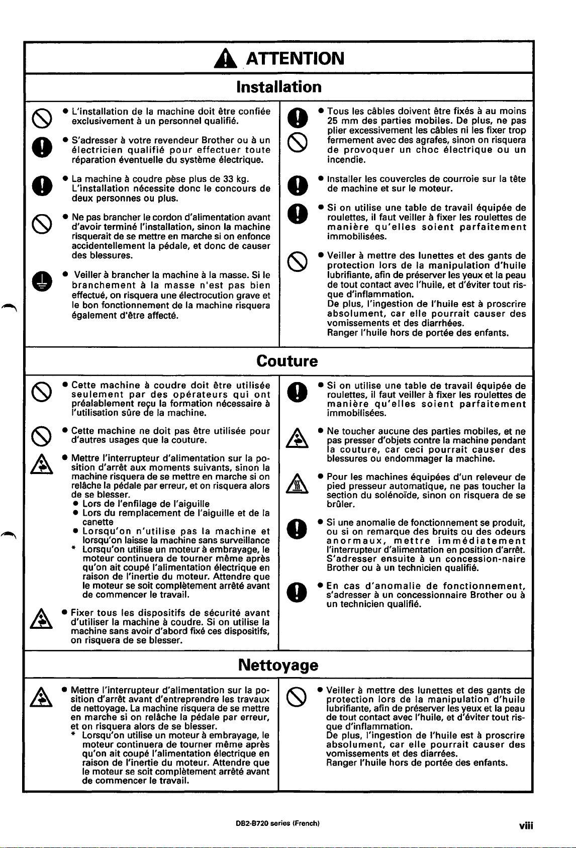
ATTENTION
Installation
""
~
• L'installation de
~
• S'adresser a votre revendeur Brother ou a un
•
•
•
•
~
• Veiller a brancher
•
• Cette
~
• Cette machine
~
• Mettre l'interrupteur d'alimentation sur
~
• Fixer
~
Ia
machine
a
un
exclusivement
electrician
reparation
La
machine a coudre pese plus de
L'installation
deux personnes
Ne
pas
d'avoir termine
risquerait de
accidentellement
des blessures.
branchement
effectue, on risquera une electrocution grave et
le bon fonctionnement de
egalement d'etre affecte.
qualifie
eventuelle du systeme electrique. incendie.
brancher le cordon d'alimentation avant roulettes, il taut veiller a fixer les roulettes de
se
personnel qualifie.
necessite done le concours de de machine et sur
ou
plus.
!'installation, sinon
mettre
Ia
pedale, et done de causer
Ia
machine a
a Ia
masse
doit
pour
effectuer
en
marche
n'est
Ia
machine risquera
etre confiee
toute
33
kg
Ia
machine
si
on enfonce
Ia
masse.
pas
.
Si
le lubrifiante, afin de preserver les yeux et
bien
Couture
machine a coudre
seulement
prealablement
!'utilisation
d'autres usages que
sition d'arret aux moments suivants, sinon
machine risquera
relache
de
se
blesser.
• Lors de l'enfilage de l'aiguille
•
Lors du remplacement de l'aiguille et
canette
•
Lorsqu'on
lorsqu'on laisse
* Lorsqu'on utilise
moteur continuera de tourner
qu'on ait coupe !'alimentation electrique
raison de l'inertie du moteur. Attendre que
le moteur
de commencer le travail.
tous
d'utiliser
machine sans avoir d'abord fixe
on risquera de
par
des
reJu
sOre e Ia
Ia
pedale par erreur, et
se
les
Ia
machine a coudre.
Ia
ne
doit
de
se
n'utilise
Ia
machine
un
soit completement arrete avant
dispositifs
se
blesser.
doit
etre
operateurs
formation necessaire a
machine.
pas etre utilisee pour
Ia
couture.
mettre
en
on
pas Ia
sans
moteur a embrayage, le
de securite avant
utilisee
qui
Ia
marche
risquera alors
machine
meme apres
Si
on utilise
ces
si
de
surveillance
dispositifs,
ont
po-
Ia
on
Ia
et
en
Ia
• Tous les cables doivent etre fixes a
•
~
• Installer les couvercles de courroie sur
•
• Si on utilise une table de travail equipee de
•
• Veiller a mettre des lunettes et des gants de
~
•
•
• Ne toucher aucune des parties mobiles, et
~
• Pour les machines equipees d'un releveur de
&
•
•
•
•
au
25
mm
plier excessivement les cables ni les fixer trop
fermement avec des agrafes, sinon on risquera
de
maniere
immobilisees.
protection
de tout contact avec l'huile, et d'eviter tout ris-
que d'inflammation.
De
absolument,
vomissements et des diarrheas.
Ranger l'huile hors de
Si
roulettes, il faut veiller a fixer les roulettes de
maniere
immobilisees.
pas
Ia
blessures ou endommager
pied presseur automatique, ne pas toucher
section du soleno'ide, sinon on risquera de
brOier.
Si
ou si
anormaux,
l'interrupteur
S'adresser
Brother
En
s'adresser
un technician qualifie.
des parties mobiles.
provoquer
plus, !'ingestion de
on utilise une table de travail equipee de
presser d'objets contre
couture,
une anomalie de fonctionnement
on
remarque des bruits ou des odeurs
ou a un
cas
d'anomalie
un
choc
le
moteur.
qu'elles
lors
car
qu'elles
car
d'alimentation
ensuite
soient
de Ia
elle
portae des enfants.
soient
ceci
mettre
a un
technician qualifie.
a un concessionnaire Brother
De
electrique
parfaitement
manipulation
l'huile
est a proscrire
pourrait
parfaitement
Ia
machine pendant
pourrait
Ia
machine.
immediatement
en
position d'arret.
concession-naira
de
fonctionnement,
moins
plus, ne pas
ou
un
Ia
tete
d'huile
Ia
peau
causer
causer
se
produit,
des
ne
des
Ia
se
ou
a
Nettoyage
• Mettre l'interrupteur d'alimentation sur
sition d'arret avant d'entreprendre les travaux
de nettoyage.
en
marche si on reiAche
et on risquera alors de
* Lorsqu'on utilise
moteur continuera de tourner
qu'on ait coupe I' alimentation electrique
raison de l'inertie du moteur. Attendre que
le moteur
de commencer le travail.
La
machine risquera de
se
soit completement arrete avant
Ia
pedale par erreur,
se
blesser.
un
moteur a embrayage, le
Ia
po-
se
mettre
meme apres
en
082-8720 series (french)
• Veiller a mettre des lunettes et des gants de
protection
lubrifiante, afin de preserver les yeux et
de tout contact avec l'huile, et d'eviter tout risque d'inflammation.
De
plus, !'ingestion de l'huile est a proscrire
absolument,
vomissements et des diarrees.
Ranger l'huile hors de
lors
car
de Ia
manipulation
elle
pourrait
portae des enfants.
d'huile
Ia
causer
peau
des
viii
Page 10
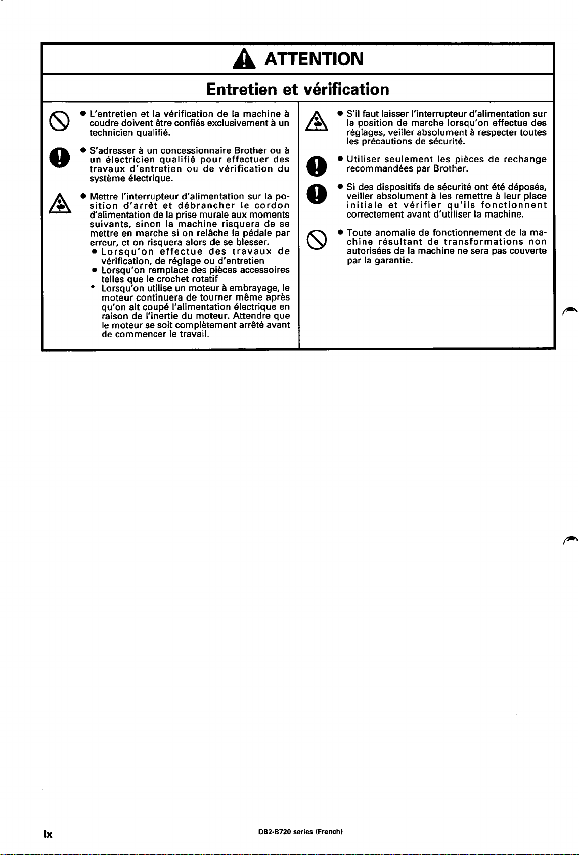
A
ATTENTION
(9
• L'entretien et
• S'adresser a
•
• Mettre l'interrupteur d'alimentation sur
~
Entretien
Ia
coudre doivent
technician
un
electrician
travaux
systeme
sition
d'alimentation de
suivants,
mettre
erreur, et on risquera
•
• Lorsqu'on remplace des pieces accessoires
* Lorsqu'on utilise un moteur a embrayage,
d'entretien
electrique.
d'arret
en
Lorsqu'on
verification, de
telles que le crochet rotatif
moteur continuera de tourner meme apres
qu'on ait coupe !'alimentation electrique
raison de l'inertie du moteur. Attendre que
le
moteur
de commencer
verification de
etre confies exclusivement a un
qualifie.
un
concessionnaire Brother ou a
qualifie
et
sinon
marche si on relache
Ia
Ia
effectue
reglage ou d'entretien
se
soit completement arrete avant
le travail.
pour
ou de
debrancher
prise murale aux moments
machine
alors de
Ia
machine a
effectuer
verification
le
risquera
Ia
pedale par
se
blesser.
des
travaux
des
du
Ia
po-
cordon
de se
de
et
verification
• S'il faut laisser l'interrupteur d'alimentation sur
~
•
•
•
•
(9
le
en
• Toute anomalie de fonctionnement de
Ia
position de marche lorsqu'on effectue des
reglages, veiller absolument
les precautions de securite.
Utiliser
recommandees par Brother.
Sides
veiller absolument a les remettre a leur place
initiale
correctement avant
chine
autorisees de
par
seulement
dispositifs de securite
et
verifier
resultant
Ia
garantie.
Ia
les pieces de rechange
d'utiliser
de
machine
a respecter toutes
ont
ete deposes,
qu'ils
transformations
fonctionnent
Ia
machine.
ne
sera pas couverte
Ia
rna-
non
ix
082-8720 series (French)
Page 11
Muchas gracias por haber adquirido una maquina de coser
las instrucciones de seguridad a continuaci6n y las explicaciones
BROTHER.
Antes de usar su nueva maquina, por favor lea
en
este manual.
AI usar maquinas de coser industriales,
aguja y de
partes.
antes de usar
Ia
palanca del tirahilos, y por consiguiente siempre existe peligro de
Siga las instrucciones para entrenamiento del personal y las instrucciones de seguridad y funcionamiento correcto
Ia
maquina de manera de usarla correctamente.
INSTRUCCIONES DE SEGURIDAD
[I] lndicaciones
Las indicaciones y simbolos usados
funcionamiento seguro de
se
indica a continuaci6n.
lndicaciones
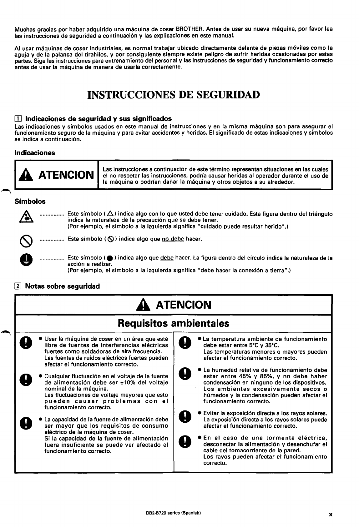
A ATENCION
Simbolos
de
seguridad y sus significados
Ia
maquina y para evitar accidentes y heridas.
Este slmbolo (
Ia
indica
(Por ejemplo,
naturaleza de
en
Las
instrucciones a continuaci6n de este termino representan situaciones
el
no respetar las instrucciones, podrla causar heridas
Ia
maquina o podrian dariar
~)
indica algo con lo que usted debe tener cuidado.
el
simbolo a
es
normal trabajar ubicado directamente delante de piezas m6viles como
este manual de instrucciones y
Ia
maquina y otros objetos a
Ia
precauci6n que
Ia
izquierda significa 11CUidado
se
debe tener.
en
El
sufrir
heridas ocasionadas
Ia
misma maquina son para asegurar
significado de estas indicaciones y simbolos
en
las cuales
al
operador durante el uso de
su
alrededor.
Esta
figura dentro del triangulo
puede resultar herido
11
.)
por
Ia
estas
el
[I]
0
0
0
Este slmbolo (
Este simbolo (
acci6n a realizar.
(Por ejemplo,
Notas
sobre seguridad
• Usar
• Cualquier fluctuaci6n
•
Ia
libre
fuertes como soldadoras de alta frecuencia.
Las
afectar
de
nominal de
Las
pueden
funcionamiento correcto.
La
ser
electrico de
Si
fuera
funcionamiento correcto.
maquina de coser
de fuentes de interferencias electricas
fuentes de ruidos electricos fuertes pueden
el
alimentaci6n
fluctuaciones de voltaje mayores que esto
capacidad de
mayor
Ia
capacidad de
insuficiente
<9)
indica algo que no debe hacer.
e ) indica algo
el
sfmbolo a
Requisitos ambientales
en
un
area que este
funcionamiento correcto.
en
el
debe ser ±10% del
Ia
maquina.
causar
Ia
fuente de alimentaci6n debe
que
los
Ia
maquina de coser.
Ia
se puede
voltaje de
problemas
requisitos
fuente de alimentaci6n
de
ver
que~
Ia
izquierda significa 11debe hacer
hacer.
La
figura dentro del circulo indica
A ATENCION
•
La
debe estar entre
Las
afectar
•
La
estar
condensaci6n
Los
humedos y
funcionamiento correcto.
• Evitar
La
afectar
• En el
desconectar
cable del tomacorriente de
Los rayos pueden afectar el funcionamiento
cor recto.
Ia
fuente
voltaje
con
el
consumo
afectado el
0
0
0
0
Ia
naturaleza de
Ia
conexi6n a tierra
temperatura ambiente de funcionamiento
temperaturas menores o mayores pueden
el
funcionamiento correcto.
humedad relativa de funcionamiento debe
entre
ambientes
Ia
exposici6n directa a los rayos solares.
exposici6n directa a los rayos solares puede
el
funcionamiento correcto.
caso
soc
y
35°C.
45% y 85%, y
en
ninguno de los dispositivos.
excesivamente
Ia
condensaci6n pueden afectar
de
una
Ia
alimentaci6n y desenchufar
11
.)
no
tormenta
Ia
pared.
debe
haber
secos
electrica,
o
el
el
Ia
082-8720 series (Spanish)
X
Page 12
•
~
•
0
•
0
• No conectar
~
• Asegurarse de realizar
•
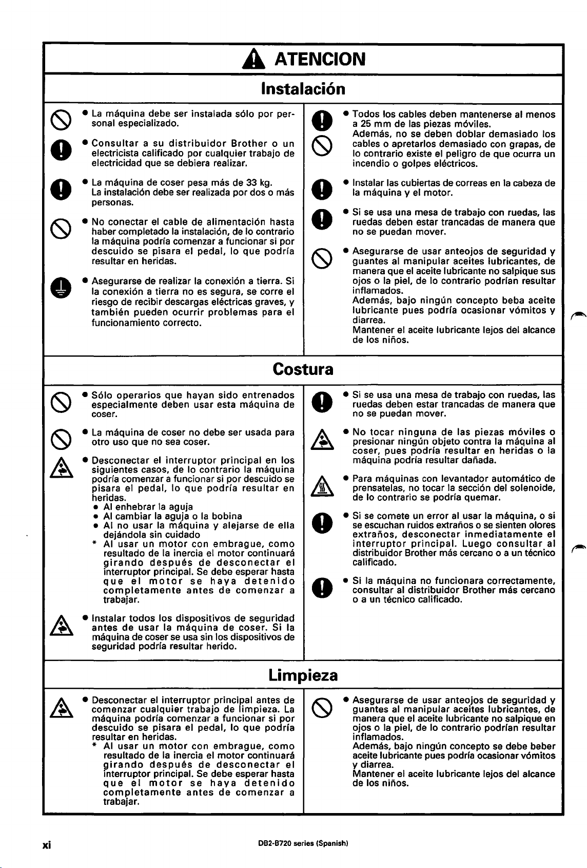
A ATENCION
lnstalaci6n
La
maquina debe ser instalada
sonal especializado.
Consultar
electricista calificado por cualquier trabajo de
electricidad que
La
maquina de coser pesa mas de
La
instalaci6n debe ser realizada por dos o mas
personas.
haber completado
Ia
maquina podrfa comenzar a funcionar si por
descuido
resultar
Ia
conexi6n a tierra no
riesgo de recibir descargas electricas graves, y
tambien
funcionamiento correcto.
a su
distribuidor
se
debiera realizar.
el
cable de alimentaci6n hasta
Ia
instalaci6n, de lo contra rio
se
pisara el pedal, lo
en
heridas.
pueden
ocurrir
Ia
es
s61o
por
per-
Brother
conexi6n a tierra. Si
segura,
problemas
33
que
se
o un
kg.
podrfa
corre
para el
el
• Todos los cables deben mantenerse
0
~
• lnstalar las cubiertas de correas
0
• Si
0
• Asegurarse de usar anteojos de seguridad y
~
al
a
25
mm
Ademas, no se deben
cables o apretarlos demasiado con grapas, de
lo contrario existe
incendio o golpes electricos.
Ia
maquina y
ruedas deben estar trancadas de manera que
no
guantes al manipular aceites lubricantes, de
manera que
ojos o
inflamados.
Ademas, bajo
lubricante pues podrfa ocasionar
diarrea.
Mantener
de los n i
de las piezas m6viles.
el
motor.
se
usa una mesa de trabajo con ruedas, las
se
puedan mover.
el
Ia
aceite lubricante no salpique sus
piel, de lo contrario podrfan resultar
ningun
el
aceite lubricante lejos del alcance
nos.
doblar
el
peligro de que ocurra un
concepto beba aceite
demasiado los
en
menos
Ia
cabeza
v6mitos
de
y
("
• Solo
•
• Desconectar
• lnstalar
operarios
especialmente deben usar esta maquina de
coser.
La
maquina de coser no debe ser usada para
otro uso que no
siguientes casos, de lo contrario
podrfa comenzar a funcionar
pisara el
heridas.
•
AI
enhebrar
•
AI
cambiar
• AI no usar
dejandola sin cuidado
* AI
usar
resultado de
girando
interrupter principal.
que
el
completamente
trabajar.
antes
maquina de coser
seguridad podrfa resultar herido.
todos
de
que hayan sido entrenados
sea
coser.
el
interrupter
pedal,
usar
lo
que
Ia
aguja
Ia
aguja o
Ia
maquina
un
motor
Ia
inercia
despues
motor
antes
los dispositivos de seguridad
Ia
maquina
se
usa
principal
Ia
si
por descuido
podrfa
Ia
con
el
de
Se
debe esperar hasta
se
haya
sin los dispositivos de
resultar
bobina
y alejarse de ella
embrague,
motor
desconectar
detenido
de
comenzar
de coser. Si
en los
maquina
como
continuara
Costura
0
se
en
0
el
a
0
Ia
• Si
se
usa
ruedas deben estar trancadas de manera que
no
• No
presionar ningun objeto contra
coser, pues
maquina podrfa resultar danada.
•
Para
prensatelas, no tocar
de lo contrario
•
Si
se
se
escuchan ruidos extranos o
extranos,
interrupter
distribuidor Brother
calificado.
• Si
consultar
o a un tecnico calificado.
una mesa de trabajo con ruedas, las
se
puedan mover.
tocar
ninguna
maquinas con levantador automatico de
comete un error
desconectar
Ia
maquina no funcionara correctamente,
al
distribuidor Brother mas cercano
de
las piezas
podrla
principal.
resultar en heridas o
Ia
se
secci6n del solenoide,
podrfa quemar.
al
usar
Ia
se
inmediatamente
Luego
mas cercano o a un tecnico
m6viles
Ia
maquina
maquina, o si
sienten olores
consultar
o
al
Ia
el
al
Limpieza
• Desconectar el
comenzar
maquina podrfa comenzar a funcionar si
descuido se pisara el pedal,
resultar
* AI
en
usar
resultado de
girando
interrupter principal.
que
completamente
trabajar.
xi
cualquier
heridas.
un
despues
el
motor
interrupter
motor
Ia
inercia
principal antes de
trabajo de limpieza.
con
embrague,
el
motor
de
desconectar
Se
debe esperar hasta
se
haya
antes
de
La
lo
que
continuara
detenido
comenzar
por
podrfa
como
082·8720 series (Spanish)
el
a
• Asegurarse de usar anteojos de seguridad y
guantes al manipular aceites lubricantes, de
manera que
ojos o
inflamados.
Ademas, bajo ningun concepto
aceite lubricante pues podrfa ocasionar v6mitos
y diarrea.
Mantener
de los ninos.
el
Ia
aceite lubricante no salpique
piel, de lo contrario podrfan resultar
se
debe beber
el
aceite lubricante lejos del alcance
en
Page 13
0
A ATENCION
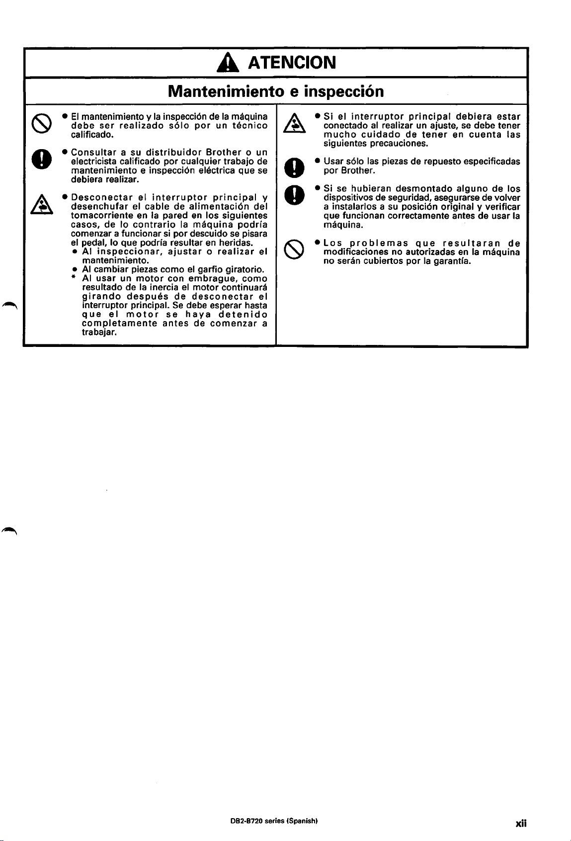
Mantenimiento e inspeccion
•
El
mantenimiento y
debe
ser
calificado.
•
Consultar
electricista calificado por cualquier trabajo de
mantenimiento e inspecci6n electrica que
debiera realizar.
•
Desconectar
desenchufar
tomacorriente
casos, de lo
comenzar a funcionar
el pedal, lo que podrfa resultar
• AI
mantenimiento.
•
AI
realizado
a su
inspeccionar,
cambiar piezas como
* AI usar un
resultado de
girando
interruptor principal.
que
el
completamente
trabajar.
Ia
inspecci6n de
distribuidor
el
interruptor
el cable de
en
Ia
pared
contrario
despues
motor
motor
Ia
inercia
si
se
antes
Ia
s61o
por
alimentaci6n
en
Ia
maquina
por descuido
ajustar o realizar
el
con
garfio giratorio.
embrague,
el
motor
de
desconectar
Se
debe esperar hasta
haya
de
maquina
un
tecnico
Brother
principal
los siguientes
en
podrfa
se
pisara
heridas.
como
continuara
detenido
comenzar
o un
se
del
el
el
• Si el
• Usar
0
y
0
a
• Si se hubieran
•
interruptor
conectado
mucho
siguientes precauciones.
por Brother.
dispositivos de seguridad, asegurarse de volver
a instalarlos a
que funcionan correctamente antes de usar
maquina.
Los
modificaciones no autorizadas
no
seran cubiertos por
al
cuidado
s61o
las piezas de repuesto especificadas
problemas
principal
realizar
un
de
tener
desmontado
su
posici6n original y verificar
que
Ia
debiera
ajuste,
en
alguno
resultaran
en
garantra.
se
debe tener
cuenta
Ia
estar
las
de los
Ia
de
maquina
082-8720 series (Spanish)
xii
Page 14
[11
Warning labels
[11
Warnschilder
III
Etiquettes
III
Etiquetas de advertencia
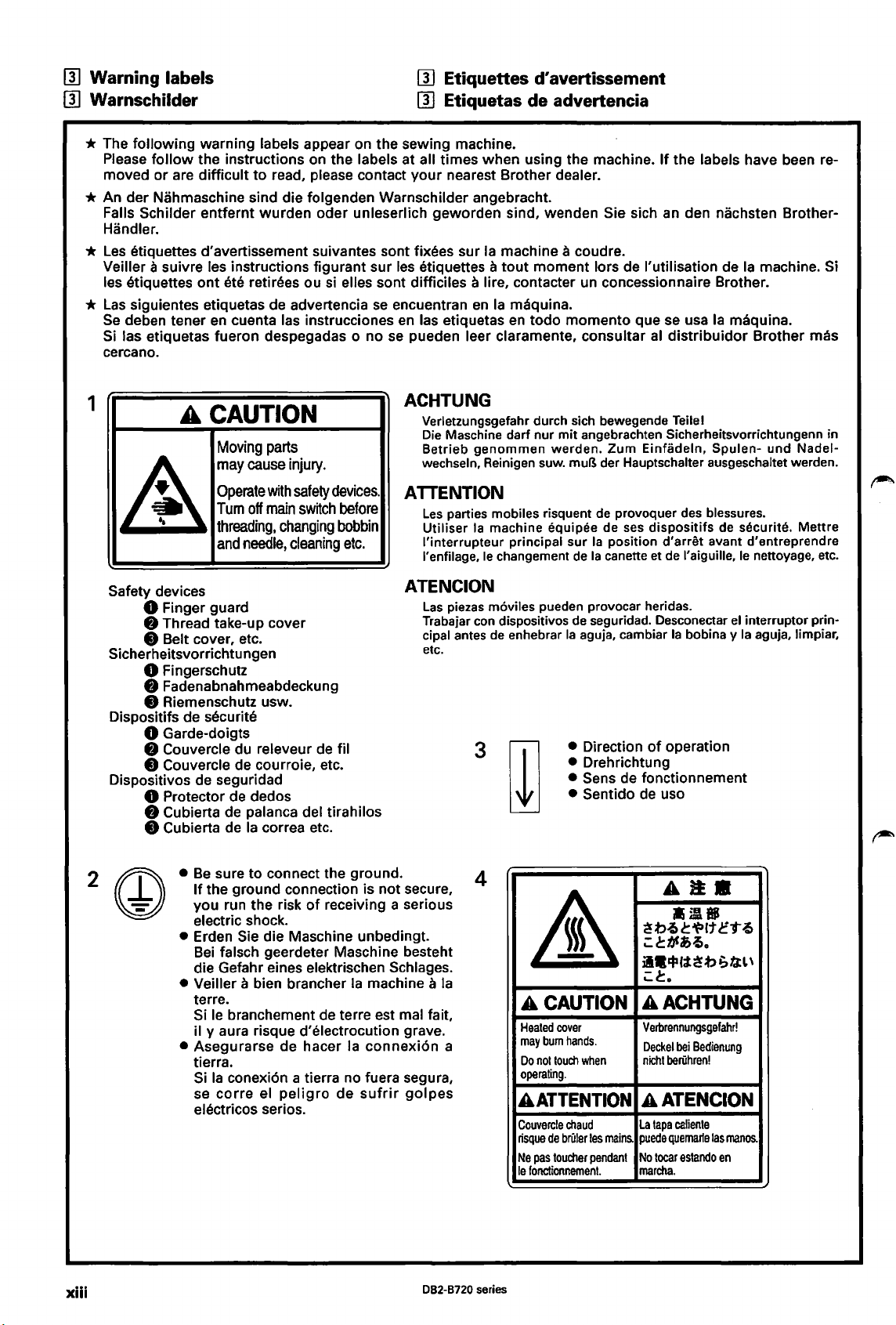
* The following warning labels appear on the sewing machine.
Please
moved or are difficult to read, please contact
follow
the instructions on the labels at all times when using the machine.
your
nearest Brother dealer.
* An der Nahmaschine sind die folgenden Warnschilder angebracht.
Falls
Schilder entfernt wurden oder unleserlich geworden sind, wenden Sie sich an den nachsten Brother-
Handler.
*
les
etiquettes d'avertissement suivantes sont fixees sur
Veiller
les etiquettes
*
las
Se
Si las etiquetas fueron despegadas o no
cercano.
a suivre les instructions figurant sur
ont
ete retirees ou si elles sont difficiles a lire, contacter un concessionnaire Brother.
siguientes etiquetas de advertencia
deben tener
en
cuenta las instrucciones
se
les
etiquettes a tout moment Iars de !'utilisation de
encuentran
en
las etiquetas
se
pueden leer claramente, consultar
en
Ia
Ia
d'
avertissement
machine a coudre.
maquina.
en
todo momenta que
If
the labels have been re-
Ia
machine. Si
se
usa
Ia
maquina.
al
distribuidor
Brother mas
1
A
CAUTION
Moving
may
Operate
Tum
A
threading,
and
Safety devices
8 Finger guard
8 Thread take-up cover
8 Belt cover, etc.
Sicherheitsvorrichtungen
8 Fingerschutz
8 Fadenabnahmeabdeckung
8 Riemenschutz usw.
Dispositifs de
securite
8 Garde-doigts
8 Couvercle du releveur de fil
8 Couvercle de courroie, etc.
Dispositivos de seguridad
8 Protector de dedos
8 Cubierta de palanca del tirahilos
8 Cubierta de
parts
cause
with
off
main
changing
needle,
Ia
correa etc.
injury.
safety
devices.
switch
cleaning
before
bobbin
etc.
ACHTUNG
Verletzungsgefahr durch sich bewegende Teilel
Die Maschine darf nur mit angebrachten Sicherheitsvorrichtungenn in
Betrieb
wechseln, Reinig
genommen
en
werden.
suw. muB der Hauptschalter ausgeschaltet werden.
Zum
Einfadeln, Spulen-
und
ATTENTION
Les
parties mobiles risquent de provoquer des blessures.
Utiliser
l'interrupteur
l'enfilage,
Ia
machine equipee de ses
principal sur
le
changement
de
Ia
Ia
dispositifs
position
canette et
d'arret
de
l'aiguille,
de securite. Mettre
avant d'entreprendre
le
nettoyage, etc.
ATENCION
Las
piezas m6viles pueden provocar heridas.
Trabajar con dispositivos
cipal antes
etc.
de
enhebrar
3
de
seguridad. Desconectar
Ia
aguja, cambiar
• Direction
• Drehrichtung
• Sens de fonctionnement
• Sentido de uso
Ia
of
operation
el
bobina y
interrupter prin-
Ia
aguja, limpiar,
Nadel-
•
Be
xiii
sure to connect the ground.
If
the ground connection is not secure,
of
you run the risk
electric shock.
• Erden Sie die Maschine unbedingt.
Bei
falsch geerdeter Maschine besteht
die Gefahr eines elektrischen
Veiller a bien brancher
•
terre.
Si le branchement de terre est mal fait,
il y aura risque d'electrocution grave.
• Asegurarse de hacer
tierra.
Si
Ia
conexi6n a tierra no fuera segura,
corre
se
electricos serios.
el
receiving a serious
Ia
Ia
peligro
de
Schlages.
machine a
connexi6n a
sufrir
golpes
082-8720 series
Ia
4
A CAUTION
Heated
may
Do
operating.
A
Couvercle
risque
Ne
le
&
cover
bum
hands.
not
touch
ATTENTION
chaud
de
briller
pas
toucher
fonctionnement.
when
les
mains.
pendant
AJ!.
.;A.
~t>l»ct~lt~'tl»
;:
c!::bfl>{).
il·~~~~t>GfctL\
;:
c!::.
AACHTUNG
Verbrennungsgefahr!
Deckel
bei
beriihren!
tapa
caliente
quemarle
tocar
Bedienung
las
estando
manos.
en
nicht
AATENCION
La
puede
No
marcha.
Page 15
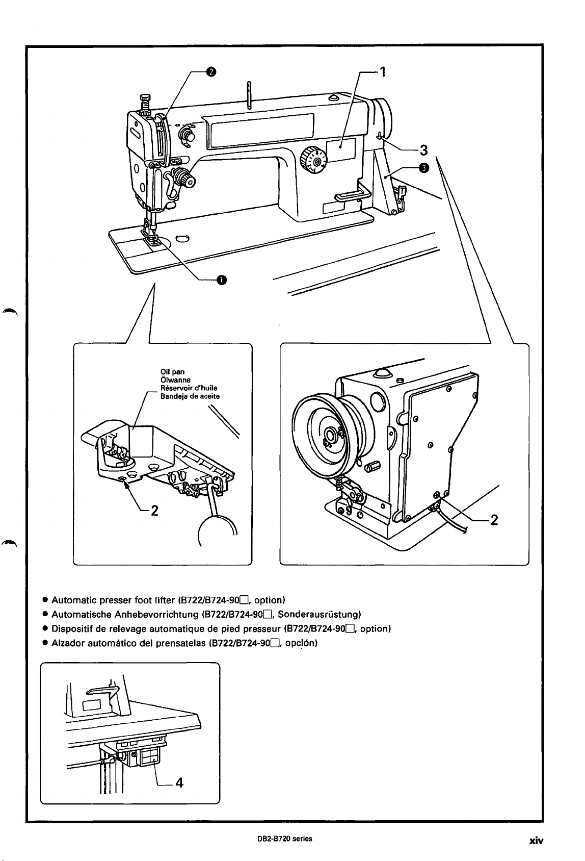
Oil
pan
Olwanne
Reservoir d'huile
8andeja de
aceite
• Automatic presser foot lifter (8722/8724-900, option)
• Automatische Anhebevorrichtung (8722/8724-900, Sonderausrustung)
• Dispositif de relevage automatique de pied presseur (8722/8724-900, option)
• Alzador automatico del prensatelas (8722/8724-900,
opc_i6n)
082-8720 series
xiv
Page 16
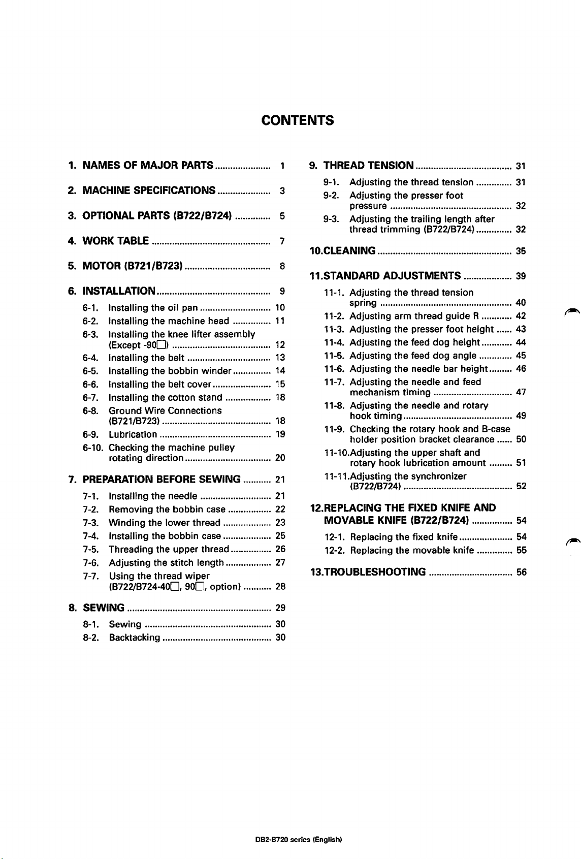
CONTENTS
1.
NAMES
2. MACHINE SPECIFICATIONS..................... 3
3. OPTIONAL PARTS (B722/B724) .............. 5
4. WORK TABLE ............................................... 7
5.
MOTOR (B721/B723) .................................. 8
6. INSTALLATION ............................................. 9
6-1.
6-2.
6-3.
6-4.
6-5.
6-6.
6-7.
6-8.
6-9.
6-10. Checking the machine pulley
7. PREPARATION
7-1. Installing the needle ............................
7-2. Removing the bobbin
7-3. Winding the lower thread ...................
7-4.
7-5.
7-6.
7-7.
OF
MAJOR
Installing the oil pan ............................
Installing the machine head ...............
Installing the knee lifter assembly
(Except
Installing the belt .................................
Installing the bobbin winder ...............
Installing the belt cover .......................
Installing the cotton stand ..................
Ground Wire Connections
(8721/8723) ...........................................
Lubrication ............................................
rotating direction ..................................
Installing the bobbin
Threading the upper thread ................
Adjusting the stitch length ..................
Using the thread
(8722/8724-400,
-900)
PARTS ..................... .
..
.......................... ......
BEFORE
SEWING ...........
case
case
wiper
900,
option) ...........
.....
.................
...................
10
11
12
13
14
15
18
18
19
20
21
21
22
23
25
26
27
28
9.
THREAD TENSION ......................................
9-1.
Adjusting the thread tension ..............
9-2.
Adjusting the presser
pressure ................................................
9-3.
Adjusting the trailing length after
thread trimming (8722/8724) ..............
foot
10.CLEANING .....................................................
11.STANDARD ADJUSTMENTS ...................
11-1. Adjusting the thread tension
spring ....................................................
11-2. Adjusting arm thread
11-3. Adjusting the presser
11-4. Adjusting the feed dog height ............ 44
11-5.
Adjusting the feed dog angle .............
11-6. Adjusting the needle bar height .........
11-7.
Adjusting the needle and feed
mechanism timing ...............................
11-8.
Adjusting the needle and rotary
hook timing ...........................................
11-9. Checking the rotary hook and 8-case
holder position bracket clearance ......
11-10.Adjusting the upper shaft and
rotary hook lubrication amount .........
11-11.Adjusting the synchronizer
(8722/8724) ...........................................
12.REPLACING THE FIXED KNIFE
guideR
foot
height ......
AND
............
MOVABLE KNIFE (B722/B724) ................
12-1.
Replacing the fixed knife .....................
12-2.
Replacing the movable knife ..............
13.TROUBLESHOOTING .................................
31
31
32
32
35
39
40
42
43
45
46
47
49
50
51
52
54
54
55
56
8.
SEWING .........................................................
8-1. Sewing ..................................................
8-2. 8acktacking ...........................................
29
30
30
082-8720 series (English)
Page 17
IN
HALT
1. HAUPTTEILE ................................................ .
TECHNISCHE DATEN ................................. 3
2.
3. SONDERZU8EH0RTEILE
(8722/8724) ............................................ :..... 5
4. NAHTISCH ........
5.
MOTOR (8721/8723) .................................. 8
.....
........................................ 7
6. MONTAGE..................................................... 9
6-1.
Montage der Olwanne .........................
6-2.
Montage des Maschinenoberteils ......
6-3.
Montage der Kniehebel
(auBer
6-4.
Riemenmontage ...................................
6-5.
Montage des Spulers ...........................
6-6.
Montage des Riemenschutzes ............
6-7.
Montage des Spulentragers ................
6-8.
AnschluB des Erdungskabels
(8721/8723) ...........................................
6-9.
Schmierung ..........................................
6-10.
Kontrolle der Nahmaschinen-
Riemenscheibendrehrichtung .............
7. VOR8EREITUNGEN
7-1. Einsetzen der Nadel .............................
7-2. Herausnehmen der Spulenkapsel ......
7-3.
Aufwickeln des Unterfadens ...............
7-4.
Einsetzen der Spulenkapsel ................
7-5.
Einfadeln des Oberfadens ...................
7-6.
Einstellen der Stich lange .....................
7-7.
Verwendung des Fadenwischers
(8722/8724-400,
Sonderausrustung) ..............................
-900)
.........................................
ZUM
NAHEN ..........
900,
8. HAHEN ...........................................................
8-1.
Hahen ....................................................
8-2.
Verriegeln ..............................................
10
11
12
13
14
15
18
18
19
20
21
21
22
23
25
26
27
28
29
30
30
9. FADENSPANNUNG .....................................
9-1.
Einstellen der Fadenspannung ...........
9-2.
Einstellen des StoffdruckerfuB-
drucks ....................................................
9-3.
Einstellen der verbleibenden
Fadenlange nach dem
Fadenabschneiden (8722/8724) ..........
10.REINIGUNG ...................................................
11.STANDARDEINSTELLUNGEN ..................
11-1.
Einstellen der Fadenspannungs-
feder ......................................................
11-2.
Einstellen der Armfadenfuhrung R ....
11-3.
Einstellen der StoffdruckerfuBhohe ...
11-4.
Einstellen der Transporteurhohe ........ 44
11-5.
Einstellen der Transprteurneigung ..... 45
11-6.
Einstellen der Nadelstangenhohe ...... 46
11-7.
Einstellen der Nadel- und
Transporteursynchronisation ..............
11-8. Einstellen der Nadei-
Greifersynchronisierung ......................
11-9.
Prufung des Abstands zwischen
Greifer und Spulenkapsel-
positionshalterung ...............................
11-10.Einstellen der Schmierung der
oberen Welle und des Drehgreifers ...
11-11.Einstellen des Synchronisators
(8722/8724) ...........................................
12.ERSETZEN DES FESTSTEHENDEN UNO
DES 8EWEGLICHEN MESSERS
(8722/8724) .................................................. 54
12-1. Ersetzen des feststehenden
Messers .................................................
12-2.
Ersetzen des beweglichen
Messers .................................................
13.FEHLERSUCHE .............................................
31
31
32
32
35
39
40
42
43
47
49
50
51
52
54
55
60
082-8720 series (German)
Page 18
1.
NOM
DES PIECES PRINCIPALES ........... .
SPECIFICATIONS
2.
3.
4.
PIECES
TABLE
EN OPTION (8722/8724) ............ 5
DE
TABLE DES MATIERES
DE
LA
MACHINE........ 3
TRAVAIL .................................... 7
9. TENSION DU FIL .........................................
9-1.
Reglage de
9-2.
Reglage de
presseur ................................................
9-3.
Reglage de
residue! apres
(8722/8724) ...........................................
Ia
tension du fil ................
Ia
pression du pied
Ia
longueur de fil
Ia
coupe des fils
33
33
34
34
5. MOTEUR (8721/8723) ............................... 8
6. INSTALLATION............................................. 9
6-1.
Installation du reservoir d'huile .........
6-2.
Installation de
6-3.
Installation de !'ensemble de
releveur
6-4.
Installation de
6-5.
Installation du bobineur de canette
6-6.
Installation du couvercle de
courroie .................................................
6-7.
Installation de
bobine ...................................................
6-8.
Raccord du cable de mise a
(8721/8723) ...........................................
6-9.
Lubrification ..........................................
6-10.
Verification du sens de rotation de
Ia
poulie de machine ...........................
7. PREPARATIFS AVANT
7-1.
Installation de J'aiguille .......................
7-2.
Retrait de
7-3. 8obinage du fil inferieur .....................
7-4.
Installation de
7-5.
Enfilage du fil superieur ......................
7-6.
Reglage de
7-7. Utilisation du tire-fils
(8722/8724-400,
Ia
tete de machine ......
au
genou (Sauf
Ia
courroie ...................
Ia
broche porte-
Ia
boite a canette ................
Ia
boite a canette ........
Ia
longueur de point ........
900,
-900)
LA
COUTURE
option) ...........
Ia
terre
8. COUTURE ......................................................
8-1.
Couture ..................................................
8-2.
Point d'arret ..........................................
..........
...
.....
10
11
12
13
14
15
18
18
19
20
21
21
22
24
25
26
27
28
29
30
30
10.NETTOVAGE .................................................
11.REGLAGES STANDARD ............................
11-1.
Reglage du ressort de tension du
fil ............................................................
11-2.
Reglage du guide-fil D du bras ..........
11-3.
Reglage de
presseur ................................................
11-4.
Reglage de
d'entrainement .....................................
11-5. Reglage de J'angle de
d'
entrainement .....
11-6.
Reglage de
aiguille ...................................................
11-7.
Reglage de
l'aiguille et du dispositif
d'
entrainement .....................................
11-8.
Reglage de
l'aiguille et du crochet rotatif .............
11-9.
Verification de l'ecart entre
crochet rotatif et le support de
position de boite
11-10.Reglage de
lubrification de l'arbre superieur
et du crochet rotatif .............................
11-11.Reglage du synchroniseur
(8722/8724) ...........................................
Ia
hauteur du pied
Ia
hauteur de
..
Ia
hauteur de
Ia
synchronisation de
Ia
synchronisation de
Ia
Ia
griffe
..............................
Ia
a canette .................
Ia
quantite de
griffe
barre a
le
12.REMPLACEMENT DU COUTEAU FIXE
ET DU COUTEAU MOBILE
(8722/8724) ..................................................
12-1.
Rem
placement du couteau fixe ..........
12-2.
Remplacement du couteau mobile ....
13.RESOLUTION DES PROBLEMES ............
35
39
40
42
43
44
45
46
48
49
50
51
53
54
54
55
64
082·8720 series {French)
Page 19
CONTENIDO
1.
NOM8RES
2. ESPECIFICACIONES
MAQUINA
3.
PARTES
4.
MESA
DE
PIEZAS PRINCIPALES
DE
LA
....
..................................................... 3
OPCIONALES (8722/8724) ....... 5
DE
TRA8AJO ................................... 7
5. MOTOR (8721/8723) .................................. 8
6. INSTALACION .............................................. 9
6-1.
lnstalaci6n de
6-2.
lnstalaci6n de
maquina ................................................
6-3.
lnstalacion del conjunto del
levantador de
(Excepto
6-4.
lnstalacion de
6-5.
lnstalaci6n de
6-6.
lnstalacion de
correa ....................................................
6-7.
lnstalacion del soporte del carrete .....
6-8.
Conexion del cable a tierra
(8721/8723) ...........................................
6-9.
Lubricacion ...........................................
6-10. Verificaci6n de
rotaci6n de
7. PREPARATIVOS ANTES
7-1. Colocacion de
7-2. Maners de sacar
bobina ...................................................
7-3.
8obinado del hilo inferior ...................
7-4.
lnstalaci6n de
7-5.
Enhebrado del hilo superior ...............
7-6.
Ajuste del largo de puntada ...............
7-7.
Uso del retirador de hilo
(8722/8724-400,
-900)
Ia
Ia
bandeja de aceite ....
Ia
cabeza de
rodilla
......
..
.............................
Ia
correa .......................
Ia
bobinadora ..............
Ia
cubierta de
Ia
direccion de
polea de
Ia
aguja ........................
Ia
caja de
Ia
caja de
900,
Ia
Ia
Ia
maquina
DE
COSER .......
Ia
Ia
bobina
opci6n) ...........
...
....
10
11
12
13
14
15
18
18
19
20
21
21
22
24
25
26
27
28
9. TENSION
9-1.
9-2.
9-3.
DEL
HILO ....................................
Ajuste de
Ajuste de
prensatelas ............................................
Ajuste del largo fibre de hilo
despues de cortar
(8722/8724) ...........................................
Ia
tension del hilo ...............
Ia
presion del
el
hilo
10.LIMPIEZA .......................................................
11.AJUSTES ESTANDARES ...........................
11-1.
Ajuste del resorte del tirahilos ...........
11-2.
Ajuste del guiahilos R del brazo ........
11-3.
Ajuste de
11-4.
Ajuste de
11-5.
Ajuste del angulo del alimentador .....
11-6.
Ajuste de
aguja ...................................................... 46
11-7.
Ajuste de
aguja y
alimentaci6n .........................................
11-8.
Ajuste de sincronizaci6n de
y del garfio giratorio ............................ 49
1-9.
Verificaci6n de
1
del garfio giratorio
del soporte de
11-10.Ajuste de
superior
1 1-11.Ajuste del sincronizador
(8722/8724) ...........................................
12.CAM810
Y CUCHILLA
12-1.
Cambio de
12-2.
Cambiar
13.LOCALIZACION
Ia
altura del prensatelas ....
Ia
altura del alimentador
Ia
altura de
Ia
sincronizacion de
el
mecanismo de
Ia
separaci6n entre
y
Ia
Ia
caja 8 ......................
Ia
lubricaci6n del eje
y
el
garfio giratorio ..............
DE
LA
CUCHILLA FIJA
MOVIL
Ia
(8722/8724) ...........
Ia
cuchilla fija ....................
cuchilla m6vil ...................
DE
AVERIAS ...................
Ia
barra de
mensula
Ia
Ia
aguja
...
33
33
34
34
35
39
40
42
43
44
45
48
50
51
53
54
54
55
68
8. COSTURA ......................................................
8-1. Costura ..................................................
8-2. Rematado ..............................................
29
30
30
082·8720 series (Spanish)
Page 20
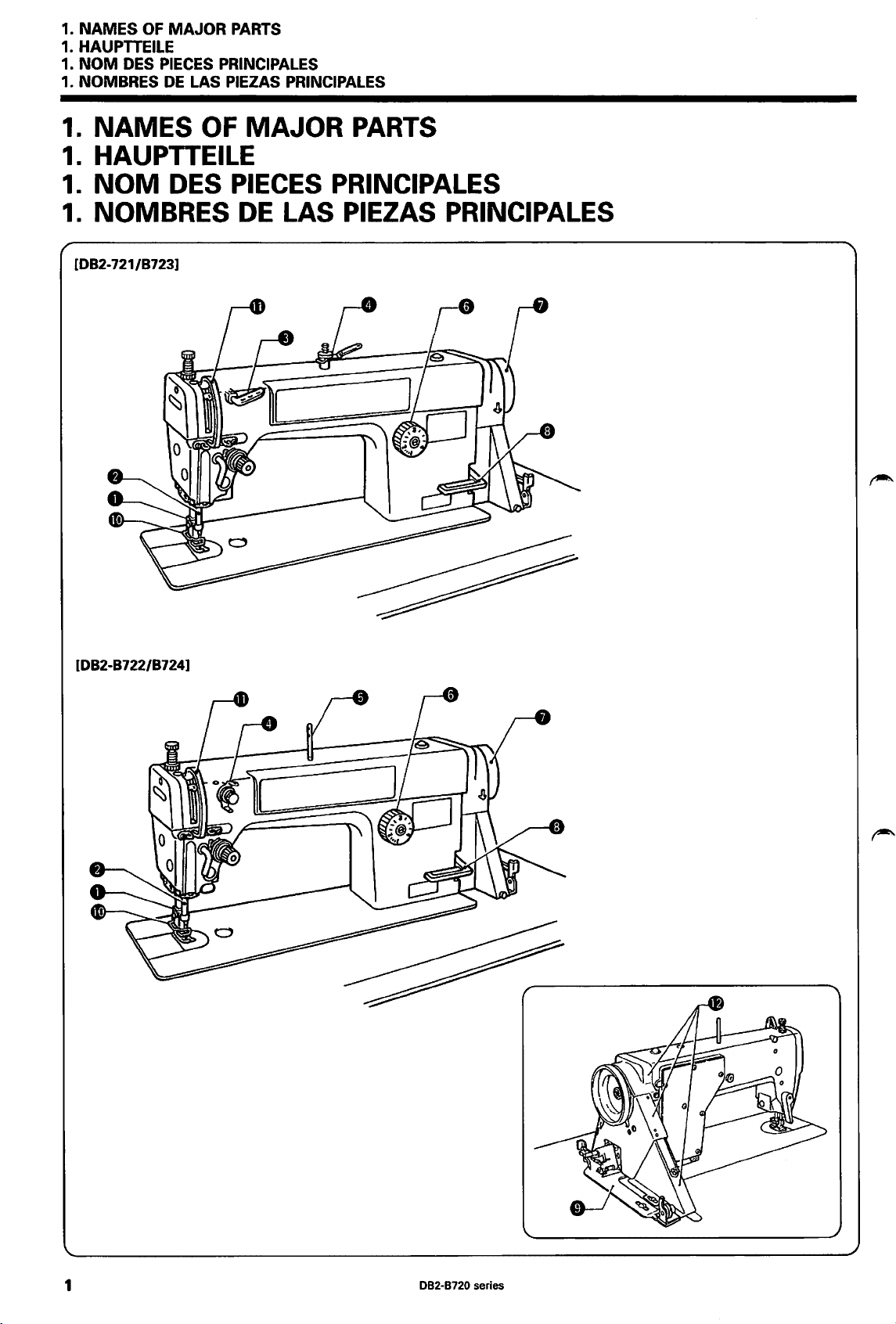
1.
NAMES
1.
HAUPTTEILE
1.
NOM
1. NOMBRES
1.
NAMES
1.
HAUPTTEILE
1.
NOM
1.
NOMBRES
[082-721/8723]
OF
MAJOR
DES PIECES PRINCIPALES
DE
DES
PARTS
LAS PIEZAS PRINCIPALES
OF
MAJOR
PIECES
DE
LAS PIEZAS PRINCIPALES
PARTS
PRINCIPALES
[082-8722/8724]
1
082-8720 series
Page 21
1.
NAMES
1.
HAUPTTEILE
1.
NOM
DES
1.
NOMBRES
OF
MAJOR
PIECES
DE
PARTS
PRINCIPALES
LAS
PIEZAS
PRINCIPALES
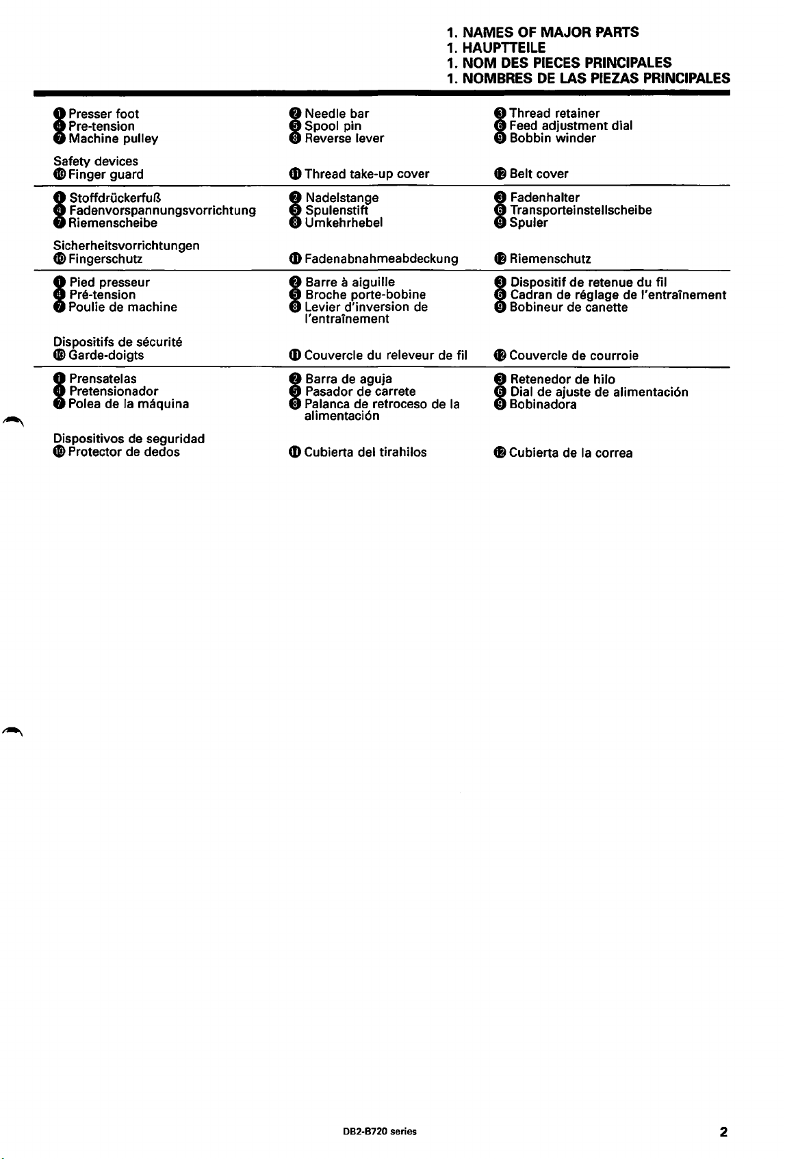
Presser foot
Pre-tension
Machine
I
Safety devices
0 Finger guard
StoffdruckerfuB
Fadenvorspannungsvorrichtung
Riemenscheibe
I
Sicherheitsvorrichtungen
tD
Fingerschutz
Pied presseur
Pre-tension
Poulie de machine
I
Dispositifs de
G>
Garde-doigts
Prensatelas
Pretensionador
Polea de
I
Dispositivos de seguridad
(!) Protector de dedos
pulley
securite
Ia
maquina
Needle bar
Spool pin
Reverse lever
I
CD
Thread take-up cover
Nadelstange
Spulenstift
Umkehrhebel
I
CD
Fadenabnahmeabdeckung
Barre a aiguille
Broche porte-bobine
Levier d'inversion
I
I' entrainement
CD
Couvercle du releveur de fil
Barra de aguja
Pasador de carrete
Palanca de retroceso de
I
alimentaci6n
CD
Cubierta del tirahilos
de
Ia
Thread retainer
Feed
adjustment dial
Bobbin winder
I
fB
Belt cover
Fadenhalter
Tra
nsportei nstellschei
Spuler
I
fB
Riemenschutz
Dispositif de retenue du fil
Cadran de reglage de l'entrainement
Bobineur de canette
I
fB
Couvercle de courroie
Retenedor de hilo
Dial de ajuste de alimentaci6n
Bobinadora
I
8 Cubierta de
Ia
correa
be
082-8720 series
2
Page 22
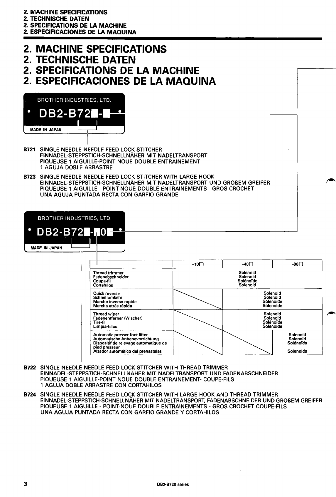
2. MACHINE SPECIFICATIONS
2. TECHNISCHE DATEN
SPECIFICATIONS
2.
2. ESPECIFICACIONES
2.
MACHINE SPECIFICATIONS
2.
TECHNISCHE DATEN
2.
SPECIFICATIONS
2.
ESPECIFICACIONES
8721
SINGLE
EINNADEL-STEPPSTICH-SCHNELLNAHER
PIQUEUSE
1 AGUJA
8723
SINGLE
EINNADEL-STEPPSTICH-SCHNELLNAHER
PIQUEUSE
UNA AGUJA PUNTADA
NEEDLE
NEEDLE NEEDLE
DE
LA
MACHINE
DE
LA
NEEDLE
1 AIGUILLE-POINT
DOBLE
ARRASTRE
1 AIGUILLE -
POINT-NOUE
RECTA
MAQUINA
DE
FEED
LOCK
NOUE
FEED
LOCK
CON
LA
DE
STITCHER
DOUBLE
STITCHER
DOUBLE
GARFIO
MACHINE
LA
MAQUINA
MIT
NADELTRANSPORT
ENTRAINEMENT
WITH
MIT
NADELTRANSPORT
ENTRAINEMENTS-
GRANDE
LARGE
HOOK
UNO
GROBEM
GROS
GREIFER
CROCHET
Thread
trimmer
Fadenabschneider
Coupe-fil
Cortahilos
Quick reverse
Schnellumkehr
Marche inverse rapide
Marcha
Thread wiper
Fadenentferner (Wischer)
Tire-fil
Limpia-hilos
Automatic presser
Automatische Anhebevorrichtung
Dispositif de
pied presseur
Alzador automatico del prensatelas
8722
SINGLE
EINNADEL-STEPPSTICH-SCHNELLNAHER
PIQUEUSE
1 AGUJA
8724
SINGLE
EINNADEL-STEPPSTICH-SCHNELLNAHER
PIQUEUSE
UNA AGUJA PUNTADA
NEEDLE
DOBLE
NEEDLE
NEEDLE
1 AIGUILLE-POINT
ARRASTRE
NEEDLE
1 AIGUILLE-
FEED
FEED
POINT-NOUE
RECTA
atras rapida
foot
lifter
relevage automatique de
LOCK
STITCHER
NOUE
CON
DOUBLE
CORTAHILOS
LOCK
STITCHER
DOUBLE
CON
GARFIO
WITH
MIT
NADELTRANSPORT
ENTRAINEMENT-
MIT
NADEL
ENTRAINEMENTS-
GRANDE Y CORTAHILOS
THREAD
WITH
LARGE
TRANSPORT,
Solenoid
Solenoid
Soleno·ide
Solenoid
TRIMMER
UNO
FADENABSCHNEIDER
COUPE-FILS
HOOK
AND
THREAD
FADENABSCHNEIDER
GROS
CROCHET
Solenoid
Solenoid
Soh!noide
Solenoide
Solenoid
Solenoid
Solenoide
Solenoide
TRIMMER
UNO
GROBEM
COUPE-FILS
Solenoid
Solenoid
Solenoide
Solenoide
GREIFER
3
DB2-B720 series
Page 23
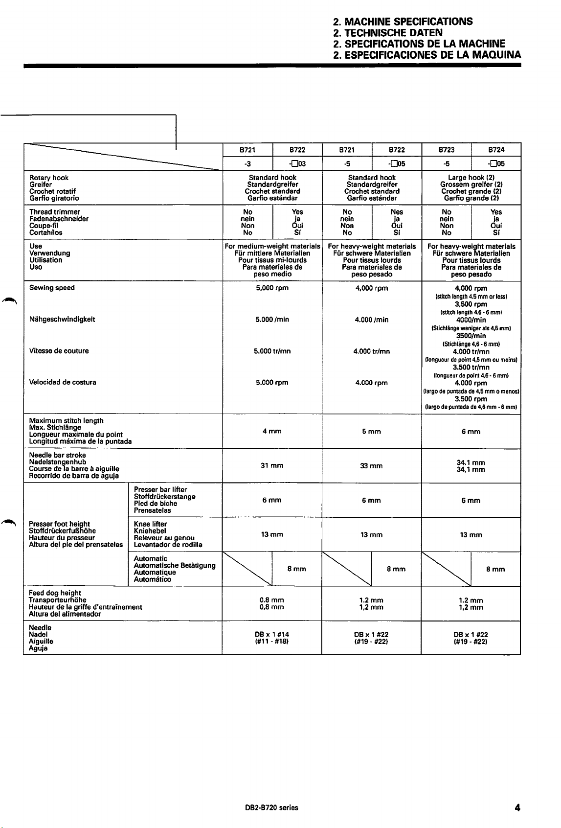
2.
MACHINE
2.
TECHNISCHE
2.
SPECIFICATIONS
2.
ESPECIFICACIONES
SPECIFICATIONS
DATEN
DE
LA
MACHINE
DE
LA
MAQUINA
~
Rotary hook
Greifer
Crochet rotatif Crochet standard
Garfio giratorio Garfio
Thread
trimmer
Fadenabschneider
Coupe-fil
Cortahnos No
Use
Verwendung
Utilisation
Uso
Sewing speed
~
Nahgeschwindigkeit
Vitesse de couture
Velocidad
Maximum stitch length
Stichliinge
Max.
Longueur maximale du point
Longitud maxima de
Needle bar stroke
Nadelstanlenhub
Course de a barre
Recorrido de barra
Presser
~
foot
StoffdruckerfuB ohe
Hauteur du presseur
Altura del
Feed
dog height
Transporteurhohe
Hauteur de
Altura del alimentador
Needle
Nadel
Aiguille
Aguja
de costura
Ia
puntada
a aiguille
de
aguja
heifiht
pie del prensatelas
Ia
griffe d'entrainement
Presser bar lifter
Stoffdruckerstange
Pied
de biche
Prensatelas
Knee
lifter
Kniehebel
Releveur
Levantador e
Automatic
Automatische Betatigung
Automatique
Automatico
au
J:enou
rodilla
For medium-weight materials
Fur mittlere Materialien
~
B721
-3
Standard hook
Standardgreifer
No
nein
Non
Pour tissus mi-lourds
Para
materiales de
peso medio
5,000 rpm
5.000/min
5.000tr/mn
5.000 rpm
o.amm
0,8mm
DB
(#11- #18)
estandar
4mm
31
mm
6mm
13mm
x 1 #14
B722
-D03
Yes
d~i
Si
8mm
B721
-5
Standard hook
Standardgreifer
Crochet standard
Garfio estandar
No
nein
Non Non Oui
No Si No
For heavy-weight materials
Fur schwere Materialien
Pour tissus lourds
Para
materiales de
peso pesado peso pesado
4,000
4.000/min
4.000tr/mn
4.000 rpm
I~
1.2mm 1.2mm
1,2mm
DB
(#19-
B722 B723
-005
Nes
rpm
Smm
33mm
6mm
13mm
8mm
x 1
#22
#22)
d~i
For
Fur
(Stichliinge
(longueur
(largo
(largo
~
-5
Large hook
Grossem greifer
Crochet grande
Garfio grande
No
nein
heavy-wei~t
schwere aterialien
Pour tissus
Para
materiales de
4,000 rpm
!stitch
length
3,500 rpm
(stitch
length
4000/min
3500/min
{Stichl~nge
4.000tr/mn
de
point
3.500tr/mn
{longueur
de
4.000 rpm
de
puntada
3.500 rpm
de
puntada
34.1
34,1
1,2mm
DB
(#19-
4.5
4.6
weniger
4,6
4,5
point
de
4,5
de
6mm
mm
mm
6mm
13mm
x 1 #22
#22)
B724
-005
(2)
(2)
(2)
(2)
Yes
ja
Si
materials
lourds
mm
or
less)
-6
mml
als
4,5
mml
-6
mml
mm
ou
moinsl
4,6
-6
mm)
mm o menos)
4,6
mm
-6
8mm
mml
DB2-B720 series
4
Page 24
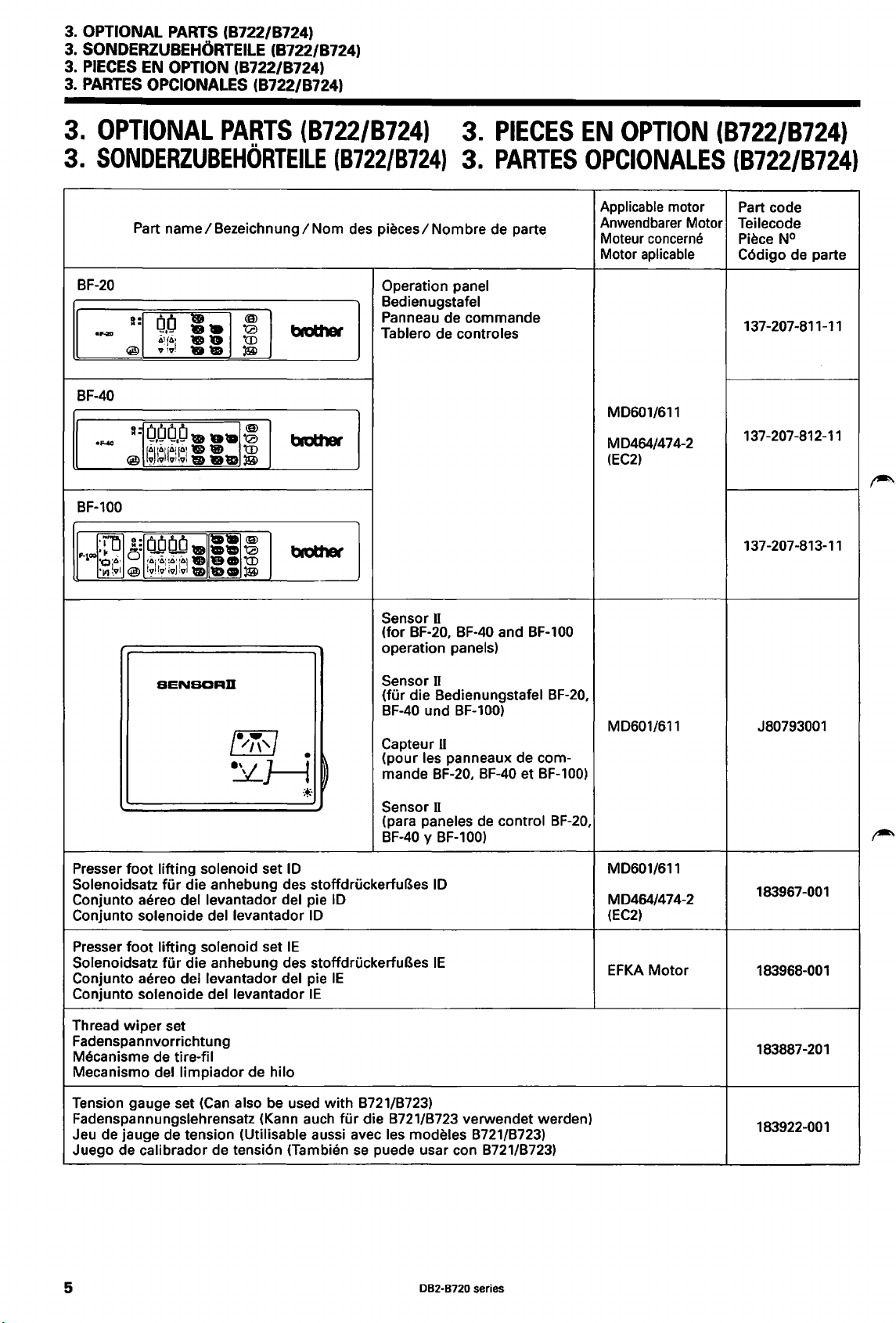
3.
OPTIONAL
3.
SONDERZU8EH0RTEILE (8722/8724)
3.
PIECES EN OPTION (8722/8724)
3.
PARTES
3.
OPTIONAL
3.
SONDERZU8EHQRTEILE
PARTS
OPCIONALES (8722/8724)
Part
name/8ezeichnung/Nom
(8722/8724)
PARTS
(8722/8724)
(8722/8724)
des
pieces/Nombre
3.
3.
PIECES
PARTES
de parte
EN
OPTION
OPCIONALES
Applicable motor Part code
Anwendbarer
Moteur
Motor
concerne
aplicable
(8722/8724)
(8722/8724)
Motor Teilecode
Piece N°
C6digo de parte
8F-20
8F-40
8F-100
SENBDRD
Operation panel
8edienugstafel
Panneau de commande
Tablero de controles
Sensor II
8F-20, 8F-40 and
(for
operation panels)
Sensor II
(fur die Bedienungstafel 8F-20,
BF-40
und 8F-100)
Capteur
(pour les panneaux de commande
U
8F-20,
BF-40
8F-1
00
et 8F-100)
MD601/611
MD464/474-2
(EC2)
MD601/611
137-207-811-11
137-207-812-11
137-207-813-11
J80793001
Sensor II
(para paneles
8F-40
y 8F-100)
Presser foot lifting solenoid set
Solenoidsatz
Conjunto aereo del levantador del pie
Conjunto solenoide
Presser foot lifting solenoid set
Solenoidsatz
Conjunto aereo del levantador del pie
Conjunto solenoide
Thread
Fadenspannv.orrichtung
Mecanisme de tire-fil
Mecanisme del limpiador de hila
Tension gauge set
Fadenspannungslehrensatz (Kann auch
Jeu de jauge de tension (Utilisable aussi avec les modeles 8721/8723)
Juego de calibrador de tensi6n (Tambien
wiper
fur
die anhebung des stoffdruckerfuBes
dellevantador
fOr
die anhebung des stoffdruckerfuBes
dellevantador
set
(Can
also be used with 8721/8723)
ID
IE
ID
IE
10
IE
fur
die 8721/8723 verwendet werden)
se
puede usar con 8721/8723)
ID
IE
de
control 8F-20,
MD601/611
MD464/474-2
(EC2)
EFKA
Motor
183967-001
183968-001
183887-201
183922-001
5
082-8720 series
Page 25
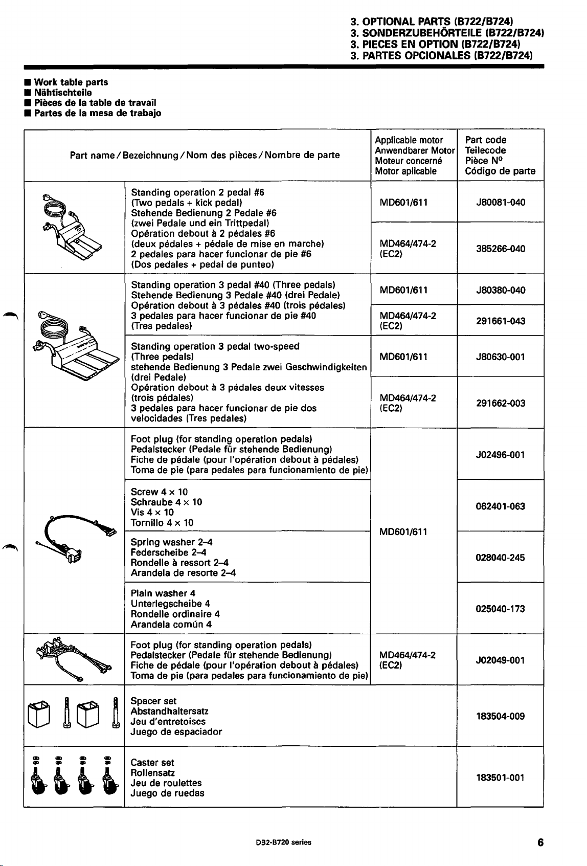
• Work table parts
• Nihtischteile
• Pieces
• Partes
de
Ia
table de travail
de
Ia
mesa
Part
name/Bezeichnung/Nom
de
trabajo
des
pieces/Nombre
de parte
3. OPTIONAL PARTS (8722/8724)
SONDERZU8EH0RTEILE (8722/8724)
3.
3.
PIECES
PARTES
3.
EN OPTION (8722/8724)
OPCIONALES (8722/8724)
Applicable motor Part code
Anwendbarer
Moteur
Motor
Motor Teilecode
concerne
aplicable
Piece
N°
C6digo de parte
Standing operation 2 pedal
(Two
pedals+
Stehende Bedienung 2 Pedale
(zwei Pedale und ein Trittpedal)
Operation
(deux pedales + pedale de mise
2 pedales para hacer funcionar de pie #6
(Dos pedales + pedal de punteo)
Standing operation 3 pedal
Stehende Bedienung 3 Pedale
Operation debout a 3 pedales #40 (trois pedales)
3 pedales para hacer funcionar de pie
(Tres
pedales)
Standing operation 3 pedal two-speed
(Three pedals)
stehende Bedienung 3 Pedale zwei Geschwindigkeiten
(drei Pedale)
Operation debout a 3 pedales deux vitesses
(trois pedales)
3 pedales para hacer funcionar de pie dos
velocidades
Foot plug (for standing operation pedals)
Pedalstecker (Pedale
Fiche de pedale (pour l'operation debout
Toma
de pie (para pedales para funcionamiento de pie)
kick pedal)
debout a 2 pedales
(Tres
pedales)
#6
#6
#6
en
marche)
#40
(Three pedals)
#40 (drei Pedale)
fur
stehende Bedienung)
#40
a pedales)
MD601/611
MD464/474-2
(EC2)
MD601/611
MD464/474-2
(EC2)
MD601/611
1--------+---------1
MD464/474-2
(EC2)
J80081-040
385266-040
J80380-040
291661-043
J80630-001
291662-003
J02496-001
Screw 4 x
Schraube 4 x
Vis4x
Tornillo 4 x
Spring washer
Federscheibe
Rondelle a ressort
Arandela de resorte
Plain washer 4
Unterlegscheibe 4
Rondelle ordinaire 4
Arandela
Foot plug (for standing operation pedals)
Pedalstecker (Pedale
Fiche de
Toma
Spacer set
Abstandhaltersatz
Jeu d'entretoises
Juego de espaciador
Caster set
Rollensatz
Jeu de roulettes
Juego de ruedas
10
10
10
10
2-4
2-4
2-4
2-4
comun 4
fOr
pedale (pour !'operation debout a pedales)
de pie (para pedales para funcionamiento de pie)
stehende Bedienung) MD464/474-2
MD601/611
(EC2)
062401-063
028040-245
025040-173
J02049-001
183504-009
183501-001
082·8720
series
6
Page 26
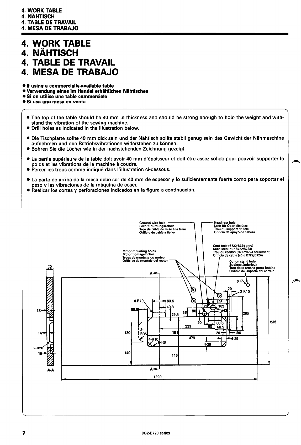
4.
WORK
4.
NAHTISCH
4.
TABLE
4.
MESA
4.
4.
4.
TABLE
DE
TRAVAIL
DE
TRABAJO
WORK TABLE
NAHTISCH
TABLE
DE
TRAVAIL
MESA
4.
•
If
using a commercially-available table
•
Verwendung eines
DE
TRABAJO
im
Handel erhiltlichen Nihtisches
• Si on utilise une table commerciale
• Si
usa una mesa en venta
• The
top
of
the table should
stand the vibration
• Drill holes
• Die
as
lischplatte
of
indicated in the illustration below.
sollte
aufnehmen und den Betriebsvibrationen widerstehen
be
40
mm
in thickness and should
the sewing machine.
40
mm
dick sein und der Nahtisch sollte stabil genug sein das Gewicht der Nahmaschine
zu
konnen.
• Bohren Sie die Locher wie in der nachstehenden Zeichnung gezeigt.
•
La
partie superieure de
poids et les vibrations de
•
Percer les trous comme indique dans !'illustration ci-dessous.
•
La
parte
de
arriba de
peso y las vibraciones de
• Realizar los cortes y perforaciones indicados
Ia
table doit avoir
Ia
machine a coudre. ,
Ia
mesa debe ser de
Ia
maquina de coser.
40
mm d'epaisseur et doit etre
40
mm de espesor y lo suficientemente fuerte como para soportar
en
Ia
figura a continuaci6n.
Ground wire hole
Loch fUr Erdungskabels
Trou de cable
Orificio de
------.
de
mise a
cable a tierra
be
strong enough to hold the weight and with-
assez
solide pour pouvoir supporter le
Head rest hole
Loch fUr Oberteilstutze
Ia
terre
Trou du support de
Orificio de apoyo de cabeza
tAte
el
,.,.
.....
,
40
A-A
Motor
mounting holes
Motormontagelocher
Trous de montage du
Orificios de montaje del
140
1200
moteur
motor
181
110
339
479
Cord hole 18722/8724 only)
(nur 872218724)
Kabelloch
Trou
du
cordon (872218724 seulement)
Orificio de cable
(s61o
8722/8724)
Cotton stand hole
Spulenstanderloch
Trou de Ia broche porte-bobine
Orificio
del soporte del carrete
535
7
082-8720 series
Page 27
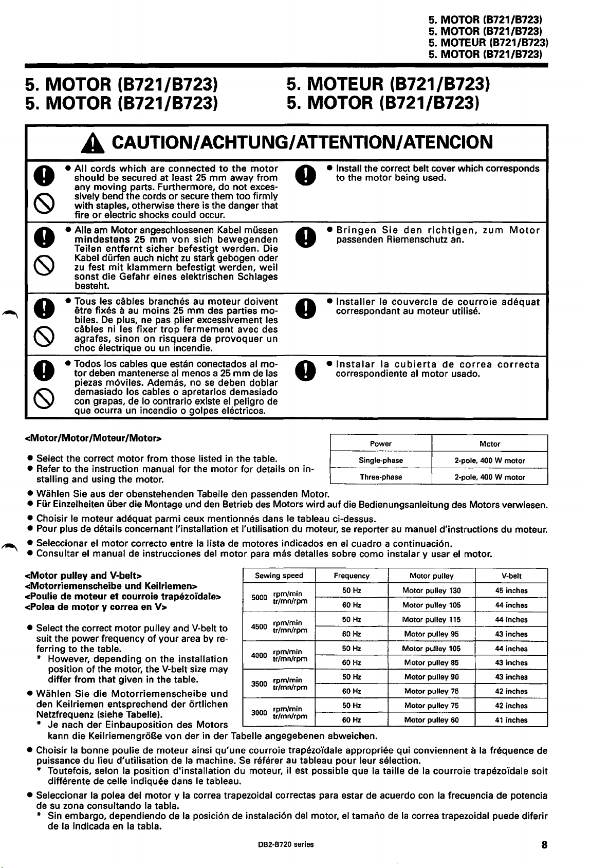
5.
MOTOR (8721/8723)
5.
MOTOR (8721/8723)
£ CAUTION/ ACHTUNG/ ATTENTION/ ATENCION
5.
MOTOR (8721/8723)
5.
MOTOR (8721/8723)
5.
MOTEUR (8721/8723)
5.
MOTOR (8721/8723)
5.
MOTEUR (8721/8723)
5.
MOTOR (8721/8723)
•
All
cords
0
~
0
~
0
~
0
~
<Motor
• Select the correct
• Refer
stalling and using the motor.
• Wahlen Sie aus der obenstehenden Tabella den passenden Motor.
• Fur Einzelheiten uber die Montage und den Betrieb
• Choisir
• Pour plus de details concernant !'installation et !'utilisation du moteur,
• Seleccionar
• Consultar
should be secured at least
any moving parts. Furthermore, do not excessively bend the cords
with staples, otherwise there is the danger that
fire
• Aile am
mindestens
Teilen
Kabel durfen auch nicht
zu
fest
sonst die Gefahr eines elektrischen
besteht.
• Taus les cables branches au
etre fixes a
biles.
cables ni les
agrafes, sinon on risquera de
choc electrique au un incendie.
• Todos los cables que estan conectados
tor
piezas
demasiado los cables o apretarlos demasiado
con grapas, de
que ocurra un incendio o golpes electricos.
/Motor
to
the instruction manual
le
moteur adequat parmi ceux mentionnes dans le tableau ci-dessus.
el
which
or
electric shocks could occur.
Motor
entfernt
mit
De
plus, ne pas plier excessivement les
deben mantenerse
m6viles. Ademas, no
/Moteur
motor
el
motor
manual de instrucciones del
are connected
or
secure them too firmly
angeschlossenen Kabel mussen
25
mm
von
sicher befestigt werden. Die
klammern befestigt warden, weil
au
mains
fixer
Ia contrario existe
/Motor>
from those listed in the table.
correcto entre
25
trap
al
zu
menos a
for
mm
fermement
to
the
25
mm
sich
bewegenden
stark gebogen oder
moteur
des parties mo-
provoquer
se
deben doblar
the
motor
Ia
Jista
motor
away from to the
Schlages
doivent
avec des
un
al
25
el
de motores indicados
motor
rna-
mm
de
las
peligro de
for
details on in-
des
para mas detalles sabre como instalar y usar
0
0
0
0
Motors wird auf die Bedienungsanleitung
• Install the correct belt cover which corresponds
•
•
•
en
motor
being used.
Bri
ngen
Sie
den
passenden Riemenschutz an.
Installer
correspondant
lnstalar
correspondiente
se
el
le
couvercle
Ia
cubierta
Power
Single-phase
Three-phase
reporter
cuadro a continuaci6n.
au
richtigen,
au
al
manuel d'instructions du moteur.
de
moteur utilise.
de
motor
usado.
2-pole, 400
2-pole,
des
el
zum
Motor
courroie
correa
Motors verwiesen.
motor.
Motor
W motor
400
W motor
adequat
correcta
<Motor
<Motorriemenscheibe und Keilriemen>
<Poulie de
<Polea de
•
pulley and V-belt>
moteur
motor
Select the correct motor pulley and V-belt to
suit the power frequency
ferring
to
et
y correa en V>
the table.
courroie trapezoidale>
of
your area by re-
* However, depending on the installation
of
position
differ from that given in the table.
• Wahlen Sie die
den Keilriemen entsprechend der
Netzfrequenz (siehe Tabelle).
* Je nach
kann die KeilriemengroBe von der in der Tabella angegebenen abweichen.
• Choisir
puissance du lieu d'utilisation de
* Toutefois, selon
differente de
• Seleccionar
su
zona consultando
de
the motor, the V-belt
Motorriemenscheibe
der
Einbauposition des Motors
Ia
bonne poulie de moteur ainsi qu'une courroie trapezo'idale appropriee qui conviennent a
Ia
position d'installation du moteur, il est possible que
celle indiquee dans
Ia
polea del
motor y Ia
Ia
tabla.
* Sin embargo, dependiendo de
Ia
de
indicada
en
Ia
tabla.
size
may
und
ortlichen
Ia
machine.
le
tableau.
correa trapezoidal correctas para estar de acuerdo con
Ia
posicion de instalaci6n del motor,
Sewing speed
5000
4500
4000
3500
3000
Se
referer
082-8720 series
rpm/min
tr/mn/rpm
rpm/min
tr/mn/rpm
rpm/min
tr/mn/rpm
rpm/min
tr/mn/rpm
rpm/min
tr/mn/rpm
au
tableau pour leur selection.
Frequency
50
Hz
60Hz
50
Hz
60Hz
50
Hz
60Hz
50
Hz
60Hz
50
Hz
60Hz
el
tamaiio de
Ia
taille de
Motor pulley
Motor pulley
Motor pulley
Motor pulley
Motor pulley
Motor pulley
Motor pulley
Motor pulley
Motor pulley
Motor pulley
Motor pulley
Ia
correa trapezoidal puede diferir
130
105
115
95
105
85
90
75
75
60
Ia
courroie trapezo'idale soit
Ia
frecuencia de potencia
V-belt
45
inches
44inches
44inches
43
inches
44inches
43
inches
43
inches
42
inches
42
inches
41
inches
Ia
frequence de
8
Page 28
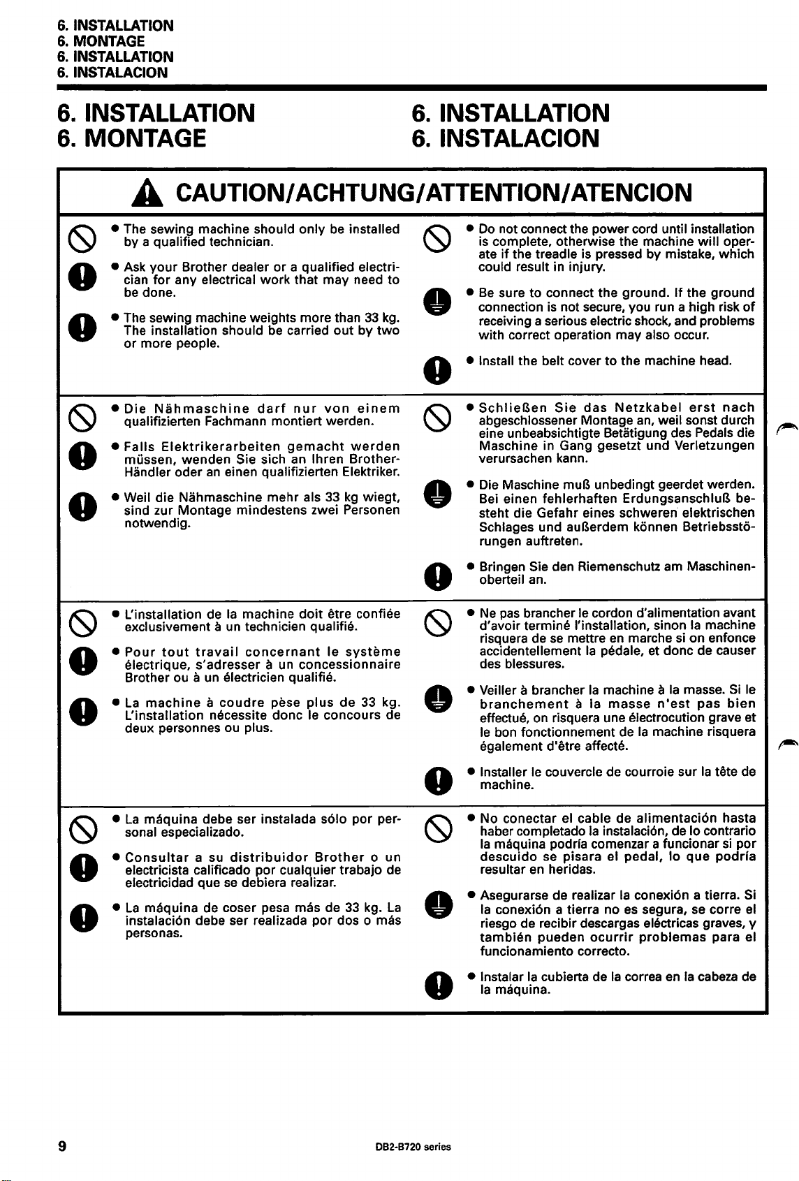
6.
INSTALLATION
6.
MONTAGE
6.
INSTALLATION
6.
INSTALACION
6.
INSTALLATION
6.
MONTAGE
6.
INSTALLATION
6.
INSTALACION
• The sewing machine should only be installed
~
• Ask
•
• The sewing machine weights more than
•
•
~
• Falls
•
• Weil die Nahmaschine
•
A
by a qualified technician.
cian
be
The installation should be carried
or
Die
qualifizierten Fachmann montiert werden.
mussen, wenden Sie sich
Handler oder
sind zur Montage mindestens zwei Personen
notwendig.
CAUTION/
your
Brother dealer or a qualified electri-
for
any electrical
done.
more people.
Nahmaschine
Elektrikerarbeiten
an
einen qualifizierten Elektriker.
ACHTUNG/
work
that may need to
out
darf
nur
von
gemacht
an
lhren Brother-
mehr
als
33
33
by
two
einem
werden
kg
wiegt,
kg
ATTENTION/ ATENCION
•
Do
not connect the power cord until installation
~
.
•
•
~
•
is complete, otherwise the machine
if
the treadle is pressed by mistake, which
ate
could result in injury.
•
Be
sure to connect the ground.
connection is not secure, you run a high risk
receiving a serious electric shock, and problems
with correct operation may also occur.
• Install the belt cover to the machine head .
•
SchlieBen
abgeschlossener Montage
eine unbeabsichtigte Betatigung des Pedals die
Maschine in Gang gesetzt und Verletzungen
verursachen kann.
• Die Maschine muB unbedingt geerdet werden .
Bei einen fehlerhaften ErdungsanschluB besteht die Gefahr eines
Schlages und
rungen auftreten.
• Bringen Sie den Riemenschutz am Maschinenoberteil an.
Sie
das
Netzkabel
schweren· elektrischen
auBerdem konnen Betriebssto-
will
If
the ground
an,
erst
weil sonst durch
oper-
of
nach
• L'installation de
~
•
•
•
•
•
~
•
•
•
•
Ia
exclusivement
Pour
tout
electrique, s'adresser
Brother ou
La
machine a coudre
L'installation necessite done le concours de
deux personnes ou plus.
La
maquina debe ser instalada
sonal especializado.
Consultar
electricista calificado por cualquier trabajo de
electricidad que
La
maquina de coser pesa mas de
instalaci6n debe ser realizada por dos o mas
personas.
travail
a
a su
machine
a un technician qualifie.
concernant
un
electrician qualifie.
distribuidor
se
debiera realizar.
doit
etre confiee
le
a un concessionnaire
pese
systeme
plus
de
33
s61o
por per-
Brother o un
33
kg.
kg .
La
•
•
~
• Veiller a brancher
•
• Installer le couvercle de courroie sur
•
• No conectar el cable de alimentaci6n hasta
~
• Asegurarse de realizar
•
• lnstalar
Ne
pas
d'avoir termine !'installation, sinon
risquera de
accidentellement
des blessures.
branchement
effectue, on risquera une electrocution grave et
le
egalement d'etre affecte.
machine.
haber completado
Ia
descuido
resultar
Ia
riesgo de recibir descargas electricas graves, y
tambien
funcionamiento correcto .
Ia
brancher le cordon d'alimentation avant
se
mettre
bon fonctionnement de
maquina pod ria comenzar a funcionar
conexi6n a tierra no
maquina.
se pisara el pedal,
en
heridas.
pueden
Ia
cubierta de
en
marche si on enfonce
Ia
pedale, et done de causer
Ia
machine a
a Ia
masse
Ia
Ia
instalaci6n, de lo contrario
Ia
conexi6n a tierra. Si
es
segura, se corre
ocurrir
problemas
Ia
correa
Ia
machine
Ia
masse. Si le
n'est
pas
machine risquera
Ia
lo
que
en
Ia
cabeza
bien
tete de
si
por
podrra
el
para el
de
•
9
082-8720 series
Page 29

6-1. Installing the oil pan
6-1. Montage der
6-1. Installation
6-1. lnstalacion de
Olwanne
du
reservoir d'huile
Ia
bandeja de aceite
6.
INSTALLATION
6.
MONTAGE
&.INSTALLATION
6.
INSTALACION
1.
Insert the four oil
below so that the four corner holes are aligned.
1.
Setzen Sie die vier Olwannenauflagen 8 von unten her
in die
Olwanne
aufeinander ausgerichtet sind.
1.
lnserer les quatre tampons 8 du reservoir d'huile dans
le reservoir d'huile 0 par le cote inferieur de maniere
que les trous aux quatre coins soient
1.
lnsertar las cuatro almohadillas de
8
en
Ia
las esquinas queden alineados.
2.
Place
that corners are aligned.
3.
Place
the
••
2.
Setzen
Sie die
3.
Legen Sie die
Ecken
••
2.
Placer le reservoir d'huile 0 dans
de travail de maniere que
3.
Placer les quatre tampons de tete 3 sur les quatre coins
du reservoir d'huile
claus
2.
Colocar
de
alineadas.
3.
Colocar las cuatro almohadillas de
de las esquinas de
asegurarlas con cuatro clavos
bandeja de aceite 0 desde abajo de manera que
the oil
the four head cushions 8 on top
oil pan
Sie die Olwanne 0
Ecken
der Olwanne 0 und befestigen Sie die
8.
Ia
trabajo
pan
cushions 8 into the oil pan 0 from
0,
so daB die Locher an den Ecken
alignes.
Ia
bandeja de aceite
pan
0 into the groove in the work table so
of
the corners in
0,
and then secure them with the
in
die Nahtischnut und richten
aufeinander aus.
vier
Auflagen 8 des Oberteils
Ia
rainure de
les
quatre coins soient alignes.
o,
puis les fixer a !'aide des quatre
bandeja de aceite 0
de
manera
Ia
bandeja de aceite
que
en
Ia
ranura de
las
esquinas
Ia
cabeza 8 encima
8.
four
mit
queden
8,
auf
Nageln
Ia
Ia
y luego
nails
die
table
mesa
4.
Insert the
work table, and then secure them
4.
Setzen
Aussparungen
Nageln
4.
lnserer les deux
crans de
quatre claus
4.
lnsertar las dos almohadillas de caucho 8
de
clavos
two
rubber cushions 8 into the notches in the
Sie
die
beiden
des
Nahtisches und befestigen Sie die
Gummiauflagen
0.
tampons
Ia
table de travail, puis les fixer a l'aide des
en caoutchouc 8 dans les
0.
Ia
mesa de trabajo, y luego asegurarlas con cuatro
0.
with
the four nails
8
en
las ranuras
in
e.
die
mit
082-8720 series
10
Page 30

6.
INSTALLATION
6.
MONTAGE
6.
INSTALLATION
6.
INSTALACION
6-2. Installing
Montage
6-2.
6-2.
Installation de
6-2.
lnstalacion de
the
machine head
des Maschinenoberteils
Ia
tete
de machine
Ia
cabeza de Ia maquina
1.
Insert the knee lifter complying bar
1.
Die Knieheberstange 0 einsetzen.
1.
lntroduire
1.
lntroducir
rodilla
2.
Insert the
bed.
3.
Clamp the hinges 8 onto the rubber cushions 8 in the
work table, and then place the machine head onto the
head cushions
ners.
4.
Tap
NOTE:
Ia
barre de liaison de genouillere
Ia
barra de
transmisi6n
0.
two
hinges 8
into
8 which are on
the head rest 8 into the table hole.
Tap
the head rest securely into the table hole.
If
the head rest is
go,
the
stable when
machine head
not
it
is tilted back. ·
0.
0.
del levantador de
the holes in the machine
top
of
the oil pan cor-
pushed in
will
not
as
far
as
be
sufficiently
it
will
2.
Setzen Sie die beiden Scharniere 8 in die Locher des
Maschinenunterteils.
3.
Klemmen Sie die Scharniere 8
8 im Nahtisch fest und setzen Sie das Oberteil
Auflagen
befinden.
4.
Schlagen Sie die Oberteilstutze 8 in das Lock im
HINWEIS: Die Oberteilstutze muB richtig im Loch des
0
2.
lnserer les deux charnieres 8 dans les trous du plateau de machine.
3.
Accrocher les charnieres 8 sur les tampons
les tampons de
4.
lntroduire
REMARQUE:
2.
lnsertar las dos bisagras 8
3.
Enganchar las bisagras 8
maquina
aceite.
4.
Colocar a presi6n
NOTA: Asegurarse de que
Si
quedara bien astable
tete 8 situes sur les coins du reservoir d'huile.
le
support de tete 8 dans le trou de table
Tapoter le support de tete pour
Si
Je
support de tete n'est
lorsqu'on l'inclinera vers l'arriere.
en
los orificios
en
las almohadillas de caucho 8
en
las almohadillas de
el
soporte de cabeza 8
el
soporte de cabeza no
Ia
cabeza
el
soporte de cabeza
ha
at
inclinarla hacia atras.
en
caoutchouc 8 de
en
Ia
Ia
mettre fermement
pas
poussee bien a fond,
en
Ia
mesa de trabajo.
8 que
se
encuentran
en
el
orificio de
ha
quedado bien colocado
tapotant.
Ia
quedado bien colocado
en
mesa.
8,
die
sich an
Tische sitzen.
Falls
die
gedruckt
Umklappen des
hinten nicht sicher.
Ia
table de travail, puis placer
en
place dans
Ia
tete de machine
Ia
mesa de trabajo, y luego colocar
en
Ia
parte de arriba de las esquinas de
en
el
orificio de
Oberteilstutze
en
el
orificio de
Ia
mesa,
den
wird,
steht
Maschinenoberteils
Je
trou de table.
ne
sera
Ia
cabeza de
an
den Gummiauflagen
Ecken
Ia
pas
Ia
der
Olwanne
nicht
die
suffisamment stable
mesa.
ganz
Maschine
tete de machine sur
Ia
cabeza de
Ia
bandeja de
Ia
maquina no
auf
die
lisch.
hinein
beim
nach
r-
Ia
11
082-8720 series
Page 31

6. INSTALLATION
6.
MONTAGE
6.
INSTALLATION
6.1NSTALACION
6-3. Installing
6-3.
Montage
6-3. Installation de
the
knee
lifter
assembly (Except
der Kniehebel (auBer
I'
ensemble de releveur au genou (Sauf
-900)
-900)
-900)
6-3. lnstalacion del conjunto del levantador de rodilla (Excepto
1.
Place
the knee lifter assembly 0 onto the knee lifter bar
f)
on the oil pan, and then secure
f).
bolt
1.
Bringen
Olwanne
1.
Placer !'ensemble 0 de releveur
de releveur
le fixer
1.
Colocar
del levantador de
luego asegurarla apretando
2. Adjust the knee lifter.
1) Turn the machine pulley so
2)
2. Stellen Sie den Kniehebel ein.
1) Drehen Sie die Riemenscheibe urn den Transporteur
2)
Regier le releveur
2.
1) Tourner
Sie
den
Kniehebel 0 an
an
und befestigen
au
genou situe sur le reservoir d'huile, puis
en
serrant
el
conjunto del levantador de rodilla 0
low
the
top
Lower the presser
e.
lifter
unter die Stichplatte abzusenken.
Senken
StoffdruckerfBhebel 8 ab.
Ia
d'entrainement soit
le
rodilla
of
the needle plate.
Sie
den
au
poulie de machine de maniere que
Sie
boulon
f)
foot
8 by using the presser bar
StoffdruckerfuB
genou.
placee sous le haut de
a aiguille.
2)
Abaisser le pied presseur 8
de barre de pied presseur.
Withinf
13
innerhalbe
mm
13
mm
2. Ajuste del levantador de
1)
Girar
Ia
polea
se
alimentador
Ia
placa de aguja.
de
2)
Bajar
el
prensatelas 8 usando
de prensatelas
3)
Loosen the
4)
Turn the screw 0 to adjust so that the amount
in the knee lifter
knee lifter plate
5) Securely tighten the nut
6) Loosen the nut
7)
Turn the screw
of
the screw
8mm.
8)
Turn
the
presser foot 8 is at the desired position within a dis-
of
tance
lifter plate
9}
After adjustment
3)
Losen Sie die Mutter
4)
Drehen Sie die Schraube
8
auf
Kniehebelplatte 0 Ieicht gedruckt wird.
5)
Ziehen Sie die Mutter 8 wieder fest.
6)
Losen Sie die Mutter
7)
Drehen
zwischen der Schraube
ungefahr 8
8)
Stellen Sie
ungefahr 2 mm
encuentre debajo de
e.
nut
8.
8.
G>
G>
and the knee lifter 8 is approximately
adjusting
13
mm
0 is fully pressed.
is
Sie
die
mm
mit
der Schraube
8 so ein, daB er sich bei
Kniehebel 0 in
Stichplatte befindet.
9)
Ziehen Sie nach abgeschlossener Einstellung
Mutter
0 wieder fest.
rodilla.
de
Ia
maquina
8 is approximately 2
0 is gently pressed.
until the distance between the end
screw
of
the needle plate when the knee
completed, securely tighten the nut
0.
0.
Schraube
G>
einzustellen.
einem
-900)
it
by tightening the
der Kniehebelstange
sie
mit
der Schraube
au
genou sur l'arbre
f).
en
Ia
bandeja de aceite, y
el
perno
8.
that
the feed dog is be-
8
mit
Ia
en
utilisant le releveur 8
de
manera
Ia
parte superior
el
levantador de barra
mm
when the
0.
G>
to
adjust
0,
urn das Kniehebelspiel
einzustellen,
Gf),
urn
und dem Kniehebel 8
41>
den StoffdruckerfuB
vollstandig
Abstand
so
wenn
den
gedrucktem
von
13
Abstand
f)
8.
en
el
dem
Ia
griffe
plaque
que
of
that
mm
der
f)
eje
el
play
the
0.
die
auf
zur
die
DB2-B720 series
12
Page 32

6.
INSTALLATION
6.
MONTAGE
6.
INSTALLATION
6.1NSTALACION
t .
A
13
mm au
A13mm
max1mum
3)
Desserrer l'ecrou
4)
Tourner
du
lorsqu'on
releveur
5)
Bien serrer l'ecrou
6)
Desserrer I' ecrou
7)
Tourner
l'extremite de
d'environ 8 mm.
8)
Tourner
presseur
maximum de
du releveur
9)
Une fois le reglage termine, bien serrer l'ecrou
3)
Aflojar
4)
Girar
del levantador de rodilla 8
mm
de
5)
Apretar fuertemente
6)
Aflojar
7)
Girar
extremo del tornillo
aproximadamente 8 mm.
8)
Girar
que
13
completamente
9)
Despues
fuertemente
Ia
releveur
au
Ia
Ia
8
el
tornillo
el
tornillo 8 para ajustar de manera que
al
presionar suavemente
rodilla
0.
Ia
tuerca
el
tornillo
el
tornillo de ajuste
el
prensatelas 8 quede
mm
de Ia placa de aguja cuando se presiona
0.
vis 8 de maniere que
au
genou 8 soit
appuie
doucement
genou.
Ia
quantite de jeu
d'environ 2 mm
sur
Ia
plaque 0
0.
8.
vis
CD>
jusqu'a
Ia
vis
vis de reglage
soit a Ia
Ia
plaque a aiguille lorsque
au
genou est completement enfoncee.
ce que
CD>
et le releveur
4D
position desiree a
Ia
de maniere que le pied
distance entre
au
genou 8 soit
0.
sea
aproximadamente 2
Ia
placa de levantador
Ia
tuerca
0.
que
Ia
distancia entre el
«!>
para ajustar de manera
en
Ia
posici6n deseada a
completamente,
de
Ia
8.
G>
hasta
G)
y ellevantador de rodilla 8
Ia
placa de levantador de rodilla
ajustar
tuerca
8.
13
mm
Ia
plaque 0
el
apretar
du
au
8.
juego
sea
0.
6-4. Installing
the
belt
6-4. Riemenmontage
6-4.
Installation de
6-4.
lnstalacion de
Ia
Ia
courroie
correa
1.
Tilt back the machine head, and then place the belt 0
onto the
2.
Turn the
mm
the midway point with a force
1.
Klappen Sie das Maschinenoberteil zuruck und bringen
Sie den Riemen
und der Nahmaschine an.
2.
Stellen Sie die Riemenspannung
8 ein, so daB der Riemen
wenn er in der
belastet wird.
1.
Incliner
courroie 0 sur
machine.
2.
Tourner les deux ecrous 8 pour regler de maniere que
Ia
appuie
(500gf).
1.
lnclinar
colocar
de
2.
Girar
una deflexi6n de
se
motor
pulley and the machine pulley.
two
nuts 8 to adjust so that there is
of
deflection in the V-belt 0 when
0 an der Riemenscheibe des Motors
Mitte
Ia
t~te
de machine vers l'arriere, puis placer
Ia
poulie de moteur et
courroie
Ia
presiona
en
V 0 s'enfonce de
au
milieu de
Ia
cabeza de
Ia
correa 0 sabre
maquina.
las
dos tuercas 8 para ajustar
10 -14
en
el
medio con una fuerza de
10-
mit
einer Kraft von 4,9 N (500gf)
Ia
courroie avec une force de 4,9 N
Ia
maquina hacia atras, y luego
Ia
mm
of
4.9
mit
den beiden Muttern
14
mm
10 a 14
polea del
de
en
Ia
correa
10 -14
it
is pressed at
N (500gf).
eingedruckt wird,
sur
Ia
poulie de
mm
lorsqu'on
motor y Ia
manera que haya
en
V 0 cuando
4,9
N (500gf).
r-
Ia
polea
13
082-8720 series
Page 33

6-5. Installing the bobbin winder
6-5. Montage des
6-5. Installation
lnstalaci6n de
6-5.
Spulers
du
bobineur· de canette
Ia
bobinadora
&.INSTALLATION
6. MONTAGE
INSTALLATION
6.
6.1NSTALACION
1.
Push
down
go.
2. Place the bobbin
belt 8
bin
winder 8 so
work
the
the bobbin presser
by
approximately 5 mm, and then place the bob-
table.
3. Install the bobbin
two
screws
e.
winder
that
wheel
it
is parallel
winder 8 to
arm
0 as
far
f)
so that
with
the work table
it
pushes the
the belt hole in
as
with
it
will
the
4. Pull the bobbin presser arm 0 back and check that there
approximately 8
is
bin
winder
1.
Drucken Sie den Spulenarm 0 so
unten.
2. Positionieren Sie das Spulerrad
wheel
8 urn ungefahr 5
den Spuler 8 parallel zur Riemenoffnung
mm
of
f)
and the belt
mm
eingedruckt
clearance between the bob-
8.
weit
wie moglich nach
f),
so daB der Riemen
wird
und richten Sie
im
Nahtisch
a us.
3.
Befestigen Sie den Spuler 8
mit
den beiden Schrauben
8 am Nahtisch.
4.
Ziehen Sie den Spulenarm 0 zuruck und kontrollieren
ob der Abstand zwischen dem Spulerrad
Sie,
Riemen
8 ungefahr 8
mm
betragt.
f)
und dem
1.
Abaisser
2.
Placer
qu'elle pousse
le
courroie dans
3.
Installer le bobineur de canette 8 sur
4.
Tirer le bras 0 du presseur de canette vers l'arriere et verifier qu'il y ait un ecart d'environ 8
et
Ia
bobineur de canette
1.
Empujar hacia abajo tanto como sea posible el brazo presionador de
2.
Colocar
bobinadora 8 de manera que quede paralela con
3.
lnstalar
4.
Tirar del brazo presionador de
mm
Ia
rueda de
Ia
bobinadora 8
entre
Ia
rueda de
courroie
Ia
bobinadora
en
Ia
bobinadora
Ia
mesa de trabajo con los dos tornillos
Ia
Ia
table de travail a l'aide des deux vis
8.
f)
de manera que empuje
el
orificio de
bobina 0 hacia atras y verificar que exista una separaci6n de aproximadamente 8
f)
y
Ia
correa
8.
Ia
au
maximum le bras 0 du presseur de canette.
Ia
roue 8 du
bobineur
de
bobineur
Ia
courroie 8 d'environ 5 mm, puis placer
canette 8
Ia
table de travail.
e.
Ia
correa 8 aproximadamente 5
Ia
bobina
correa
0.
0.
en
Ia
mesa de trabajo.
de canette de maniere
parallelement
mm
entre
mm,
au
trou
Ia
roue 8 du
y luego colocar
de
Ia
082-8720 series 14
Page 34

6.
INSTALLATION
6.
MONTAGE
6.
INSTALLATION
6.
INSTALACION
6-6. Installing the belt cover
6-6. Montage des Riemenschutzes
Installation
6-6.
6-6.
lnstalacion de
du
couvercle de courroie
Ia
cubierta de
Ia
correa
1.
Loosen the three screws 0 on the machine side plate by
2.
Tilt back the machine head, align the groove in the belt cover
securely tighten screw
1.
Losen Sie die drei Schrauben 0
2.
Klappen Sie das Maschiennoberteil zuruck, richten Sie die Nut des Riemenschutzes
Schrauben
1.
Desserrer
2.
Incliner
les trois vis
1.
Aflojar los tres tornillos 0 de
2.
lnclinar
tres tornillos
0 aus und ziehen Sie nur die Schraube 0-A fest.
les
trois vis 0 de
Ia
tf!te de machine vers l'arriere, aligner
0,
puis serrer fermement
Ia
cabeza
0,
0-A
only.
an
der seitlichen Maschinenplatte urn 4 bis 5 Umdrehungen.
Ia
plaque laterale de machine de 4 a 5 tours.
Ia
vis 0-A seulement.
Ia
placa lateral de
de
Ia
y luego apretar fuertemente
maquina hacia atras, alinear
Ia
rainure du couvercle
Ia
s61o
el
4-
5 turns.
f)
with
the stud 8 and the three screws
f)
maquina 4 - 5 vueltas.
Ia
ranura de
tornillo 0-A.
Ia
cubierta de
de courroie avec
Ia
correa
f)
auf
den Zapfen 8 und die drei
le
clou a grosse tf!te 8 et
f)
con
el
esparrago 8 y los
0,
and then
r-'
15
082-8720 series
Page 35

6.
INSTALLATION
6.
MONTAGE
6.
INSTALLATION
6.
INSTALACION
3.
Return the machine head
then remove the screw
head.
4.
Align screw 0-B
and then place belt cover U 0 onto the machine pulley.
5.
Tighten screws 0-B,
with
to
its original position, and
8 from the rear
the groove 0 in belt cover U
0-C
and 8 to secure belt cover U
of
the machine
·
••
3.
Richten Sie das
entfernen Sie die Schraube
· Maschinenoberteils.
4.
Richten Sie die Schraube 0-B
menschutzes
U 0
utz
5.
Ziehen Sie die Schrauben 0-B, 8-C und 8 fest, urn den
Riemenschutz
3.
Remettre
retirer
4.
Aligner
courroie
Ia
5.
Serrer les vis 0-B,
de courroie
an
Ia
Ia
vis 8 de l'arriere de
Ia
vis 8-B avec
U,
poulie de machine.
Maschinenoberteil
8
U 0 aus und bringen Sie den Riemensch-
der Riemenscheibe der Maschine an.
U 0
zu
befestigen.
tete de machine a
Ia
puis placer
U.
le
0-C
sa
Ia
rainure 0 du couvercle 0 de
couvercle 0 de courroie U sur
et 8 pour fixer le couvercle 0
wieder
auf
der Ruckseite des
auf
die
Nut
position initiale, puis
tete de machine.
auf
0 des Rie-
0,
und
3.
Volver
de
4.
Alinear
Ia
0
5.
Apretar
cubierta de
6.
6.
Sie die Schraube
6.
Ia
cabeza de
luego quitar
Ia
correa U
en
Place
by 2 - 3
screws
Bringen Sie den Riemenschutz D 8 so an, daB er den
Riemenschutz
el
maquina.
el
tornillo 0-B con
0,
Ia
polea de
los
tornillos
Ia
belt cover D 8 so that
mm,
0.
Ia
maquina a
tornillo 8 de
Ia
Ia
y luego colocar
Ia
maquina.
0-B, 0-C y 8 para asegurar
correa U
and then
0.
provisionally
8 und 2 bis 3
Ia
posicion original, y
parte trasera de
ranura 0
Ia
it
overlaps the belt cover 8
mm
en
cubierta de
tighten
uberlappt und ziehen
Ia
Ia
cubierta de
Ia
correa U
the
8 provisorisch fest.
Placer le couvercle 8 de courroie D de maniere
chevauche le couvercle 8 de courroie de 2-3 mm, puis
serrer provisoirement
les deux vis
0.
cabeza
Ia
two
qu'il
6.
0
2-3mm
2.6mm
Colocar
superponga a
y
2,6mm
082-8720 series
Ia
cubierta de
Ia
luego apretar provisional mente los dos tornillos
Ia
correa D 8 de manera que
cubierta de
Ia
correa 8 unos 2 - 3 mm,
se
0.
16
Page 36

6.
INSTALLATION
6.
MONTAGE
6.
INSTALLATION
6.
INSTALACION
7.
Insert the cover 0
cover
f)
groove of
8.
~\
(",
\
\
\
Slide the cover 0 down along the groove
D
f)
as
7.
Bringen Sie die Abdeckung 0 des Riemenschutzes D
f)
zwischen dem Riemenschutz
menschutz
Riemenschutzes
8.
Schieben Sie die Abdeckung 0 entlang der
Riemenschutzes
~~
7.
lnserer
entre
le couvercle
courroie
8 de courroie
8.
Faire glisser bien a fond le couvercle 0 vers
long
de
7.
lnsertar
entre
Ia
correa D
de
Ia
correa D
8.
Deslizar
de
Ia
cubierta de
of
belt cover D 8 in between the belt
and belt cover D
belt cover D
far
as
it
will go.
D
f)
an
D
f)
le
couvercle 0 du couvercle 8 de courroie D
D,
Ia
rainure du couvercle 8 de courroie
Ia
cubierta
cubierta de
f),
y luego colocarla
Ia
cubierta 0 hacia abajo a lo largo de
f)
puis le placer dans
D.
f).
Ia
f),
and then place
f).
und setzen Sie sie in die Nutdes
f)
ein.
ganz nach unten.
de courroie et le couvercle
C!)
de
Ia
cubierta de
Ia
correa
correa D 8 tanto como
f)
Ia
rainure du couvercle
f)
y
Ia
en
Ia
ranura
it
into the
of
belt cover
und
dem Rie-
Nut
le
bas le
D.
Ia
correa D
cubierta de
de
Ia
cubierta
Ia
ranura
sea
posible.
f)
des
de
f)
Ia
r-"'
\\\
X X 0
9.
Tirer le couvercle 8
le couvercle
10.
Serrer completement les deux vis
9.
Tirar de
correa
10.
Apretar fuertemente los dos tornillos
C!)
Ia
cubierta de
f)
y
Ia
de
du couvercle 8 de courroie
cubierta 0 de
courroie D vers soi jusqu'a
Ia
correa D
Ia
correa D
9.
Pull belt cover D
ance between the belt cover
cover D
10.
Fully tighten the
9.
Ziehen Sie am Riemenschutz D
dem Riemenschutz
Riemenschutzes
10.
Ziehen
6.)
ce
qu'il
ne
D.
8.
(Se
reporter a l'etape
f)
hacia adelante hasta que no quede ninguna separaci6n entre
reste plus d'ecart entre le couvercle
6.)
8.
Sie
f)
toward you until there is
f)
two
screws
f)
D
f)
die beiden Schrauben 0 fest. (Siehe Schritt
kein
0.
und
der
Zwischenraum vorhanden ist.
8.
0.
(Consultar
el
paso
6.)
no
and the cover 0
(Refer to step
8,
so daB zwischen
Abdeckung 0 des
f)
de courroie et
Ia
cubierta de
of
6.)
clear-
belt
Ia
17
082-8720 series
Page 37

6.
INSTALLATION
6.
MONTAGE
&.INSTALLATION
6.
INSTALACION
6-7. Installing the cotton stand
6-7. Montage des
el
Armar
0
* Apretar bien con
soporte del carrete 0 consultando
en
Ia
esquina derecha de
el
manera que
soporte del carrete no
Spulentragers
Ia
mesa de trabajo.
Ia
tuerca 8 de manera que
el
se
mueva.
6-7. Installation de
lnstalaci6n del
6-7.
Assemble the cotton stand 0 while referring
stand instruction manual, and then install the cotton stand
0
to
the far right corner
* Securely tighten the
Ia
broche porte-bobine
so
porte del carrete
of
the
nut
work
8 so that the rubber cushion
8 and the washer 8 are securely clamped and so that
the cotton stand does not move.
Setzen Sie den
beschrieben, zusammen und bringen Sie den Spulentrager
0
an
der rechten
* Serrer fermement l'ecrou
en caoutchouc
pinces et que
Assembler
manuel d'instructions de
Ia
staller
droite de
broche porte-bobine 0 sur le coin situe a I' extreme
Ia
* Serrer fermement l'ecrou
en caoutchouc
pinces et que
manual de instrucciones del soporte, y luego instalar
Ia
almohadilla de caucho 8 y
Spulentrager
Ecke
des Nahtisches an.
8
et
Ia
Ia
broche porte-bobine ne bouge pas.
Ia
broche porte-bobine 0
table de travail.
8 et
Ia
Ia
Ia
broche porte-bobine
arandela 8 queden bien apretadas y de
0,
8,
de maniere que
rondelle 8 soient
Ia
broche porte-bibine, puis in-
8,
de maniere que le coussinet
rondelle 8 soient
to
the cotton
table. ·
wie
in
der
Anleitung
le
coussinet
fermement
en
se
reportant au
fermement
ne
bouge pas.
el
soporte del carrete
6-8. Ground Wire Connections (8721/8723)
AnschluB des Erdungskabels (8721/8723)
6-8.
6-8. Raccord du
6-8. Conexi6n
2.
Das
Erdungskabel 0 durch das Loch im
3.
SchlieBen Sie das Erdungskabel 0 am
des Motors genau.
cable de mise a
Ia
terre (8721/8723)
del cable a tierra (8721/8723)
Connect the ground wire to the sewing machine head and
motor.
(Use the correct type
1.
2.
3.
Das
anbringen.
(Verwenden
1.
lisch
ziehen.
Motor
an. Beachten Sie dabei die Anweisungen in der Bedienungsanleitung
of
ground wire.)
Secure the ground wire 0 to the sewing machine head
with
screw8.
(The
attachment location is indicated by a ground symbol8.
Pass
the ground wire 0 through the hole in the table.
Connect the ground wire 0 to the
with
the instructions in the instruction manual
motor.
Erdungskabel am Maschinenoberteil und am
Das
oberteil befestigen.
(Die
bezeichnet.)
Sie ein geeignetes Erdungskabel.)
Erdungskabel 0
AnschluBstelle ist
mit
·
motor
in accordance
for
the
Motor
derSchraube 8 am Maschinen-
mit
einem Erdungssymbol 8
Brancher le
(Utiliser le type de
1.
Fixer le cable de mise a
(L'emplacement de fixation est indique par un symbole de mise a
2.
Placer le cable de mise a
3.
Raccorder
Conectar
(Usar el tipo correcto de cable a tierra.)
1.
Asegurar
(EI
2.
Pasar
3.
Conectar
cable de mise a
cable de mise a
le
fil de terre 0
el
cable de conexi6n a tierra a
el
Iugar de conexi6n
cable de conexi6n a tierra 0
el
cable de conexi6n a tierra 0 a traves del orificio
el
cable a tierra 0
Ia
terre a
Ia
terre 0 a
Ia
terre 0 a travers le trou de
au
moteur conformement aux explications donnees dans le manuel d'instructions du moteur.
es
indicado mediante
al
Ia
tete de
Ia
terre correct.)
Ia
Ia
motor
de acuerdo con las instrucciones del manual de instrucciones del motor.
Ia
tete de
cabeza de
en
Ia
el
machine a coudre et
Ia
machine a coudre avec
Ia
table.
Ia
maquina
cabeza de
simbolo de conexi6n a tierra
082-8720 series
Ia
maquina de coser con
en
Ia
au
moteur.
Ia
Ia
terre
de
coser y motor.
mesa.
vis
8.)
8.)
8.
el
tornillo
8.
18
Page 38

6.
INSTALLATION
6.
MONTAGE
6.
INSTALLATION
6.
INSTALACION
6-9. Lubrication
6-9. Schmierung
A
•
Do
if
•
Be
your eyes
Furthermore, do not drink the
Keep
• SchlieBen Sie
die Maschine durch unbeabsichtigtes Betatigen des Pedals in Gang gesetzt wird.
• Tragen Sie zur Handhabung von Schmierol eine Schutzbrille und Schutzhandschuhe. Falls
oder auf die Haut gelangt, konnen sich diese
Erbrechen und
Bewahren
•
Ne
de
• Veiller a mettre des lunettes et des gants de protection lors de
preserver
De
diarrheas.
Ranger l'huile hors de protee des enfants.
CAUTION/
not connect the power cord until lubrication
the treadle
sure to wear protective goggles and gloves when handling the lubricating oil,
se
plus, !'ingestion de l'huile est a proscrire absolument, car elle pourrait causer des vomissements et des
or
the oil out
Sie das
pas
brancher le cordon d'alimentation avant d'avoir termine
mettre
les yeux et
6-9. Lubrification
6-9. Lubricacion
ACHTUNG/
is
pressed by mistake, which could result in injury.
onto your skin, otherwise inflammation can result.
of
the reach
das Netzkabel erst nach dem Schmieren an, weil eine hohe Verletzungsgefahr besteht, wenn
Durchfall auftreten.
01
nicht in Reichweite von Kindern auf.
en
marche
Ia
oil under any circumstances,
of
children.
si
on appuie accidentellement sur
peau de tout contact avec l'huile, et d'eviter
ATTENTION/
has
been completed, otherwise the machine may operate
as
it
can
ATENCION
so
that no oil gets into
cause vomiting and diarrhoea.
01
Stellen entzunden.
Bei
irrtumlicher Einnahme von
Ia
Ia
lubrification, sinon
pedale et done de provoquer des blessures.
Ia
manipulation d'huile lubrifiante, afin de
tout
risque d'inflammation.
Ia
machine risquera
in die
..
Augen
01
kann
•
No
conectar
podria funcionar
• Asegurarse de usar anteojos de seguridad y guantes
aceite lubricante no salpique
Ademas, bajo ningun concepto
Mantener
• The sewing machine should always
and
also after long periods
•
Use
only the lubricating oil (Nisseki Sewing Lube 10) specified by Brother.
• Vor der ersten lnbetriebnahme oder wenn die Maschine Uingere Zeit nicht verwendet wurde, muB die Maschine
immer geschmiert und
• Verwenden Sie nur das von Brother vorgeschriebene Schmierol (Nisseki Sewing Lube 10).
•
II
faut toujours effectuer
pour
Ia
• Utiliser seulement l'huile de lubrification (Nisseki Sewing Lube 10) recommandee par Brother.
•
La
despues de no usarla durante periodos largos
• Usar solo aceite lubricante (Nisseki Sewing Lube 10) especificado por Brother.
premiere fois, et aussi lorsque
maquina de coser debe ser lubricada y
el
cable de alimentaci6n antes de haber terminado con
si
por descuido
el
aceite lubricante lejos del alcance de los nhios.
of
non-use.
01
nachgefullt werden.
Ia
lubrification de
se
pisara
el
pedal, lo que podria resultar
en
ojos o
se
be
lubricated and the oil supply replenished before
Ia
Ia
debe beber aceite lubricante pues podria ocasionar v6mitos y diarrea.
Ia
machine n'a pas ete utilisee pendant une longue periode.
se
piel, de lo contrario podrfan resultar inflamados.
machine a coudre et faire le plein d'huile avant d'utiliser
le debe agregar aceite antes de ser usada por primera
de
tiempo.
al
lilt
back the machine head and slowly pour in lubricating
oil
until the oil level reaches the
*
If
the oil level drops below the LOW mark, add more
lubricating oil.
Schwenken
fullen
Markierung "HIGH" steht.
Ia
lubricaci6n, de lo contrario
en
heridas.
manipular aceites lubricantes, de manera que el
it
is used
HIGH
Sie das Nahmaschinenoberteil zuri.ick und
Sie
Iangsam
01
ein,
bis
der
Ia
maquina
for
the first time,
Ia
machine
vez,
mark.
Olstand
tambien
an
der
* Falls der Olstand unter die Markierung "LOW" abfallt,
muB
01
nachgefullt werden.
~
lnclinar
hasta
Ia
*
Si
el
19
Ia
cabeza
marca
nivel de aceite baja por debajo de
de
HIGH.
Ia
maquina hacia atras y volcar lentamente
Ia
marca
Incliner
doucement l'huile de lubrification jusqu'a
d'huile atteigne le repere
*
LOW,
agregar mas aceite lubricante.
082-8720 series
Ia
tete
Si
le niveau d'huile baisse au-dessous du repere
rajouter de l'huile de lubrification.
el
aceite lubricante hasta que
de
machine
HIGH.
vers
l'arriere
ce
que
el
nivel de aceite llegue
et
le
verser
niveau
LOW,
Page 39

&.INSTALLATION
6.
MONTAGE
6.
INSTALLATION
6.
INSTALACION
6-10. Checking
the
machine pulley
rotating
direction
6-10. Kontrolle der Nahmaschinen-Riemenscheibendrehrichtung
6-10. Verification
6-10. Verificaci6n de
A
•
Do
not touch any
result in personal injury
• Beruhren Sie keine sich bewegenden Teile und halten Sie auch keine Gegenstande
Sie sich verletzen konnen und die Nahmaschine beschadigt werden kann.
•
Ne
toucher aucune des parties mobiles ni
sinon
on
• No tocar ninguna
resultar
du
sens de
Ia
direcci6n de rotaci6n de
CAUTION/
of
the moving parts
or
risquera
en
de
de
heridas o
se
blesser ou d'endommager
las piezas m6viles o colocar ningun objeto sobre
Ia
maquina podria resultar danada.
rotation
ACHTUNG/
damage to the machine.
de
Ia
ATTENTION/ ATENCION
or
place any objects against the machine while sewing,
ne
placer aucun objet contre
1.
2.
*
poulie de machine
Ia
polea de
Ia
machine.
Insert the power cord plug into the wall outlet, and then
turn on the power switch.
Depress the treadle slightly and check that the machine
pulley starts to turn in the direction
If
the direction
tion
of
rotation to the correct direction while referring
to
the instruction manual
of
Ia
maquina
Ia
machine
Ia
maquina
rotation is reversed, change the direc-
for
as
an
solche Teile, weil
en
cours de couture,
al
coser, pues podria
of
the arrow
the motor.
this may
0.
1.
1.
lnserer
tion de marche.
2.
Appuyer legerement sur
fleche
Ia
fiche du cordon d'alimentation dans
0.
Ia
pedale et verifier que
SchlieBen Sie
schalten
2.
Drucken Sie das Pedal Ieicht und kontrollieren Sie, ob
sich die Riemenscheibe in
* Bei
Ia
prise murale, puis mettre l'interrupteur d'alimentation sur
Ia
poulie de machine
falscher
entsprechend
geandert werden.
den
Netzstecker
Sie den Netzschalter ein.
Drehrichtung
der
Bedienungsanleitung des
se
mette bien a tourner dans le sens de
* Si le sens de rotation est inverse, le remettre dans le sens de rotation correct
d'instructions du moteur.
1.
lnsertar
pal.
2.
Pisar
*
Si
de instrucciones
el
enchufe del cable de alimentaci6n
el
pedalligeramente y verificar que
Ia
direcci6n
de
rotaci6n
del motor.
esta
en
Ia
invertida, cambiar
polea
el
tomacorriente de
de
Ia
Ia
maquina comienza a girar
direcci6n de rotaci6n a
Ia
pared, y luego conectar
Ia
direcci6n correcta consultando
an
einer Steckdose
Pfeilrichtung 0 dreht.
muB
die
tout
en
se
reportant
el
interrupter princi-
en
direcci6n de
an
Drehrichtung
Motors
Ia
au
manuel
Ia
flecha
0.
el
manual
und
posi-
Ia
082-8720 series
20
Page 40

7.
PREPARATION
7.
VORBEREITUNGEN
7.
PREPARATIFS
7.
PREPARATIVOS
BEFORE
ZUM
AVANT
ANTES
SEWING
NAHEN
LA
COUTURE
DE
COSER
7. PREPARATION BEFORE SEWING
7.
VORBEREITUNGEN
ZUM
NAHEN
7. PREPARATIFS AVANT LA COUTURE
7.
PREPARATIVOS ANTES
DE
COSER
7-1. Installing the needle
7-1. Einsetzen der Nadel
A
• Turn
pressed by mistake, which could result in injury.
* When using a clutch motor, the motor
CAUTION/
off
the power switch before installing the needle, otherwise the machine may operate
of
the motor's inertia. Wait until the
A • Schalten Sie den Netzschalter
~
sich die Maschine durch unbeabsichtigtes Drucken des Pedals in Gang setzt.
* Bei Verwendung eines Kupplungsmotors dreht sich der
Ausschalten weiter. Warten Sie deshalb bis der Motor zum vollstandigen Stillstand gekommen ist, bevor
Sie
zu
arbeiten beginnen.
• Mettre l'interrupteur d'alimentation sur
se
mettre
de
* Lorsqu'on utilise un moteur a embrayage,
!'alimentation electrique
arrete avant de commencer le travail.
• Desconectar
a funcionar
*
AI
usar un
desconectar
antes de comenzar a trabajar.
en
marche
el
interrupter principal antes de colocar
si
por descuido
motor
con embrague, como resultado de
el
interrupter principal.
7-1. Installation de l'aiguille
7-1. Colocacion de
ACHTUNG/
will
motor
vor
dem Einsetzen der Nadel aus, weil Verletzungen entstehen konnen, wenn
Ia
si
on enfonce accidentellement
en
raison de l'inertie du moteur. Attendre que
se
pisara
position d'arret avant d'installer l'aiguille, sinon
el
pedal, lo que podria resultar
Se
debe esperar hasta que
ATTENTION/ ATENCION
keep turning even after the power is switched
stops fully before starting work.
Ia
le
moteur continuera de tourner meme apres qu'on ait coupe
pedale, et done de causer des blessures.
Ia
aguja, de lo contrario
Ia
inercia
Ia
aguja
Motor
wegen der Tragheit auch nach dem
Ia
machine risquera
le
el
el
motor
moteur
en
heridas.
motor
continuara girando despues de
se
haya detenido completamente
se
soit completement
Ia
maquina podria comenzar
if
the treadle is
off
as
a result
~
X 0
Long groove in needle
Lange Nut
longue de l'aiguille
Rainure
Ranura larga
en
Ia
aguja
Front
¢ vorne
Avant
Adelante
1.
Turn the machine pulley to move the needle bar 0 to
its highest position.
2.
Loosen the screw
3.
Insert the needle
making sure that the long groove on the needle
left, and then securely tighten the screw
1.
Stellen
Nahmaschinenriemenscheibe in die hochste Position.
2.
Losen Sie die Schraube
3.
Stecken Sie die Nadel
linken Seite ganz hinein und ziehen Sie die Schraube
fest.
1.
Tourner
barre a aiguille 0 a
2.
Desserrer
3.
lnserer completement l'aiguille 8 en ligne droite,
veillant a
Sie
Ia
poulie de machine de maniere a amener
Ia
ce
a gauche, puis serrer fermement
1.
Girar
Ia
polea de
0 hasta quede
aguja
2.
Aflojar
3.
lnsertar
asegurandose que
Ia
el
tornillo
Ia
izquierda, y luego apretar fuertemente
8.
f)
in a straight line
die
Nadelstange 0 durch
e.
f)
mit
sa
vis
8.
que
Ia
aguja 8 derecha
position
rainure longue de l'aiguille soit situee
Ia
maquina para levantar
en
Ia
posici6n mas alta.
8.
Ia
ranura larga
as
far
8.
der
Iangen
Ia
plus haute.
Ia
vis
8.
tanto
como sea posible,
en
Ia
aguja quede a
as
it
Drehen
Nut
Ia
barra de
el
tornillo
will
is
auf
go,
at the
der
der
f)
Ia
en
e.
21
DB2·B720 series
Page 41

7.
PREPARATION
7.
VORBEREITUNGEN
7.
PREPARATIFS
7.
PREPARATIVOS
BEFORE
ZUM NAHEN
AVANT LA
ANTES
SEWING
COUTURE
DE
COSER
7-2. Removing
the
bobbin case
7-2. Herausnehmen der
A • Turn
~
treadle is pressed by mistake, which could result in injury.
* When using a clutch motor, the motor will keep turning even after the power is switched
• Schalten Sie den Netzschalter vor dem Herausnehmen der Spulenkapsel aus, weil Verletzungen entstehen
konnen, wenn sich die Maschine durch unbeabsichtigtes Drucken des Pedals in Gang setzt.
* Bei Verwendung eines Kupplungsmotors dreht sich der
• Mettre l'interrupteur d'alimentation
risquera de
* Lorsqu'on utilise un moteur a embrayage, le moteur continuera
• Desconectar
comenzar a funcionar si por descuido
*
A
CAUTION/
off
the power switch before removing the bobbin case, otherwise the machine may operate
of
the motor's inertia. Wait until the
Ausschalten weiter. Warten
Sie
zu
arbeiten beginnen.
se
mettre
en
!'alimentation electrique
arrete avant de commencer le travail.
el
interrupter principal antes
AI
usar
un
motor con embrague, como resultado de
el
desconectar
antes de comenzar a trabajar.
interrupter principal.
7-2. Retrait de
Spulenkapsel
ACHTUNG/
motor
Sie deshalb bis der Motor
en
marche
en
raison de l'inertie du moteur. Attendre que
position d'arret avant de retirer
si
on enfonce accidentellement
se
Se
debe esperar hasta que
7-2. Manera de sacar
ATTENTION/ ATENCION
stops fully before starting work.
zum
de
sacar
Ia
pisara
caja de
el
pedal, lo que podrla resultar
Ia
inercia
Ia
boite
Motor
vollstandigen Stillstand gekommen ist, bevor
Ia
wegen der Tragheit auch nach dem
Ia
Ia
bobina, de lo contrario
el
el
boite a canette, sinon
pedale, et done de causer des blessures.
de
tourner meme apres qu'on ait coupe
le
motor
motor
continuara girando despues de
se
a canette
Ia
caja de
off
moteur
haya
se
soit completement
Ia
en
detenido completamente
maquina podrla
heridas.
Ia
bobina
as
a result
Ia
machine
if
the
1.
Turn the machine pulley
above the needle plate.
2.
Pull the latch 0
remove the bobbin case.
3.
The bobbin
leased.
f)
of
will
<8722/8724>
* For B722/B724 specifications, there is a bobbin tension
spring
8 inside the bobbin case.
The bobbin tension spring
racing.
* Use
1.
2.
3.
bobbins
BROTHER.
Heben Sie die Nadel durch Drehen der Nahmaschinen-
riemenscheibe bis uber die Stichplatte an.
Ziehen Sie die
Spulenkapsel heraus.
Die Spule
loslassen.
8 made
Lasche 0 nach
f)
fallt heraus, wenn Sie die Sperrlasche 0
<8722/8724>
*
Bei
der Ausfuhrung B722/B724 ist in der Spulenkapsel eine Spulenspannfeder 8 vorhanden.
Durch die Spulenspannfeder
* Verwenden Sie die von
1.
Tourner
aiguille.
2.
Soulever le verrou 0 de
3.
La
Ia
poulie de machine de maniere a relever l'aiguille jusqu'a
canette 8 sortira lorsqu'on relache
8 wird ein Weiterdrehen der Spule verhindert.
BROTHER
Ia
boite a canette puis deposer
empfohlenen Spulen 8 aus Leichtmetallegierung.
Ia
boite a canette.
le
verrou
0.
ce
qu'elle soit placee au-dessus de
<8722/8724>
* Pour les specifications B722/B724, un ressort 8 de tension de canette
Un ressort
8 de tension
de
canette est monte pour eviter que
Ia
* Untiliser une canette 8 faite d'un alliage Ieger comme specifie par
se
canette
BROTHER.
trouve dans
ne
sorte.
to
raise the needle until
the bobbin case upward and then
come
out
when the latch 0 is re-
it
is
8 prevents the bobbin from
of
light
alloy
as
specified
oben und nehmen Sie die
Ia
Ia
boite a canette.
by
plaque a
1.
Girar
Ia
polea de
2.
Tirar del seguro 0 de
3.
La
bobina 8 saldra hacia afuera cuando
Ia
maquina para levantar
Ia
caja de
Ia
bobina y luego sacar
Ia
aguja hasta quede encima de
Ia
caja de
se
libere
el
seguro
0.
Ia
bobina.
Ia
<8722/8724>
*
Para
las especificaciones B722/B724, existe un resorte de tensi6n de
Se
ha
colocado un resorte de tensi6n de
Ia
bobina 8 para evitar que
* Utilizar las bobinas 8 de aleaci6n liviana especificadas por
082-8720 series
BROTHER.
Ia
bobina 8 dentro de
Ia
bobina
placa de aguja.
se
embale.
Ia
caja de
Ia
bobina.
22
Page 42

7.
PREPARATION
7.
VORBEREITUNGEN
7.
PREPARATIFS
7.
PREPARATIVOS
BEFORE
ZUM
AVANT
ANTES
SEWING
NAHEN
LA
COUTURE
DE
COSER
7-3. Winding the lower thread
des
7-3. Aufwickeln
Unterfadens
A CAUTION/ ACHTUNG
A •
lh
Thread winding amount
Aufgewickelte Fadenmenge
Do
not touch any
thread,
• Beruhren Sie beim Aufwickeln des Unterfadens keine sich bewegenden Teile und halten Sie auch keine
Gegenstande
as
of
the moving parts
this may result in personal injury
an
solche Teile, wei I Sie sich verletzen konnen und die Nahmaschine beschadigt werden kann.
or
place any objects against the machine while winding the lower
or
damage
to
the machine.
1.
Turn on the power switch.
2.
Place
3.
4.
5.
6.
7.
8.
*
the bobbin 0 onto the bobbin winder shaft
Wind the thread several times around the bobbin 0 in
the direction indicated by the arrow.
Push
down the bobbin presser arm
Raise
the presser foot with the presser foot lifter.
Depress the treadle. Lower thread winding will then start.
Once
winding
bobbin presser arm
Remove the bobbin and trim the thread
illustration.
If
the thread cannot
screw
8 and move the bobbin winder guide 0
side where there is
of
the
lower
8 will return automatically.
be
wound
less thread.
e.
thread is completed, the
as
on evenly, loosen the
* Turn the adjustment screw 8 to adjust the bobbin wind-
ing amount.
•
To
increase the winding amount:
•
To
decrease the winding amount: Loosen the screw.
Note: The
should
ity.
amount
be
a maximum
of
thread
wound
of
80%
lighten
onto
of
the bobbin capac-
8.
shown in the
to
the
the screw.
the
bobbin
r--.
1.
Schalten Sie den Netzschalter ein.
2.
Setzen Sie die Spule 0 auf die Spulenachse
3.
Wickeln Sie den
die
Spule
4.
Drucken Sie den Spulenarm 8
5.
Heben Sie den StoffdruckerfuB
fuBheber
6.
Drucken
aufzuwickeln.
7.
Nach vollstandigem Aufwickeln wird der Spulenarm 8
automatisch zuruckgestellt.
8.
Entfernen Sie nach dem
schneiden Sie den Faden wie in der
an.
sie
Faden
0.
das Pedal,
einige Male in Pfeilrichtung urn
nach
unten.
mit
den Stoffdrucker-
urn
den Unterfaden auf die Spule
Aufwickeln
Abbildung gezeigt
8.
die
Spule und
a b.
* Falls der
Sie die Schraube 8 und schieben.Sie die Fuhrungsrolle
0 auf die Seite, auf der weniger
Faden
ungleichmaBig aufgewickelt wird, losen
Faden
aufgewickelt wird.
* Stellen Sie die auf die Spule aufgewickelte Fadenmenge
mit
der Einstellschraube 8 ein.
•
Zum
Erhohen
Schraube fest.
• Zum Vermindern der Fadenmenge: Losen Sie die
Schraube.
Hinweis:
Der
Spulenkapazitat aufgewickelt werden.
Faden
der
Fadenmenge: Ziehen Sie
sollte
hochstens
zu 80%
die
der
r-'
23
082-8720 series
Page 43

7-3. Bobinage du fil inferieur
7-3. Bobinado
del hilo inferior
£ ATTENTION/ ATENCION
•
Ne
toucher aucune des parties mobiles ni
inferieur, sinon on risquera de
ne
placer aucun objet contre
se
blesser ou d'endommager
7.
PREPARATION
7.
VORBEREITUNGEN
7.
PREPARATIFS
7.
PREPARATIVOS
Ia
machine lors du bobinage du fil
Ia
machine.
BEFORE
ZUM
AVANT
ANTES
SEWING
NAHEN
LA
COUTURE
DE
COSER
• No tocar ninguna de las piezas m6viles o colocar ningun objeto contra
inferior, pues podrfa resultar
Quantite de bobinage de fil
Cantidad de hilo enrollado
en
heridas o
Ia
Ia
maquina podria resultar danada.
1.
Mettre l'interrupteur d'alimentation sur
marche.
2.
Placer
Ia
3.
Bobiner plusieurs fois
le sens indique par
4.
Abaisser le bras 8 du presseur de canette.
5.
Soulever le pied presseur a l'aide du releveur de pied
presseur.
6.
Enfoncer
mence alors.
7.
Une fois que
le
automatiquement a
8.
Deposer
!'illustration.
*
Si
8 et deplacer
cOte
* Tourner
bobinage de
• Pour augmenter
• Pour diminuer
Remarque:
canette 0 sur l'arbre 8 du bobineur de canette.
Ia
pedale.
le
fil inferieur a ete completement bobine,
bras 8 du
Ia
le
til ne
ou il y a moins de fil.
Ia
vis.
La
etre
canette.
presseur
canette et couper le fil comme indique sur
se
bobine
le
guide 0 du bobineur de canette vers le
vis de reglage 0 pour regler
Ia
canette.
Ia
quantite de fil enroule sur
au
plus
maquina mientras bobina
le
fil autour de
Ia
fleche.
Le
bobinage du fil inferieur com-
sa
pas
Ia
quantite de bobinage: Serrer
quantite de bobinage: Desserrer
de
place.
uniformement, desserrer
de 80%
Ia
canette
de
Ia
capacite
el
Ia
position de
canette 0 dans
reviendra
Ia
quantite de
Ia
canette
hilo
Ia
Ia
vis.
doit
de
vis
Ia
Ia
1.
Conectar
2.
Colocar
3.
Enrollar
en
4.
Empujar
5.
Levantar
prensatelas.
6.
Pisar
inferior.
7.
Una vez que
inferior,
automaticamente a
8.
Ouitar
figura.
*
Si
tornillo 8 y mover
con menos hilo.
* Girar
bobinado.
• Para aumentar
•
Nota:
el
interrupter principal.
Ia
bobina 0
el
hilo varias veces alrededor de
Ia
direcci6n indicada
el
brazo del prensor de bobina
el
el
pedal. Entonces comenzara
el brazo del
Ia
bobina y cortar
el
hilo no
el
tornillo de ajuste 8 para ajustar
tornillo.
Para
disminuir
tornillo.
La
cantidad de hilo a bobinar
un maximo de
en
el
eje de bobinador
porIa
flecha.
&.
Ia
bobina 0
8.
prensatelas
se
haya terminado
su
se
pudiera bobinar parejamente, aflojar
Ia
gufa de bobinado 0 hacia
Ia
cantidad de bobinado: Apretar
Ia
cantidad de bobinado:
80%
con
el
levantador
el
bobinado del hilo
el
prensor
posici6n original.
el
hilo tal como
de
Ia
bobinado del
de bob.ina 8
en
Ia
capacidad de
se
indica
Ia
cantidad de
Aflojar
bobina debe ser
Ia
del
hilo
volvera
en
ellado
bobina.
Ia
el
el
el
082-8720 series
24
Page 44

7.
PREPARATION
7.
VORBEREITUNGEN
7.
PREPARATIFS
7.
PREPARATIVOS
BEFORE
ZUM
AVANT
ANTES
SEWING
NAHEN
LA
COUTURE
DE
COSER
7-4. Installing the bobbin case
7-4. Einsetzen der
A
•
Turn
is pressed by mistake, which could result in injury.
* When using a clutch motor, the
• Schalten Sie den Netzschalter vor dem Einsetzen der Spulenkapsel aus, weil Verletzungen entstehen konnen,
wenn sich die Maschine durch unbeabsichtigtes Drucken des Pedals in Gang setzt.
* Bei Verwendung eines Kupplungsmotors dreht sich
• Mettre l'interrupteur d'alimentation sur
chine risquera de
blessures.
* Lorsqu'on utilise un moteur a embrayage, le moteur continuera de tourner meme apres qu'on ait coupe
Desconectar
•
comenzar a funcionar
*
CAUTION/
off
the power switch before installing the bobbin
of
the motor's inertia. Wait until the
Ausschalten weiter. Warten
Sie
zu
!'alimentation electrique
arrete avant de commencer le travail.
AI
usar un motor con embrague, como resultado de
desconectar
antes de comenzar a trabajar.
Spulenkapsel
ACHTUNG/
arbeiten beginnen.
se
mettre
el
interrupter principal antes de instalar
el
si
interrupter principal.
Sie deshalb bis der Motor zum vollstandigen Stillstand gekommen ist, bevor
en
en
raison
por descuido
7-4. Installation de
lnstalaci6n de Ia caja de Ia bobina
7-4.
ATTENTION/
case,
otherwise the machine may operate
motor
will
keep turning even after the power is switched
motor
stops fully before starting work.
der
Motor
wegen
Ia
marche si on enfonce accidentellement
position d'arret avant d'installer
de
l'inertie du moteur. Attendre que le moteur
Ia
se
pisara
Se
debe esperar hasta que
caja de
el
pedal, lo que podrra resultar
Ia
inercia
Ia
bobina, de lo contrario
el
motor
el
motor
Ia
boite a canette
ATENCION
if
the treadle
off
as
a result
der
Tragheit auch nach dem
Ia
boite a canette, sinon
Ia
pedale, et done de causer des
se
soit completement
Ia
en
continuara girando despues de
se
haya detenido completamente
maquina podria
heridas.
Ia
ma-
1.
Tourner
2.
Tout
3.
Passer le fil a travers
4.
Verifier que
5.
Tenir le verrou 8 de
Ia
poulie de machine de maniere a elever l'aiguille jusqu'a
en
tenant
Ia
1.
Turn the machine pulley to raise the needle to its highest position.
2.
While holding the bobbin so that the thread winds to the
right, insert the bobbin into the bobbin case.
3.
Pass
the thread through the slot 0 and under the ten-
f),
sion spring
••
4.
Check that the bobbin turns clockwise when the thread
pulled.
is
5.
Hold the latch 8 on the bobbin case and insert the bobbin case into the rotary hook.
1.
Stellen Sie
hochste Position.
2.
Halten Sie die Spule, so daB sich
rechten Seite aufgewickelt wird und
in die Spulenkapsel.
3.
Fuhren Sie den
Spannungsfeder
•
Ia
canette de maniere que le fil
Ia
canette tourne bien dans le sens des aiguilles d'une montre lorsqu'on tire le fil.
fente 0 et sous le ressort de tension
Ia
boite a canette et inserer
se
bobine vers
Ia
boite a canette dans le crochet rotatif.
Fadenfuhrung 8 heraus .
4.
Kontrollieren Sie, ob sich die Spule beim Herausziehen
des Fadens nach rechts dreht.
5.
Halten Sie die Spulenkapsel
Sie sie in den Drehgreifer ein.
sa
Ia
droite, inserer
8,
puis le tirer hors du guide-fils
and then pull
die
Nadel
Faden
position
f)
und ziehen Sie den Faden an
Ia
plus haute.
Ia
it
out from the thread guide
mit
der
Riemenscheibe in
durch den Schlitz 0 und unter die
an
der Lasche 8 und setzen
canette dans
der
Faden
setzen
Sie die Spule
Ia
boite a canette.
e.
auf
die
die
der
~
1.
Girar
Ia
polea de
2.
Sosteniendo
bobina.
3.
Pasar
el
4.
Verificar que
5.
Sostener el seguro 8
hilo
25
Ia
maquina para levantar
Ia
bobina de manera que
porIa
ranura 0 y debajo del resorte de tensi6n
Ia
bobina gira hacia
en
Ia
caja de
Ia
Ia
Ia
el
hilo
derecha cuando se tira del hilo.
bobina e insertar
aguja
en
su posici6n mas alta.
se
enrrolle hacia
DB2-B720 series
Ia
caja de
Ia
derecha, insertar
f),
y luego tirar de
Ia
bobina dentro del garfio giratorio.
Ia
bobina dentro de
el
hacia afuera de
Ia
caja de
Ia
gura de hilo
Ia
8.
Page 45

7.
PREPARATION
7.
VORBEREITUNGEN
7.
PREPARATIFS
7.
PREPARATIVOS
BEFORE
ZUM
AVANT
ANTES
SEWING
NAHEN
LA
COUTURE
DE
COSER
7-5. Threading the upper thread
Einfadeln des Oberfadens
7-5.
A
• Turn
treadle is pressed by mistake, which could result in injury.
* When using a clutch motor, the
• Schalten Sie den Netzschalter vor dem Einfadeln des Oberfadens a
wenn sich die Maschine durch unbeabsichtigtes Drucken des Pedals in Gang setzt.
* Bei Verwendung eines Kupplungsmotors
• Mettre l'interrupteur d'alimentation sur
risquera de
* Lorsqu'on utilise un moteur a embrayage,
• Desconectar
comenzar a funcionar si par descuido
*
Raise the thread take-up lever
the thread from coming
Heben Sie vor dem Einfadeln
wird dadurch verhutet,
Relever le levier
en
debut de couture.
Levantar
que
Ia
palanca del tirahilos 0 antes
el
hila
se
CAUTION/
off
the power switch before threading the upper thread, otherwise the machine may operate
of
the motor's inertia. Wait until the motor stops fully before starting work.
Ausschalten weiter. Warten Sie deshalb bis der Motor zum vollstandigen
zu
arbeiten beginnen.
Sie
se
mettre
!'alimentation electrique
arrete avant de commencer le travail.
el
AI
usar un motor con embrague, como resultado de
desconectar
antes de comenzar a trabajar.
en
interrupter principal antes de enhebrar
el
interrupter principal.
ACHTUNG/
marche
si
en
raison de l'inertie du moteur. Attendre que le moteur
0 before threading the upper thread. This will make threading easier and
out
at the sewing start.
des
daB der Faden am Nahbeginn vorsteht.
Oberfadens den Fadenabnahmehebel 0 an, um das Einfadeln
0 de releveur de til avant d'enfiler
de
salga
al
comienzo de
Ia
enhebrar
costura.
7-5. Enfilage du fil superieur
7-5. Enhebrado
ATTENTION/
motor
will keep turning even after the power is switched
dreht
sich
der
Motor
Ia
on enfonce accidentellement
position d'arret avant d'enfiler
le
moteur continuera de tourner meme apres qu'on ait coupe
se
pisara
Se
debe esperar hasta que
le
fil superieur.
el
hila superior. Esto permitira enhebrarlo mas facilmente y evitara
el
el
pedal, lo que podria resultar
Ia
Ceci
Ia
hila superior, de lo contrario
inercia
el
facilitera l'enfilage et empechera
del hilo superior
ATENCION
us,
weil Verletzungen entstehen konnen,
wegen der Tragheit auch nach dem
Stillstand gekommen ist, bevor
Je
pedale, et done de causer
el
motor
motor
fil superieur, sinon
continuara girando despues de
se
haya detenido completamente
off
Ia
des
se
soit completement
Ia
en
maquina podrra
heridas.
it
zu
erleichtern. AuBerdem
Je
if
the
as
a result
machine
blessures.
will
prevent
fil de sortir
[8721/8723]
[8722/8724]
Pass
the thread through the needle eye from left to right.
Den
Faden von links nach rechts durch das Nadelohr ziehen.
Passer le til par
Pasar
••
--:::-:---~·
I
50
le
el
chils de gauche a droite.
hilo por el ojo de
I
mm
Ia
aguja de izquierda a derecha.
Leave a
50
mm
Das
Fadenende muB
Laisser un bout de til de
Oejar una gufa de hilo de
thread leader.
50
mm
50
50
lang sein.
mm.
mm.
082-8720 series
26
Page 46

7.
PREPARATION
7.
VORBEREITUNGEN
7.
PREPARATIFS
7.
PREPARATIVOS
BEFORE
ZUM NAHEN
AVANT LA
ANTES
SEWING
COUTURE
DE
COSER
7-6. Adjusting
the
stitch
length
7-6. Einstellen der Stichlange
7-6. Reglage de
Ia
longueur de
point
7-6. Ajuste del largo de puntada
Turn the feed adjustment dial
8722/8724
length number is aligned
* The larger the number, the longer the stitch length
be.
* When turning the feed adjustment dial 0 from a larger
setting to a smaller setting,
dial
if
the reverse stitching lever 8
way- down position.
<for
8722/8724>
1.
Push
the dial lock lever 8 up until
the lock.
2.
Adjust the stitch length.
3.
Push
the dial lock lever 8 down
* Check that the feed adjustment dial 0 does
tate.
Drehen Sie den Transporteinstellscheibe 0 urn die gewunschte Stichlangenzahl auf den Stift 8 uber dem Regier auszurichten.
*
Mit
zunehmender Zahl wird eine groBere Stichlange ein-gestellt.
*
Das
Zuruckstellen des Transporteinstellscheibe 0 auf eine kleinere Stich lange ist einfacher, wenn
f)
in die mittlere Position gedruckt wird.
0 until the desired stitch
with
the pin 8 above the dial.
it
will
be easier to turn the
is
pushed to the half-
it
clicks to release
firmly
to lock it.
·
dazu
der Um-kehrhebel
not
will
ro-
<8722/8724>
1.
Drucken Sie den Einstellscheibensperrhebel 8 zum Aufheben der Sperre nach oben, bis er klickt.
2.
Stellen Sie die Stichlange ein.
·
3.
Drucken Sie den Einstellscheibensperrhebel 8 zum Einschalten der Sperre fest nach unten.
* Kontrollieren Sie, ob sich die Transporteinstellscheibe 0 nicht drehen laBt.
Tourner
Ia
* Plus le numero est grand, plus
* Lorsqu'on tourne
<Pour les modeles 8722/8724>
1.
2.
3.
Girar
indicador 8 encima del dial.
* Cuanto mayor
*
<Para 8722/8724>
1.
2.
3.
Ia
cad
broche 8 situee sous
plus facile de tourner
Pousser
Regier
Abaisser fermement
ran de reglage de lentrainement 0 jusqu'a
le
levier de verrouillage 8 du cadran jusqu'a
Ia
longueur de point.
Ia
molette.
Ia
longueur de point sera grande.
Ia
cadran de reglage de lentrainement 0 d'un numero plus grand vers
Ia
molette
le
levier de verrouillage 8 du cadran pour le verrouiller.
si
on abaisse d'abord jusqu'a mi-chemin
* S'assurer que le cadran de reglage de l'entrainement 0
el
dial de ajuste de alimentaci6n 0 hasta que el numero del largo de puntada deseado quede alineado con
sea
el
numero, mas larga sera
AI
girar
el
empuja hacia abajo hasta
Empujar
Ajustar
Empujar
* Verificar que
dial de ajuste de alimentaci6n 0 de un ajuste grande a un ajuste menor, sera mas tacit girar
Ia
palanca de bloqueo del dial 8 hacia arriba hasta que haga clic para liberar
el
largo de
Ia
palanca de bloqueo del dial 8 hacia abajo de manera de bloquear
Ia
puntada.
el
dial de ajuste de alimentaci6n 0 no gira.
Ia
mitad
Ia
palanca de costura hacia atras
Ia
ce
ce
puntada.
que le numero de longueur de point desire soit aligne avec
le
levier 8 de couture inverse.
qu'il s'encliquette pour liberer le verrouillage.
ne
tourne
f).
pas.
Ia
palanca.
un
numero plus petit,
Ia
palanca.
el
it
dial si
sera
el
se
27
082-8720
series
Page 47

7.
PREPARATION
7.
VORBEREITUNGEN
7.
PREPARATIFS
7.
PREPARATIVOS
BEFORE
ZUM NAHEN
AVANT LA
ANTES
SEWING
COUTURE
DE
COSER
7-7. Using
the
thread
wiper
(8722/8724-400,
900,
option)
7-7. Verwendung des Fadenwischers (8722/8724-400,
7-7.
Utilisation du tire-fils (8722/8724-400,
7-7. Uso
del retirador de hilo (8722/8724-400,
900,
Press
done, the thread wiper
trimmed.
option)
900,
the thread
opci6n)
* Refer to the instruction manual for the motor for details
on
connecting the cords.
DrOcken
In
Abschneiden des Fadens betatigt.
*
Appuyer sur l'interrupteur
Le
aura
* Pour
Q.erimir
~.
que funcione el cortahilos.
* Consultar
Sie den Fadenwischerschalter 0 auf die Seite
dieser Position
FOr
weitere Einzelheiten
auf die Bedienungsanleitung des Motors verwiesen.
tire-fils
reporter
detalles sabre como conectar los cables.
f)
se
ete coupe.
ce
el
Entonces,
mettra alors
qui concerne
au
manuel d'instructions du moteur.
interrupter del retirador de hilo 0 hacia
el
el
manual
900,
wiper
switch 0 to
f)
wird
der
le
retirador
de
Sonderausriistung)
the[!:]
side.
If
this is
will operate after the thread is
~.
Fadenwischer
zum
AnschlieBen der
de
tire-fils 0 vers
en
marche une fois que
branchement des cordons,
de
hilo
f)
instrucciones
f)
nach dem
Kabel
wird
le
cOte
~.
le
el
lado
funcionara despues
del
motor por mas
fil
se
DB2-B720
series
28
Page 48

8.
SEWING
8.
HAHEN
8.
COUTURE
8.
COSTURA
8.
SEWING
8.
COUTURE
8.
HAHEN
• Attach all safety devices before using the sewing machine.
attached, injury may result.
• Turn
pressed by mistake, which could result in injury.
* When using a clutch motor, the motor will
•
Do
result in personal injury
• For machines with automatic presser lifter, do not touch the solenoid section, otherwise burns may result.
• Vor lnbetriebnahme mussen aile Sicherheitsvorrichtungen angebracht warden.
Beim Betrieb ohne Sicherheitsvorrichtungen konnen Verletzungen verursacht warden.
• Schalten Sie den Netzschalter der Maschine unter den folgenden Bedingungen aus, weil sonst durch eine
unbeabsichtigte Betatigung des Pedals die Maschine in Gang gesetzt und Verletzungen verursachen kann.
*
• Beruhren Sie beim Nahen keine sich bewegenden Teile und halten Sie auch keine Gegenstande
Teile, wail
8.COSTURA
A CAUTION/ ACHTUNG/ ATTENTION/ ATENCION
If
the machine is used
off
the power switch at the
• When threading the needle
• When replacing the needle and bobbin
• When not using the machine and when leaving the machine unattended
of
the motor's inertia. Wait until the
not touch any
• Zum Einfadeln der Nadel
• Zum Auswechseln der Nadel und der Spule
• Wenn die Maschine nicht verwendet
Bei
Verwendung eines Kupplungsmotors
Ausschalten waiter. Warten
Sie
zu
arbeiten beginnen.
Sie sich verletzen konnen und die Nahmaschine beschadigt warden kann.
of
the moving parts or place any objects against the machine while sewing,
or
following
damage to the machine.
Sie deshalb bis der Motor zum vollstandigen Stillstand gekommen ist, bevor
times, otherwise the machine may operate
keep
motor
wird
turning even after the power is switched
stops fully before starting work.
oder unbeaufsichtigt ist
dreht
sich der
Motor
wegen dar Tragheit auch nach dam
without
these devices
if
the treadle is
off
as
a result
as
this may
an
solche
•
Bei
Maschinen
berOhren, weil Verbrennungsgefahr besteht.
• Fixer tous les dispositifs
avoir d'abord
• Mettre l'interrupteur d'alimentation
de
se
mettre
• Lors de l'enfilage de l'aiguille ·
•
Lors du remplacement de l'aiguille et
• Lorsqu'on n'utilise
* Lorsqu'on utilise
!'alimentation electrique
arrete avant de commencer le travail.
• Ne toucher aucune des parties mobiles ni
sinon on risquera de
• Pour les machines equipees d'un releveur de pied presseur automatique,
soleno'ide, sinon on risquera de
• lnstalar todos los dispositivos de seguridad antes de usar
usa
sin los dispositivos de seguridad podria resultar herido.
• Desconectar
a funcionar
•
AI
enhebrar
•
AI
cambiar
•
AI
no usar
*
AI
usar un motor con embrague, como resultado de
desconectar
completamente antes de comenzar a trabajar.
• No tocar ninguna de las piezas m6viles o colocar ningun objeto sobre
resultar
en
mit
einem automatischen
de
fixe
ces
en
marche
un
se
el
interrupter principal
si
por descuido
Ia
aguja
Ia
aguja o
Ia
maquina y alejarse de ella dejandola sin cuidado
el
interrupter
heridas o
Ia
securite avant d'utiliser
dispositifs, on risquera de
si
on enfonce accidentellement
pas
Ia
machine et lorsqu'on laisse
moteur a embrayage,
en
blesser ou d'endommager
se
Ia
bobina
maquina podria resultar daflada.
en
raison de l'inertie du moteur. Attendre que
se
bruler.
en
pisara
principal.
StoffdrOckerfu~
Ia
se
blesser.
position d'arret aux moments suivants, sinon
de
Ia
canette
le
moteur continuera de tourner marne apres qu'on ait coupe
ne
placer aucun objet contra
Ia
machine.
los siguientes casos, de lo contrario
el
pedal, lo que podria resultar
Se debe
esperar
dOrfen Sie den Teil
machine a coudre.
Ia
pedale, et done de causer des blessures.
Ia
machine sans surveillance
le
Ia
Ia
maquina de coser. Si
en
heridas.
Ia
inercia
el
motor
hasta
continuara girando despues de
que
Ia
maquina
mit
dem Solenoid nicht
Si
on utilise
moteur
machine lors de
ne
pas
Ia
maquina podria comenzar
el
motor
Ia
machine sans
Ia
machine risquera
se
soit completement
Ia
toucher
Ia
maquina de coser
al
Ia
section du
se haya
coser, pues podria
detenido
couture,
se
•
Para
maquinas con levantador automatico de prensatelas, no tocar
se
podrfa quemar.
29
082-8720 series
Ia
secci6n del solenoide,
de·Jo
contrario
Page 49

8-1. Sewing
8-1. Hihen
8-1. Couture
8-1. Costura
1.
Turn on the power switch.
2.
Depress the treadle to start sewing.
1.
Schalten Sie den Netzschalter ein.
2.
Drucken Sie das Pedal, urn
1.
Mettre l'interrupteur d'alimentation sur
2.
Enfoncer
1.
Conectar
2.
Pisar
Ia
el
el
pedal para comenzar a coser.
8-2. Backtacking
8-2.
Verriegeln
~
8-2. Point d' arret
8-2. Rematado
mit
dem Nahen
pedale pour enclencher
interrupter principal.
Ia
Ia
couture.
zu
beginnen.
position
de
marche.
8. SEWING
8. HAHEN
8.
COUTURE
8.
COSTURA
When the reverse lever 0
400,
900)
is
be
reversed. When
turn to normal.
Beim Drucken des Umkehrhebels 0 oder der
8724-400,
Nahrichtung umgekehrt. Bairn Loslassen des Hebels
der
Taste
Lorsqu'on appuie sur
pressed during sewing, the feed direction will
it
900)
wird die Nahrichtung wieder zuruckgeschaltet.
0 ou sur l'actuateur 8 (8722/8724-400,
couture, le sens d'entrainement sera inverse. Lorsqu'on le
relache, le
Cuando
8 (8722/8724-400,
direcci6n de instalaci6n. Cuando
alimentaci6n volvera a ser normal.
sens d'entrainement normal sera retabli.
se
acciona
Ia
900)
or
the actuator 8 (8722/8724-
is released, the feed direction will
Taste
8 (8722/
wahrend
le
levier d'inversion
palanca
de
durante
dem
Nahan,
de
l'entrainement
900)
retroceso 0 o
Ia
costura,
se
deja de accionar,
wird
pendant
el
se
invertira
actuador
re-
die
bzw.
Ia
Ia
Ia
082-8720 series
30
Page 50

9.
THREAD TENSION
9.
FADENSPANNUNG
9.
TENSION DU FIL
9. TENSION DEL HILO
9. THREAD TENSION
9. FADENSPANNUNG
9-1.
Adjusting
9-1. Einstellen der Fadenspannung
the
thread
tension
0
X
X
• Lower thread tension
• Unterfadenspannung
• Turn
• Schalten Sie den Netzschalter der Maschine vor dem Entfernen oder Einsetzen einer Squlenkapsel aus, wei I
off
ate
the power switch before removing
if
the treadle is pressed by mistake, which could result in injury.
* When using a clutch motor, the motor will keep turning even after the power is switched
of
the motor's inertia. Wait until the
die Maschine durch DrGcken des Pedals unabsichtlich in Gang gesetzt werden kann und Verletzungen
entstehen konnen.
* Bei Verwendung eines Kupplungsmotors
Ausschalten weiter. Warten
Sie
zu
arbeiten beginnen.
Good even stitches
Schone gleichmaBige Stitche
Upper thread tension too strong
Zu
hohe Oberfadenspannung
Upper thread tension too weak
Zu
schwache Oberfadenspannung
A
CAUTION/
or
inserting the bobbin
motor
stops fully before starting work.
Sie deshalb bis der Motor zum vollstandigen Stillstand gekommen ist, bevor
dreht
Adjust by turning the adjustment screw 0 until the bobbin case drops gently by its own weight
end coming out
or
lower thread tension too weak
bzw.
zu
schwache Unterfadenspannung
or
lower thread tension too strong
bzw.
zu
hohe Unterfadenspannung
ACHTUNG
case,
sich
der
Motor
wegen
of
the bobbin case is held.
otherwise the machine may oper-
off
der
Tragheit auch nach dem
while
as
a result
the thread
Becomes weaker
schwacher
• Upper thread tension
•oberfadenspannung
Stellen
Spulenkapsel
herausragenden Faden hochgehalten wird.
After the lower thread tension has been adjusted, adjust
the upper thread tension
tained.
1.
2.
Stellen Sie nach dem Einstellen der Unterfadenspannung
die Oberfadenspannung ein, so
genaht werden.
1.
2.
Sie
die
Einstellschraube
gerade
Lower the presser foot.
Adjust
Senken Sie den StoffdrGckerfuB ab.
Stellen
spannungsmutter 8 ein.
by
turning the thread tension nut
Sie
die
nach
unten
so
that a good, even stitch is ob-
daB gleichmaBige Stiche
Fadenspannung
0 so
fallt,
mit
ein,
wenn
8.
der
daB
sie
Faden-
die
am
31
082-8720 series
Page 51

9.
THREAD
9.
FADENSPANNUNG
9.
TENSION
9.
TENSION
TENSION
DU
DEL
FIL
HILO
9-2. Adjusting
Einstellen des StoffdruckerfuBdrucks
9-2.
Correct Stitches/ richrige Naht
=
~
d
I
=
I.
I I I
I
Becomes weaker
Schwacher
=
,.
the
=
':',
= I
presser
Skipped stitches occur
ubersprungene Stiche
Uneven stitch
ungleichmassige
Stitches are puckered
zusammengzogene Stiche
foot
length
pressure
Stiche
-
-
• Increase the pressure.
•
Den
StoffdruckerfuBdruck erhohen.
• Decrease the pressure.
•
Den
StoffdruckerfuBdruck verringern.
The presser foot pressure
but strong enough
1.
Loosen the adjustment nut
2.
Turn the adjustment screw 8 to adjust the presser foot
pressure.
3.
lighten
Der StoffdruckerfuBdruck sollte so gering
einstellt
1.
Die Mutter 0 losen.
2.
Den
3.
Die
the adjustment nut
werden, aber so, daB das Nahgut nicht schlupft.
StoffdruckerfuBdruck mit der Schraube 8 einstellen.
Mutter 0 wieder festziehen.
so
should
that the material does not slip.
be
as
weak
0.
0.
wie
as
possible,
moglich
9-3. Adjusting
the
trailing length after
thread
9-3. Einstellen der verbleibenden Fadenlange
8722:
30
- 45
40-
60
mm
mm
8724:
trimming
nach
Adjust by turning the pretension
•
•
•
Stellen Sie die Fadenlange
• Beim Fadenabschneiden wird die Spannung gelost, so
• Die
• Durch Erhohen der Vorspannung 0 verkleinert sich die
dem Fadenabschneiden (8722/8724)
At
the time
loosened and tension is applied by the pretension 0
only.
The standard trailing length
45
mm
els.
If
lengths
be
increased.
daB der
wird.
Abschneiden
Madelle 8722 und
Lange des Fadens
Vorspannung
der Nadel.
for
the tension
of
reduced;
the threads trailing from the needle tips
Faden
normale
(8722/8724)
0.
of
thread
8722 models
of
if
the tension is reduced, the lengths will
nur durch die Vorspannung 0 gespannt
verbleibende
des
vergroBert sich die Lange des Fadens
trimming,
or
the
pretension 0 is increased, the
mit
Oberfadens betragt
40 -60
an
der Nadel; durch Verringern der
the thread tension is
for
the upper thread is
40 -60
der Vorspannung 0 ein.
mm
mm
for
Fadenlange
30-45
fur
die Madelle 8724.
8724 mod-
nach
mm fur die
30-
will
be
dem
an
082-8720 series
32
Page 52

9.
THREAD TENSION
9.
FADENSPANNUNG
9.
TENSION DU FIL
9.
TENSION DEL HILO
9.
TENSION DU FIL
9.
TENSION DEL HILO
9-1. Reglage de
9-1. Ajuste de
Ia
Ia
tension del
0
X
X
• Tension du
• Tensi6n del hilo inferior
fil
inferieur
• Mettre l'interrupteur d'alimentation
Ia
sinon
blessures.
machine pourra
* Lorsqu'on utilise un moteur a embrayage,
!'alimentation electrique
avant de commencer le travail.
arrete
Desconectar
•
podrra comenzar a funcionar
* AI usar un
desconectar
antes de comenzar a trabajar.
el
motor
tension du
fil
hilo
Points corrects
Puntadas parejas
La
tension du fil superieur est trop importante ou celle du fil inferieur est trop faible
La
tension del hilo superior
La
tension du fil superieur est trop faible ou celle
La
tension del hilo superior
es
muy
es
muy poca o
A ATTENTION/ ATENCION
en
se
mettre
en
raison de l'inertie du moteur. Attendre que
interrupter principal antes de sacar o instalar
con embrague, como resultado de
el
interrupter principal.
si
por descuido
position d'arret avant de deposer ou d'inserer
en
marche
Se
si
on enfonce accidentellement
le
moteur continuera de tourner meme apres qu'on ait coupe
se
pisara
el
pedal, lo que podrra resultar
Ia
debe esperar hasta que
inercia
grande o
Ia
caja
el
el
Ia
del hilo inferior
du
fil superieur est top importante
Ia
del hilo inferior
Ia
pedale, et done causer des
le
moteur
de
Ia
bobina, de lo contrario
motor
motor
continuara girando despues de
se
haya detenido completamente
es
poca.
es
demasidado grande.
Ia
boite a canette,
se
soit completement
Ia
en
maquina
heridas.
• Tension
• Tensi6n del
du
fil
superieur
hilo
superior
Regier
boite a canette
pendant qu'on tient
canette.
Ajustar
portabobinas se caiga
sostiene
Une fois que
Ia
point bien
1.
2.
Despues de ajustar
tension del hilo superior de manera de obtaner puntadas
parejas.
1.
2.
en
tournant
girando
el
extrema del hilo que sale del portabobinas.
tension du
Abaisser
Regier
Bajar el prensatelas.
Ajustar girando
regulier.
le
en
tournant l'ecrou 8 de tension du fil.
Ia
tombe
l'extremite du fil sortant de
el
Ia
tension du fil inferieur a ete reglee, regler
fil
superieur de maniere a obtenir un beau
pied presseur.
Ia
Ia
vis de nf!glage 0 jusqu'a
doucement de son propre poids
tornillo
tension del hilo inferior, ajustar
tuerca de tension del hilo
por
de
su
ajuste
propio
0 hasta
peso mientras
ce
Ia
boite de
que
8.
que
Ia
el
se
Ia
33
082-8720 series
Page 53

9. THREAD TENSION
9.
FADENSPANNUNG
9.
TENSION DU FIL
9. TENSION DEL HILO
9-2. Reglage de
9-2. Ajuste de
Points corrects/ Puntadas correctas
= =
II
II
I
~
I
l
I I
I
=
,,
Ia
pression du pied presseur
Ia
presion del prensatelas
Des
points sont sautes.
Se
saltan puntadas.
Longueur des points
irreguliere.
1::::
Puntadas desparejas
Les
points sont frances.
':
\
~
Puntadas encarrujadas.
--
--
• Augmenter
• Aumentar
Diminuer
•
• Disminuir
La
pression du pied presseur
possible, mais cependant
glisse pas.
1.
Desserrer l'ecrou de reglage
2.
Tourner
pied presseur.
3.
Serrer l'ecrou de reglage
La
presion del prensatelas debe ser tan debil como
posible, pero suficientemente fuerte como para que
no
se
1.
Alojar
2.
Girar
prensatelas.
3.
Apretar
Ia
resbale.
Ia
el
tornillo
Ia
Ia
pression.
Ia
presion.
Ia
pression.
Ia
presion.
doit
etre aussi faible que
assez
forte pour que le tissu
8.
vis de reglage 8 pour regler
8.
tuerca de ajuste
de ajuste 8 para ajustar
tuerca de ajuste
8.
8.
Ia
Ia
ne
pression du
sea
Ia
tela
presion del
9-3. Reglage de
Ia
longueur de
fil
residuel apres
Ia
coupe des fils (8722/8724)
9-3. Ajuste del. largo libre de hilo despues de cortar el
I.
8722: 30 - 45
8724: 40 - 60
.I
mm
mm
Regier
Ajustar girando los reguladores de
en
• Lorsque les fils sont coupes,
et
pretension
•
La
est de
mm
•
Si
augmentee, les longueurs des fils residuals depassant
de
ces
•
En
afloja y solo
•
El
30 -45
modelo 8724.
• Si
de
disminuye
tournant le dispositif de pretension
Ia
tension est alors appliquee par le
8 seulement.
longueur normale de til residual pour le til superieur
30
- 45
pour les modeles 8724.
Ia
tension
l'aiguille sera augmentee;
longueurs seront augmentees.
el
momento de cortar
largo libre de hilo estandar para
se
aumenta
hilo de las puntas de las agujas se reducen; si se
se
mm
para
Ia
tension, los largos libres aumentan.
hilo
(8722/8724)
Ia
tension
mm
pour les modeles 8722, et de
du
dispositif
mantiene
el
modelo 8722, y
Ia
tension preliminar
de
pretension 8 est
si
Ia
tension est diminuee,
tension preliminar.
el
hilo,
Ia
tension del hilo
Ia
tension preliminar
el
40 -60
8,
8.
de
fil
se
relache
dispositif
de
40 -60
se
8.
hilo superior
mm
los largos libres
para
es
el
082-8720
series
34
Page 54

10.
CLEANING
10.
REINIGUNG
10.
NETTOVAGE
10.
LIMPIEZA
10. CLEANING
10. REINIGUNG
• The following cleaning operations should
chine and to ensure a long service life.
Furthermore,
procedures before using
• Fur eine hohe Nahmaschinenleistung und eine lange Lebensdauer muB die Nahmaschine taglich
werden.
Falls die Nahmaschine
Reinigungsarbeiten ausgefuhrt werden.
•
Les
operations de nettoyage suivantes doivent etre effectuees
etat de marche et d'assurer
En
outre,
suivantes avant de l'utiliser
• Los siguientes procedimientos de limpieza
Ia
maquina y asegurar una vida util prolongada.
Ademas,
de volver a usarla.
r-
.........................................................................................................................................................................................
• Turn
if
the sewing machine has
it
again.
fur
langere Zeit nicht verwendet wurde, mussen vor der Wiederinbetriebsnahme die folgenden
sa
si
Ia
machine a coudre n'a
longue duree de vie.
a nouveau.
si
Ia
maquina de coser no hubiera sido usada durante un largo periodo de tiempo
A
is pressed by mistake, which could result in injury.
CAUTION/
off
the power switch before carrying out cleaning, otherwise the machine may operate
* When using a clutch motor, the motor
of
the motor's inertia. Wait until the
be
carried
not
been used for a long period
pas
ete utilisee pendant une longue periode, effectuer les operations de nettoyage
se
deben realizar todos los dias para mantener
ACHTUNG/
will
motor
10. NETTOVAGE
10. LIMPIEZA
out
each
day in order to maintain the performance
of
tousles
time, carry
jours afin de maintenir cette machine
out
the
el
rendimiento correcto de
se
debera limpiar antes
ATTENTION/ ATENCION
keep turning even after the power is switched
stops
fully
before starting work.
of
following
wie
folgt
if
the treadle
off
as
this ma-
cleaning
gereinigt
en
bon
--.
a result
("
•
Be
sure
to
wear protective gogales and gloves when handling the lubricating oil, so that no oil gets into
your
eyes
or
onto
your
skin, otherwise inflammation can result.
do
Furthermore,
Keep
the oil out
• Schalten
des Pedals die Maschine in Gang gesetzt und Verletzungen verursachen kann.
Sie
* Bei Verwendung eines Kupplungsmotors
Ausschalten weiter. Warten Sie deshalb bis der Motor zum vollstandigen Stillstand gekommen ist, bevor
zu
arbeiten beginnen.
Sie
• Tragen Sie zur Handhabung von Schmierol eine Schutzbrille und Schutzhandschuhe. Falls
auf
oder
Erbrechen und Durchfall auftreten.
Bewahren Sie das
• Mettre l'interrupteur d'alimentation
risquera de
die Haut gelangt, konnen sich diese Stellen entzunden. Bei irrtumlicher Einnahme von
not drink the oil under any circumstances,
of
the reach
vor dem Reinigen zuerst den Netzschalter a
01
nicht in Reichweite von Kindern auf.
se
mettre
en
of
marche
children.
dreht
en
position d'arret avant d'entreprendre
si
on enfonce accidentellement
sich der
as
it
can cause vomiting and diarrhoea.
us,
wei I sonst durch eine unbeabsichtigte Betatigung
Motor
wegen der Tragheit auch nach dem
01
in die Augen
le
nettoyage, sinon
Ia
pedale, et done de causer des blessures.
Ia
machine
01
* Lorsqu'on utilise un moteur a embrayage, le moteur continuera de tourner meme apres qu'on ait coupe
!'alimentation electrique
arrete avant de commencer le travail.
• Veiller a mettre des lunettes et des gants de protection lors
preserver les yeux et
De
plus, !'ingestion de l'huile est a proscrire absolument, car elle pourrait causer des vomissements et des
diarrheas.
Ranger l'huile hors de portae des enfants.
• Desconectar
si
por
*
AI
usar un
desconectar
antes de comenzar a trabajar.
el
descuido
motor
interrupter principal antes de limpiar, de lo contrario
se
pisara el pedal, lo que podria resultar
con embrague, como resultado de
el
interrupter principal.
Ia
peau de
en
raison de l'inertie du moteur. Attendre que
de
Ia
tout
contact avec l'huile, et d'eviter
en
heridas.
Ia
Se
debe esperar hasta que
inercia
el
el
le
moteur
manipulation d'huile lubrifiante, afin de
tout
risque d'inflammation.
Ia
maquina podria comenzar a funcionar
motor
motor
continuara girando despues de
se
haya detenido completamente
se
soit completement
kann
35
• Asegurarse de usar anteojos de seguridad y guantes
aceite lubricante no salpique
Ademas, bajo ningun concepto
Mantener
el
aceite lubricante lejos del alcance de los nilios.
en
ojos o
Ia
piel, de lo contrario podrian resultar inflamados.
se
debe beber aceite lubricante pues podrfa ocasionar v6mitos y diarrea.
082-8720 series
al
manipular aceites lubricantes, de manera que el
Page 55

~
1.
2.
3.
4.
1.
2.
3.
4.
1.
Relever le pied presseur.
2.
Retirer les deux vis
3.
A l'aide d'une brosse metallique douce, eliminer les impuretes de
4.
Installer
1.
Levantar
2.
Quitar los dos tornillos
3.
Usar un cepillo de alambre suave para limpiar
4.
lnstalar
Ia
plaque a aiguille 8 a l'aide des deux vis
el
prensatelas.
Ia
placa de aguja 8 con los dos tornillos
0,
puis deposer
0,
y luego desmontar
Ia
plaque a aiguille
Ia
placa de aguja
el
alimentador
0.
8.
0.
5.
6.
7.
8. Remove the bobbin from the bobbin case 8 and clean
9.
10.
CLEANING
10.
REINIGUNG
10.
NETTOYAGE
10.
LIMPIEZA
Raise
the presser foot.
Remove the two screws
8.
plate
Use a soft wire brush
dog8.
Install the needle plate 8 with the
Stellen Sie den StoffdrOckerfuB hoch.
Losen Sie die beiden Schrauben 0 und entfernen Sie
die Stich platte
Entfernen Sie den Staub
vom Greifer
Bringen Sie die Stichplatte 8
Schrauben
Ia
8.
8.
0 an.
griffe d'entrainement
0,
and then remove the needle
to
clean any dust from the feed
two
screws
mit
einer weichen Drahtburste
wieder
mit
0.
den beiden
8.
8.
8.
lilt
back the machine head.
Remove the bobbin case
Wipe
off
cloth, and check that there is no damage
hook8.
the bobbin case
Insert the bobbin into the bobbin case
the bobbin case
any dust from the rotary hook 8
8 with a cloth.
8 back into the machine.
8.
with a soft
to
the rotary
8,
and then place
5.
Incliner
6.
Deposer
7.
Essuyer les impuretes pouvant
rotatif
8. Retirer
9.
lnserer
5.
lnclinar
6.
Desmontar
7.
Limpiar
8. Retirar
9.
lnsertar
Ia
tete
de
machine vers l'arriere.
Ia
boite a canette
0 n'est
Ia
Ia
Ia
pas
canette de
canette dans
Ia
cabeza
Ia
el
polvo del garfio giratorio 0 con
bobina de
Ia
bobina
endommage.
Ia
de
Ia
caja de
Ia
en
boite a canette 0 et nettoyer
Ia
maquina hacia atras.
Ia
caja de
Ia
caja de
8.
se
trouver sur le crochet rotatif 8 a l'aide d'un chiffon doux, puis verifier
boite a canette
bobina
0.
Ia
bobina 0 y limpiar
Ia
bobina
5.
Schwenken Sie das Maschinenoberteil nach hinten.
6.
Entfernen Sie die Spulenkapsel8.
7.
Entfernen Sie den Staub
Greifer
beschadigt ist.
8. Nehmen Sie die Spule aus
reinigen
Tuch.
9.
Setzen Sie die Spule wieder in die Spulenkapsel 8 ein
und setzen
Ia
boite a canette 8 avec un chiffon.
8,
puis remettre
un
pano suave, y verificar que
8,
y luego colocar otra
Ia
caja de
Ia
boite a canette 0
mit
einem weichen Tuch vom
8 und kontrollieren Sie, ob der Greifer 8 nicht
der
Sie die Spulenkapsel 8
Sie die Spulenkapsel 8 in die Maschine ein.
en
place dans
el
garfio giratorio 8 no este danada.
Ia
bobina 8 con un pano.
vez
Ia
caja de
Ia
bobina 8 en
Spulenkapsel 8 und
mit
einem weichen
si
Ia
machine.
Ia
maquina.
le crochet
082-8720 series
36
Page 56

10.
CLEANING
10.
REINIGUNG
10.
NETTOVAGE
10.
LIMPIEZA
10.
Clean the oil sump 8
11.
If
the oil level drops below the LOW mark, add more
lubricating oil.
•
Use
only the lubricating oil (Nisseki Sewing Lube
specified by Brother.
•
If
the lubricating oil is contaminated, remove the oil
cap screw
Clean
in the oil pan
10.
Reinigen Sie den Olwannenteil 0
11.
Falls der Olstand unter die Markierung "LOW" abgefallen ist, muB
• Verwenden Sie nur das von Brother vorgeschriebene Nahmaschinenol (Nisseki Sewing Lube
• Falls
10.
Nettoyer
11.
Si
• Utiliser seulement l'huile de lubrification (Nisseki Sewing Lube
• Si l'huile de lubrification est contaminee, retirer
das
01
Wischen Sie den Magnet
le niveau d'huile baisse au-dessous du repere
Eliminer les impuretes pouvant
verschmutzt ist, entfernen Sie die Olkappenschraube 8 und lassen Sie das
le
carter d'huile 0 avec
mit
einem Tuch.
8 und die Olwanne 8 sauber.
un
chiffon.
se
trouver sur l'aimant de recuperation 8 et dans le reservoir d'huile
LOW,
ajouter de l'huile de lubrification.
Ia
vis 8 du bouchon d'huile et evacuez l'huile.
01
10)
8 and drain the oil.
off
any
nachgefullt warden.
recommandee par Brother.
with
dirt
on the collection magnet 0 and
e.
a cloth.
01
ab.
10}
10}.
8.
10.
Limpiar
11.
Si
• Usar solo aceite lubricante (Nisseki Sewing Lube
• Si
el
colector de aceite 8 con un pano.
el
nivel de aceite baja por debajo de
el
aceite lubricante esta sucio, quitar
Ia
Limpiar
suciedad acumulada
Ia
en
el
iman de recolecci6n 8 y
marca
LOW,
agregar mas aceite lubricante.
10)
especificado par Brother.
el
tornillo tapa de aceite 8 y drenar
en
el
deposito de aceite
el
aceite.
8.
37
082-8720 series
Page 57

[8721/8723]
,....,...._
'-v'
Front
vorne
Avant
Adelante
10.
CLEANING
10.
REINIGUNG
10.
NETTOVAGE
10.
LIMPIEZA
12.
Return the machine head to its original position.
13.
Replace the needle
14.
Check
that the upper thread is threaded correctly.
15.
Carry out a test sewing.
12.
Schwenken Sie das Maschiennoberteil zuruck.
13.
Tauschen
Sie die Nadel aus, falls Sie verbogen oder die
if
it
is bent
or
if
the
tip
is broken.
Spitze abgebrochen ist.
14.
Kontrollieren Sie, ob der Oberfaden richtig eingefadelt
ist.
15.
FOhren
12.
Remettre
13.
Remplacer l'aiguille si elle est tordue ou si
Sie eine Nahprobe aus.
Ia
tete de machine a
sa
position initiale.
sa
est cassee.
14.
S'assurer que le til superieur soit correctement enfile.
15.
Effectuer une couture d'essai.
12.
Volver
13.
Cambiar
14.
Verificar que el
Ia
cabeza
Ia
de
aguja si
Ia
esta
hilo
maquina a
doblada o
superior
Ia
posici6n original.
si
Ia
punta esta rota.
esta
correctamente
enhebrado.
15.
Realizar una costura de prueba.
pointe
[8722/8724]
Long groove
Lange Nut
Rainure
Ranura larga
Long groove in needle
Lange
Rainure longue de l'aiguille
Ranura larga en
in
needle
longue de l'aiguille
en
Ia
aguja
Front
vorne
Avant
Adelante
Nut
Ia
aguja
DB2·B720 series
38
Page 58

11.
STANDARD
11.
STANDARDEINSTELLUNGEN
11.
REGLAGES
11.
AJUSTES
ADJUSTMENTS
STANDARD
ESTANDARES.
11. STANDARD ADJUSTMENTS
11. STANDARDEINSTELLUNGEN
11. REGLAGES STANDARD
11.
AJUSTES ESTANDARES
• Maintenance and
•
•
•
•
• Die Wartung und lnspektion
•
•
• Falls Sicherheitsvorrichtungen entfernt wurden,
•
£
machine should
fied personnel.
Ask
cian to carry out any maintenance and inspection
If
absolutely sure to re-install them to their origi-
nal positions and check that they operate correctly before using the machine.
einen
werden.
Wenden
lnspektion des elektrischen Systems
Brother-Handler
Elektriker.
mussen
ursprunglichen Positionen
Kontrollieren Sie
Sicherheitsvorrichtungen auf richtige Funktion.
CAUTION/
inspection
only
your
Brother dealer
of
the electrical system.
any safety devices have been removed, be
qualifizierten
Sie
sich
fur
oder
sie
unbedingt
vor
ACHTUNG/
of
the
be carried
or
a qualified electri-
Fachmann
an
der lnbetriebnahme die
darf
die
Wartung
einen qualifizierten
wieder
montiert
sewing
out
by quali-
nur
durch
ausgefuhrt
an
lhren
in
werden.
und
den
ATTENTION/ ATENCION
• Turn
•
• Schalten Sie in den folgenden Fallen zuerst
•
off
power cord from the
ing times, otherwise the machine may operate
if
result
• When carrying
• When replacing consumable parts such
the power switch and disconnect the
the treadle is pressed by mistake, which could
in injury.
and maintenance
the rotary hook
wall outlet at the follow-
out
inspection, adjustment
* When using a clutch motor, the
keep
turning
switched
tia. Wait
starting work.
If
the power switch needs to be left on when
carrying
careful
den Netzschalter aus
Netzstecker aus
Maschine nicht ausgeschaltet wird, kann sie
sich durch unbeabsichtigtes Drucken
als in Bewegung setzen und Verletzungen
verursachen.
•
• Zum Austauschen von abgenutzten Teilen,
*
Falls
Einstellungen eingeschaltet sein muB, mussen
Sie
Beachtung der Sicherheitshinweise vorgehen.
out
to observe all safety precautions.
Zum
Ausfuhren
Einstellungen und Wartungsarbeiten
wie des Drehgreifers
Bei
Verwendung eines Kupplungsmotors
dreht sich der
auch nach dem Ausschalten waiter. Warten
Sie
deshalb
vollstandigen
bevor Sie
der
mit
groBter
even
off
as
until the
some adjustment,
zu
arbeiten beginnen.
Netzschalter
after
a result
der
Motor
bis
Stillstand
Sorgfalt,
of
motor
oder
Steckdose. Wenn
von
wegen
der
the
the motor's iner-
stops
fully
be
ziehen Sie den
lnspektionen,
der
Motor
gekommen
fur
unter
as
motor
will
power
before
extremely
die
des
Ped-
Tragheit
zum
ist,
gewisse
stranger
is
•
•
39
• L'entretien et
coudre doivent etre confies exclusivement a
un personnel qualifie.
•
S'adresser a un concessionnaire Brother ou a
un
electrician
travaux
systeme electrique.
Si
des dispositifs de securite ont ate deposes,
•
absolument a les remettre a leur place
veiller
initiale
correctement avant d'utiliser
Ia
verification de
qualifie
d'entretien
et
verifier
pour
ou
qu'ils
Ia
effectuer
de
verification
fonctionnent
Ia
machine.
machine a
des
du
082-8720 series
• Mettre l'interrupteur d'alimentation sur
sition
d'alimentation de
suivants,
mettre en marche si on appuie
ment
blessures.
•
Lorsqu'on
verification, de reglage ou d'entretien
• Lorsqu'on remplace des pieces accessoires
telles que le crochet rotatif
* Lorsqu'on utilise un moteur a embrayage, le
moteur continuera de tourner meme apres
qu'on ait coupe !'alimentation electrique
raison de l'inertie du moteur. Attendre que
le
de commencer
• S'il
faut que
sion
veiller
precautions de securite.
d'arret
sinon
sur
Ia
moteur
pendant
et
debrancher
Ia
prise murale aux moments
Ia
machine
pedale, et done de causer des
effectue
se
soit completement arrete avant
le travail.
Ia
machine soit laissee sous ten-
qu'on
effectue des reglages,
risquera
des
accidentelle-
travaux
le
Ia
cordon
de
a respecter scrupuleusement toutes les
po-
se
de
en
Page 59

11.
STANDARD
11.
STANDARDEINSTELLUNGEN
11.
REGLAGES
11.
AJUSTES
ADJUSTMENTS
STANDARD
ESTANDARES
A
•
El
mantenimiento y
debe
ser
especializado.
•
Consultar
electricista calificado por cualquier trabajo de
mantenimiento e inspecci6n
•
•
debiera realizar.
Si se
•
dispositivos de seguridad, asegurarse de volver
a instalarlos a
que funcionan correctamente antes de usar
maquina.
11-1. Adjusting
11-1.
11-1.
Einstellen der Fadenspannungsfeder
Reglage du ressort de tension du
realizado
a su
hubieran
the
11-1. Ajuste del resorte del tirahilos
Ia
inspecci6n de
s61o
distribuidor
desmontado
su
posici6n original y verificar
Ia
maquina A
por
personal
Brother o un
electrica que
alguno
de los
thread tension spring
ATENCION
Desconectar
•
'(""'"
se
Ia
fil
desenchufar
pared
Ia
descuido se pisara
resultar
•
• AI cambiar piezas como
* AI
• Si el
conectado
mucho
siguientes precauciones.
el
interrupter
el
en
maquina podria comenzar a funcionar
en
AI
inspeccionar, ajustar o realizar
miento.
usar
resultado de
girando
interrupter principal.
que
completamente
trabajar.
interrupter
cuidado
cable del tomacorriente de
los siguientes casas, de lo contrario
motor
Ia
inercia
principal
de
el pedal, lo
con
el
de
Se
se
antes
tener
heridas.
un
despues
el
motor
al
realizar un ajuste,
principal
que
el
manteni-
Ia
lanzadera.
embrague,
motor
continuara
desconectar
debe esperar hasta
haya
detenido
de
~omenzar
debiera
se
debe tener
en
cuenta
y
Ia
si
por
podria
como
el
estar
las
a
8721/8722
8723/8724
-3/-003
-5/-005
-5/{]o5
weniger
Moins
Me nos
@mm
6-Smm
4-6mm
7-9mm
•
Thread tension spring position
The standard position
mm
above the surface
presser foot
1.
Lower the presser foot
2.
Loosen the set screw G.
3.
Turn the thread tension bracket 8 to adjust the spring
position.
4.
Securely tighten the set screw
• Position der Fadenspannungsfeder
Die Standard position der Fadenspannungsfeder
®
mm
StoffdrOckerfuB
1.
Senken Sie den StoffdrOckerfuB 8 ab.
2.
Losen Sie die Schraube
3.
Drehen Sie die Fadenspannungshalterung
Federposition
4.
Ziehen Sie die Schraube G wieder fest.
• Position
La
position normale du ressort 0 de tension du fil
mm
au-dessus de
presseur
1. Abaisser
2.
Desserrer
3.
Tourner le
regler
4.
Bien serrer
8 is lowered.
Oberhalb der Fadenfuhrung 8 bei abgesenktem
du
ressort de tension
8 est abaisse.
le
pied presseur
Ia
vis de fixation G.
support
Ia
position du ressort.
Ia
of
the thread tension spring 0 is ®
of
the thread guide 8 when the
&.
G.
&.
G.
einzustellen.
du
til
Ia
surface du guide-fil 8 lorsque
&.
8 de tension du fil de maniere a
vis de fixation
G.
0 betragt
8,
urn die
le
est®
pied
• Posici6n de resorte de tensi6n de hilo
La
posici6n estandar del resorte del tirahilos 0
es ® mm
encima de
Ia
superficie del guiahilos 8 cuando
8 esta abajo.
1.
Bajar
el
prensatelas &.
2.
Aflojar
3.
Girar
4.
Apretar fuertemente
el
tornillo de ajuste G.
Ia
mensula de tension de tensi6n del hila 8 para ajustar
el
tornillo de ajuste
8.
082-8720 series
Ia
posici6n del resorte.
el
prensatelas
40
Page 60

11. STANDARD ADJUSTMENTS
11. STANDARDEINSTELLUNGEN
11. REGLAGES STANDARD
11.
AJUSTES ESTANDARES
@N
!:
Becomes weaker
schwiicher
Plus faible
Disminuye
Thread tension spring tension
•
The standard tension
ies in accordance with the machine specifications
illustration.
in the
1.
Push
the needle thread with your finger until
higher than the thread tension bracket
upper thread is
2.
Pull
the
upper thread
0 is at the same height
spring
guide
8,
and then measure the tension
tension spring
3.
Insert a screwdriver into the slot
stud
8,
and turn the screwdriver to adjust the tension
of
the thread tension spring
Note:
If
using a tension gauge 8 (sold separately)
measure the tension, take the reading from the
on
scale
• Spannung der Fadenspannungsfeder
Die Normalspannung der Fadenspannfeder
der Maschinenausfuhrung ab, wie in der Abbildung gezeigt.
1.
StoBen Sie den Oberfaden
so daB sie
halterung 8 ist und daB
gezogen wird.
2.
Ziehen Sie den Oberfaden bis sich die Fadenspannungsfeder
0 auf der gleichen Hohe wie die Basis der Faden-
fUhrung 8 befindet und messen Sie die Spannung der
Fadenspannungsfeder
3.
Stecken Sie einen Schraubenzieher in den Schlitz des
Fadenspannungsstifts
Spannung der Fadenspannungsfeder O·einzustellen.
Hinweis:
Falls
erhaltlich)
Spannung von der Skala auf der Seite
roten Linie ab.
not
0.
the side
etwas
eine
of
the thread tension spring 0 var-
as
it
is slightly
8 and so that the
pulled out.
down
until
the
thread tension
as
the base
of
of
the thread
of
the thread
the thread tension
0.
of
the red line.
0 hangt von
mit
hoher
dem Finger nach unten,
als
die
Fadenspannungs-
der
Oberfaden nicht heraus-
0.
0 und drehen Sie ihn, urn die
Spannungslehre
verwendet
wird,
8
(separat
lesen Sie
shown
die
mit
der
to
~
@N
0.25-
-
8721/8722
8723/8724
• Tensi6n de resorte de tensi6n de hilo
La
tensi6n estandar del resorte de tensi6n del hilo 0 varia de acuerdo con las especificaciones de
se
indica
en
1.
Empujar
manera que
2.
Tirar
el
hilo superior hacia abajo hasta que
guiahilos
3.
lnsertar
tension del resorte de tension del hilo
Nota:
un
Si"
escala del lado de
-3/.003
-5/-D05
-5/.005
Ia
figura.
el
hilo de aguja con
el
hilo superior no
8,
y luego medir
destornillador
se
usa
un medidor de tension 8
en
Ia
Ia
Unea
0.34N/0,25(25-
0.34-
0.44N/0,34 • 0,44 N
(35-
0.69 · 0.78N/0,69 • 0,78 N
(70-
un
dedo hasta que quede un poco mas arriba que
se
salga.
tension del resorte de tension del hilo
Ia
ranura del esparrago de tension del hilo
roja.
0.
0,34 N
35
gf)
45
gf)
80
gf)
el
resorte de tension del hilo 0 quede a
(en
venta por separado) para medir
• Tension du ressort de tension
La
tension standard du ressort de tension du fit 0 varia
Ia
seton les specifications de
l'illustration.
1.
Pousser le til d'aiguille avec le doigt jusqu'a
un peu plus haut que le support
de maniere que le fit
l'exterieur.
2.
Tirer le til superieur vers le
0 de tension du fit soit a
8,
du guide-til
tension du til.
3.
lnserer un tournevis dans
de tension du fit, puis
8
Ia
regler
Remarque:
puis mesurer
tension du ressort 0 de tension du til.
Si
I' on utilise
separement)
effectuer
cote de
Ia
machine, com me indique dans
superieur
Ia
Ia
tourner
Ia
Ia
lecture sur l'echelle situee sur
Ia
ligne rouge.
mensula de tensi6n del hilo 8 y de
Ia
misma altura que
0.
8,
y girar
el
destornillador para ajustar
Ia
tension, realizar
du
fil
ce
qu'il soit
8 de tension du fit et
ne
soit
pas tire vers
bas
jusqu'a
meme hauteur que
Ia
tension du ressort 0 de
fente du clou a grosse tete
jauge de tension 0 (vendue
pour
ce
que le ressort
Ia
le tournevis afin de
mesurer
Ia
Ia
tension,
maquina tal como
Ia
base del
Ia
lectura desde
base
~
le
Ia
Ia
41
082-8720 series
Page 61

11-2. Adjusting arm thread guide R
11-2.
11-2.
11-2. Ajuste
Einstellen der Armfadenfuhrung R
Reglage du guide-til D
du
bras
del guiahilos R del brazo
11.
STANDARD
11.
STANDARDEINSTELLUNGEN
11.
REGLAGES
11.
AJUSTES
ADJUSTMENTS
STANDARD
ESTANDARES
The standard position
Becomes greater Becomes
erhohen verringern
Augmente
Mayor
+1
11
~
Oiminue
11
1
1
Menor
It-+
~~
Jess
tion where the screw
for
range
*
To
adjust the position, loosen
move arm thread guide
• When sewing thick material, move arm thread guide R
0 to the left. (The thread take-up amount
greater.)
• When sewing thin material, move arm thread guide R 0
to
the right. (The thread take-up
less.)
In
der
normalen
befindet
Einstellbereichs der Armfadenfiihrung R
* Losen
ArmfadenfOhrung R 0 einzustellen.
• Bewegen Sie zum Nahen
Armfadenfiihrung R 0 nach links. (Die Fadenabnahme
wird damit erhoht.)
• Bewegen Sie zum Nahen
Armfadenfiihrung
wird damit verringert.)
La
position standard du guide-til D 0 du bras est
le
pour
* Pour regler
• Pour coudre des tissus epais, deplacer le guide-fil D 0 du bras vers
• Pour coudre des tissus fins, deplacer
guide-fil D 0 du bras.
Ia
position, desserrer
augmentera.)
Ia
vis
f)
le
guide-fil D 0 du bras vers
Ia
position a laquelle
puis deplacer le guide-fil D 0 du bras.
Ia
droite.
of
arm thread guide R 0 is the posi-
f)
is in the center
arm thread guide R
R
Position
sich
die
Schraube
Sie
die
Schraube
R 0 nach rechts. (Die Fadenabnahme
Ia
vis
f)
se
trouve
au
Ia
gauche.
(La
(La
quantite de reiEwement du fil
quantite de relevement du fil diminuera.)
of
0.
the
screw 8 and then
0.
amount
der
ArmfadenfOhrung
f)
in
der
0.
f),
urn
die
von
dickem
von
diinnem
centre de
Ia
the adjustable
will
become
will
become
R 0
Mitte
Position
Material
Material
plage reglable
des
der
die
die
La
posicion normal del guiahilos R del brazo 0
el
ajustable para
*
Para
•
~
• AI coser materiales fines, mover
ajustar esta posicion, aflojar
AI
coser materiales gruesos, mover
sera mayor.)
menor.)
guiahilos R del brazo
es
Ia
posicion donde
0.
el
tornillo
el
el
guiahilos R del braze 0 hacia
f)
guiahilos R del braze 0 hacia
y luego mover
el
tornillo
el
guiahilos R del braze
Ia
Ia
derecha.
f)
izquierda.
(La
se
encuentra
en
el
centro del rango
0.
(La
cantidad de hilo del tirahilos
cantidad de hilo del tirahilos sera
OB2-B720
series
42
Page 62

11.
STANDARD
11.
STANDARDEINSTELLUNGEN
11.
REGLAGES
11.
AJUSTES
ADJUSTMENTS
STANDARD
ESTANDARES
11-3.
11-3.
Adjusting
Einstellen
the
presser
der
StoffdriickerfuBhohe
foot
height
®
Needle
Nadel
Aiguille
Aguja
11-3.
11-3.
Reglage
Ajuste
The standard height
the presser foot
lifter
0.
1.
Loosen the nut 8
turn the adjustment screw
sure
applied to the presser foot.
Do
Note:
that
screw
bar
foot spring guide.
2.
Raise
the presser bar lifter lever
will
also rise.
3. Remove the oil cap
4. Loosen the bolt e and then move the presser bar 8 up
or
down until the presser foot is at the standard height
of
6 mm.
5.
lighten
6.
Replace the oil cap
7.
Adjust the presser foot pressure using the adjustment
screw
8,
de
Ia
hauteur
de
Ia
altura
of
the presser foot 8 is 6
8 is raised by means
of
the adjustment screw
du
pied
del
prensatelas
of
presseur
the presser bar
8,
8 so that there is no pres-
not loosen the adjustment screw 8
length ® exceeds 49 mm.
If
the adjustment
8 is loosened more than this, the presser
0
will
become separated
0.
the bolt
e.
0.
and then tighten the nut
from
the presser
0.
The presser
e.
(Refer to page 32.)
* After adjusting, check that the needle moves down into
the center
Die Standardhohe des Stoffdruckerfusses
1.
Losen Sie die Mutter 8 der Schraube 8 und drehen Sie die Schraube
ausgeubt wird.
Hinweis: Die Schraube 4 darf nicht
sonst die Stoffdruckerstange
2.
Stellen Sie den StoffdruckerfuBheber 0 hoch, urn den StoffdruckerfuB 8 anzuheben.
3. Entfernen Sie die Olkappe
4.
Losen Sie die Schraube 8 und stellen Sie die Stoffdruckerstange 0 so ein, daB die StoffdruckerfuBhohe 6
5.
Ziehen Sie die Schraube 8 fest.
6.
Bringen Sie die Olkappe 0 wieder an.
7.
Stellen Sie den StoffdruckerfuBdruck
0.
f)
betragt 6 mm, wenn er
zu
stark gelost werden, so daB die
0 von der Stoffdruckerfederfuhrung losen kann.
mit
der Schraube 8 ein und ziehen Sie die Mutter 8 fest. (Siehe Seite 32.)
of
the groove in the presser foot.
mit
dem StoffdruckerfuBheber 0 angehoben wird.
0,
so daB kein Druck auf den StoffdruckerfuB
Lange®
mehr als
49
mm
betragt, weil sich
mm
* Kontrollieren Sie nach der Einstellung, ob die Nadel in die Mitte der StoffdruckerfuBkerbe abgesenkt wird.
mm
when
and then
so
much
foot
betragt.
8
~
La
hauteur normale du pied presseur
barre de pied presseur.
1.
Desserrer l'ecrou 8 de
appliquee sur le pied presseur.
Remarque:
2.
Soulever
3. Retirer le bouchon d'huile
4.
Desserrer le boulon e puis elever ou abaisser
Ia
hauteur normale de 6 mm.
a
5.
Serrer le boulon
6.
Remettre
7.
Regier
Ne
pas desserrer
est desserree au-dela de
presseur.
le
releveur 0 de barre de pied presseur.
le
bouchon d'huile 0
Ia
pression du pied presseur a l'aide
e.
Ia
vis de n3glage
0.
f)
est de 6 mm lorsque le pied presseur
8,
Ia
vis de reglage 8
ce
point,
en
place.
puis tourner
au
point que
Ia
barre de pied presseur 0
Le
Ia
barre de pied presseur 0 jusqu'a
de
Ia
vis de reglage
* Apres le reglage, s'assurer que l'aiguille s'abaisse bien
La
altura normal del prensatelas
prensatelas
1.
Aflojar
prensatelas.
Nota: No aflojar
2.
Levantar
3. Ouitar
4.
Aflojar
Ia
a
5.
Apretar
6.
Volver a colocar
7.
Ajustar
0.
Ia
tuerca 8 del tornillo de ajuste
el
tornillo de ajuste 8 demasiado como para que
tornillo
Ia
el
altura estandar
de ajuste 8 demasiado,
el
levantador de
tapa de aceite
perno 8 y luego mover
el
perno
Ia
presi6n del prensatelas usando
de
6 mm.
e.
Ia
tapa de aceite
* Despues de ajustar, verificar que
f)
es 6 mm
Ia
barra del prensatelas
0.
Ia
barra del prensatelas 0 hacia arriba o abajo hasta que
0.
Ia
aguja
cuando
8,
Ia
barra del prensatelas 8
el
prensatelas
y luego girar
0.
el
tornillo de ajuste
se
mueve hacia abajo dentro del centro de
f)
est releve
Ia
vis de reglage 8 de maniere qu'aucune pression ne soit
Ia
longueur@
pied presseur
8,
au
centre de
f)
el
tornillo
El
prensatelas
se
8,
y luego apretar
f)
puis serrer l'ecrou
Ia
se
levanta mediante
de ajuste 8 de manera de no aplicar presi6n
el
separara de
f)
depasse
se
separera du guide du ressort de pied
s'elevera aussi.
rainure du pied presseur.
largo
®sea
tambien
se
Ia
au
moyen du releveur 0 de
49
mm.
Si
Ia
vis de reglage 8
ce
que le pied presseur soit situe
8.
(Se
reporter a
el
levantador de
mayor de
Ia
gura del resorte del prensatelas.
levantara.
tuerca
Ia
49
el
prensatelas
8.
(Consultar
ranura
mm.
en
el
Si
se
Ia
prensatelas.
Ia
page 34.)
Ia
barra del
se
afloja el
encuentre
pagina 34.)
al
43 082-8720 series
Page 63

11-4. Adjusting the feed dog height
11-4.
11-4. Reglage de Ia hauteur de
11-4. Ajuste de
Einstellen der Transporteurhohe
Ia
griffe d' entrainement
Ia altura del alimentador
11.
STANDARD
11.
STANDARDEINSTELLUNGEN
11.
REGLAGES
11.
AJUSTES
ADJUSTMENTS
STANDARD
ESTANDARES
<-3/-003>
0.8mm
0,8mm
<-5/-005>
1.2mm
The standard height when the feed dog 0 is at its highest
position above the needle plate is
specifications)
1.
Turn the machine pulley
highest position above the needle plate.
2.
Loosen the screw
3.
Turn the feed
bracket
4.
lighten
Die Standardhohe des Transporteurs 0 in der hochsten
sition betragt 0,8
bzw.
1,2
der Stichplatte.
1.
Stellen Sie den Transporteur durch Drehen der Riemanscheibe in die hochste Position.
2.
Losen Sie die Schraube
3.
Drehen
Transporteurhalterung
stellen.
4.
Ziehen Sie die Schraube 8 wieder fest.
La
hauteur standard lorsque
a
sa
position
ille est de
de
1,2
mm
1.
Tourner
griffe
au-dessus de
2.
Desserrer
3.
Tourner
d'
entrainement
d'entrainement vers le haut ou vers le bas.
4.
Serrer
or
1.2
mm
{for
to
8.
lifting
shaft crank 8
8 up and down.
the screw
mm
{fUr die Ausfuhrungen
Sie
8.
mm
(fur die Ausfuhrungen
8.
die
Tranporteurkurbel
8 nach oben
Ia
Ia
plus haute au-dessus de
0,8
mm
{pour les specifications
{pour les specifications
Ia
poulie de machine de maniere a amener
d'entrainement
Ia
plaque a aiguille.
Ia
vis
8.
Ia
manivelle 8 du
Ia
vis
8.
a sa
pour
0.8
mm
{for
-3/-003
-5/-005
specifications).
move the feed
dog
to
·
to
move the feed
-3
und
-5
und
-005)
oder
griffe d'entrainement 0 est
Ia
plaque a aigu-
-3
-5
et
-005).
position
bras
deplacer
Ia
de
le
-003)
uberhalb
8,
urn
die
unten
et
-003)
plus
haute
relevement
support
its
Po-
zu
ou
Ia
8
La
altura estandar cuando
en
su
posici6n mas alta encima de
mm
(para especificaciones
especificaciones
1.
Girar
a
2.
Aflojar
3.
Girar
8 para mover
o abajo.
4.
Apretar
082-8720 series
Ia
su
posici6n mas alta encima de
Ia
-5 y -005).
polea
de
el
tornillo
manivela del eje del levantador
el
el
tornillo
el
alimentador 0
Ia
placa de aguja
-3 y -003)
Ia
maquina para mover el alimentador
Ia
se
encuentra
es
o 1,2
mm
(para
placa de aguja.
0,8
8.
c;tel
so porte del alimentador 8 hacia arriba
alimentador
8.
44
Page 64

11.
STANDARD
11.
STANDARDEINSTELLUNGEN
11.
REGLAGES
11.
AJUSTES
ADJUSTMENTS
STANDARD
ESTANDARES
11-5. Adjusting the feed dog angle 11-5.
Reglage
de
I'
angle
de
Ia
griffe
d'entrainement
11-5. Einstellen der Transprteurneigung 11-5. Ajuste del angulo del alimentador
Standard
Standardeinstellung
~
I
~:.~~i:..A
~
~
__...~
o
~
~
•
lower
the front
Vorderseite tiefer
Abaisser I' avant
Ia
Bajar
Figure A
Abbindung A
Figure A
Figura A
Raise the front
Vorderseite
lever
I' avant
Subir
Figure 8
Abbindung 8
Figure 8
Figura 8
• Durch
(ungleichmaBige Materialzufuhr) verhindert werden (Abb. 8).
4.
Ziehen Sie die Schrauben 8 wieder fest.
* Bei
Transporteurs
L'angle normal de
a
aiguille
correspondante du bras de support oscillant d'entrainement
1.
Tourner
de
2.
Desserrer les deux vis de fixation
3.
Tourner l'arbre 8 du support d'entrainement dans le sens de
normale.
•
Si
(froncage). (Illustration A)
• Si I' on incline
de tissu (entrainement du tissu irregulier).
4.
Bien serrer les vis de fixation
*
La
a nouveau
El
angulo estandar del alimentador 0 cuando
obtiene cuando
el
brazo de
1.
Girar
2.
Aflojar los dos tornillos de ajuste
3.
Girar
• lnclinando
(Figura
• lnclinando
(material alimentado desparejo). (Figura
4.
Apretar fuertemente los tornillos de instalaci6n
*
La
altura del alimentador 0 cambiara despues de ajustar
Ia
altura del alimentador
Neigen
der
Einstellung der Transporteurneigung 0 andert sich
des
Transporteurs
0 noch einmal eingestellt werden. (Siehe Seite
Ia
griffe d'entrainement 0 lorsque celle-ci est situee a
est
obtenu
Ia
Ia
hauteur de
poulie de machine de maniere a amener
plaque a aiguille.
l'on incline
Ia
Ia
Ia
mensula de dientes de alimentador
Ia
polea de
el
eje de
el
A)
lorsque
Ia
griffe d'entrainement 0 de maniere que l'avant soit abaisse, on evitera de produire des fronces
Ia
griffe d'entrainement 0 de maniere que l'avant soit releve, on evitera de produire des glissements
Ia
griffe d'entrainement 0 changera une fois qu'on aura regie l'angle; il sera done necessaire
hauteur de
marca • del eje de
Ia
Ia
mensula de alimentaci6n 8
alimentador 0 de man era que
el
alimentador 0 de manera que
Ia
maquina para mover
0.
Ia
Ia
marque
e.
e.
griffe d'entrainement
Ia
8.
(Consultar
stellen
parte delantera
hoher stollen
parte delantera
0,
so daB
• de
mensula de alimentaci6n 8
die
l'arbre
(Illustration
se
8 du
Ia
0.
(Se
encuentra
Vorderseite
griffe d'entrainement 0 a
8.
el
alimentador 0 a
en
Ia
direcci6n de
Ia
parte delantera
Ia
B)
parte delantera
e.
Ia
pagina 44.)
The standard angle
est position above the needle plate is obtained when the
mark on the feed bracket shaft 8 is aligned with the mat-
ing mark on the feed rock bracket arm
1.
Turn the machine pulley
highest position above the needle plate.
2.
Loosen the
3.
Turn the feed bracket shaft 8 in the direction
row
within
position.
• Tilting the feed dog 0 so
tends
to
• Tilting the feed dog 0
to prevent material from
feeding). (Figure
4.
Securely tighten the set screws
* The height
has been adjusted, so
the height
Die
Standardneigung des Transporteurs 0 in der hochsten
Position
Transporteurhalterungsachse
der Transporteurhalterungsachse
1.
2.
3.
Gber
Stellen Sie den Transporteur 0 durch Drehen der Riemenscheibe in die hochste Position.
Losen Sie die beiden Schrauben
Drehen Sie
Pfeilrichtung
Standardposition aus.
• Durch
Vorderseite
Zusammenziehen (Krauseln) des Nahgutes verhindert
werden (Abb. A).
angehoben
die
Transporteurhohe; deshalb muB die Hohe des
44.)
sa
support
d'entrainement
e.
Ia
fleche dans une plage de
B)
reporter a
en
el
angulo, de manera que no sera necesario volver a ajustar
Ia
page 44.)
su
posici6n mas alta encima de
se
encuentra alineada con
su
posici6n mas alta encima de
Ia
flecha a
se
baja impidiendo los encarrujamientos (fruncidos).
se
levanta para evitar que
of
the feed dog 0 when
it
is at its high-
8.
to
move the feed dog 0
two
set screws
a range
prevent puckering (gathering). (Figure
of
B)
8.
goo
with
respect
that
so
that the front is raised tends
slipping (uneven material
the
to
the standard
front
to
of
the ar-
is lowered
A)
8.
of
the feed dog 0 will change after the angle
it
will
be necessary to re-adjust
of
the feed dog
der Stichplatte ist, wenn die Markierung • der
0.
(Refer
to
page
44.)
8 auf die Bezugsmarkierung
8 ausgerichtet ist.
8.
die
Transporteurhalterungsachse 8 in
in
Neigen
position
goo
einem
des
abgesenkt
Ia
sa
con respecto a
Bereich
Transporteurs
wird,
kann ein
plus haute au-dessus de
est alignee avec
position
goo
von
goo
0,
wird,
Ia
plus haute au-dessus
par rapport a
Ia
Ia
marca de alineaci6n
Ia
placa de aguja.
Ia
el
material
so daB
kann
Materialschlupf
placa de aguja
posici6n estandar.
von
Ia
Ia
marque
Ia
position
de
se
resbale
der
die
ein
plaque
regler
•
its
~
,-,
se
en
45
082-8720 series
Page 65

11. STANDARD ADJUSTMENTS
11. STANDARDEINSTELLUNGEN
11. REGLAGES STANDARD
11. AJUSTES ESTANDARES
11-6.
Adjusting
the
needle bar
height
11-6. Einstellen der Nadelstangenhohe
11-6. Reglage de
11-6.
Ajuste
[8721 I 8722]
I 8724]
[8723
Ia
hauteur de
de
Ia
altura de
DB
X 1
DPx
5
Standard hook
Standardgreifer
Crochet standard
Garfio estandar
Ia
barre a aiguille
Ia
barra de aguja
Reference line ® on
with
surface®
the needle bar
1.
Set the feed adjustment dial
2.
Turn the machine pulley to set
lowest position.
3.
Remove the oil cap
4.
Loosen the screw 8 and then move the needle bar 0
up
or
down
5.
Securely tighten the screw
6.
Replace the oil cap
Die Bezugslinie ® der Nadelstange 0 muB in
Position
ausgerichtet sein.
1.
2.
3.
4.
5.
6.
auf
die Oberflache ®
Stellen
Minimalposition.
Stellen Sie die Nadelstange 0 durch Drehen der Rieman-
scheibe in die unterste Position.
Entfernen Sie die Olkappe
Losen
Nadelstange 0 nach untenoder nach oben.
Ziehen Sie die Schraube 8
Bringen Sie die Olkappe 8 wieder an.
Sie
Sie
the
of
the needle bar oil rejector cover 8 when
needle bar 0 should be aligned
0 is at its lowest position.
to
the
the
f).
to adjust its position.
8.
8.
der
Olabstreifabdeckung 8
die
Transporteinstellscheibe
8.
die
Schraube
8
wieder
minimum
needle bar 0
und
stellen
fest.
setting.
der
auf
Sie
to
its
tiefsten
die
die
DB
X 1
DPx
5
Large hook
Grossem greifer
Crochet grande
Garfio grande
(2)
(2)
(2)
(2)
La
ligne de reference ® marquee sur
do
it
etre alignee sur
de rejet d'huile de barre
ille 0 est a
1.
Regier
2.
Tourner
barre a aiguille 0 a
3.
Retirer le bouchon
4.
Desserrer
aiguille 0 pour regler
5.
Bien serrer
6.
Remettre le bouchon d'huile 8
La
linea de referencia
alineada con
de aceite de
0
se
1.
Ajustar
2.
Girar
aguja
3.
Quitar
4.
Aflojar el
hacia arriba o abajo para ajustar su posici6n.
5.
Apretar fuertemente el tornillo G.
6.
Volver a colocar
sa
Ia
molette d'entrainement
Ia
Ia
encuentra
el
Ia
polea de
0
en
Ia
tapa de aceite
tornillo
Ia
surface®
a aiguille 8 lorsque
position
poulie de machine de maniere a amener
Ia
vis 8 puis relever ou abaisser
Ia
Ia
superficie ® de
barra de agujas 8 cuando
en
dial de alimentaci6n
su posici6n mas baja.
Ia
plus basse.
sa
position
d'huile
vis
8.
®en
su posici6n mas baja.
Ia
8.
sa
position.
Ia
barra de agujas 0 debe estar
maquina para colocar
8.
8 y luego
Ia
tapa de aceite
Ia
du couvercle du dispositif
Ia
mover
barre a aiguille 0
au
reglage minimal.
Ia
plus basse.
en
place.
cubierta del
Ia
al
ajuste
Ia
barra de aguja 0
8.
Ia
barre a aigu-
Ia
Ia
barre a
eliminador
barra de agujas
mlnimo.
Ia
barra de
DB2-B720
series
46
Page 66

11.
STANDARD
11.
STANDARDEINSTELLUNGEN
11.
REGLAGES
11.
AJUSTES
ADJUSTMENTS
STANDARD
ESTANDARES
11-7. Adjusting the needle and feed mechanism timing
11-7. Einstellen der Nadel- und Transporteursynchronisation
<-3/-003>
<-5/-005>
®
u
Needle timing is
advanced
Nadelsynchronisation
vorverstellt
(Standard)
(normal)
Approx. 5
ca. 5
mm
mm
®
ij
Needle timing
retarded
Nadelsynchronisation zuruckgestellt
is
The clearance between the tip
the needle plate
or
tions)
when the feed dog
it
is aligned with the
1.
2.
approximately 5
Remove the side plate.
Set the feed adjustment dial
3. Loosen the
two
the
turn the vertical cam
to adjust the timing.
(The vertical cam
a pin, so that
with it.)
•
To
advance the needle timing, turn in the direction
@.
To
of@.
• Advancing the needle
tightness
Note:
If
turned too far in the direction
the needle to break.
4.
After adjusting, securely tighten the set
f)
should
0 is raised from its lowest position until
top
two
set screws 0
set screws 8
8 and the horizontal cam 8 slightly
8 and horizontal cam 8 are linked by
if
either one is turned the other
retard the needle timing, turn in the direction
of
the seam. (Figure
the vertical cam 8 and horizontal cam 8 are
of
the needle and the top
be 0 mm
mm
of
the needle plate
of
the horizontal cam
timing
(for
(for
-5/-005
to
the
minimum
of
the vertical cam 8 and
tends to improve the
A)
-3/-003
specifications)
f).
8,
of@,
it
may cause
screws·e
specifica-
setting.
and then
will
turn
and
of
of
o.
Der Abstand zwischen der Nadelspitze und der Oberseite
f)
der Stich platte
5
mm
Transporteur 0 von der tiefsten Position angehoben wird,
so
ist.
1.
2.
3.
4.
(fi.ir Ausfi.ihrung
daB er auf die Oberseite der Stichplatte
Entfernen Sie die seitliche Platte.
Stellen
Minimalposition.
Losen Sie
Nockens 8 und
horizontalen Nockens 0 und drehen Sie zum Einstellen
der
Synchronisation
horizontalen Nocken 8 Ieicht.
(Der vertikale
miteinander verbunden,
Nockens der andere Nocken mitgedreht wird.)
• Drehen Sie den Nocken zum Vorstellen der Nadelsynchronisation in Richtung
Richtung
• Durch das Vorverstellen der Nadelsynchronisation
kann die Festigkeit der Naht erhoht werden (Abb. A).
Hinweis: Falls
Ziehen Sie nach dem Einstellen die Schrauben 8 und
muB 0 mm (fi.ir Ausfi.ihrung -3/-[))3),
Sie
-5/-005)
die
Transporteinstellscheibe
die
beiden
8 und
Schrauben
die
beiden
den
der
so
betragen,
f)
8 des
Schrauben
vertikalen 8 und
horizontale Nocken 8 sind
daB beim Drehen des einen
@,
bzw.
zum Nachstellen in
@.
der
horizontale 8 und
Nocken 8
werden, kann die Nadel brechen.
zu
weit
in
Richtung ® gedreht
ausgerichtet
der
0 wieder richtig fest.
bzw.
wenn
der
auf
die
vertikalen
0
des
den
vertikale
~
47
082-8720 series
Page 67

11.
STANDARD
11.
STANDARDEINSTELLUNGEN
11.
REGLAGES
11.
AJUSTES
ADJUSTMENTS
STANDARD
ESTANDARES
11-7. Reglage de
11-7. Ajuste de
<-3/-003>
<-5/-005>
Ia
Ia
synchronisation de l'aiguille
sincronizaci6n de
Ia
aguja y
L'ecart entre
aiguille
-003)
lorsque
position
haut de
1.
2.
3.
Environ
5mm
Aprox.
5mm
4.
et
du
dispositif d'entrainement
el
mecanismo de alimentaci6n
Ia
pointe de l'aiguille et le haut de
8
doit
etre de 0
ou d'environ 5
Ia
griffe
Ia
Ia
Retirer
Regier
Desserrer les deux vis de fixation 8 de
f)
0,
came horizontale 0 pour regler
(La
reliees
tourner
temps.)
Remarque:
Ia
Ia
et les deux vis de fixation 0 de
puis
came verticale
• Pour avancer
dans
de
l'aiguille, tourner dans le sens
•
Si
l'on
ameliorera
d'entrainement 0 est elevee depuis
plus basse jusqu'a
plaque a aiguille
plaque laterale.
molette d'entrainement
tourner
par
une broche, de
une des camas,
le
sens de
avance
Ia
Si
Ia
mm
(pour les specifications -3/
mm
(pour les specifications -5!005)
ce
qu'elle soit alignee sur
8.
au
Ia
legerement
f)
Ia
synchronisation de l'aiguille, tourner
@.
Ia
synchronisation de
tension des points. (Illustration A)
came verticale
Ia
came verticale
Ia
synchronisation.
et
Ia
came horizontale 0 sont
maniere
l'autre
Pour retarder
tournera
f)
et
Ia
0 sont tournees trop loin dans le sens de@,
risquera de casser.
0.
Une fois
de fixation
le
l'aiguille
reglage effectue, resserrer fermement les vis
8 et
Ia
plaque a
reglage minimal.
Ia
came verticale
came horizontale
f)
et
que si
Ia
synchronisation
de@.
came horizontale
l'on
en marne
l'aiguille,
fait
sa
le
Ia
on
®
uza:r
ij
ym
222X4'"~::'"~~
La
synchronisation de (Standard)
l'aiguille est avancee
Sincronizaci6n de aguja (Normal)
acelerada
~=ym
La
synchronisation de
l'aiguille est retardee
Sincronizaci6n de
aguja lenta
La
separaci6n entre
Ia
placa de aguja 8 debe
de
especificaciones
las especificaciones -5/-005) cuando
levanta desde
alineado con
1.
Desmontar
2.
Ajustar
3.
Aflojar los dos tornillos de ajuste 8 de
f)
0,
horizontal
(La leva
mediante un pasador, de manera que
gire con
•
• Avanzando
Nota:
4.
Despues de ajustar, apretar bien los tornillos de ajuste
el
y los dos tornillos de ajuste 0 de
y luego girar ligeramente
vertical
ella.)
Para
avanzar
direcci6n de
aguja, girar
mejorar
Si
Ia
giradas demasiado
ocasionar que
Ia
punta
de
Ia
aguja y
estar
Ia
parte de arriba
a 0
mm
(para las
-3/-003) de aproximadamente 5 mm (para
el
su
posici6n
Ia
parte de arriba de
Ia
placa lateral.
dial de alimentaci6n
0 para ajustar
f)
Ia
sincronizaci6n de
@.
Para
en
Ia
Ia
sincronizaci6n de
Ia
tensi6n de
leva vertical 8 y
mas baja hasta que queda
Ia
Ia
sincronizaci6n.
y
Ia
leva
retardar
direcci6n
Ia
costura. (Figura
en
Ia
Ia
aguja
de@.
Ia
se
alimentador 0
Ia
placa de aguja
al
ajuste mfnimo.
Ia
leva vertical
Ia
leva horizontal
leva vertical
horizontal
al
Ia
Ia
sincronizaci6n de
Ia
leva horizontal 8 son
direcci6n de @, podrlan
rompa.
C)
0 se unen
girar una,
aguja, girar
aguja
se
A)
y
tiende a
8y0.
Ia
Ia
f).
en
se
leva
otra
Ia
Ia
082-8720 series
48
Page 68

11. STANDARD ADJUSTMENTS
11. STANDARDEINSTELLUNGEN
11. REGLAGES STANDARD
11. AJUSTES
ESTANDARES
11-8. Adjusting
the
needle and
rotary
hook
timing
11-8. Einstellen der Nadei-Greifersynchronisierung
11-8.
11-8. Ajuste de sincronizacion de
Reglage de
[8721 I 8722]
DB
DPx
Standard hook
Standardgreifer
Crochet standard
Garfio estandar
-"'~-
X 1
5
0.1
mm
or
weniger als
0,1
mm
ou
0,1
mm
o menos
less
0,1
moins
Ia
synchronisation de
[8723 I 8724]
DB
X 1
DPx5
large
hook (2)
Grossem greifer
Crochet grande
Garfio grande
<872118722>
0.5-
1.0
mm
0,5-
1,0
mm
<872318724>
0.7-
1.2
0,7-
2.0
mm
2,0
mm
2.2mm
2,2
mm
1,2
mm
mm
mm
<8721/B722>
<8723/8724>
(2)
I'
aiguille
Ia
aguja y del garfio giratorio
The
center
et
tip
of
the rotary hook 8 should be aligned
of
the needle e when the needle bar 0 is raised
from its lowest position until reference
0
is
bar
tor cover
1.
2.
aligned with surface ®
8
Set the feed adjustment dial to the
Turn the machine pulley to raise the needle bar 0 from
its lowest position
surface
®of
(The distance from the needle hole to the
tary hook should
0.7-
3.
1.2
Loosen the three set screws 0 and then align the tip
the rotary hook 8 with the center
* Set
so
tary hook
Securely tighten the three set screws
Greiferspitze 8 muB auf die Nadelmitte e ausgerichtet
(2)
(2)
4.
Die
sein, wenn die Nadelstange
angehoben wird, so
0
auf
die Oberflache ® der Olabstreifabdeckung 8 der
Nadelstange ausgerichtet ist, wie in der Abbildung gezeigt.
1.
Stellen
Minimalposition.
2.
Drehen Sie die Riemenscheibe, urn die Nadelstange 0
von der tiefsten Position anzuheben,
(6)
auf die Oberflache ® der Olabstreifabdeckung 8
linie
der Nadelstange ausgerichtet ist.
(Der
Abstand
Greiferspitze muB
fur
die 8723/8724
3.
Losen Sie die drei Schrauben 0 und richten Sie die
Greiferspitze
* Stellen
und der Nadel e auf weniger als
4.
Ziehen Sie die drei Schrauben 0 richtig fest.
du crochet
as
shown in the illustration.
rotatif
line
(6)
on the needle
of
the needle bar oil rejec-
minimum
until reference line
(6)
is aligned with
the needle bar oil rejector cover
tip
be
0.5-
1.0
mm
for the 8721/8722,
mm
for the 8723/8724.)
of
the needle
that the clearance between the
8 and the needle e is
0.1
tip
mm
0.
0 von der tiefsten Position
Sie
daB die
die
zwischen
8e.~ugslinie@
der Nadelstange
Transporteinstellscheibe
so
daB die 8ezugs-
dem
mm
Nadelloch
·o,5-
betragen.)
1,0
fur
die 8721/8722
0,7-
1,2
8 auf die Nadelmitte e aus.
Sie
den Abstand zwischen der Greiferspitze 8
0,1
mm
with
setting.
8.
of
the ro-
e.
of
the ro-
or
less.
auf
und
mm
ein.
the
or
of
die
der
und
La
pointe du crochet rotatif 8 doit etre alignee sur
sa
position
couvercle
1.
Regier
2.
Tourner
de
(L'ecart entre !'orifice d'aiguille et
ou de
3.
Desserrer les trois vis de fixation 0 puis aligner
* Regier de maniere que l'ecart entre
4.
Resserrer fermement
La
punta del garfio giratorio 8 debe estar alineada con
desde
Ia
cubierta del eliminador de aceite de
1.
Ajustar
2.
Girar
(6)
(La
0,7-
3.
Aflojar los tres tornillos de ajuste 0 y luego alinear
* Ajustar de forma que
4.
Apretar firmemente los tres tornillos de ajuste
Ia
plus basse jusqu'a
ce
que
Ia
ligne de reference® de
8 du dispositif de rejet d'huile de barre a aiguille, com me indique sur !'illustration.
Ia
molette d'entrainement
Ia
poulie de machine pour elever
reference @ soit alignee sur
0,7-
1,2
mm
pour les modeles 8723/8724.)
les
trois vis de fixation
su
posici6n mas baja hasta
el
dial de alimentaci6n
Ia
polea de
este alineada con
distancia desde
1,2
mm para
Ia
maquina para levantar
Ia
superficie
el
agujero de
Ia
8723/8724.)
Ia
au
reglage minimal.
Ia
surface ® du couvercle 8 du dispositif de rejet d'huile de barre a aiguille.
Ia
pointe du crochet rotatif
Ia
Ia
linea de referencia ®
Ia
barra de aceite 8 tal como
al
ajuste minima.
®de
Ia
Ia
aguja a
separaci6n entre
49
le
milieu de l'aiguille e lorsque
Ia
barre a aiguille 0 depuis
Ia
pointe du crochet rotatif 8 sur
Ia
barre a aiguille 0 soit alignee sur
sa
position
doit
etre de
pointe du crochet rotatif 8 et l'aiguille e
0.
el
centro de
en
Ia
barra de agujas 0 de
Ia
Ia
aguja e cuando
barra de agujas 0 esta alineado con
se
indica
su
posici6n mas baja hasta que
cubierta del eliminador de aceite de
Ia
punta del garfio giratorio debe ser
Ia
Ia
punta del garfio giratorio 8 y
punta del garfio giratorio 8 con
0.
D82-8720 series
0,5-
Ia
barre a aiguille 0 est elevee depuis
Ia
plus basse jusqu'a
1,0
mm pour les modeles 8721/8722,
le
centre de l'aiguille
so
it
de
0,1
Ia
barra de agujas 0
en
Ia
figura.
Ia
barra de aceite
0,5-
1,0
mm
el
Ia
aguja 8
centro de
sea
de
Ia
surface®
ce
que
e.
mm
ou mains.
Ia
superficie ® de
Ia
linea de referencia
8.
para
Ia
8721/8722, o
Ia
aguja
0,1
mm
o menos.
Ia
se
levanta
8.
~
du
ligna
Page 69

11.
STANDARD
11.
STANDARDEINSTELLUNGEN
11.
REGLAGES
11.
AJUSTES
ADJUSTMENTS
STANDARD
ESTANDARES
11-9. Checking
the
rotary hook and 8-case holder position bracket clearance
11-9. Prufung des Abstands zwischen Greifer und Spulenkapselpositionshalterung
11-9. Verification de
boite
a canette
11-9. Verificaci6n de
1•ecart
entre le crochet rotatif
et
le support de position de
Ia separaci6n entre del garfio giratorio y Ia mensula del
soporte de Ia caja B
Check
-
8721/8722
-3/-003
·5/-005
®mm
0.4-0.7
0,4-0,7
0.6-1.1
0,6-1,1
mm
mm
mm
mm
that the thread to
clearance between the rotary hook 0 and the
position bracket
The standard clearance between the rotary hook 0 and the
B-case
Kontrollieren Sie, ob sich der Faden Ieicht zwischen dem
Greifer
durchziehen laBt. Der normale Abstand zwischen dem
Greifer
betragt ® mm.
Verifier si
le
••
L'ecart standard entre le crochet rotatif 0 et le support de
position de boite
Verificar que
separaci6n entre
soporte de
La
mensula del soporte de
holder position bracket 8 is @.
0 und der
0 und
crochet rotatif 0
separaci6n estandar entre el
8.
der
le
fil a utiliser passe facilement par l'ecart entre
el
hilo
Ia
caja
be
used passes easily through the
B-case
Spulenkapselpositionshalterung
Spulenkapselpositionshalterung
le
support de position de boite a canette
a canette
ha
el
B.
usar
garfio
Ia
f)
est de ® mm.
pasa
facilmente a traves de
giratorio 0 y
garfio
caja B
es
® mm.
Ia
mensula del
giratorio
holder
8
8
0 y
Ia
Ia
8723/8724
-5/-005
0.8-1.2
0,8-1,2
mm
mm
082-8720
series
50
Page 70

11. STANDARD ADJUSTMENTS
11. STANDARDEINSTELLUNGEN
11. REGLAGES STANDARD
11. AJUSTES ESTANDARES
11-10. Adjusting
the
upper shaft and rotary hook lubrication amount
11-10. Einstellen der Schmierung der oberen Welle und des Drehgreifers
11-10. Reglage de Ia quantite de lubrification de I' arbre superieur et
11-10. Ajuste de
Ia
lubricaci6n del eje superior y el garfio giratorio
• Remove the face plate, and then turn the oil regulate
• Tilt back the machine head, and then
0 to adjust the
valve
8 to adjust the
screw
flow
flow
du
crochet rotatif
of
oil
to
the upper shaft.
turn
of
oil to the rotary hook.
* After the lubrication amount has been adjusted, run the
Maximum amount
max. Menge
Ouantite meximale
Maximo
Minimum amount
min. Menge
Ouantite minimale
Minimo
machine
cation amount.
•
Entfernen
Schmierung der Armwelle
ein.
• Schwenken Sie das
stellen
Regulierschraube 8 ein.
* Nehmen Sie nach der Einstellung der Schmierung die
Nahmaschine
kontrollieren Sie danach die Schmierung nochmals.
• Deposer
de regulation d'huile afin de regler !'alimentation d'huile
au
• Incliner
vis 8 de reglage afin de regler !'alimentation d'huile
crochet rotatif.
* Une fois que
fonctionner
verifier
for
2 - 3 minutes and then re-check the lubri-
Sie
die
S~irnplatte
Maschinenoberteil
Sie
die
Greiferschmierung
fur 2 bis 3 Minuten
Ia
plaque frontale, puis tourner
l'arbre superieur.
Ia
tete de machine vers l'arriere, puis tourner
Ia
quantite de lubrification a ete reglee, faire
Ia
machine pendant 2 a 3
a nouveau
Ia
quantite de lubrification.
und
mit
der Regulierschraube 0
stellen
in
minutes
the adjust
Sie
zuruck
mit
Betrieb
Ia
soupape 0
die
und
der
und
r--..
Ia
au
puis
==--
-
Moreoil
MehrOI
..._
Plus d'hile
~Masaceite
--...
Lessoil
~·
wenigerOI
Moins d'hile
Menos aceite
• Desmontar
regulaci6n de aceite
eje superior.
• lnclinar
el
tornillo de control del aceite del garfio giratorio 8 para
ajustar
* Despues de ajustar
maquina durante 2-3 minutos y luego volver a verificar
Ia
cantidad de lubricante .
Ia
placa delantera, y luego girar
0 para ajustar
Ia
cabeza
el
flujo del aceite a
de
Ia
maquina hacia atras, y luego girar
el
Ia
lubricaci6n, hacer funcionar
Ia
el
flujo de aceite
garfio giratorio.
valvula de
al
Ia
51
082-8720 series
Page 71

11. STANDARD ADJUSTMENTS
11. STANDARDEINSTELLUNGEN
11. REGLAGES STANDARD
AJUSTES ESTANDARES
11.
11-11. Adjusting
11-11.
• The synchronizer consists
used to control the
• When the power is on and the machine is stopped in the needle down position, there should
between the needle plate top and bottom edge
needle up position and the machine
a clearance
needle plate and the
If
• Needle up position stop adjustment
1.
Turn
2.
Loosen the two set screws
3.
Move set screw 8 in the direction
site direction to
4.
Tighten the set screws
• Needle
Do
~
Note: The synchronizer is preadjusted at the factory.
Einstellen des Synchronisators (8722/8724)
of
10-
adjustment is necessary, refer
off
the power switch.
down
not adjust the needle down stop position.
mounting the
Furthermore, tighten the
upper shaft when seen from the machine
and thread
the
synchronizer (8722/8724)
<-003>
10-12.5
mm
10-12,5
<-005>
of
needle down signal and the thread
12.5 mm (for
tip
two
of
the needle.
mm
12.5-15
mm
12,5-
15
mm
elements which are used to detect the needle position. One
pulley reference line is aligned with the belt cover reference line, there should
-003
specifications)
to
the procedure below.
0.
of
normal puley rotation to raise the needle bar
lower the needle bar.
0.
pulley
trimmer
be
signals
sure to leave a 0.5
two
machine pulley set screws so that the rear set screw is at the screw stop on the
pulley turning direction.
trimmer
of
the needle set screw. When the sewing machine is stopped in the
or
12.5-
Do
not remove the synchronizer after removing the pulley. When
mm
gap between the pulley edge and synchronizer.
signal. .
15
mm
(for
-005
Reference line
Referenzline
of
these elements is
be
an
19
to
25
mm
specifications) between the top
8.
Move the screw 8 in the oppo-
of
gap
be
the
• Der Synchronisator besteht aus zwei Elementen, welche die Nadelposition erfassen. Ein Element ist fUr das Auslosen
der Signale zum Absenken der Nadel und zum Abschneiden des Fadens.
•
Bei
eingeschalteter stillstehender Maschine muB bei heruntergestellter Nadel der Abstand zwischen der Stichplatte
und der Nadelbefestigungsschraube
und die
zwischen der Oberseite der Stichplatte und der Nadelspitze
(fur Ausfuhrung
Fur die Einstellung
• Einstellen der oberen Nadelstopposition
1.
Schalten Sie den Netzschalter aus.
2.
Die
3.
Die Schraube 8 in der Drehrichtung der Riemenscheibe drehen, urn die Nadelstange 8 hochzustellen. Wenn die
Schraube
4.
Ziehen Sie die Schraube 8 fest.
• Signale zum Herunterstellen der Nadel und
Die untere Nadelstopposition nicht
Hinweis: Der
Bezugslinie der Riemenscheibe
-005)
betragen.
wird
auf die nachstehenden Anweisungen verwiesen.
beiden Schrauben 8 losen.
8 in entgegengesetzter Richtung gedreht wird,
Synchronisator
Synchronisator nicht enfernt werden. Wenn die Riemenscheibe angebracht wird, muB zwischen der Scheibe
und dem Synchronisator ein Abstand von 0,5
Ziehen Sie die beiden Riemenscheibenschrauben fest, so daB sich die hintere Schraube am Anschlag der oberen
Welle befindet, gesehen von der Riemenscheibendrehrichtung.
wird
19
bis
25
mm
betragen. Wenn die Nahmaschine
auf
die Bezugslinie des Riemenschutzes ausgerichtet wird, muB der Abstand
fur
einstellen.
im
Herstellungswerk eingestellt. Bei
den Fadenabschneider
082-8720 series
10-
wird
mm
vorhanden sein.
12,5
mm
(fUr Ausfuhrung
die Nadelstange tiefer gestellt.
abgenommener
mit
hochgestellter Nadel gestoppt
-003)
bzw.
12,5-
Riemenscheibe
15
dart
mm
der
52
Page 72

11. STANDARD ADJUSTMENTS
11. STANDARDEINSTELLUNGEN
11. REGLAGES STANDARD
11. AJUSTES ESTANDARES
11-11. Reglage
11-11.
•
Le
Ajuste
synchroniseur
du
synchroniseur (8722/8724)
del sincronizador (8722/8724)
Position relevee
de l'aiguille
Posici6n de aguja
levantada
<-003>
10-12,5
12,5-15
de aguja
19-25
mm
mm
mm
ont
pour fonction de detecter
<-005>
Position descendue
de
l'aiguille
Posici6n
baja
se
compose de deux elements qui
Ligne de
reference
Linea de
referencia
Ia
position de l'aiguille. Un de
elements sert a detecter le signal de descente de l'aiguille, I' autre a detecter le signal du coupe-fils.
• Lorsque
a aiguille et le bord inferieur de
est
de reference du couvercle de courroie, il
12,5S'il
• Reglage
1.
Mettre l'interrupteur d'alimentation sur
2.
Desserrer les deux vis de reglage
3.
Deplacer
Deplacer
4.
Serrer les vis de fixation
• Signal de descente d'aiguille
Ne
pas regler
Remarque:
Ia
arretee
15
machine est mise sous tension et arretee avec l'aiguille
Ia
en
poisition d'aiguille relevee et que
mm
(pour les specifications
vis de reglage de l'aiguille devrait etre de
Ia
ligne de reference de
doit
y avoir un ecart de
-005)
entre le haut de
en
position de descente,
19 a 25
Ia
poulie de machine est alignee sur
10-
12,5
mm
Ia
plaque a aiguille et
est necessaire de regler cette distance, proceder com me indique ci-dessous.
d'arret
d'aiguille en position relevee
Ia
position d'arret.
0.
Ia
vis de reglage 0 dans
Ia
vis 0 dans
Ia
direction opposee pour abaisser
Ia
direction de rotation normale de
Ia
barre a aiguille.
Ia
poulie, afin d'elever
0.
et
Ia
position d'arret de l'aiguille
Le
synchroniseur a ete preregle
Ia
poulie. Lors de
Ia
poulie et le synchroniseur.
En
outre, serrer les deux vis de fixation de poulie de machine de maniere que
Ia
butee de vis de l'arbre superieur lorsqu'on regarde a partir du sens de rotation de
sur
signal de coupe-fils
en
Ia
mise en place de
en
position descendue.
usine.
En
consequence,
Ia
poulie, faire attention de laisser un jeu de 0,5
ne
pas
retirer le synchroniseur a pres avoir depose
Ia
distance entre
mm. Lorsque
(pour les specifications
Ia
pointe de l'aiguille.
Ia
vis de fixation arriere soit
Sens de rotation de
Ia
machine
Direcci6n
de
Ia
maquina
Ia
machine a coudre
-003)
Ia
barre a aiguille
mm
entre le bord de
Ia
poulie.
de
rotaci6n
Ia
Ia
ces
plaque
ligne
ou de
f).
~
•
El
sincronizador consiste de dos elementos que
se
utiliza para controlar
Cuando
•
de
Cuando
alineada con
especificaciones
y
• Ajuste de
1.
Desconectar el interrupter principal.
2.
Aflojar los dos tornillos de fijaci6n
3.
Mover
Mover
4.
Apretar los tornillos de fijaci6n
Ia
19 a 25
se
Ia
punta de
el
los tornillos 0
corriente esta conectada y
mm
entre
para
Ia
Ia
linea de referencia de
-003) o 12,5-
Ia
aguja.
Ia
posicion de parada de
tornillos de fijaci6n 0 en
Ia
senal de aguja baja y
Ia
parte superior de
maquina de coser con
15
mm
en
el
sentido opuesto para bajar
0.
se
detiene
Ia
(para las especificaciones
Ia
aguja levantada
0.
el
sentido de
se
usan para detectar
Ia
senal del cortahilos.
Ia
Ia
Ia
cubierta de
maquina
placa de
aguja levantada y
Ia
Ia
rotaci6n normal de
Ia
posici6n de
en
Ia
Ia
aguja y
posici6n de aguja baja, deberia haber una distancia
el
borde inferior del
Ia
linea de referencia de
correa, debe haber una separaci6n de
-005)
entre
Ia
Ia
barra de aguja.
• Seiiales de aguja baja y del cortahilos
No ajustar
Nota:
53
Ia
posici6n de parada de aguja baja.
Se
ha ajustado el sincronizador en fabrica. No quitar el sincronizador luego de quitar
Ia
polea dejar una distancia de 0,5
Ademas, apretar
encuentre
en
Ia
polea de las dos maquinas ajustar los tornillos de forma que el
el tope de tornillo
mm
entre
en
el
eje superior cuando
el
borde de
seve
082-8720 series
Ia
polea y el sincronizador.
desde
Ia
Ia
aguja. Uno de estos elementos
tornillo
Ia
polea de
Ia
parte de arriba de
polea para levantar
Ia
polea. Cuando
tornillo
direcci6n de giro de
de fijaci6n de
Ia
maquina esta
10-
12,5
mm
Ia
placa de aguja
Ia
barra de aguja
de ajuste trasero
Ia
polea de
Ia
Ia
aguja.
(para las
f).
se
instala
se
maquina.
Page 73

12. REPLACING THE FIXED KNIFE
12. ERSETZEN
12. REMPLACEMENT DU
12.
12.
REPLACING
12.
ERSETZEN
12.
REMPLACEMENT
12.
CAM810
DES
DE
DES FESTSTEHENDEN UNO DES BEWEGLICHEN MESSERS (B722/B724)
COUTEAU FIXE ET DU COUTEAU MOBILE (B722/B724)
CAMBIO
THE
DE
LA
CUCHILLA FIJA V CUCHILLA
FIXED
FESTSTEHENDEN
DU
COUTEAU
LA
CUCHILLA
KNIFE
UNO
FIJA V CUCHILLA
AND
AND
DES
FIXE
MOVABLE KNIFE (B722/B724)
MOVIL
MOVABLE
8EWEGLICHEN
ET
DU
COUTEAU
(B722/B724)
KNIFE
MESSERS
MOBILE
MOVIL
(8722/8724)
(8722/8724)
(8722/8724)
(8722/8724)
A
• Replacement
out
•
Use
fied by Brother.
1\:\
\Y
0
~
~------------------------------------------------------------------~
1\:\
\.Y
0
• Teile
Fachmann ausgetauscht warden.
Verwenden Sie nur die richtigen, von Brother
•
vorgeschriebenen Austauschteile. Maschine durch unbeabsichtigtes Drucken des
•
Le
exclusivement a un technician qualifie.
•
Utiliser
recommandees par Brother.
•
El
personal tecnico calificado.
• Usar
par Brother.
CAUTION/
of
by a qualified technician. r
only the proper replacement parts
durfen
remplacement des pieces
seulement
cambia de partes
s61o
parts should
nur
von
les pieces
s61o
las piezas de repuesto especificadas
ACHTUNG/
only
be carried A,
as
speci-
einem
debe ser realizado por
qualifizierten
doit
etre confie A • Mettre l'interrupteur d'alimentation sur
de
rechange d'entreprendre le remplacement des pieces,
ATTENTION/ ATENCION
• Turn
A •
£h
£h
•
off
power cord from the
ing any parts, otherwise the machine may operate
could result in injury.
Schalten
Netzschalter a us
Netzstecker
Verletzungsgefahr
Pedals in Betriebs setzt.
sition
d'alimentation
sinon
marche
pedale,
Desconectar
desenchufar
pared antes de cambiar una parte cualquiera,
de lo contrario
funcionar si por descuido
que podrfa resultar
the power switch and disconnect the
if
the treadle is pressed by mistake, which
Sie
aus
d'arret
Ia
machine risquera de se
si
on
ce
qui pourrait causer des blessures.
el
wall outlet before replac-
zum
Austauschen
und
der
et
debrancher
de Ia
enfonce
el
interrupter
cable del tomacorriente de
Ia
maquina podrfa comenzar a
en
ziehen
Netzsteckdose,
besteht,
heridas.
wenn
prise
murale
accidentellement
se
pisara
Sie
sich
Ia
le
cordon
avant
mettre
principal
el
pedal,
den
den
weil
die
po-
en
Ia
y
Ia
lo
12-1. Replacing
the
fixed knife
12-1. Ersetzen des feststehenden Messers
1. Incliner
2.
Deposer
3.
Deposer
* Pour poser le couteau fixe
1.
lnclinar
2.
Quitar
3.
Desmontar
* Realizar los pasos anteriores a
Ia
tete de machine vers l'arriere.
Ia
vis
0,
puis deposer le support de position de boite a canette
Ia
vis
0,
Ia
cabeza de
el
tornillo
el
puis deposer le couteau fixe
0,
tornillo
8,
effectuer les etapes ci-dessus dans l'ordre inverse.
Ia
maquina.
y luego desmontar
8,
y luego desmontar
Ia
8.
Ia
mensula del soporte de
Ia
inversa para instalar
cuchilla fija
Ia
cuchilla fija
12-1. Remplacement
12-1. Cambio
1.
Tilt back the machine head.
2.
Remove the screw
position bracket
3.
Remove the screw
••
* Carry out the above steps in reverse
knife
8.
1.
Klappen Sie das Maschinenoberteil nach hinten urn.
2.
Entfernen Sie die Schraube 0 und nehmen Sie
Spulenkapselpositionshalterung 8 ab.
3.
Entfernen Sie
feststehende Messer
de.
0,
and then remove the
&.
0,
and then remove the fixed knife
die
Schraube 8
8 ab.
du
couteau fixe
Ia
cuchilla fija
to
und
nehmen Sie das
B-case
holder
install the fixed
die
* Fuhren Sie zum Montieren des feststehenden Messers
8
die
obenstehenden
Reihenfolge aus.
Ia
caja B
8.
8.
&.
&.
Schritte
in
umgekehrter
082-8720 series
54
Page 74

12. REPLACING THE FIXED KNIFE
12. ERSETZEN
12. REMPLACEMENT DU
CAM810
12.
DES FESTSTEHENDEN UNO DES 8EWEGLICHEN MESSERS (8722/B724)
COUTEAU FIXE ET DU COUTEAU MOBILE (8722/8724)
DE
LA CUCHILLA FIJA Y CUCHILLA
AND
MOVABLE KNIFE (B722/B724)
MOVIL
(8722/8724)
•
Sharpening
If
as
•
Schirfen
Falls das festshende Messer 8 stumpf wird, das Messer
wie
• Aiguisement du couteau fixe
Si
G com me montre.
the
the knives become blunt,sharpen the fixed knives 8
shown.
abgebildet scharfen.
les
couteaux sont epointes, aiguiser les couteaux fixes
fixed knife
des festehenden Messers
12-2. Replacing
the
12-2. Ersetzen des
movable knife
beweglichen Messers
• Afilado de
Si
las cuchillas no cortan bien, afilar
segun
se
muestra.
Ia
cuchilla fija
Ia
cuchilla fija 8
12-2. Remplacement du couteau mobile
12-2. Cambiar
1.
Remove the needle.
2.
Lift up the presser foot using the presser bar lifter.
3.
Remove the
plate
4.
Turn the machine pulley to raise the needle bar
highest position.
5.
lilt
back the machine head.
6.
Push
of
tion
7.
Remove the
able knife
* Carry
movable knife.
1.
Entfernen Sie die Nadel.
2.
Heben Sie den StoffdruckerfuB
fuBheber
3.
Entfernen Sie die beiden Schrauben 8 und nehmen Sie
die Stichplatte 0 ab.
4.
Drehen Sie die Riemenscheibe, urn die Nadelstange in
die hochste Position anzuheben. .
5.
Klappen Sie das Maschinenoberteil nach hinten um.
6.
DrOcken Sie
Pfeilrichtung bis die beiden Schrauben 0 sichtbar sind.
7.
Entfernen
das bewegliche Messer 0 ab.
*
FOhren
obenstehenden Schritte in umgekehrter
two
0.
the thread
the arrow until the
two
0.
out
the above procedure in reverse to install the
an.
Sie
Sie
zum
Ia
cuchilla
screws
trimmer
die
die beiden Schrauben 0 und nehmen Sie
Montieren des beweglichen Messers die
8,
and then remove the needle
connecting rod 8 in the direc-
two
screws
0,
and then remove the mov-
Fadenabschneiderstange 8 in
movil
screws 0 can
mit
dem Stoffdrucker-
Reihenfolge aus.
be
to
seen.
its
die
1.
Deposer l'aiguille.
2.
Elever
le
pied presseur a l'aide du releveur de pied presseur.
3.
Deposer
4.
Faire tourner
5.
Incliner
6.
Pousser
7.
Deposer les deux vis
les
deux vis
Ia
Ia
tete de machine vers l'arriere.
Ia
tige 8 de connexion du coupe-fil dans
8,
poulie de machine pour elever
puis deposer
0,
puis deposer
Ia
plaque a aiguille
le
couteau mobile
Ia
barre a aiguille a
le
sens de
Ia
0.
0.
sa
position
fleche jusqu'a
* Pour poser le couteau mobile, effectuer les etapes ci-dessus dans l'ordre inverse.
1.
Quitar
Ia
aguja.
2.
Levantar
3.
Quitar los dos tornillos
4.
Girar
5.
lnclinar
6.
Empujar
7.
Desmontar los dos tornillos
* Realizar los pasos anteriores a
55
el
prensatelas usando
8,
Ia
polea de
Ia
cabeza de
Ia
Ia
maquina para levantar
Ia
maquina.
varilla de conexi6n del cortahilos 8
el
y luego desmontar
0,
y luego desmontar
Ia
levantador del prensatelas.
Ia
placa de aguja
Ia
barra de agujas a
en
el
sentido de
Ia
inversa para instalar
cuchilla m6vil
Ia
cuchilla m6vil.
082-8720 series
0.
su
posicion superior.
Ia
aguja hasta que
0.
Ia
plus haute.
ce
que les deux vis 0 soient visibles.
se
puedan ver los dos tornillos
0.
Page 75

13. TROUBLESHOOTING
13. TROUBLESHOOTING
• Please check the following points before calling
•
If
the following suggestions do
Brother service center.
not
solve the problem, turn
A CAUTION
• Turn
1.
Upper thread is not tight.
2.
Lower thread is
off
the power switch and disconnect the power cord before carrying
will
the machine
operate
if
the treadle is pressed by mistake, which could result in injury.
* When using a clutch motor, the
of
the motor's inertia. Wait until the
Problem
•
Is
the upper thread tension too weak,
too strong?
Adjust the upper thread tension
•
Is
the needle and feed mechanism
Advance the needle timing.
•
Is
not
tight.
the lower thread tension too weak,
too strong?
Adjust the lower thread tension
motor
for
repairs
will
motor
or
service.
off
the machine power supply and contact
out
keep turning even after the power is switched
stops fully before starting work.
Possible cause
or
is the lower thread tension
or
lower thread tension.
timing
or
correct?
or
is the upper thread tension
upper thread tension.
your
nearest
troubleshooting, otherwise
off
as
a result
Page
31
47
31
3.
Skipped stitches occur while
sewing
~
.......
...........
•
Is
the needle
If
the needle
•
Is
the needle properly installed?
If
it
is incorrect, install the needle correctly.
•
Is
the machine properly threaded?
If
it
is incorrect, thread the thread correctly.
•
Is
the presser foot pressure too weak?
Adjust the presser foot pressure .
•
Is
the needle too thin?
Replace the needle with a needle that
•
Is
the presser foot
Adjust the height
•
Is
the needle and rotary hook timing incorrect?
Adjust the height
Adjust the clearance between the needle and the rotary hook.
•
Is
the thread tension spring too weak?
Adjust the tension
tip
tip
bent?
Is
the needle
is bent
or
broken, replace the needle.
too
high?
of
the presser foot.
of
the needle bar.
of
the thread tension spring.
tip
blunt?
is
one rank thicker.
21
25.26
32
43
46
49
41
082-8720 series
56
Page 76

13. TROUBLESHOOTING
/
4.
Skipped stitches at sewing • Are the thread take-up spring tensions
start
/::::--_
Thread unravelling at
sewing start
Problem
Reduce the tension
•
Is
the thread tension spring operating range too large?
Lower the position
•
Is
the needle too wide?
Try using a needle
..............
.......
'~Upper
; - thread
11
,,
•
\j
needle.
<8721/8723>
•
Is
the thread take-up lever at its highest position at the sewing start?
Set the thread take-up lever to its highest position at the sewing start.
•
Is
the length
short?
Pull about
start.
<8722/8724>
•
Is
the trailing length
ming?
Adjust the pretension.
• Are the threads not being
Sharpen the fixed knives,
necessary.
•
Is
the length
trimming
If the bobbin is spinning loosely, replace the bobbin tension spring
in the bobbin case.
If using woolly nylon thread
thread
replace the movable knives
•
Is
the needle up stop position
Adjust the synchronizer.
too short?
trailing from the bobbin case
of
the upper thread trailing
50
mm
of
thread trailing out from the bobbin case after thread
Possible
of
the thread take-up springs.
of
the thread tension spring.
with a count
of
thread through the needle hole
of
the upper thread too short after thread
trimmed
or
replace the fixed and movable knives
as
with
cause
too
strong?
that is one
cleanly?
the lower thread, the amount
will
movable knives 5 (159915-001).
too
high?
lower
than the current
from
the needle hole
at
the sewing
be
shorter than normal,
of
Page
41
40
-
26
too
26
trim-
32
if
54
22
lower
so
55
52
5.
Uneven seam
~
'
...
....._
.............
•
Is
the presser
Adjust the presser
•
Is
the feed dog
Adjust the feed dog height.
•
Is
the bobbin scratched?
If the bobbin is damaged, smooth
place it.
foot
too
pressure
foot
pressure.
low?
too
weak?
it
with
an
oiled grindstone
or
32
44
re-
-
./
57
082-8720 series
Page 77

13.
TROUBLESHOOTING
/
6.
Large degree
(excess tension)
Problem
of
puckering
~
'-'-
7.
Lower thread is tangled at
the sewing start.
~--~
------
Lower
thread
Spinning
during thread trimming (8722/8724)
-09l~
of
bobbin being used? (8722/8724)
Possible
•
Is
the upper thread tension too strong?
Make the upper thread tension
•
Is
the lower thread tension too strong?
Make the
•
Is
the point
If
the point
•
Is
the needle too thick?
""'-
Replace
• Are the thread take-up spring tensions too strong?
Make the thread take-up spring tension
•
Is
the thread tension spring operating range too large?
Lower the position
as
Is
the presser foot pressure too strong?
•
Adjust the presser foot pressure.
•
Is
the sewing speed too fast?
Reduce the sewing speed
•
Is
the angle
Tilt the front
•
Is
the bobbin spinning direction correct when the
being
Set
hook.
•
Is
there too much thread wound onto the bobbin?
The bobbin winding amount should not
•
Is
the bobbin tension spring attached? (8722/8724)
Attach the bobbin tension spring.
•
Is
the bobbin turning smoothly?
If
the bobbin is not turning smoothly, replace the bobbin. -
•
Is
a bobbin other than the light-alloy bobbins specified by Brother
Use
lower thread tension
of
the needle broken?
of
the needle is broken, replace the needle.
with
as
thin a needle
of
the thread tension spring to
possible.
slightly.
of
the feed dog incorrect?
of
the feed dog down slightly.
pulled?
the bobbin
only bobbins which are specified by Brother.
so
that
it
turns in the opposite direction to the rotary
cause Page
as
weak
as
weak
as
possible.
as
possible.
as
possible.
as
weak
as
as
be
more than 80%.
possible.
low
a position
lower
thread is
.......
31
31
-
-
41
40
32
-
45
25
23
22
-
{~
8.
Upper and lower threads
are breaking.
~\l
\'
~·'
-
~~:~.
-
•
Is
the needle bent
Replace the needle
•
Is
the needle properly installed?
If
it
is incorrect, install the needle correctly.
•
Is
the needle properly threaded?
If
it
is incorrect, thread the needle correctly.
•
Is
the upper
Adjust the upper thread
•
Is
the upper thread may be loose because the thread tension spring
operating range is too small?
Adjust the position
•
Is
the rotary hook, feed dog
If they are damaged, smooth them
place the damaged parts.
or
is the needle tip broken?
if
it
is bent
or
lower thread tension too weak
of
the thread tension spring.
082-8720 series
or
broken.
or
lower thread tension.
or
other part damaged?
with
or
too strong?
an
oiled grindstone
or
-
21
25.26
31
40
re-
-
./
58
Page 78

13.
TROUBLESHOOTING
/
9.
10.
thread is
11.
Problem
Incorrect thread
(upper and
are both
trimmed). (8722/8724)
Incorrect thread
(upper thread
trimmed). (8722/8724)
Broken needles
not
not
'
.....
' \
--
/,~
•
Is
trimming
lower
threads Replace the fixed knife
being
trimming
or
lower
being
'/
""'
--
the fixed knife
•
Is
the needle properly installed?
If
it
is incorrect, install the needle correctly.
•
Is
the fixed knife
Replace the fixed knife
•
Is
the material being pushed
sewing?
•
Is
the needle properly installed?
it is incorrect, install the needle correctly.
If
•
Is
the needle bent, is the needle
blocked?
Replace
•
Is
Adjust the height
Adjust the clearance between the needle and the rotary hook.
•
Is
Retard the needle timing.
the needle.
the needle and rotary hook
the needle
Possible
or
movable knife damaged
or
the movable knife.
or
movable knife blunt?
or
the movable knife.
of
the needle
timing
advanced
cause
or
pulled
tip
broken,
timing
incorrect?
bar.
too
far with respect
or
worn?
with
excessive force during
or
is the needle hole
to
the feed dog?
Page
""\
54
21
54
-
21
-
46
49
47
12.
The thread
not
wipe the thread.
(8722/8724-400,
option)
\.
wiper
does
900,
Caution
• It is extremely dangerous to leave any pieces
sticking in the material.
until the whole
• Furthermore, we recommend that through steps
count
for
tions.
of
such needles
If
the needle breaks, search for all pieces
the needle is found again.
to
comply with product liability regula-
'
•
Is
the length
thread trimming?
Adjust the pretension.
of
thread trailing
from
the needle hole
of
broken needle
be
taken to
too
long after
""\
ac-
~
32
~
59
082-8720 series
Page 79

13.
FEHLERSUCHE
13.
FEHLERSUCHE
• OberprOfen Sie bei einer Storung bitte zuerst die folgenden Punkte, bevor Sie einen Reparaturdienst rufen.
• Falls die Storung
der
Nahmaschine aus und wenden Sie sich an die nachste Brother-Reparaturdienststelle.
mit
den nachstehenden MaBnahmen nicht behoben werden kann, schalten Sie die Stromversorgung
A ACHTUNG
1.
~
Oberfaden
gespannt
2.
Unterfaden
gespannt
3. Obersprungene
beim Nahen
• Vor Beginn
gezogen werden, weil sonst durch eine unbeabsichtigte Betatigung des Pedals die Maschine in Gang gesetzt
Verletzungen verursachen kann.
und
* Bei
Ausschalten weiter. Warten Sie deshalb bis
Sie
Storung
ist
ist
der
Fehlersuche muB
Verwendung
zu
arbeiten beginnen.
nicht
straff
nicht
straff
Stiche
eines
der
Netzschalter ausgeschaltet und das Netzkabel aus
Kupplungsmotors
•
1st
die
spannung
Die Oberfaden- bzw. die Unterfadenspannung einstellen.
1st
•
Die Nadelsychronisation
1st
•
spannung
Die Unterfaden-bzw. die Oberfadensp.annung
• Verbogene Nadelspitze? Stumpfe Nadelspitze?
Bei
ersetzt werden.
• Falsche Nadelmontage?
Gegebenenfalls muB
• Falsch eingefadelte Maschine?
Gegebenenfalls muB
• Zu geringer StoffdrOckerfuBdruck?
Den StoffdrOckerfuBdruck einstellen.
•
1st
Die Nadel gegen die nachstdickere Nadel austauschen.
•
1st
Die
1st
•
Die Nadelstangenhohe einstellen.
Den Abstand zwischen
•
1st
Die
Oberfadenspannung
zu
die Nadel- und Transporteursychronisation richtig?
die
Unterfadenspannung
zu
verbogener
die Nadel
der
Hohe des StoffdrOckerfusses einstellen.
die Nadel richtig
die Fadenspannungsfeder
Spannung
zu
StoffdrOckerfuB
dreht
sich
der
Motor
der
Motor
zum vollstandigen Stillstand gekommen ist, bevor
Mogliche
stark?
vorverstellen.
stark?
oder
abgebrochener
die Nadel richtig installiert werden.
der
Faden richtig eingefadelt werden.
dOnn?
zu
mit
dem
der
der
Fadenspannungsfeder einstellen.
Ursache
zu
schwach
zu
schwach
Nadelspitze
hoch?
Greifer synchronisiert?
Nadel und dem Greifer einstellen.
zu
schwach?
wegen
oder
oder
einstellen.
der
die
der
Tragheit auch nach
Unterfaden-
die
Oberfaden-
muB
die
Nadel
Steckdose
Seite
25.26
dem
31
47
31
21
32
43
46
49
41
082-8720 series
60
Page 80

13.
FEHLERSUCHE
Storung
4. Obersprungene Sticha am
Nahbeginn
/::::---_
........................
Ausgefranster Faden
Nahbeginn
:;
~
• II,
....
~
am
Oberfaden
Mogliche
•
1st
die Spannung
Die Spannung
•
1st
der
Bewegungsbereich
Die Position
•
1st
die Nadel
Versuchen eine Nadel
zu
verwenden .
<8721/8723>
•
Befindet
hochsten Position?
Den Fadenabnahmehebel
stellen.
1st
•
Den
<8722/8724>
•
1st
zu
kurz?
Die Vorspannung einstellen.
• Werden die Faden
Die
beweglichen Messer austauschen.
•
1st
herausragende Fadenende
Falls sich die Spule locker dreht, muB die Spulenspannfeder in
Spulenkapsel ersetzt werden.
Falls als Unterfaden ein
der an der Spulenkapsel vorstehende Unterfaden kurzer als normal.
Tauschen
beweglichen Messer S (159915-001) aus.
•
1st
Den Synchronisator
sich
das am Nadelohr herausragende Fadenende
Faden am Nadelohr urn 50
das verbleibende Fadenende nach dem Abschneiden des Fadens
feststehenden
nach
dem
die obere Nadelstopposition
der
Fadenabnahmefedern
der
Fadenabnahmefedern verringern.
der
Fadenspannungsfeder tiefer einstellen.
zu
dick?
mit
einer kleineren Zahl als der gegenwartigen
der
Fadenabnahmehebel
nicht
sauber abgeschnitten?
Messer
Fadenabscheiden
wollartiges
Sie
in
diesem
Fall
einstellen.
Ursache
der
Fadenspannungsfeder
beim
am
Nahbeginn
mm
scharfen
zu
kurz?
die
zu
beweglichen
hoch?
in
herausziehen.
oder
die
das
aus
Nylongarn
zu
stark?
zu
groB?
Nahbeginn
die hochste Position
zu
kurz?
feststehenden
der
Spulenkapsel
verwendet
Messer
wird,
gegen
in
Seite
41
40
der
26
26
32
und
54
der
22
ist
die
55
52
5.
UngleichmaBige Nahte
• Zu schwacher StoffdruckerfuBdruck?
Den StoffdruckerfuBdruck einstellen.
tief
• Zu
Die Transporteurhohe einstellen.
• Zerkratzte Spule?
Bei Beschadigung
glattgeschliffen
eingestellter Transporteur?
der
Spule
muB
oder
ersetzt werden.
die Spule
mit
einem Schleifstein
32
44
61
082-8720 series
Page 81

,
Storung
6.
Starkes Zusammenziehen
(zu
hohe Spannung)
~
'-'-
13.
FEHLERSUCHE
Mogliche
•
1st
die Oberfadenspannung
Die Oberfadenspannung
•
1st
die Unterfadenspannung
Die Unterfadenspannung
•
1st
die Nadelspitze abgebrochen 7
Bei
abgebrochener Nadelspitze muB die Nadel ersetzt warden.
•
1st
die Nadel
'-
Eine moglichst dunne Nadel verwenden.
•
1st
die Spannung der Fadenabnahmefedern
Die Spannung der Fadenabnahmefedern so gering
einstellen.
•
1st
der Bewegungsbereich der Fadenspannungsfeder
Die Position der Fadenspannungsfeder
•
1st
der StoffdruckerfuBdruck
Den
Druck des Stoffdruckerfusses einstellen.
•
1st
die Nahgeschwindigkeit
Die Nahgeschwindigkeit etwas verringern.
•
1st
der Winkel des Transporteurs falsch eingestellt?
Die Vorderseite des Transporteurs etwas absenken.
zu
dick?
so
so
Ursache
zu
stark?
gering wie moglich einstellen.
zu
stark?
gering wie moglich einstellen.
zu
zu
zu
groB?
hoch?
stark?
so
tief wie moglich einstellen.
wie
zu
moglich
groB?
Seite
31
31
-
-
41
40
32
-
45
"'
7.
Beim Nahbeginn ist der •
Unterfaden verwickelt
---~
-----
Unterfaden
Spule dreht sich beim
Fadenabschneiden (8722/8724)
-~..-:::
{00%
8.
Gerissener OberUnterfaden
-
-
~;:~
bzw.
,,,[
,,~
1st
die Drehrichtung beim Ziehen des Unterfadens richtig?
Die Spule so einsetzen,
Greifers dreht.
•
1st
zu
viel Faden auf der Spule aufgewickelt?
Die Spule dart nur
•
1st
Spulenspannfeder vorhanden? (B722/B724)
Die Spulenspannfeder anbringen.
• Dreht sich die Spule ohne Widerstand?
Bei
ungleichmaBiger Drehung die Spule ersetzen.
• Wird eine andere als die vorgeschriebenen Leichtmetallspulen von
Brother verwendet? (B722/B724)
Nur
die von Brother vorgeschriebenen Spulen verwenden.
•
1st
die Nadel verbogen oder die Nadelspitze gebrochen 7
Die Nadel durch eine neue ersetzen.
•
1st
die Nadel richtig montiert?
Die Nadel richtig montieren.
•
1st
die Nadel richtig eingefadelt?
Die Nadel richtig einfadeln.
•
1st
die Ober-
Die Oberfaden-
•
1st
der
Fadenspannungsfeder locker?
Die Position der Fadenspannungsfeder einstellen.
• Sind der Greifer, der Transporteur oder andere Teile beschadigt?
Bei Beschadigung
entsprechenden Teile ersetzen.
bzw.
die Unterfadenspannung
bzw.
Oberfaden
daB Sie sich in die Gegenrichtung des
zu
80%
der Kapazitat aufgewickelt warden.
zu
die Unterfadenspannung einstellen.
wegen
mit
zu
kleinem
einem Schleifstein glattschleifen order die
schwach oder
Bewegungsbereich
zu
stark?
der
25
23
22
-
-
-
21
25.26
31
40
-
DB2-B720 series
/
62
Page 82

13.
FEHLERSUCHE
/
9.
Fehlerhaftes Abschneiden
des Fadens
Unterfaden werden beide
nicht abgeschnitten)
(8722/8724)
Storung
(Ober- und
10. Fehlerhaftes Abschneiden
des
Fadens
Unterfaden
abgeschnitten)
(8722/8724)
(Ober
werden
oder
nicht
11. Nadelbruch
Mogliche Ursache
•
1st
das feststehende
beschadigt?
Das
feststehende oder das bewegliche Messer ersetzen.
• Falsche Nadelmontage?
Gegebenenfalls
•
1st
das feststehende oder das bewegliche Messer stumpf?
Das
feststehende oder das bewegliche Messer ersetzen.
• Wird das Material beim Nahen
gedruckt?
• Falsche Nadelmontage?
Gegebenenfalls
•
1st
die
Nadel
Nadelohr verstopft?
Die Nadel ersetzen.
•
1st
die Nadel richtig
Die Nadelstangenhohe einstellen.
Den
Abstand zwischen der Nadel und dem Greifer einstellen.
•
1st
die Nadelsynchronisation in 8ezug auf den Transporteur
vorgestellt?
Die Nadelsychronisation zuruckverstellen.
verbogen,
oder
das
bewegliche
muB die Nadel richtig installiert werden.
mit
ubermaBiger Kraft gezogen oder
muB die Nadel richtig installiert werden.
die
Nadelspitze abgebrochen
mit
dem Greifer synchronisiert?
Messer
stumpf
oder
zu
Seite
oder
54
21
54
21
das
46
49
stark
47
12. Fadenwischer wischt den
Faden nicht
(8722/8724-400,
Sonderausrustung)
900,
Achtung--------------------------------------~~
•
Es
ist
gefahrlich
Nahgut
darauf untersucht werden,
Nadel entfernt werden.
• Es
unternehmen,
gesammelt
Qualitatsanforderungen richtig
wird
zu
auBerdem
ein StOck
belassen. 8ei einem Nadelbruch muB das Nahgut
daB
immer
werden,
einer
abgebrochenen Nadel
daB aile Teile der abgebrochenen
empfohlen
aile Teile von abgebrochenen Nadeln
urn
die
zu
erfullen.
geeignete
Vorschriften
Schritte
im
zu
fur
'-------------------------------------------------/
•
1st
das Fadenende am Nadelohr nach dem Abschneiden des Fadens
zu
lang?
Die Vorspannung einstellen.
32
63
082-8720 series
Page 83

13. RESOLUTION DES PROBLEMES
13.
RESOLUTION
DES
PROBLEMES
• Verifier les points suivants avant de faire appel a
•
Si
les
suggestions suivantes ne vous permettent
Ia
machine sur
•
Le
electrique, sinon
done de causer des blessures.
Ia
position d'arret et contactez le centre technique Brother
moteur
continuera de
Ia
machine risquera de
tourner
* Lorsqu'on utilise un moteur a embrayage, le moteur continuera de tourner meme apres qu'on ait coupe
~
!'alimentation electrique
arrete avant de commencer
Problema
1.
Le
fil superieur n'est pas
bien tendu.
2.
Le
fil inferieur n'est pas
bien tendu.
en
•
La
inferieur est-elle trop forte?
Regier
•
La
synchronisation de l'aiguille et du dispositif d'entrainement estelle correcte?
Avancer
•
La
superieur est-elle trop forte?
Regier
un
technician.
pas
de resoudre le problema, mettez l'interrupteur d'iilimentation de
le
plus proche.
A ATTENTION
en raison de
se
raison de l'inertie du moteur. Attendre que
le
travail.
tension du fil superieur est-elle
Ia
tension du fil superieur ou
Ia
synchronisation de l'aiguille.
tension du
Ia
fil
tension du
sa
mettre
inferieur est-elle
propre inertie apres
en
marche si on enfonce accidentellement
Cause possible
fil
inferieur ou
trop
faible, ou
Ia
tension du fil inferieur.
trop
faible, ou
Ia
tension du fil superieur.
qu'on
le
moteur
Ia
tension du fil
Ia
tension du fil
ait
coupe !'alimentation
se
Ia
pedale, et
soit completement
Page
33
48
33
3.
Des
points sont sautes pen- •
dant
Ia
couture. emoussee?
La
pointe de l'aiguille est-elle tordue?
Si
l'extremite de l'aiguille est tordue ou cassee, remplacer l'aiguille.
• L'aiguille est-elle correctement mantee?
est incorrect, installer correctement l'aiguille.
S'il
• L'enfilage de
S'il est incorrect, enfiler correctement le fil.
•
La
pression du presseur est-elle trop faible?
Regier
• L'aiguille est-elle trop fine?
Remplacer
superieur.
•
Le
pied presseur est-il place trop haut?
Regier
•
La
synchronisation
incorrecte?
Regier
Regier l'ecart entre l'aiguille et le crochet rotatif.
Le
ressort de tension de fil est-il
o
Regier
Ia
machine est-il correct?
Ia
pression du pied presseur.
l'aiguille
Ia
hauteur du pied presseur.
Ia
hauteur de
Ia
tension du ressort de tension de fil.
par une
de
Ia
barre a aiguille.
aiguille
l'aiguille
et
trop
La
pointe de l'aiguille est-elle
du calibre
du
crochet
faible?
immediatement
rotatif
21
25.26
34
43
est-elle
46
49
41
082-8720 series
64
Page 84

13.
RESOLUTION
DES
PROBLEMES
/
4.
Des
debut de couture Diminuer les tensions des ressorts de releveur de fil.
/-:---_
Les
debut de couture
Probleme
points sont sautes
..................
fils s'emmelent
en
en
.........
•
Les
tensions des ressorts de releveur de til sont-elles
•
La
plage de fonctionnement du ressort de tension de fil est-elle trop
grande?
Abaisser
• L'aiguille est-elle
Utiliser une aiguille d'un calibre immediatement inferieur a celui de
l'aiguille actuellement utilisee .
<8721/8723>
•
Le
de couture?
Regier le levier du releveur de fil a
de couture.
•
La
trop courte?
Tirer environ
ture.
Ia
position du ressort de tension de fil. 40
trop
levier du releveur de fil est-il a
longueur du fil superieur depassant de !'orifice d'aiguille est-elle
50
mm
Cause possible
grosse?
sa
position
sa
position
de fil par !'orifice d'aiguille
~~FII
~
,~
•
~
superieur
<8722/8724>
•
La
longueur
coupe du fil?
Regier
•
Les
fils ne sont-ils pas bien coupes?
Aiguiser les couteaux fixes, ou remplacer les couteaux fixes et mobiles si necessaire.
•
La
longueur de fil restant depassant de
le fil a
Si
Ia
canette a du jeu en tournant, remplacer le ressort de tension
de canette de
Si
l'on utilise du fil de nylon laineux comme fil inferieur,
de fil inferieur depassant de
Ia
longueur normale; il faut done remplacer les couteaux mobiles par
des couteaux mobiles
•
La
position d'arret superieure de l'aiguille est-elle
Regier le synchronizeur.
en
exces du fil superieur est-elle
Ia
pretension.
ete coupe est-elle
Ia
boite a canette.
S (159915-001).
Ia
trop
courte?
Ia
boite a canette sera plus courte que
boite a canette apres que
Ia
plus haute
Ia
plus haute
en
trop
trop
trop
fortes?
en
debut
en
debut
debut de cou-
courte apres
Ia
quantite
haute?
Page
41
-
26
26
Ia
34
54
22
55
53
5.
Couture irreguliere
~
\.
..........
................
La
pression du presseur est-elle trop faible?
•
Regier
•
La
Regier
•
La
Si
Ia
Ia
pression du pied presseur.
griffe d'entrainement est-elle placee trop
Ia
hauteur de
cannette est-elle rayee?
Ia
canette est endommagee,
remplacer.
Ia
griffe d'entrainement.
Ia
34
bas?
44
meuler avec une meule huilee ou
-
65
DB2-B720 series
Page 85

13. RESOLUTION DES PROBLEMES
/
6.
Plissements excessifs
Probleme
(tension excessive)
Cause possible
•
La
tension de fil superieur est-elle
Diminuer au
•
La
tension de til inferieur est-elle
Diminuer
•
La
pointe de l'aiguille est-elle cassee?
Ia
pointe de l'aiguille est cassee, remplacer l'aiguille.
Si
• L'aiguille est-elle trop grosse?
La
remplacer par
•
Les
tensions des ressorts de releveur de fil sont-elles
Reduire
•
La
plage de fonctionnement du ressort de tension de fil est-elle trop
grande?
Abaisser
•
La
pression du pied presseur est-elle
Regier
•
La
vitesse de couture est-elle excessive?
Diminuer
• L'angle de
Incliner
maximum
au
maximum
au
maximum
au
maximum
Ia
pression du pied presseur. 34
legerement
Ia
griffe d'entrainement est-il incorrect?
Ia
griffe d'entrainement legerement vers le
Ia
tension de fil superieur.
Ia
tension de fil inferieur.
Ia
plus fine aiguille possible.
les tensions des ressorts de releveur de til.
Ia
position du ressort de tension de til. 40
Ia
vitesse de couture. -
trop
trop
forte?
forte?
trop
trop
forte?
bas.
Page
33
33
fortes?
41
45
7.
Le
fil inferieur s'emmele
debut de couture.
---~
------
Fil
inferieur
Ia
Rotation de
pendant
8.
Les
inferieur cassent.
canette
Ia
coupe des fils (8722/8124)
fils superieur et
-~~
en
•
Le
sens de rotation de
est
tire?
Ia
Regier
celui du crochet rotatif.
• Y a-t-il
La
•
Le
Fixer le ressort de tension de canette.
•
La
Si
• Utilise-t-on une canette autre que
par Brother? (B722/B724)
Utiliser seulement des canettes
• L'aiguille est-elle tordue ou
Remplacer l'aiguille
• L'aiguille est-elle correctement installee?
Si elle n'est pas bien installee, !'installer correctement.
• L'aiguille est-elle correctement entilee?
Si
•
La
forte?
Regier
•
Le
du ressort de tension de fil est
Regier
Le
•
endommages?
S'ils sont endommages, les meuler
remplacer
canette de maniere qu'elle tourne dans le sens oppose de
trop
quantite de fil enroule sur
ressort de tension de canette est-il fixe? (B722/B724)
canette tourne-t-elle bien souplement?
Ia
elle n'est pas bien enfilee, l'enfiler correctement.
tension du fil inferieur ou superieur est-elle
til superieur est-il detendu parce que
crochet rotatif,
de fil enroule sur
canette ne tourne pas bien souplement,
Ia
tension du fil interieur ou superieur.
Ia
position du ressort de tension de fil.
les pieces endommagees.
Ia
canette est-il correct lorsque
si
elle est tordue ou cassee.
Ia
griffe d'entrainement ou d'autres pieces sontils
le
fil inferieur
Ia
canette?
Ia
canette ne
Ia
canette
specifiees par Brother.
Ia
pointe de l'aiguille est-elle cassee?
trop
courte?
doit
pas depasser 80%.
Ia
remplacer.
en
alliage Ieger specifiee
trop
faible ou
Ia
plage de fonctionnement
a l'aide
d'une
meule huilee ou
25
24
22
21
25.26
trop
33
40
082-8720 series
66
Page 86

13. RESOLUTION DES PROBLEMES
Probleme
9.
Coupe du fil incorrecte (les
fils
inferieur
ne sont pas coupes).
(8722/8724)
10.
Coupe du fil incorrecte (les
inferieur
fils
ne
sont pas coupes).
(8722/8724)
11.
Aiguilles cassees
et
superieur
et superieur
Cause possible
•
Le
couteau fixe ou
Remplacer
• L'aiguille est-elle
S'il
est incorrect, installer correctement l'aiguille.
Le
couteau fixe ou le couteau mobile sont-ils emousses?
•
Remplacer
• Faut-il
Ia
couture?
• L'aiguille est-elle correctement mantee?
S'il est incorrect, installer correctement l'aiguille.
• L'aiguille est-elle tordue,
trou d'aiguille est-il obstrue?
Remplacer l'aiguille. -
•
La
synchronisation
incorrecte?
Regier
Regier l'ecart
•
La
synchronisation de l'aiguille est-elle
Ia
griffe d'entrainement?
Retarder
le
le
exercer trop de force pour tirer ou pousser le tissu pendant
Ia
hauteur de
Ia
synchronisation de l'aiguille.
le
couteau mobile sont-ils endommages ou
couteau fixe ou le couteau mobile.
correctement mantee?
couteau fixe ou le couteau mobile.
Ia
pointe de l'aiguille est-elle cassee ou le
de
l'aiguille
Ia
barre a aiguille.
entre l'aiguille et
et
du
le
crochet rotatif.
trap
crochet
avancee par rapport a
rotatif
uses?
est-elle
Page
54
21
54
21
46
49
48
12.
Le
tire-fils
(8722/8724-400,
option)
ne
tire
pas
900,
le fil.
Precaution--------------------.,
o
II
est tres dangereux de laisser des morceaux d'aiguille cassee
plantas dans le tissu. Si
morceaux casses de l'aiguille toute entiere.
•
En
outre, nous recommandons de veiller a
soient bien conformes aux reglements de respqnsabilite du
produit.
l'aiguille
casse , recueillir
ce
que
ces
'
•
La
longueur de fil depassant du trou d'aiguille est-elle trap longue
Ia
apres
Regier
coupe du fil?
Ia
pretension.
taus
les
aiguilles
~
34
67
082-8720 series
Page 87

13.
LOCALIZACION
DE
AVERIAS
13. LOCALIZACION
• Se recomienda verificar los siguientes puntos antes de acudir a un centro de servicio autorizado.
•
Silas
sugerencias a continuaci6n no sirven para solucionar el problema, desconectar
al centro de servicio Brother
DE
mas cercano.
AVERIAS
el
A ATENCION
~
• Desconectar
contrario
en
heridas.
* AI usar un
desconectar el interrupter principal.
antes de comenzar a trabajar.
Problema
1.
Hilo superior no esta tenso. •
el
interrupter principal y desconectar
Ia
maquina podrra comenzar a funcionar si por descuido
motor
con embrague, como. resultado de
Se
debe esperar hasta que
lla
tensi6n del hilo
hilo inferior
Ajustar
•
lla
sincronizaci6n del mecanisme de alimentacion y
bien?
Acelerar
es
demasiado fuerte?
Ia
tension del hilo superior o
Ia
sincronizaci6n de
el
cable de alimentaci6n antes de localizar averfas, de lo
Ia
inercia
Causa posible
superior
es
demasiado debil, o
Ia
aguja. 48
se
pisara el pedal, lo que podrfa resultar
el
motor
continuara girando despues de
el
motor
se
Ia
tensi6n del hilo inferior. 33
interrupter principal y consultar.
haya detenidq completamente
Pagina
Ia
tensi6n del
Ia
aguja esta
2.
Hilo
inferior
3.
Se
saltan puntadas al coser. •
no esta tenso.
•
lla
tensi6n del hilo inferior
superior es demasiado fuerte?
Ajustar
lla
mellada?
Si
•
lla
Si estuviera mal, instalar
•
lla
Si estuviera mal, enhebrar
•
lla
Ajustar
•
lla
Cambiar
•
lEI
Ajustar
•
lla
Ajustar
Ajustar
•
lla
Ajustar
Ia
tension del hilo inferior o
punta de
Ia
punta de
aguja esta correctamente instalada?
maquina esta correctamente enhebrada?
presi6n del prensatelas
aguja
prensatelas esta demasiado alto?
sincronizacion de
tensi6n del resorte del hilo
Ia
aguja esta doblada?
Ia
aguja esta doblada o rota,
Ia
presi6n del prensatelas.
es
demasiado tina?
Ia
aguja
por
Ia
altura del prensatelas.
Ia
altura de
Ia
separaci6n entre
Ia
tension del resorte de tension del hilo.
Ia
es
demasiado debil, o
Ia
aguja correcta.
el
hilo correctamente.
es
una aguja que sea un poco mas gruesa.
Ia
aguja y el garfio giratorio
barra de agujas.
Ia
aguja y el garfio giratorio.
Ia
tensi6n del hilo superior.
lla
punta
combiar
demasiado debil?
es
demasiado debil?
Ia
tension del hilo
de
Ia
aguja esta
Ia
aguja.
es
Ia
correcta7
33
21
25.26
34
43
46
49
41
082·8720
series
68
Page 88

13. LOCALIZACION
DE
AVERIAS
Problema Causa posible
4.
Se
saltan puntadas
comienzo de
Ia
costura.
al
/::::---__
..............
El
hilo
se
enreda
comienzo de
~~Hilo
~
,~
•
v
Ia
costura.
al
superior·
.......
•
lla
tension de los resortes de tirahilos
Reducir
•
lEI
demasiado grande?
Bajar
•
lla
Usar una aguja un poco mas pequena que
<8721/8723>
•
lla
coser?
Colocar
a coser.
• lEI largo del hilo que sale de
demasiado corto?
Sacar aproximadamente
comienzo de
<8722/8724>
• lEI largo libre de los hilos superiores
de cortar
Ajustar
•
llos
Afilar
necesario.
• lEI largo del hilo que sale
demasiado corto?
Si
bobina
Si
hila inferior
par
moviles S
•
Lla
Ajustar
Ia
tension de los resortes de tirahilos.
rango de
Ia
aguja
palanca del tirahilos esta
hilos no
las
Ia
bobina gira libremente, cambiar el resorte de tension de
se
usa
lo tanto
posicion levantada de
funcionamiento
posicion del resorte de tension del hilo.
es
demasiado grande?
Ia
palanca del tirahilos
Ia
costura.
el
hila?
Ia
tension preliminar.
se
cortan limpiamente?
cuchillas fijas o cambiar las cuchillas fijas y moviles
en
Ia
caja de
un hila de nylon lanudo como hila inferior,
libra desde
se
(159915-001).
el
sincronizador.
Ia
bobina.
el
deben cambiar las cuchillas moviles con cuchillas
del resorte de tension del
en
su
en
su
Ia
bobina despues de cortar
50
mm
de hilo por
de.
Ia
bobina despues de cortar
portabobina sera menor que lo normal,
Ia
aguja
noes
es
demasiada?
Ia
aguja que esta usando.
posicion superior
posicion superior
el
es
demasiado corto despues
demasiado alta?
al
orificio de
Ia
hilo
es
comenzar a
al
comenzar
el
hilo
es
Ia
aguja
al
si
fuera
el
hila
es
Ia
cantidad de
Pagina
'1
41
40
-
26
26
34
54
22
55
53
5.
Costura despareja
~
'
...
...........
...............
•
Lla
presion del prensatelas
Ia
Ajustar
•
lEI
Ajustar
•
lla
Si
Ia
si
fuera necesario.
presion del prensatelas.
alimentador esta demasiado abajo?
Ia
altura del alimentador.
bobina esta rayada?
bobina esta rayada, pulirla con
es
muy
poca?
una
piedra de pulir o combiarla
34
44
-
./
69
082-8720 series
Page 89

13.
LOCALIZACION
DE
AVERIAS
Problema
6.
El
material
(demasiada tension)
se
~
frunce mucho
'-'-
"'-
Causa
posible
• tLa tension del hilo superior
Aflojar todo lo posible
• tLa tension del hilo inferior
Aflojar todo lo posible
• tLa punta de
Si
Ia
punta de
•
tSi
Ia
aguja
Cambiarla
• tLas tensiones de los resortes de tirahilos son demasiadas?
Aflojar todo lo posible las tensiones de los resortes de tirahilos.
•
tEl
rango de
demasiado grande?
Ia
Bajar
posible.
• tLa presion del prensatelas
Ajustar
• tLa velocidad de costura
Reducir ligeramente
• tEl angulo del alimentador no
Bajar
Ia
Ia
aguja esta rota?
Ia
aguja esta rota, cambiar
es
demasiado gruesa?
por
una aguja lo mas tina posible.
funcionamiento
posicion del resorte de tension del
Ia
presion del prensatelas.
Ia
parte delantera del alimentador.
es
Ia
Ia
velocidad de costura.
demasiada?
tension del hilo superior.
es
demasiada?
tension del hilo inferior.
Ia
del resorte de tension de
es
demasiado grande?
es
muy rapida?
es
correcto?
aguja.
hila
tanto
como
hilo
......,
Pagina
33
33
-
-
41
es
sea
40
34
-
45
7.
El
hila inferior esta
al
enredado
Ia
costura. giratorio.
---~
-----
Hilo
inferior
8obinado durante
corte del hilo (8722!8724)
comienzo de
-~..c::
el
.-~
8.
Los hilos superior e inferior •
se
rompen.
,,I!
.....
-:..
~,·'
~
--......_,.,,
-
-;,,~,
• tLa
direccion de bobinado
Ajustar
•
tHay
La
• tEsta enganchado
Colocar
• tGira
Si
• tSe esta usando otro tipo de bobinas de aleacion liviana diferente
de las especificadas
Usar
tLa
Cambiar
•
tLa
Si
• tLa aguja esta bien enhebrada?
Si
•
tLa
demasiado fuerte?
Ajustar
• tEl hilo superior esta suelto debido a que
del resorte de tension del hilo
Ajustar
• tEsta
Si
por partes nuevas.
Ia
bobina de manera que gire
demasiado hila
cantidad de hilo
el
resorte de tension de bobina.
Ia
bobina suavemente?
Ia
bobina no gira suavemente, cambiar de bobina.
solo
el
tipo
aguja esta doblada o
Ia
aguja si esta doblada o rota.
aguja esta bien instalada?
Ia
aguja esta mal instalada, instalarla correctamente.
Ia
aguja esta mal enhebrada, enhebrarla correctamente.
tension
Ia
tension del hila superior o hila inferior.
Ia
posicion del resorte de tension del hilo.
el
garfio giratorio,
estuvieran dariados, pulirlos con una piedra esmeril o cambiarlos
del
en
el
de
hilo
es
correcta
en
Ia
bobina?
Ia
bobina no debe ser mayor a 80%.
resorte de tension de
por
Brother? (B722/B724)
bobinas especificadas por Brother.
Ia
punta de
superior o inferior
es
el
alimentador u otra parte dariada?
al
tirar del hila inferior?
en
Ia
direccion opuesta
Ia
bobina? (B722/B724)
Ia
aguja esta rota?
es
demasiado
el
demasiado pequerio?
rango de funcionamiento
al
garfio
debil
o
25
24
22
-
-
-
21
25.26
33
40
-
'
082-8720 series
.I
70
Page 90

13.
LOCALIZACION
DE
AVERIAS
/
9.
10.
11.
Problema
Corte de hilo incorrecto
(los hilos
superiornosoncortados
juntos). (8722/8724)
Corte de hilo incorrecto
(los hilos
superior no son cortados)
(8722/8724)
Agujas rotas
inferior
inferior
Causa posible
•
tLa
cuchilla fija o
y
y
Cambiar
• tLa aguja esta correctamente instalada?
Si
•
tLa
Cambiar
•
tSe
• tLa aguja esta correctamente instalada?
Si
• tLa aguja esta doblada,
aguja esta tapado?
Cambiar
• tLa sincronizaci6n de
Ajustar
Ajustar
• tLa sincronizaci6n de
alimentador?
Retardar
Ia
estuviera mal, instalar
cuchilla fija o
Ia
empuja o tira demasiado del material al coser?
estuviera mal, instalar
Ia
Ia
altura de
Ia
separaci6n entre
Ia
Ia
cuchilla
cuchilla fija o
Ia
cuchilla fija o
aguja.
sincronizaci6n de
Ia
Ia
cuchilla
Ia
Ia
Ia
punta de
Ia
aguja y el garfio giratorio
Ia
barra de agujas. 46
Ia
aguja esta demasiado acelerada respecto al
m6vil
estan daliadas o gastadas?
cuchilla m6vil.
aguja correctamente.
m6vil
cuchilla m6vil.
aguja correctamente.
Ia
estan desafiladas?
Ia
aguja esta rota, o el ojo de
es
Ia
correcta?
aguja y el garfio giratorio. 49
Ia
aguja.
Pagina
54
21
54
21
Ia
48
12.
El
limpiador
funciona correctamente.
(8722/8724-400,
opci6n)
de hilo no
900,
Precaucion--------------------,
•
Es
extremadamente peligroso dejar pedazos de agujas rotas en
el material. Si
pedazos hasta haber encontrado toda
• Ademas,
precauciones necesarias para
de
responsabilidad
rotas.
•
tEl
largo libre del hilo que sale del orificio de
largo despues de
Ajustar
Ia
se
rompe una aguja,
recomendamos
civil
cortar
tensi6n preliminar.
el hilo?
que
de los
se
deben buscar
Ia
aguja.
se tengan en cuenta
complir
con
productos
Ia
reglamentaciones
respecto a agujas
Ia
aguja
todos
todas
es
demasiado
los
las
34
71
082-8720 series
Page 91

INSTRUCTION MANUAL
BEDIENUNGSANLEITUNG
MANUEL D'INSTRUCTIONS
~.
MANUAL
DE
INSTRUCCIONES
BROTHER INDUSTRIES,LTD. NAGOYA,JAPAN
Printed
in
Japan I Gedruckt
in
Japan I Imprime
au
Japon llmpreso
en
Jap6n
117-721.722
723.724
S90721-102
1999.
04.
BCD
 Loading...