

Page 1

y
53-1000606-01
Oct 2007
Web Tools
Administrator’s Guide
Supporting Fabric OS v6.0.0
Page 2

Copyright © 2007, Brocade Communications Systems, Incorporated. All Rights Reserved.
Brocade, the Brocade B-weave logo, Fabric OS, File Lifecycle Manager, MyView, SilkWorm, and StorageX are registered
trademarks and the Brocade B-wing symbol, SAN Health, and Tapestry are trademarks of Brocade Communications Systems,
Inc., in the United States and/or in other countries. FICON is a registered trademark of IBM Corporation in the U.S. and other
countries. All other brands, products, or service names are or may be trademarks or service marks of, and are used to identify,
products or services of their respective owners.
Notice: This document is for informational purposes only and does not set forth any warranty, expressed or implied, concerning
any equipment, equipment feature, or service offered or to be offered by Brocade. Brocade reserves the right to make changes to
this document at any time, without notice, and assumes no responsibility for its use. This informational document describes
features that may not be currently available. Contact a Brocade sales office for information on feature and product availability.
Export of technical data contained in this document may require an export license from the United States government.
The authors and Brocade Communications Systems, Inc. shall have no liability or responsibility to any person or entity with
respect to any loss, cost, liability, or damages arising from the information contained in this book or the computer programs that
accompany it.
The product described by this document may contain “open source” software covered by the GNU General Public License or other
open source license agreements. To find-out which open source software is included in Brocade products, view the licensing
terms applicable to the open source software, and obtain a copy of the programming source code, please visit
http://www.brocade.com/support/oscd.
Brocade Communications Systems, Incorporated
Corporate Headquarters
Brocade Communications Systems, Inc.
1745 Technology Drive
San Jose, CA 95110
Tel: 1-408-333-8000
Fax: 1-408-333-8101
Email: info@brocade.com
European and Latin American Headquarters
Brocade Communications Switzerland Sàrl
Centre Swissair
Tour A - 2ème étage
29, Route de l'Aéroport
Case Postale 105
CH-1215 Genève 15
Switzerland
Tel: +41 22 799 56 40
Fax: +41 22 799 56 41
Email: emea-info@brocade.com
Asia-Pacific Headquar ters
Brocade Communications Singapore Pte. Ltd.
9 Raffles Place
#59-02 Republic Plaza 1
Singapore 048619
Tel: +65-6538-4700
Fax: +65-6538-0302
Email: apac-info@brocade.com
Page 3

Document History
The following table lists all versions of the Web Tools Administrator’s Guide.
Document Title Publication
Number
Web Tools User’s Guide v2.0 53-0001536-01 N/A September 1999
Web Tools User’s Guide v2.2 53-0001558-02 N/A May 2000
Web Tools User’s Guide v2.3 53-0000067-02 N/A December 2000
Web Tools User’s Guide v3.0 53-0000130-03 N/A July 2001
Web Tools User’s Guide v2.6 53-0000197-02 N/A December 2001
Advanced Web Tools User’s
Guide
v3.0 / v4.0
Advanced Web Tools User’s
Guide v4.0.2
Advanced Web Tools User’s
Guide v3.1.0
Advanced Web Tools User’s
Guide v4.1.0
Advanced Web Tools User’s
Guide v4.1.2
53-0000185-02 N/A March 2002
53-0000185-03 N/A September 2002
53-0000503-02 N/A April 2003
53-0000522-02 N/A April 2003
53-0000522-04 Insistent Domain ID Mode.
Summary of Changes Publication
Date
October 2003
Port Swapping information. Minor
editorial changes
Advanced Web Tools
Administrator’s Guide,
v4.2.0
Advanced Web Tools User’s
Guide
Advanced Web Tools
Administrator’s Guide
Web Tools Administrator’s
Guide
Web Tools Administrator’s
Guide
53-0000522-05 Updates to support new switch
types: Brocade 3250, 3850,
24000. Structural changes,
Support changes, Installation
changes.
53-0000522-06 Clarifications on software and
hardware support, minor
enhancements in procedure text,
minor rearranging of content.
53-0000522-07 Updates to support new switch
types (3016, 4100) and Fabric OS
v4.4.0, including Ports on
Demand, user administration,
and zoning wizards.
53-0000522-08 Updates to support new switch
types (200E, 48000) and Fabric
OS v5.0.1, including switchAdmin
role, upfront login, and Web Tools
EZ.
53-0000522-09 Updates to add additional
information about refresh and
polling rates.
December 2003
March 2004
September 2004
April 2005
July 2005
Page 4

Document Title Publication
Number
Summary of Changes Publication
Date
Web Tools Administrator’s
Guide
Web Tools Administrator’s
Guide
Web Tools Administrator’s
Guide
Web Tools Administrator’s
Guide
Web Tools Administrator’s
Guide
53-1000049-01 Updates to support new switch
types (4900, 7500) and Fabric
OS v5.1.0, including FCR, FCIP,
and the FR4-18i port blade. Web
Tools EZ information is moved to
a separate book.
53-1000049-02 Updates to the FCIP chapter to
clarify how to configure tunnels.
53-1000194-01 Updates for Fabric OS v5.2.0 and
the FC4-16IP blade. Also new
security for Web Tools, including
Role-Based Access Control and
administrative domains.
53-1000435-01 Updates to reflect interface
enhancements, support for new
switch types, IPv6 support, and
other enhancements.
53-1000606-01 Updates to reflect updates to
enhanced Access Gateway
support, changes to FCIP
tunneling wizard, and other
enhancements.
January 2006
April 2006
September 2006
June 2007
October 2007
Page 5

Contents
About This Document
In this chapter . . . . . . . . . . . . . . . . . . . . . . . . . . . . . . . . . . . . . . . . . . . . xi
How this document is organized . . . . . . . . . . . . . . . . . . . . . . . . . . . . . xi
Supported hardware and software . . . . . . . . . . . . . . . . . . . . . . . . . . xii
What’s new in this document. . . . . . . . . . . . . . . . . . . . . . . . . . . . . . . xiii
Document conventions. . . . . . . . . . . . . . . . . . . . . . . . . . . . . . . . . . . . xiii
Text formatting . . . . . . . . . . . . . . . . . . . . . . . . . . . . . . . . . . . . . . . xiii
Notes, cautions, and warnings . . . . . . . . . . . . . . . . . . . . . . . . . . xiii
Key terms . . . . . . . . . . . . . . . . . . . . . . . . . . . . . . . . . . . . . . . . . . . xiv
Additional information. . . . . . . . . . . . . . . . . . . . . . . . . . . . . . . . . . . . . xiv
Brocade resources. . . . . . . . . . . . . . . . . . . . . . . . . . . . . . . . . . . . xiv
Other industry resources. . . . . . . . . . . . . . . . . . . . . . . . . . . . . . . xv
Getting technical help. . . . . . . . . . . . . . . . . . . . . . . . . . . . . . . . . . . . . xv
Document feedback . . . . . . . . . . . . . . . . . . . . . . . . . . . . . . . . . . . . . . xvi
Chapter 1 Introducing Web Tools
In this chapter . . . . . . . . . . . . . . . . . . . . . . . . . . . . . . . . . . . . . . . . . . . . 1
System requirements . . . . . . . . . . . . . . . . . . . . . . . . . . . . . . . . . . . . . . 1
Setting Refresh Frequency for Internet Explorer . . . . . . . . . . . . . 2
Deleting temporary internet files used by Java applications . . . 3
Installing Java on the workstation . . . . . . . . . . . . . . . . . . . . . . . . . . . . 4
Installing the JRE on your Solaris or Linux client workstation. . . 4
Installing patches on Solaris. . . . . . . . . . . . . . . . . . . . . . . . . . . . . 4
Installing the Java plug-in on Windows. . . . . . . . . . . . . . . . . . . . . 5
Configuring the Java plug-in . . . . . . . . . . . . . . . . . . . . . . . . . . . . . . . . . 5
Configuring the Java plug-in for Windows. . . . . . . . . . . . . . . . . . . 5
Configuring the Java plug-in for Mozilla family browsers . . . . . . 6
Installing a Web Tools license . . . . . . . . . . . . . . . . . . . . . . . . . . . . . . . 7
Installing a Web Tools license through telnet. . . . . . . . . . . . . . . . 7
Installing a Web Tools license through a Web site. . . . . . . . . . . . 8
Installing other licenses through the Web . . . . . . . . . . . . . . . . . . 8
Value line licenses. . . . . . . . . . . . . . . . . . . . . . . . . . . . . . . . . . . . . . . . . 9
Opening Web Tools . . . . . . . . . . . . . . . . . . . . . . . . . . . . . . . . . . . . . . . . 9
Logging in . . . . . . . . . . . . . . . . . . . . . . . . . . . . . . . . . . . . . . . . . . . 10
Logging out. . . . . . . . . . . . . . . . . . . . . . . . . . . . . . . . . . . . . . . . . .13
Administrative domains . . . . . . . . . . . . . . . . . . . . . . . . . . . . . . . . . . .13
Admin Domains and login . . . . . . . . . . . . . . . . . . . . . . . . . . . . . .14
Admin Domains and switch WWN. . . . . . . . . . . . . . . . . . . . . . . . 14
Admin Domains and zoning . . . . . . . . . . . . . . . . . . . . . . . . . . . .14
Role-Based Access Control. . . . . . . . . . . . . . . . . . . . . . . . . . . . . . . . . 15
Session management. . . . . . . . . . . . . . . . . . . . . . . . . . . . . . . . . . . . .15
Ending a Web Tools session . . . . . . . . . . . . . . . . . . . . . . . . . . . . 16
Requirements for IPv6 support . . . . . . . . . . . . . . . . . . . . . . . . . . . . . 16
Web Tools Administrator’s Guide i
53-1000606-01
Page 6

Chapter 2 Using the Web Tools Interface
In this chapter . . . . . . . . . . . . . . . . . . . . . . . . . . . . . . . . . . . . . . . . . . . 17
Viewing Switch Explorer . . . . . . . . . . . . . . . . . . . . . . . . . . . . . . . . . . . 17
Tasks . . . . . . . . . . . . . . . . . . . . . . . . . . . . . . . . . . . . . . . . . . . . . . .19
Fabric Tree . . . . . . . . . . . . . . . . . . . . . . . . . . . . . . . . . . . . . . . . . .19
Changing the Admin Domain context . . . . . . . . . . . . . . . . . . . . . 20
Switch View buttons. . . . . . . . . . . . . . . . . . . . . . . . . . . . . . . . . . . 21
Switch View. . . . . . . . . . . . . . . . . . . . . . . . . . . . . . . . . . . . . . . . . .21
Switch Events and Switch Information. . . . . . . . . . . . . . . . . . . . 22
Displaying tool tips . . . . . . . . . . . . . . . . . . . . . . . . . . . . . . . . . . . . . . .22
Refresh rates. . . . . . . . . . . . . . . . . . . . . . . . . . . . . . . . . . . . . . . . . . . . 24
Displaying switches in the fabric . . . . . . . . . . . . . . . . . . . . . . . . . . . . 25
Working with Web Tools: recommendations . . . . . . . . . . . . . . . . . . .25
Chapter 3 Managing Fabrics and Switches
In this chapter . . . . . . . . . . . . . . . . . . . . . . . . . . . . . . . . . . . . . . . . . . . 27
Managing fabrics and switches using Web Tools . . . . . . . . . . . . . . .27
Opening the Switch Administration window. . . . . . . . . . . . . . . .29
Refreshing the Switch Administration window. . . . . . . . . . . . . .29
Opening the telnet window. . . . . . . . . . . . . . . . . . . . . . . . . . . . . . . . .29
Configuring IP and netmask information. . . . . . . . . . . . . . . . . . . . . . 30
Configuring a syslog IP address . . . . . . . . . . . . . . . . . . . . . . . . . . . . .31
Removing a syslog IP address . . . . . . . . . . . . . . . . . . . . . . . . . . . . . . 31
Setting Up IP Filtering . . . . . . . . . . . . . . . . . . . . . . . . . . . . . . . . . . . . . 31
Managing blades. . . . . . . . . . . . . . . . . . . . . . . . . . . . . . . . . . . . . . . . .32
Enabling or disabling a blade . . . . . . . . . . . . . . . . . . . . . . . . . . . 32
Configuring a switch . . . . . . . . . . . . . . . . . . . . . . . . . . . . . . . . . . . . . .34
Enabling and disabling a switch . . . . . . . . . . . . . . . . . . . . . . . . .34
Changing the switch name . . . . . . . . . . . . . . . . . . . . . . . . . . . . .34
Changing the switch domain ID . . . . . . . . . . . . . . . . . . . . . . . . .35
Viewing and printing a switch report . . . . . . . . . . . . . . . . . . . . .35
Rebooting the switch . . . . . . . . . . . . . . . . . . . . . . . . . . . . . . . . . . . . . 36
Performing a fast boot. . . . . . . . . . . . . . . . . . . . . . . . . . . . . . . . . 36
Performing a reboot. . . . . . . . . . . . . . . . . . . . . . . . . . . . . . . . . . .36
Changing system configuration parameters . . . . . . . . . . . . . . . . . . . 36
Configuring fabric settings . . . . . . . . . . . . . . . . . . . . . . . . . . . . .36
Enabling insistent domain ID mode . . . . . . . . . . . . . . . . . . . . . . 38
Configuring virtual channel settings. . . . . . . . . . . . . . . . . . . . . . 38
Configuring arbitrated loop parameters. . . . . . . . . . . . . . . . . . .39
Configuring system services . . . . . . . . . . . . . . . . . . . . . . . . . . . .39
Configuring signed firmware . . . . . . . . . . . . . . . . . . . . . . . . . . . .39
Managing licensed features. . . . . . . . . . . . . . . . . . . . . . . . . . . . . . . .40
Activating a license on a switch . . . . . . . . . . . . . . . . . . . . . . . . . 41
Removing a license from a switch . . . . . . . . . . . . . . . . . . . . . . . 41
Administering High Availability . . . . . . . . . . . . . . . . . . . . . . . . . . . . . . 41
Launching the High Availability Window . . . . . . . . . . . . . . . . . . . 42
Synchronizing Services on the CP. . . . . . . . . . . . . . . . . . . . . . . . 43
Initiating a CP Failover. . . . . . . . . . . . . . . . . . . . . . . . . . . . . . . . .43
ii Web Tools Administrator’s Guide
53-1000606-01
Page 7

Monitoring events . . . . . . . . . . . . . . . . . . . . . . . . . . . . . . . . . . . . . . . .44
Displaying Fabric Events . . . . . . . . . . . . . . . . . . . . . . . . . . . . . . .44
Displaying Switch Events. . . . . . . . . . . . . . . . . . . . . . . . . . . . . . .45
Filtering Fabric and Switch Events . . . . . . . . . . . . . . . . . . . . . . . 46
Filtering events by event severity levels . . . . . . . . . . . . . . . . . . . 47
Filtering events by message ID . . . . . . . . . . . . . . . . . . . . . . . . . .48
Filtering events by service component . . . . . . . . . . . . . . . . . . . . 48
Displaying a fabric summary report. . . . . . . . . . . . . . . . . . . . . . . . . . 48
Displaying the Name Server entries . . . . . . . . . . . . . . . . . . . . . . . . .49
Printing the Name Server entries . . . . . . . . . . . . . . . . . . . . . . . .50
Displaying detailed Name Server information for a particular device
50
Displaying the zone members of a particular device . . . . . . . . 51
Physically locating a switch using beaconing . . . . . . . . . . . . . . . . . . 51
Chapter 4 Maintaining Configurations and Firmware
In this chapter . . . . . . . . . . . . . . . . . . . . . . . . . . . . . . . . . . . . . . . . . . . 53
Maintaining configurations. . . . . . . . . . . . . . . . . . . . . . . . . . . . . . . . . 53
Creating a backup of a configuration file. . . . . . . . . . . . . . . . . .54
Restoring a configuration . . . . . . . . . . . . . . . . . . . . . . . . . . . . . . 55
Performing a firmware download. . . . . . . . . . . . . . . . . . . . . . . . . . . .56
Interoperability . . . . . . . . . . . . . . . . . . . . . . . . . . . . . . . . . . . . . . . . . .58
Configuring interoperability. . . . . . . . . . . . . . . . . . . . . . . . . . . . .59
Chapter 5 Managing Your Ports
In this chapter . . . . . . . . . . . . . . . . . . . . . . . . . . . . . . . . . . . . . . . . . . . 61
Viewing and managing ports using Web Tools . . . . . . . . . . . . . . . . .61
Opening the Port Administration window. . . . . . . . . . . . . . . . . .61
Port Administration window components. . . . . . . . . . . . . . . . . .63
Identifying controllable ports. . . . . . . . . . . . . . . . . . . . . . . . . . . .64
Configuring ports. . . . . . . . . . . . . . . . . . . . . . . . . . . . . . . . . . . . . . . . . 65
Configuring FC ports . . . . . . . . . . . . . . . . . . . . . . . . . . . . . . . . . .65
Configuring FCIP ports . . . . . . . . . . . . . . . . . . . . . . . . . . . . . . . . . 67
Configuring GbE ports . . . . . . . . . . . . . . . . . . . . . . . . . . . . . . . . .68
Assigning a name to a port. . . . . . . . . . . . . . . . . . . . . . . . . . . . . . . . . 68
Enabling and disabling a port . . . . . . . . . . . . . . . . . . . . . . . . . . . . . .69
Persistent enabling and disabling ports . . . . . . . . . . . . . . . . . . . . . . 70
Enabling and disabling NPIV ports. . . . . . . . . . . . . . . . . . . . . . . . . . .70
Enabling NPIV ports . . . . . . . . . . . . . . . . . . . . . . . . . . . . . . . . . . .70
Disabling NPIV ports . . . . . . . . . . . . . . . . . . . . . . . . . . . . . . . . . . 71
Enabling and disabling QoS ports . . . . . . . . . . . . . . . . . . . . . . . . . . . 71
Enabling QoS . . . . . . . . . . . . . . . . . . . . . . . . . . . . . . . . . . . . . . . . 71
Disabling QoS. . . . . . . . . . . . . . . . . . . . . . . . . . . . . . . . . . . . . . . . 71
Activating ports . . . . . . . . . . . . . . . . . . . . . . . . . . . . . . . . . . . . . . . . . . 71
Enabling Ports on Demand . . . . . . . . . . . . . . . . . . . . . . . . . . . . .72
Enabling Dynamic Ports on Demand . . . . . . . . . . . . . . . . . . . . . 73
Disabling Dynamic Ports on Demand. . . . . . . . . . . . . . . . . . . . . 73
Reserving and releasing licenses on a port basis . . . . . . . . . . .73
Web Tools Administrator’s Guide iii
53-1000606-01
Page 8

Swapping port index . . . . . . . . . . . . . . . . . . . . . . . . . . . . . . . . . . . . . . 74
Swapping ports . . . . . . . . . . . . . . . . . . . . . . . . . . . . . . . . . . . . . . 74
Determining if a port index has been swapped with another switch
port . . . . . . . . . . . . . . . . . . . . . . . . . . . . . . . . . . . . . . . . . . . . . . . . 74
Chapter 6 Administering ISL Trunking
In this chapter . . . . . . . . . . . . . . . . . . . . . . . . . . . . . . . . . . . . . . . . . . . 77
About Interswitch Link Trunking. . . . . . . . . . . . . . . . . . . . . . . . . . . . . 77
Viewing trunk group information . . . . . . . . . . . . . . . . . . . . . . . . . . . .78
Disabling or reenabling trunking mode on a port . . . . . . . . . . . . . . .78
Chapter 7 Managing Administrative Domains
In this chapter . . . . . . . . . . . . . . . . . . . . . . . . . . . . . . . . . . . . . . . . . . . 81
About administrative domains . . . . . . . . . . . . . . . . . . . . . . . . . . . . . .81
Requirements for Admin Domains . . . . . . . . . . . . . . . . . . . . . . . 81
User-defined Admin Domains . . . . . . . . . . . . . . . . . . . . . . . . . . .82
System-defined Admin Domains. . . . . . . . . . . . . . . . . . . . . . . . . 82
Admin Domain membership . . . . . . . . . . . . . . . . . . . . . . . . . . . .83
Enabling administrative domains . . . . . . . . . . . . . . . . . . . . . . . . . . .83
Using the Admin Domain window. . . . . . . . . . . . . . . . . . . . . . . . . . . .83
Opening the Admin Domain window. . . . . . . . . . . . . . . . . . . . . . 86
Refreshing fabric information . . . . . . . . . . . . . . . . . . . . . . . . . . . 86
Refreshing Admin Domain information . . . . . . . . . . . . . . . . . . .86
Saving local admin domain changes . . . . . . . . . . . . . . . . . . . . .87
Closing the Admin Domain window . . . . . . . . . . . . . . . . . . . . . .87
Creating and populating domains . . . . . . . . . . . . . . . . . . . . . . . . . . . 88
Creating an Admin Domain . . . . . . . . . . . . . . . . . . . . . . . . . . . . .88
Activating or deactivating an Admin Domain . . . . . . . . . . . . . . . 90
Managing administrative domains . . . . . . . . . . . . . . . . . . . . . . . . . .91
Adding and removing members . . . . . . . . . . . . . . . . . . . . . . . . . 91
Renaming Admin Domains . . . . . . . . . . . . . . . . . . . . . . . . . . . . . 92
Deleting Admin Domains. . . . . . . . . . . . . . . . . . . . . . . . . . . . . . .92
Chapter 8 Administering Zoning
In this chapter . . . . . . . . . . . . . . . . . . . . . . . . . . . . . . . . . . . . . . . . . . . 95
Introducing zoning. . . . . . . . . . . . . . . . . . . . . . . . . . . . . . . . . . . . . . . .95
Configuring zoning . . . . . . . . . . . . . . . . . . . . . . . . . . . . . . . . . . . . . . . 96
Opening the Zone Administration window . . . . . . . . . . . . . . . . . 96
Setting the default zoning mode. . . . . . . . . . . . . . . . . . . . . . . . . 96
Managing zoning with Web Tools . . . . . . . . . . . . . . . . . . . . . . . . . . . .97
Refreshing fabric information . . . . . . . . . . . . . . . . . . . . . . . . . . . 98
Refreshing Zone Administration window information . . . . . . . .99
Saving local zoning changes . . . . . . . . . . . . . . . . . . . . . . . . . . . . 99
Closing the Zone Administration window . . . . . . . . . . . . . . . . .100
Select a zoning view . . . . . . . . . . . . . . . . . . . . . . . . . . . . . . . . .100
iv Web Tools Administrator’s Guide
53-1000606-01
Page 9

Managing zone aliases . . . . . . . . . . . . . . . . . . . . . . . . . . . . . . . . . . .101
Creating and populating zone aliases . . . . . . . . . . . . . . . . . . .101
Adding and removing members of a zone alias. . . . . . . . . . . .102
Renaming zone aliases . . . . . . . . . . . . . . . . . . . . . . . . . . . . . . .102
Deleting zone aliases. . . . . . . . . . . . . . . . . . . . . . . . . . . . . . . . .102
Managing zones . . . . . . . . . . . . . . . . . . . . . . . . . . . . . . . . . . . . . . . .103
Creating and populating zones . . . . . . . . . . . . . . . . . . . . . . . . .103
Adding and removing members of a zone . . . . . . . . . . . . . . . .104
Renaming zones. . . . . . . . . . . . . . . . . . . . . . . . . . . . . . . . . . . . .104
Copying zones . . . . . . . . . . . . . . . . . . . . . . . . . . . . . . . . . . . . . .104
Deleting zones . . . . . . . . . . . . . . . . . . . . . . . . . . . . . . . . . . . . . .105
Managing zone configurations. . . . . . . . . . . . . . . . . . . . . . . . . . . . .105
Creating zone configurations . . . . . . . . . . . . . . . . . . . . . . . . . .106
Adding or removing zone configuration members. . . . . . . . . .107
Renaming zone configurations . . . . . . . . . . . . . . . . . . . . . . . . . 107
Copying zone configurations . . . . . . . . . . . . . . . . . . . . . . . . . . .108
Deleting zone configurations . . . . . . . . . . . . . . . . . . . . . . . . . .108
Enabling zone configurations . . . . . . . . . . . . . . . . . . . . . . . . . .108
Disabling zone configurations. . . . . . . . . . . . . . . . . . . . . . . . . .109
Displaying enabled zone configurations. . . . . . . . . . . . . . . . . .109
Displaying zone configuration summaries . . . . . . . . . . . . . . . .110
Creating configuration analysis reports . . . . . . . . . . . . . . . . . .111
Displaying zones Initiator/Target accessibility. . . . . . . . . . . . .112
Managing the zoning database . . . . . . . . . . . . . . . . . . . . . . . . . . . .113
Adding a WWN to multiple aliases and zones . . . . . . . . . . . . .113
Removing a WWN from multiple aliases and zones . . . . . . . .113
Replacing a WWN in Multiple Aliases and Zones . . . . . . . . . .114
Searching for zone members . . . . . . . . . . . . . . . . . . . . . . . . . .114
Clearing the Zoning Database. . . . . . . . . . . . . . . . . . . . . . . . . .114
Using Zoning Wizards . . . . . . . . . . . . . . . . . . . . . . . . . . . . . . . .115
Best practices for zoning . . . . . . . . . . . . . . . . . . . . . . . . . . . . . . . . . 117
Interoperability considerations for zoning . . . . . . . . . . . . . . . . . . . .117
Chapter 9 Monitoring Performance
In this chapter . . . . . . . . . . . . . . . . . . . . . . . . . . . . . . . . . . . . . . . . . .119
Monitoring performance using Web Tools. . . . . . . . . . . . . . . . . . . .119
Predefined performance graphs. . . . . . . . . . . . . . . . . . . . . . . .120
User-defined graphs. . . . . . . . . . . . . . . . . . . . . . . . . . . . . . . . . .123
Canvas configurations. . . . . . . . . . . . . . . . . . . . . . . . . . . . . . . .123
Opening the Performance Monitoring window . . . . . . . . . . . . . . . .123
Creating basic performance monitor graphs . . . . . . . . . . . . . . . . .124
Customizing basic monitoring graphs . . . . . . . . . . . . . . . . . . . . . . .124
Creating advanced performance monitoring graphs . . . . . . . . . . .126
Creating SID-DID Performance Graphs . . . . . . . . . . . . . . . . . .126
Creating an SCSI vs. IP Traffic Graph . . . . . . . . . . . . . . . . . . . .127
Creating SCSI Command Graphs . . . . . . . . . . . . . . . . . . . . . . .128
Creating AL_PA Error Graphs. . . . . . . . . . . . . . . . . . . . . . . . . . .129
Web Tools Administrator’s Guide v
53-1000606-01
Page 10

Managing performance graphs . . . . . . . . . . . . . . . . . . . . . . . . . . . .129
Saving graphs to a canvas. . . . . . . . . . . . . . . . . . . . . . . . . . . . .129
Adding graphs to an existing canvas . . . . . . . . . . . . . . . . . . . .130
Printing a single graph. . . . . . . . . . . . . . . . . . . . . . . . . . . . . . . .130
Printing all graphs in a canvas . . . . . . . . . . . . . . . . . . . . . . . . .130
Modifying graphs . . . . . . . . . . . . . . . . . . . . . . . . . . . . . . . . . . . .131
Chapter 10 Using the FC-FC Routing Service
In this chapter . . . . . . . . . . . . . . . . . . . . . . . . . . . . . . . . . . . . . . . . . .133
Supported switches for fibre channel routing. . . . . . . . . . . . . . . . .133
About fibre channel routing . . . . . . . . . . . . . . . . . . . . . . . . . . . . . . .133
Setting up FC-FC routing. . . . . . . . . . . . . . . . . . . . . . . . . . . . . . . . . .134
Managing FC-FC routing with Web Tools . . . . . . . . . . . . . . . . . . . . .135
Opening the FC Routing module. . . . . . . . . . . . . . . . . . . . . . . .135
Viewing and managing LSAN fabrics . . . . . . . . . . . . . . . . . . . .136
Viewing and configuring EX_Ports . . . . . . . . . . . . . . . . . . . . . . . . . .137
Configuring an EX_Port . . . . . . . . . . . . . . . . . . . . . . . . . . . . . . .138
Editing the configuration of an EX_Port . . . . . . . . . . . . . . . . . .139
Configuring FCR router port cost . . . . . . . . . . . . . . . . . . . . . . . . . . .139
Viewing and configuring LSAN zones. . . . . . . . . . . . . . . . . . . . . . . .139
Viewing LSAN Devices . . . . . . . . . . . . . . . . . . . . . . . . . . . . . . . .140
Configuring the backbone fabric ID . . . . . . . . . . . . . . . . . . . . . . . . .140
Chapter 11 Working With Diagnostic Features
In this chapter . . . . . . . . . . . . . . . . . . . . . . . . . . . . . . . . . . . . . . . . . .143
Managing trace dumps. . . . . . . . . . . . . . . . . . . . . . . . . . . . . . . . . . .143
How a trace dump is used. . . . . . . . . . . . . . . . . . . . . . . . . . . . .144
Setting up automatic trace dump transfers . . . . . . . . . . . . . . .144
Specifying a remote server . . . . . . . . . . . . . . . . . . . . . . . . . . . .145
Enabling automatic transfer of trace dumps . . . . . . . . . . . . . .145
Disabling automatic trace uploads. . . . . . . . . . . . . . . . . . . . . .145
Displaying switch information . . . . . . . . . . . . . . . . . . . . . . . . . . . . .146
Viewing detailed fan hardware status . . . . . . . . . . . . . . . . . . .146
Viewing the temperature status . . . . . . . . . . . . . . . . . . . . . . . . 147
Viewing the power supply status. . . . . . . . . . . . . . . . . . . . . . . .148
Checking the physical health of a switch . . . . . . . . . . . . . . . . .148
Interpreting port LEDs. . . . . . . . . . . . . . . . . . . . . . . . . . . . . . . . . . . .150
Port icon colors . . . . . . . . . . . . . . . . . . . . . . . . . . . . . . . . . . . . . 151
LED representations . . . . . . . . . . . . . . . . . . . . . . . . . . . . . . . . .151
Brocade 48000 Director LEDs . . . . . . . . . . . . . . . . . . . . . . . . . 151
Chapter 12 Administering Fabric Watch
In this chapter . . . . . . . . . . . . . . . . . . . . . . . . . . . . . . . . . . . . . . . . . .153
Introduction to Fabric Watch . . . . . . . . . . . . . . . . . . . . . . . . . . . . . .153
Using Fabric Watch with Web Tools . . . . . . . . . . . . . . . . . . . . . . . . .154
Opening the Fabric Watch window . . . . . . . . . . . . . . . . . . . . . .155
vi Web Tools Administrator’s Guide
53-1000606-01
Page 11

Configuring Fabric Watch thresholds. . . . . . . . . . . . . . . . . . . . . . . .155
Configuring threshold traits. . . . . . . . . . . . . . . . . . . . . . . . . . . .155
Configuring threshold alarms . . . . . . . . . . . . . . . . . . . . . . . . . . 157
Enabling or disabling threshold alarms for individual elements157
Configuring alarms for FRUs. . . . . . . . . . . . . . . . . . . . . . . . . . . . . . .158
Displaying Fabric Watch alarm information. . . . . . . . . . . . . . . . . . .159
Viewing an alarm configuration Report . . . . . . . . . . . . . . . . . .159
Displaying alarms. . . . . . . . . . . . . . . . . . . . . . . . . . . . . . . . . . . .159
Configuring email notifications . . . . . . . . . . . . . . . . . . . . . . . . . . . .160
Configuring the email server on a switch. . . . . . . . . . . . . . . . .160
Configuring the email alert . . . . . . . . . . . . . . . . . . . . . . . . . . . .160
Chapter 13 Administering Extended Fabrics
In this chapter . . . . . . . . . . . . . . . . . . . . . . . . . . . . . . . . . . . . . . . . . .163
About extended link buffer allocation . . . . . . . . . . . . . . . . . . . . . . .163
Configuring a port for long distance . . . . . . . . . . . . . . . . . . . . . . . .165
Chapter 14 Administering the iSCSI Target Gateway
In this chapter . . . . . . . . . . . . . . . . . . . . . . . . . . . . . . . . . . . . . . . . . .167
Supported platforms for iSCSI . . . . . . . . . . . . . . . . . . . . . . . . . . . . .167
About the iSCSI service. . . . . . . . . . . . . . . . . . . . . . . . . . . . . . . . . . .167
Common Functions in the iSCSI Target Gateway Admin module168
Terminology . . . . . . . . . . . . . . . . . . . . . . . . . . . . . . . . . . . . . . . .169
Saving Changes . . . . . . . . . . . . . . . . . . . . . . . . . . . . . . . . . . . . .170
Setting up iSCSI Target Gateway Services. . . . . . . . . . . . . . . . . . . .170
Launching the iSCSI Target Gateway Admin Module. . . . . . . . 171
Launching the iSCSI Setup wizard . . . . . . . . . . . . . . . . . . . . . .172
Activating the iSCSI Feature . . . . . . . . . . . . . . . . . . . . . . . . . . .172
Configuring the IP Interface . . . . . . . . . . . . . . . . . . . . . . . . . . .172
Managing the iSCSI Virtual Targets . . . . . . . . . . . . . . . . . . . . .175
Viewing iSCSI Initiators . . . . . . . . . . . . . . . . . . . . . . . . . . . . . . .178
Managing Discovery Domains. . . . . . . . . . . . . . . . . . . . . . . . . . 178
Configuring CHAP. . . . . . . . . . . . . . . . . . . . . . . . . . . . . . . . . . . .183
Configuring an iSCSI Fibre Channel Zone . . . . . . . . . . . . . . . .184
Managing and Troubleshooting Accessibility . . . . . . . . . . . . . .186
Chapter 15 Using the Access Gateway
In this chapter . . . . . . . . . . . . . . . . . . . . . . . . . . . . . . . . . . . . . . . . . .187
Introduction to Access Gateway . . . . . . . . . . . . . . . . . . . . . . . . . . . .187
Enabling Access Gateway mode. . . . . . . . . . . . . . . . . . . . . . . . . . . .187
Disabling Access Gateway mode . . . . . . . . . . . . . . . . . . . . . . . . . . .188
Viewing the Access Gateway settings . . . . . . . . . . . . . . . . . . . . . . .188
Modifying the port configuration . . . . . . . . . . . . . . . . . . . . . . . . . . .189
Creating port groups . . . . . . . . . . . . . . . . . . . . . . . . . . . . . . . . .189
Defining custom primary and secondary mapping . . . . . . . . .190
Changing Access Gateway policies . . . . . . . . . . . . . . . . . . . . . . . . .191
Path Failover and failback policies . . . . . . . . . . . . . . . . . . . . . .192
Modifying Path Failover and failback policies . . . . . . . . . . . . .192
Enabling Automatic Port Configuration (APC) . . . . . . . . . . . . .192
Web Tools Administrator’s Guide vii
53-1000606-01
Page 12

Chapter 16 Routing Traffic
In this chapter . . . . . . . . . . . . . . . . . . . . . . . . . . . . . . . . . . . . . . . . . .193
About routing . . . . . . . . . . . . . . . . . . . . . . . . . . . . . . . . . . . . . . . . . . .193
Viewing FSPF routing. . . . . . . . . . . . . . . . . . . . . . . . . . . . . . . . . . . . .194
Configuring dynamic load sharing . . . . . . . . . . . . . . . . . . . . . . . . . .194
Specifying frame order delivery . . . . . . . . . . . . . . . . . . . . . . . . . . . .195
Configuring the link cost for a port . . . . . . . . . . . . . . . . . . . . . . . . .195
Chapter 17 Using the FCIP Tunneling Service
In this chapter . . . . . . . . . . . . . . . . . . . . . . . . . . . . . . . . . . . . . . . . . .197
Understanding the FCIP Tunneling Service . . . . . . . . . . . . . . . . . . .197
FCIP Wizard . . . . . . . . . . . . . . . . . . . . . . . . . . . . . . . . . . . . . . . .197
FCIP-related features. . . . . . . . . . . . . . . . . . . . . . . . . . . . . . . . .198
IKE/IPSec . . . . . . . . . . . . . . . . . . . . . . . . . . . . . . . . . . . . . . . . . .198
Configuring an FCIP interswitch/interfabric link . . . . . . . . . . . . . . .199
Configuring an IKE or IPSEC Policy . . . . . . . . . . . . . . . . . . . . . .199
Configuring Virtual Ports . . . . . . . . . . . . . . . . . . . . . . . . . . . . . .200
Interfaces, Routes, and Tunnels . . . . . . . . . . . . . . . . . . . . . . . .201
Enabling Persistently Disabled Ports . . . . . . . . . . . . . . . . . . . .203
Managing the FCIP tunneling service . . . . . . . . . . . . . . . . . . . . . . .203
Managing IP Interfaces for a GbE Port. . . . . . . . . . . . . . . . . . .203
Managing IP Routes for a GbE Port . . . . . . . . . . . . . . . . . . . . .205
Managing FCIP Tunnels . . . . . . . . . . . . . . . . . . . . . . . . . . . . . . .206
Chapter 18 Configuring Standard Security Features
In this chapter . . . . . . . . . . . . . . . . . . . . . . . . . . . . . . . . . . . . . . . . . .209
Creating and maintaining user-defined accounts. . . . . . . . . . . . . .209
Viewing account information. . . . . . . . . . . . . . . . . . . . . . . . . . .211
Creating user-defined accounts . . . . . . . . . . . . . . . . . . . . . . . .211
Deleting user-defined accounts . . . . . . . . . . . . . . . . . . . . . . . .213
Changing account parameters . . . . . . . . . . . . . . . . . . . . . . . . .213
Maintaining passwords . . . . . . . . . . . . . . . . . . . . . . . . . . . . . . .214
Configuring access control list policies . . . . . . . . . . . . . . . . . . . . . . 217
Creating an SCC, DCC, or FCS policy . . . . . . . . . . . . . . . . . . . . 217
Editing an SCC, DCC, or FCS policy. . . . . . . . . . . . . . . . . . . . . .218
Deleting an SCC, DCC, or FCS policy . . . . . . . . . . . . . . . . . . . .218
Activating an SCC, DCC, or FCS policy . . . . . . . . . . . . . . . . . . .219
Distributing an FCS policy . . . . . . . . . . . . . . . . . . . . . . . . . . . . .219
Moving an FCS policy switch position. . . . . . . . . . . . . . . . . . . .219
Configuring an authentication policy . . . . . . . . . . . . . . . . . . . . . . . .219
Configuring authentication policies for E-Ports . . . . . . . . . . . .220
Configuring authentication policies for F-Ports . . . . . . . . . . . .220
Distributing authentication policies . . . . . . . . . . . . . . . . . . . . .220
Re-authenticating policies. . . . . . . . . . . . . . . . . . . . . . . . . . . . .221
Setting a shared secret key pair . . . . . . . . . . . . . . . . . . . . . . . .221
Modifying a shared secret key pair . . . . . . . . . . . . . . . . . . . . . .222
Configuring SNMP . . . . . . . . . . . . . . . . . . . . . . . . . . . . . . . . . . . . . . .222
Setting SNMP Trap Levels . . . . . . . . . . . . . . . . . . . . . . . . . . . . .222
Configuring SNMP Information . . . . . . . . . . . . . . . . . . . . . . . . .223
viii Web Tools Administrator’s Guide
53-1000606-01
Page 13

Managing RADIUS service . . . . . . . . . . . . . . . . . . . . . . . . . . . . . . . .224
Enabling and Disabling RADIUS Service . . . . . . . . . . . . . . . . .226
Configuring the RADIUS Service . . . . . . . . . . . . . . . . . . . . . . . .227
Modifying the RADIUS Server . . . . . . . . . . . . . . . . . . . . . . . . . .227
Modifying the RADIUS Server Order . . . . . . . . . . . . . . . . . . . . .228
Removing a RADIUS Server. . . . . . . . . . . . . . . . . . . . . . . . . . . .228
Managing Active Directory service. . . . . . . . . . . . . . . . . . . . . . . . . .228
Enabling Active Directory service . . . . . . . . . . . . . . . . . . . . . . .228
Modifying Active Directory service . . . . . . . . . . . . . . . . . . . . . .229
Removing Active Directory service . . . . . . . . . . . . . . . . . . . . . .229
Chapter 19 Administering FICON CUP Fabrics
In this chapter . . . . . . . . . . . . . . . . . . . . . . . . . . . . . . . . . . . . . . . . . .231
About FICON CUP fabrics . . . . . . . . . . . . . . . . . . . . . . . . . . . . . . . . .231
Enabling port-based routing on the Brocade 4100, 5000, and 48000
232
Enabling or disabling FMS mode . . . . . . . . . . . . . . . . . . . . . . . . . . .233
Configuring FMS parameters . . . . . . . . . . . . . . . . . . . . . . . . . . . . . .233
Displaying code page information . . . . . . . . . . . . . . . . . . . . . . . . . .234
Viewing the control device state. . . . . . . . . . . . . . . . . . . . . . . . . . . .235
Configuring CUP port connectivity . . . . . . . . . . . . . . . . . . . . . . . . . .236
Viewing CUP Port Connectivity Configurations. . . . . . . . . . . . .236
Creating or Editing CUP Port Connectivity Configurations. . . .237
Activating a CUP Port Connectivity Configuration . . . . . . . . . .238
Copying a CUP Port Connectivity Configuration . . . . . . . . . . . .238
Deleting a CUP Port Connectivity Configuration . . . . . . . . . . .239
Chapter 20 Limitations
In this chapter . . . . . . . . . . . . . . . . . . . . . . . . . . . . . . . . . . . . . . . . . . 241
General Web Tools limitations . . . . . . . . . . . . . . . . . . . . . . . . . . . . .241
Index
Web Tools Administrator’s Guide ix
53-1000606-01
Page 14

x Web Tools Administrator’s Guide
53-1000606-01
Page 15

About This Document
In this chapter
•Supported hardware and software. . . . . . . . . . . . . . . . . . . . . . . . . . . . . . . . . xii
•What’s new in this document . . . . . . . . . . . . . . . . . . . . . . . . . . . . . . . . . . . . . xiii
•Document conventions . . . . . . . . . . . . . . . . . . . . . . . . . . . . . . . . . . . . . . . . . . xiii
•Additional information. . . . . . . . . . . . . . . . . . . . . . . . . . . . . . . . . . . . . . . . . . . xiv
•Document feedback . . . . . . . . . . . . . . . . . . . . . . . . . . . . . . . . . . . . . . . . . . . . xvi
How this document is organized
This document is organized to help you find the information that you want as quickly and easily as
possible.
The document contains the following components:
• Chapter 1, “Introducing Web Tools”, provides some basic information about the Web Tools
interface, including system requirements and installation instructions.
• Chapter 2, “Using the Web Tools Interface”, describes the components of the Web Tools
interface.
• Chapter 3, “Managing Fabrics and Switches”, provides information on how to manage your
fabric and switches using the Web Tools interface.
• Chapter 4, “Maintaining Configurations and Firmware”, provides information about uploading
and downloading configuration files and downloading firmware.
• Chapter 5, “Managing Your Ports”, provides information about managing FC and GbE ports.
• Chapter 6, “Administering ISL Trunking”, provides information on managing the optionally
licensed ISL Trunking feature.
• Chapter 7, “Managing Administrative Domains”, provides information on managing Admin
Domains.
• Chapter 8, “Administering Zoning”, provides information on how to use the Brocade Advanced
Zoning feature to partition your storage area network (SAN) into logical groups of devices that
can access each other.
• Chapter 9, “Monitoring Performance”, provides information on how to use the Brocade
Advanced Performance Monitoring feature to monitor your fabric performance.
• Chapter 10, “Using the FC-FC Routing Service,” provides information on using the FC-FC
Routing Service to share devices between fabrics without merging those fabrics.
• Chapter 11, “Working With Diagnostic Features,” provides information about trace dumps,
viewing switch health, and interpreting the LEDs.
Web Tools Administrator’s Guide xi
53-1000606-01
Page 16

• Chapter 12, “Administering Fabric Watch,” provides information on how to use the Fabric
Watch feature to monitor the performance and status of switches and alert you when problems
arise.
• Chapter 13, “Administering Extended Fabrics,” provides information on how to configure a port
for long distance.
• Chapter 14, “Administering the iSCSI Target Gateway,” provides information on how to
configure and manage the iSCSI Target Gateway.
• Chapter 15, “Using the Access Gateway,” provides information on how to configure and
manage the Brocade Access Gateway.
• Chapter 16, “Routing Traffic,” provides information on how to configure routes.
• Chapter 17, “Using the FCIP Tunneling Service,” provides information on setting up a Fibre
Channel over Internet Protocol (FCIP) Tunneling Service.
• Chapter 18, “Configuring Standard Security Features,” provides information on managing user
accounts, SNMP, and RADIUS server.
• Chapter 19, “Administering FICON CUP Fabrics,” provides information on how to administer
and manage FICON CUP fabrics. You can enable FMS mode, edit and create configurations,
and edit FMS parameters.
• Chapter 20, “Limitations,” discusses limitations of and provides workarounds for using Web
Tools.
Supported hardware and software
In those instances in which procedures or parts of procedures documented here apply to some
switches but not to others, this guide identifies exactly which switches are supported and which are
not.
Although many different software and hardware configurations are tested and supported by
Brocade Communications Systems, Inc. for 6.0.0, documenting all possible configurations and
scenarios is beyond the scope of this document.
The following hardware platforms are supported by this release of Web Tools:
• Brocade 200E switch
• Brocade 4012
• Brocade 4016
• Brocade 4018
• Brocade 4020
• Brocade 4024
• Brocade 4100 switch
• Brocade 5000 switch
• Brocade 4900 switch
• Brocade 7500 switch
• Brocade 7600 switch
• Brocade 48000 director
• Brocade DCX Director
xii Web Tools Administrator’s Guide
53-1000606-01
Page 17

What’s new in this document
The following changes have been made since this document was last released:
• Information that was added:
- The Access Gateway chapter was updated to provide information about Web Tools support
of Port Group Policy configurations.
- Support for Active Directory (LDAP) security.
• Information that was changed:
- Screens and procedures were changed to reflect the changes to the interface.
- Various grammatical and typographical changes were made to improve quality
• Information that was removed:
- Information in this guide that was unnecessarily duplicated from Fabric OS Administrator’s
Guide.
For further information, refer to the release notes.
Document conventions
This section describes text formatting conventions and important notice formats used in this
document.
Text formatting
The narrative-text formatting conventions that are used are as follows:
bold text Identifies command names
Identifies the names of user-manipulated GUI elements
Identifies keywords and operands
Identifies text to enter at the GUI or CLI
italic text Provides emphasis
Identifies variables
Identifies paths and Internet addresses
Identifies document titles
code text Identifies CLI output
Identifies command syntax examples
For readability, command names in the narrative portions of this guide are presented in mixed
lettercase: for example, switchShow. In actual examples, command lettercase is often all
lowercase. Otherwise, this manual specifically notes those cases in which a command is case
sensitive.
Notes, cautions, and warnings
The following notices and statements are used in this manual. They are listed below in order of
increasing severity of potential hazards.
Web Tools Administrator’s Guide xiii
53-1000606-01
Page 18
NOTE
A note provides a tip, guidance or advice, emphasizes important information, or provides a reference
to related information.
ATTENTION
An Attention statement indicates potential damage to hardware or data.
CAUTION
A Caution statement alerts you to situations that can be potentially hazardous to you.
DANGER
A Danger statement indicates conditions or situations that can be potentially lethal or extremely
hazardous to you. Safety labels are also attached directly to products to warn of these conditions
or situations.
Key terms
For definitions specific to Brocade and Fibre Channel, see the Brocade Glossary.
For definitions of SAN-specific terms, visit the Storage Networking Industry Association online
dictionary at:
http://www.snia.org/education/dictionary
Additional information
This section lists additional Brocade and industry-specific documentation that you might find
helpful.
Brocade resources
To get up-to-the-minute information, join Brocade Connect. It’s free! Go to http://www.brocade.com
and click Brocade Connect to register at no cost for a user ID and password.
For practical discussions about SAN design, implementation, and maintenance, you can obtain
Building SANs with Brocade Fabric Switches through:
http://www.amazon.com
For additional Brocade documentation, visit the Brocade SAN Info Center and click the Resource
Library location:
http://www.brocade.com
Release notes are available on the Brocade Connect Web site and are also bundled with the Fabric
OS firmware.
xiv Web Tools Administrator’s Guide
53-1000606-01
Page 19

Other industry resources
• White papers, online demos, and data sheets are available through the Brocade Web site at
http://www.brocade.com/products/software.jhtml.
• Best practice guides, white papers, data sheets, and other documentation is available through
the Brocade Partner Web site.
For additional resource information, visit the Technical Committee T11 Web site. This Web site
provides interface standards for high-performance and mass storage applications for Fibre
Channel, storage management, and other applications:
http://www.t11.org
For information about the Fibre Channel industry, visit the Fibre Channel Industry Association Web
site:
http://www.fibrechannel.org
Getting technical help
Contact your switch support supplier for hardware, firmware, and software support, including
product repairs and part ordering. To expedite your call, have the following information available:
1. General Information
• Switch model
• Switch operating system version
• Error numbers and messages received
• supportSave command output
• Detailed description of the problem, including the switch or fabric behavior immediately
following the problem, and specific questions
• Description of any troubleshooting steps already performed and the results
• Serial console and Telnet session logs
• syslog message logs
2. Switch Serial Number
The switch serial number and corresponding bar code are provided on the serial number label,
as illustrated below.:
*FT00X0054E9*
FT00X0054E9
The serial number label is located as follows:
• Brocade 200E—On the nonport side of the chassis
• Brocade 4100, 4900, and 7500—On the switch ID pull-out tab located inside the chassis
on the port side on the left
• Brocade 5000—On the switch ID pull-out tab located on the bottom of the port side of the
switch
Web Tools Administrator’s Guide xv
53-1000606-01
Page 20

• Brocade 7600—On the bottom of the chassis
• Brocade 48000—Inside the chassis next to the power supply bays
• Brocade DCX—On the bottom right on the port side of the chassis
3. World Wide Name (WWN)
Use the wwn command to display the switch WWN.
If you cannot use the wwn command because the switch is inoperable, you can get the WWN
from the same place as the serial number, except for the Brocade DCX. For the Brocade DCX,
access the numbers on the WWN cards by removing the Brocade logo plate at the top of the
nonport side of the chassis.
Document feedback
Quality is our first concern at Brocade and we have made every effort to ensure the accuracy and
completeness of this document. However, if you find an error or an omission, or you think that a
topic needs further development, we want to hear from you. Forward your feedback to:
documentation@brocade.com
Provide the title and version number of the document and as much detail as possible about your
comment, including the topic heading and page number and your suggestions for improvement.
xvi Web Tools Administrator’s Guide
53-1000606-01
Page 21

Chapter
Introducing Web Tools
Brocade Web Tools is a graphical user interface (GUI) that enables administrators to monitor and
manage single or small fabrics, switches, and ports from a standard workstation. It is an
optionally-licensed product that runs on Brocade Fabric OS.
Web Tools provides the administrative control point for Brocade Advanced Fabric Services,
including Advanced Zoning, ISL Trunking, Advanced Performance Monitoring, and Fabric Watch.
Web Tools also provides an interface to telnet commands to perform special switch functions and
diagnostics that are available only through the telnet interface.
For some switch models, Web Tools provides a simplified interface, EZSwitchSetup, that allows
less-experienced users to perform basic management tasks. See the EZSwitchSetup
Administrator’s Guide for information about the EZSwitchSetup interface.
In this chapter
This chapter contains the following information:
•System requirements . . . . . . . . . . . . . . . . . . . . . . . . . . . . . . . . . . . . . . . . . . . . 1
•Installing Java on the workstation . . . . . . . . . . . . . . . . . . . . . . . . . . . . . . . . . . 4
•Configuring the Java plug-in . . . . . . . . . . . . . . . . . . . . . . . . . . . . . . . . . . . . . . . 5
•Installing a Web Tools license. . . . . . . . . . . . . . . . . . . . . . . . . . . . . . . . . . . . . . 7
•Value line licenses. . . . . . . . . . . . . . . . . . . . . . . . . . . . . . . . . . . . . . . . . . . . . . . 9
•Opening Web Tools . . . . . . . . . . . . . . . . . . . . . . . . . . . . . . . . . . . . . . . . . . . . . . 9
•Administrative domains. . . . . . . . . . . . . . . . . . . . . . . . . . . . . . . . . . . . . . . . . . 13
•Role-Based Access Control . . . . . . . . . . . . . . . . . . . . . . . . . . . . . . . . . . . . . . . 15
•Session management . . . . . . . . . . . . . . . . . . . . . . . . . . . . . . . . . . . . . . . . . . . 15
•Requirements for IPv6 support . . . . . . . . . . . . . . . . . . . . . . . . . . . . . . . . . . . 16
1
System requirements
Before you install Web Tools on your workstation, verify that your switches and workstation meet
the Web Tools requirements listed in this chapter.
Web Tools requires any browser that conforms to HTML version 4.0, JavaScript version 1.0, and
Java Plug-in 1.6.0 or higher.
Web Tools Administrator’s Guide 1
53-1000606-01
Page 22

System requirements
1
Brocade has certified and tested Web Tools on the platforms shown in Table 1.
TABLE 1 Certified and tested platforms
Operating System Browser Java Plug-In
Solaris 10 Firefox 2.0 1.6.0
Linux Red Hat AS4 Firefox 2.0 1.6.0
Windows 2003 Server, SP1 Internet Explorer 7.0 1.6.0
Windows XP, SP2 Internet Explorer 7.0 1.6.0
TABLE 2 Supported platforms
Operating System Browser Java Plug-In
RH Enterprise Linux AS3 Firefox 2.0 1.6.0
Windows 2000, SP4 Firefox 2.0, Internet Explorer 6.0 1.6.0
Windows 2003 Server, SP1 Firefox 2.0, Internet Explorer 6.0 1.6.0
Windows XP, SP2 Firefox 2.0, Internet Explorer 6.0 1.6.0
NOTE
Some browsers must be configured to work with Web Tools.
Adequate RAM is required on Windows systems:
• 256 MB or more RAM for fabrics comprising 15 switches or less
• 512 MB or more RAM for fabrics comprising more than 15 switches
A minimum of 8 MB of video RAM is also recommended.
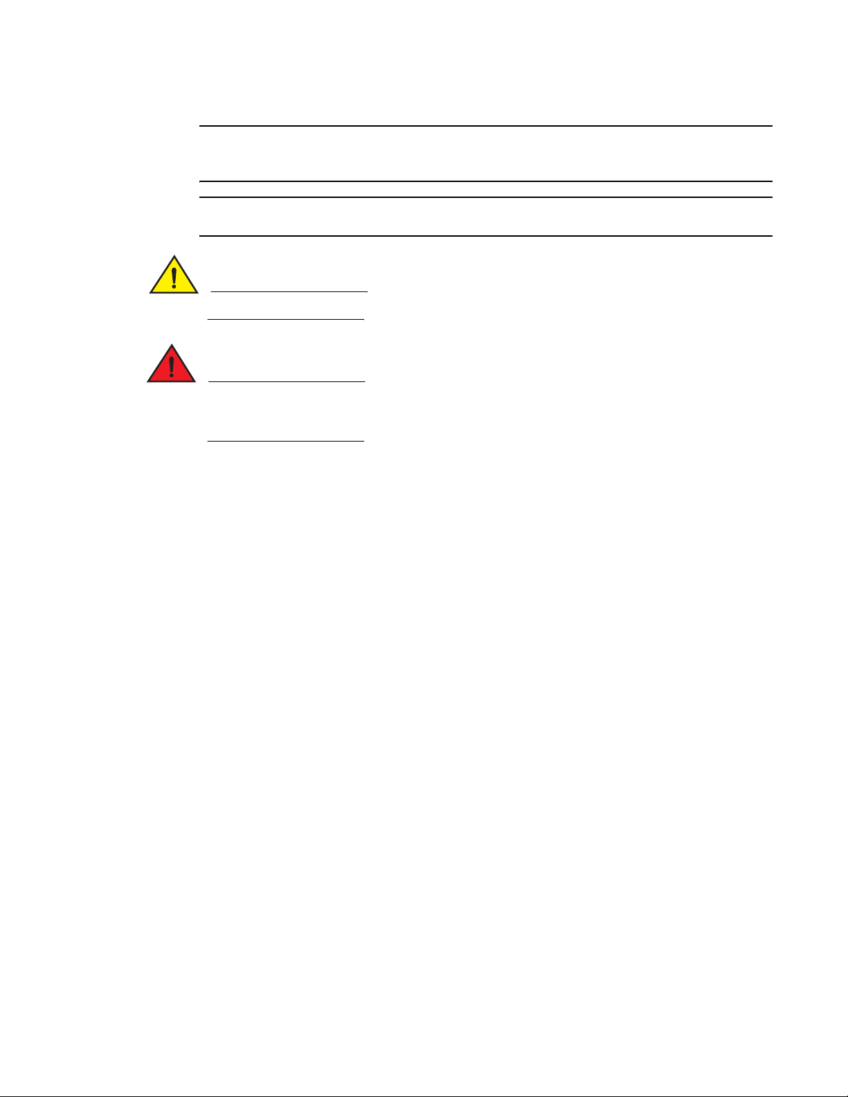
Setting Refresh Frequency for Internet Explorer
Correct operation of Web Tools with Internet Explorer requires specifying the appropriate settings
for browser refresh frequency and process model. Browser pages should be refreshed frequently to
ensure the correct operation of Web Tools.
1. Click Tools > Internet Options in the browser.
2. Click the General tab and click Settings under “Temporary Internet Files.”
3. Click Every visit to the page under “Check for newer versions of stored pages,” as shown in
Figure 1 on page 3.
2 Web Tools Administrator’s Guide
53-1000606-01
Page 23
System requirements
Configure your browser to check
for newer versions of stored pages
every visit to the page.
1
FIGURE 1 Configuring Internet Explorer
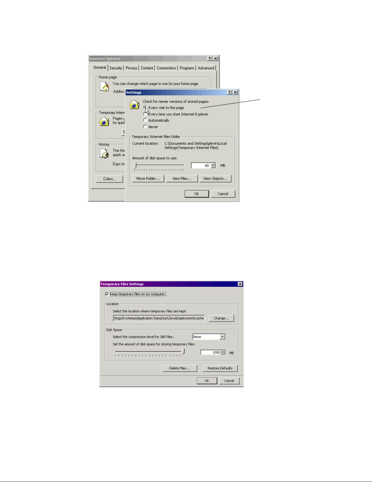
Deleting temporary internet files used by Java applications
For Web Tools so operate correctly, you must delete the temporary internet files used by Java
applications.
1. From the Control Panel, open Java.
2. Click the General tab and click Settings.
FIGURE 2 Temporary Internet Settings dialog box
3. Click the Delete Files button to delete the temporary files used by Java applications.
4. Click OK on the confirmation dialog box.
You can clear the Trace and Log files check box if you want to keep those files.
Web Tools Administrator’s Guide 3
53-1000606-01
Page 24

Installing Java on the workstation
1
5. Click OK.
6. On the Java Control Panel, click the View button to review the files that are in the Java cache.
If you have deleted all the temporary files, the list is empty.
Installing Java on the workstation
Java Plug-in must be installed on the workstation. If you try to open Web Tools without any Java
Plug-in installed:
• Internet Explorer automatically prompts and downloads the proper Java Plug-in.
• Firefox downloads the most recently released Java Plug-in.
If you try to open Web Tools with an earlier version Java Plug-in installed:
• Internet Explorer might prompt for an upgrade, depending on the existing Java Plug-in version.
• Firefox uses the existing Java Plug-in.
Installing the JRE on your Solaris or Linux client workstation
1. Locate the JRE on the Internet, at the following URL:
http://java.sun.com/products/archive/j2se/5.0_06/index.html
NOTE
This URL points to a non-Brocade Web site and is subject to change without notice.
2. Select JRE 5.0 Update 6.
3. Follow the instructions to install the JRE.
4. Create a symbolic link from this location:
$FIREFOX/plugins/libjavaplugin_oji.so
To this location:
$JRE/plugin/$ARCH/ns600/libjavaplugin_oji.so
Installing patches on Solaris
1. Search for any required patches for your current version of the JRE at the following Web site:
http://sunsolve.sun.com/pub-cgi/show.pl?target=patchpage
NOTE
This URL points to a non-Brocade Web site and is subject to change without notice.
2. Follow the link to download the patch, and exit the browser when done.
3. Install the patch and reboot the system.
4 Web Tools Administrator’s Guide
53-1000606-01
Page 25

Installing the Java plug-in on Windows
1. Click Start Menu > Settings > Control Panel and select the Java Plug-in Control Panel.
2. Click the About tab.
3. Determine whether the correct Java Plug-in version is installed:
• If the correct version is installed, Web Tools is ready to use.
• If no Java Plug-in is installed, point the browser to a switch running Fabric OS 5.2.0 or later
to install JRE 1.5.0_06. Web Tools will guide you through the steps to download the proper
Java Plug-in.
• If an outdated version is currently installed, uninstall it, reboot your personal computer,
re-open the browser, and enter the address of a switch running Fabric OS 5.2.0 or later to
install JRE 1.5.0_06. Web Tools will guide you through the steps to download the proper
Java Plug-in.
Configuring the Java plug-in
If you are managing fabrics with more than 10 switches or 1000 ports, or if you are using the iSCSI
Gateway module extensively, you should increase the default heap size to 256 MB to avoid
out-of-memory errors.
Configuring the Java plug-in
1
If you are using a Mozilla family browser (Firefox, Netscape), you should set the default browser in
the Java control panel.
The following procedures instruct you in increasing the default heap size in the Java Control Panel
and in setting the default browser.
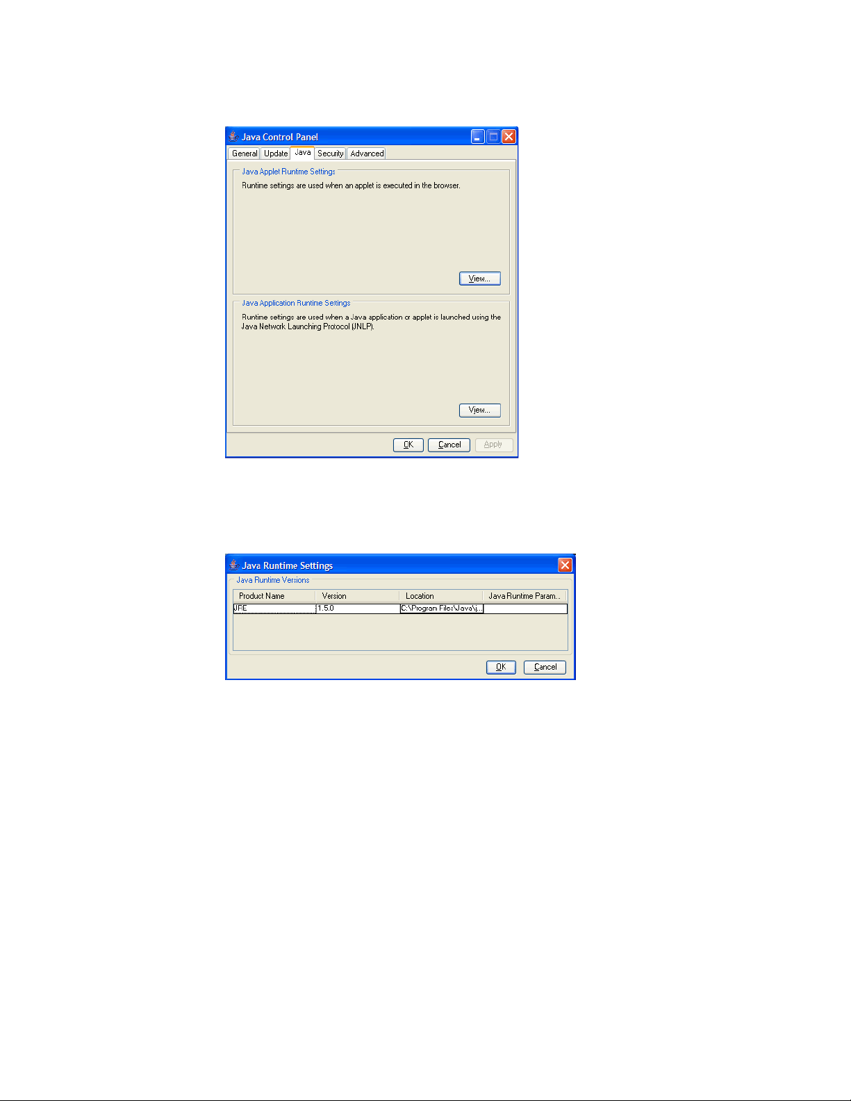
Configuring the Java plug-in for Windows
1. From the Start menu button, select Settings > Control Panel > Java.
2. Click the Java tab.
Web Tools Administrator’s Guide 5
53-1000606-01
Page 26
Configuring the Java plug-in
1
FIGURE 3 Java Control Panel
3. In the section Java Applet Runtime Settings, click View
The Java Runtime Settings dialog box appears.
FIGURE 4 Java Runtime Settings
4. Double-click in the Java Runtime Parameters field and type the following information to set the
minimum and maximum heap size:
-Xms256m -Xmx256m
In this example, the minimum and maximum sizes are both 256 MB.
5. Click Apply to apply your settings and close the Java Control Panel.
Configuring the Java plug-in for Mozilla family browsers
1. From the Start menu button, select Settings > Control Panel
2. Click the Advanced tab and expand the Default Java for browsers option.
6 Web Tools Administrator’s Guide
53-1000606-01
Page 27
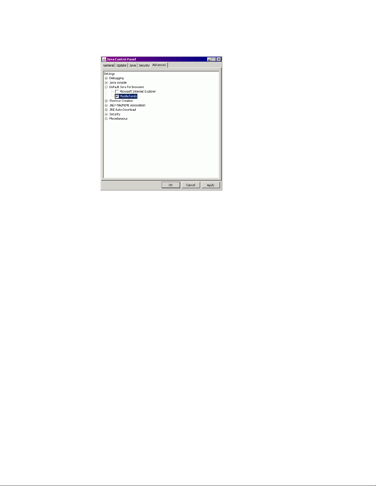
FIGURE 5 Default Java for browsers option
Installing a Web Tools license
1
3. Select Mozilla family and click OK.
4. Click Apply to apply your settings and close the Java Control Panel.
Installing a Web Tools license
You can install a Web Tools license either through telnet or over the Web. License keys are provided
on a per-chassis basis, so for products that support multiple logical switches (domains), a license
key applies to all domains within the chassis.
Use the instructions in “Installing a Web Tools license through telnet” to determine whether a
license is already installed on a switch. If a license is not installed, contact your switch supplier to
obtain a license key.
Installing a Web Tools license through telnet
Use the following procedure to determine whether a Web Tools license is installed on your switch
and, if not, install it.
1. Log in to the switch via telnet (see the Fabric OS Administrator’s Guide for more information),
using an account that has administrative privileges.
2. To determine whether a Web Tools license is already installed on the switch, type licenseShow
on the telnet command line.
Web Tools Administrator’s Guide 7
53-1000606-01
Page 28

Installing a Web Tools license
1
3. On the command line, type the following command:
4. Verify that the license was added by typing the following command:
A list displays all the licenses currently installed on the switch:
switch:admin> licenseshow
1A1AaAaaaAAAA1a:
Zoning license
1A2AaAbbbBBBA1a:
SES license
1A3AaAbcbBBCC1d:
QuickLoop license
]—This is the license key (excluding the colon). The installed feature is listed below.
If the Web Tools license is not included in the list or is incorrect, continue with step 3.
licenseadd key
Where key is the license key value, is case-sensitive, and must be entered exactly as given.
licenseshow
If the Web Tools license is listed, the feature is available. If the license is not listed, repeat
step 3.
Installing a Web Tools license through a Web site
If you open Web Tools from any nonlicensed switch, the software automatically displays the license
dialog box. If the fabric already contains at least one licensed switch, you can use Web Tools to view
and license other switches from the licensed switch.
If you do not have a switch that has a Web Tools license installed on it, Web Tools is active for only
30 days from the date that the switch is activated. After the 30 day period, the Web Tools
functionality is disabled, and error messages appear in the logs and on the console to inform you
that you must have a Web Tools license to access the feature.
1. Open the Web browser and type the IP address of the switch in the Location/Address field:
http://10.77.77.77
2. Press Enter.
If a Web Tools license is already installed on the switch, Web Tools opens. If no license is
installed, a license dialog box appears.
3. If the license dialog box appears, follow the instructions provided.
Installing other licenses through the Web
1. Open the Web browser and type the IP address of the licensed switch in the Location/Address
field:
http://10.77.77.77
2. Press Enter.
3. On Web Tools Switch Explorer, click the switch to which you want to add a license.
4. On the licensing window, follow the instructions that are provided.
8 Web Tools Administrator’s Guide
53-1000606-01
Page 29

Value line licenses
If your fabric includes a switch with a limited switch license and you are opening Web Tools using
that switch, if the fabric exceeds the switch limit indicated in the license, Web Tools allows a 30-day
“grace period” in which you can still monitor the switch through Web Tools. However, Web Tools will
display warning messages periodically.
These messages warn you that your fabric size exceeds the supported switch configuration limit
and tells you how long you have before Web Tools will be disabled. After the 30-day grace period,
you will no longer be able to open Web Tools from the switch with the limited switch license if that
switch is still exceeding the switch limit.
Web Tools is part of the Fabric OS of a switch. When you open Web Tools on a switch, you can
manage other switches in the fabric that have lower or higher firmware versions. It is important to
note that when accessing these switches you are opening the remote switch’s version of Web
Tools, and the functionality available for those switches might vary.
Opening Web Tools
You can open Web Tools on any workstation with a compatible Web browser installed. For a list of
Web browsers compatible with Fabric OS 6.0.0, see Table 1. Web Tools also supports HTTPS
protocol, if that protocol is enabled for the switch. For more information on enabling the HTTPS
protocol on your switch, see the Fabric OS Administrator’s Guide.
Value line licenses
1
1. Open the Web browser and type the IP address of the licensed switch in the Address field:
http://10.77.77.77
or
https://10.77.77.77
2. Press Enter.
A browser window opens to open Web Tools. A Login dialog box opens. See “Logging in” on
page 10 for more information. The browser window is left open. You can close it anytime after
the Login dialog box appears.
What happens next depends on the switch type:
• For the Brocade 200E, 4012, 4016, 4018, 4020, 4024, 4100, 4900, and 5000 switches, one
of the following opens, depending on the switch configuration:
- EZSwitchSetup Switch Manager
This interface opens if the switch has already been set up and is configured with
EZSwitchSetup. See the EZSwitchSetup Administrator’s Guide for information about the
EZSwitchSetup interface.
If you want to use Web Tools instead of EZSwitchSetup, click Advanced Management in the
lower-left corner of the window to open the Web Tools interface.
- Web Tools (see Figure 6 on page 10)
The interface opens if the switch is configured with the command line interface (CLI) or
Web Tools.
Web Tools Administrator’s Guide 9
53-1000606-01
Page 30
Opening Web Tools
1
• For the Brocade AP7420, the Web Tools—AP Edition interface opens. See the Web Tools—AP
Edition Administrator’s Guide for information on using the Web Tools—AP Edition interface for
the Brocade AP7420.
• For all other switches, the Web Tools interface opens.
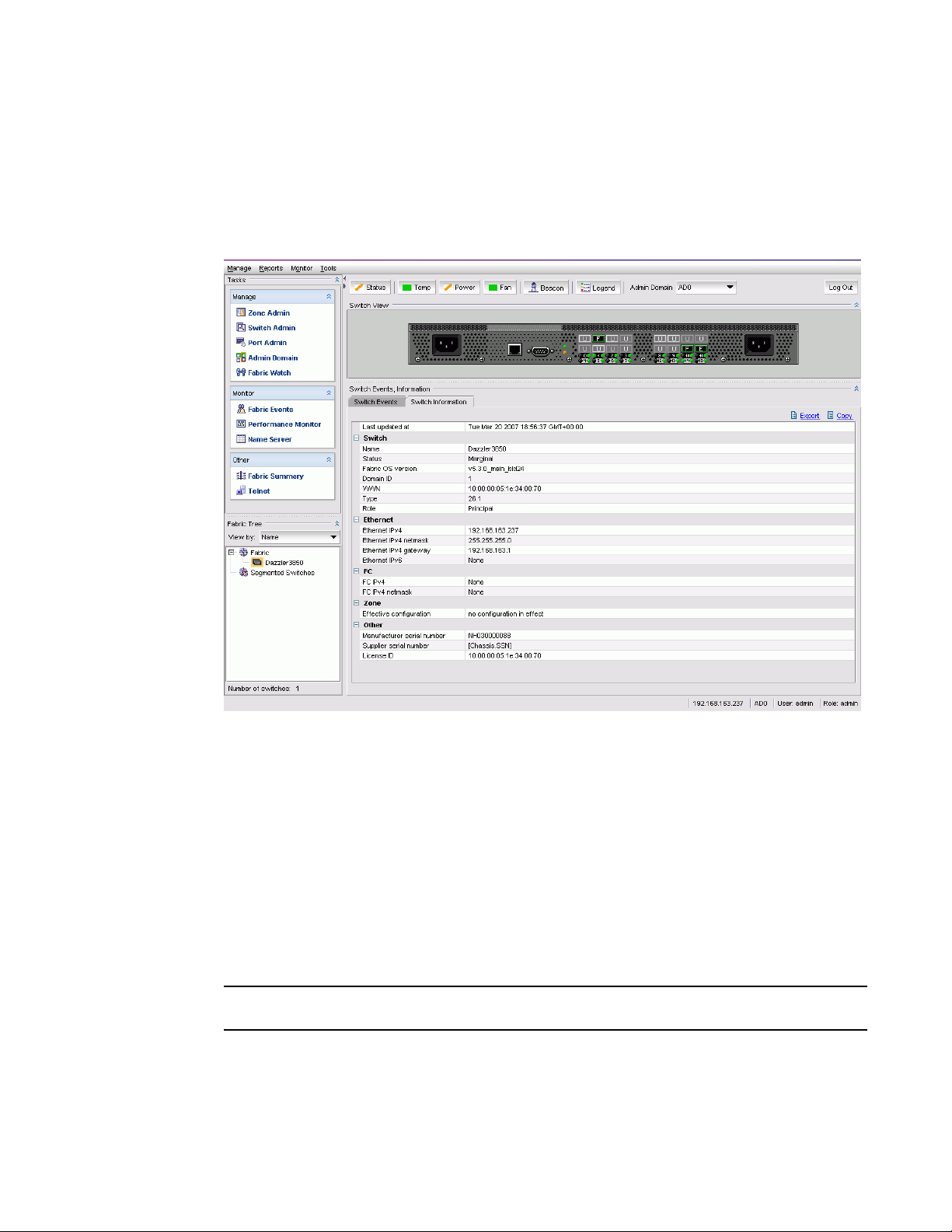
This book describes only the Web Tools interface.
FIGURE 6 Web Tools interface
Logging in
When you use Web Tools, you must log in before you can view or modify any switch information.
This section describes the login process.
Prior to displaying the login window, Web Tools displays a security banner (if one is configured for
your switch), which you must accept before logging in. The security banner displays every time you
access the switch.
When you are presented with the login screen you must provide a user name and a password. Your
home Admin Domain is automatically selected. You can choose to log into an Admin Domain other
than your home domain.
NOTE
You must log in before you can view Switch Explorer (shown in Figure 6 on page 10).
1. Click Run on the signed certificate applet
If you select the check box Always trust content from this publisher, the dialog box is not
displayed when you open Web Tools again.
10 Web Tools Administrator’s Guide
53-1000606-01
Page 31

FIGURE 7 Signed applet certificate
2. Click OK in the security banner window, if one appears.
Opening Web Tools
1
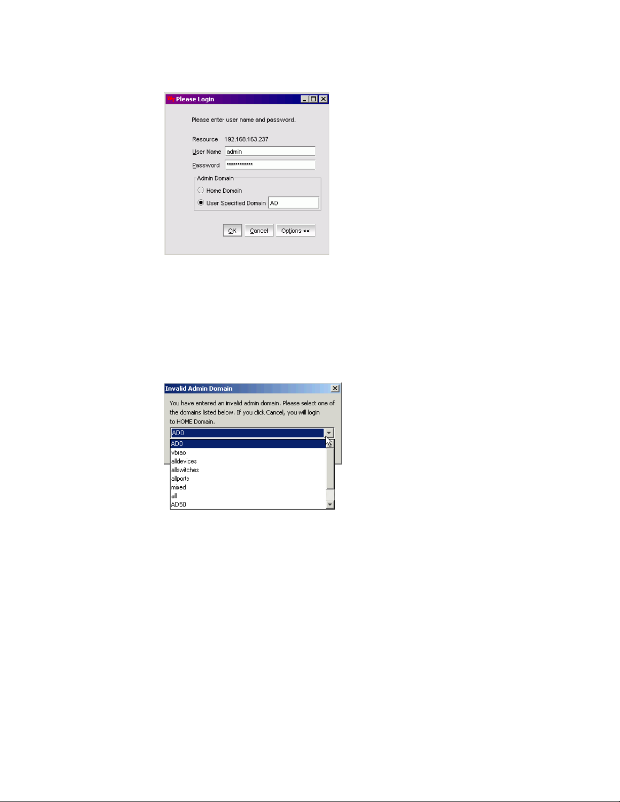
FIGURE 8 Login dialog box
3. On the login dialog box, type your user name.
4. Type the password.
If your current password has expired, you must also provide a new password and confirm the
new password.
Optional: Click Options to select an Admin Domain other than your default home domain.
The Login dialog box displays the Admin Domain options. You do not have an Admin Domain
option if the Access Gateway or Interoperability mode is enabled.
• Click the Home Domain radio button to log in to your default Admin Domain.
• Click the User Specified Domain radio button to log in to another Admin Domain instead of
your home domain. Type the Admin Domain name or number.
Web Tools Administrator’s Guide 11
53-1000606-01
Page 32
Opening Web Tools
1
FIGURE 9 Login dialog box with Admin Domain options
5. Click OK.
If the user name or password is incorrect, a dialog box displays indicating an authentication
failure.
If you entered valid credentials, but specified an invalid Admin Domain, a dialog box displays
from which you can choose a valid Admin Domain or click Cancel to log in to your home
domain.
FIGURE 10 Invalid Admin Domain dialog box
12 Web Tools Administrator’s Guide
53-1000606-01
Page 33

Logging out
You can end a Web Tools session either by logging out or by closing Switch Explorer window.
You might be logged out of a session involuntarily, without explicitly clicking the Logout button,
under the following conditions:
• A physical fabric administrator changes the contents of your currently selected Admin Domain.
• Your currently selected Admin Domain is removed or invalidated.
• Your currently selected Admin Domain is removed from your Admin Domain list.
• You initiate a firmware download from the Web Tools Switch Administration window. In this
case, you are logged out a few minutes later when the switch reboots.
• Your session times out.
Administrative domains
An “administrative domain” (Admin Domain or AD) is a logical grouping of fabric elements that
defines what switches, ports, and devices you can view and modify. An Admin Domain is a filtered
administrative view of the fabric. The logical view presented within an Admin Domain does not hide
fabrics, chassis, switches, and slots; however, the attributes of switch ports and end devices are
filtered based on Admin Domain membership.
Administrative domains
1
Admin Domains permit access to a configured set of users. If a switch is part of an Admin Domain,
then when you log in with an account that has an administrator role, you can perform switch enable
and disable functions and all switch port-level functions such as port enable and port disable. You
cannot perform fabric-wide management, as switch membership within a zone does not provide
zoning rights on the switch ports.
NOTE
Do not confuse an Admin Domain with the domain ID of a switch. They are two different identifiers.
Admin Domains are identified by a numeric ID (0–255) and also by name. This name can be
autogenerated based on the ID (for example AD1 or AD5) or you can specify a more informative
name such as Accounting or Engineering.
AD0 is a special Admin Domain that contains all switches, ports, and devices that have not been
put into other Admin Domains. AD255, another special domain, is an unfiltered view of the entire
physical fabric.
NOTE
Some features work only in AD255 when user-defined domains are present, such as ACL
management.
By default, all fabric elements belong to AD0. In Fabric OS v5.2.0 and higher, a physical fabric
administrator with appropriate permissions can create up to 254 additional Admin Domains and
assign fabric resources to them (see Chapter 7, “Managing Administrative Domains”). Only users
who have been specifically assigned to those domains can view and modify the resources they
contain.
Web Tools Administrator’s Guide 13
53-1000606-01
Page 34

Administrative domains
1
Admin Domains and login
You are always logged in to an Admin Domain, and you can view and modify only the devices in that
Admin Domain.
You can log in to only one Admin Domain at a time. When you log in, you select the Admin Domain
that you want to manage. You can later change the Admin Domain to which you are logged in.
If you have more than one Admin Domain, one of them will have been specified as your “home
Admin Domain.” Your home Admin Domain is the one you are automatically logged in to unless you
explicitly select a different one. If a home Admin Domain is deleted or deactivated, then by default
you will be logged in to the lowest numbered Admin Domain in your Admin Domain list. A home
Admin Domain, like the Admin Domain list, is a configurable property of a non-default user account.
For default accounts such as admin and user, the home Admin Domain defaults to AD0 and cannot
be changed. For user-defined accounts, the home Admin Domain also defaults to 0 but an
administrator can set the home Admin Domain to any Admin Domain to which the account has
been given access. The Admin Domain list for default admin accounts is 0–255, which gives
automatic access to any Admin Domain as soon as it is created, and makes them physical fabric
administrators. The Admin Domain list for the default user account is AD0 only. The Admin Domain
list property for default accounts also cannot be changed.
A “physical fabric administrator” is an admin role user whose account has access to all Admin
Domains (AD0-255) as soon as they are created. Only physical fabric administrators can create,
modify, delete, and activate or deactivate Admin Domains.
Admin Domains and switch WWN
Admin Domains are treated as fabrics. Because switches cannot belong to more than one fabric,
switch WWNs (world-wide names) are converted so that they appear as unique entities in different
Admin Domains (fabrics).
The switch WWN is in the following format:
10:00:nn:nn:nn:nn:nn:nn
In an Admin Domain context, the switch WWN is converted from NAA=1 to NAA=5 format, with the
Admin Domain number added, using the following syntax:
5n:nn:nn:nn:nn:nn:n9:xx
where xx is the AdminDomain_number.
For example, if the switch WWN is:
10:00:00:60:69:e4:24:e0
then the converted WWN for that switch in AD1 is:
50:06:06:9e:42:4e:09:01
Admin Domains and zoning
Each Admin Domain has its own zone database, with both defined and effective zone
configurations and all related zone objects (zones, zone aliases, and zone members). Within an
Admin Domain, you can configure zoning only with the devices that are present in that Admin
Domain.
14 Web Tools Administrator’s Guide
53-1000606-01
Page 35

Before you implement Admin Domains, you must set the default zoning mode. See “Enabling
administrative domains” on page 83 for additional information.
You cannot perform any zoning operations from AD255.
Role-Based Access Control
Role-Based Access Control (RBAC) defines the capabilities that a user account has based on the
role the account has been assigned. For each role, there is a set of pre-defined permissions on the
jobs and tasks that can be performed on a fabric and its associated fabric elements.
When you log in to a switch, your user account is associated with a pre-defined role. The role that
your account is associated with determines the level of access you have on that switch and in the
fabric. Following is a description of each of the roles:
admin You have full access to all of the Web Tools features.
operator You can perform any actions on the switch that do not affect the stored configuration.
securityadmin You can perform actions that do not affect the stored configuration.
switchadmin You can perform all actions on the switch, except the following:
• You cannot modify zoning configurations.
• You cannot create new accounts.
• You cannot view or change account information for any accounts. You can only view
zoneadmin You can only create and modify zones.
fabricadmin You can do everything the Admin role can do except create new users.
basicswitchadmin You have a subset of Admin level access.
user You have nonadministrative access and can perform tasks such as monitoring system
activity.
Role-Based Access Control
your own account and change your account password.
1
For information about changing user account roles, see “Creating and maintaining user-defined
accounts” on page 209.
Session management
A Web Tools session is the connection between the Web Tools client and its managed switch. A
session is established when you log in to a switch through Web Tools. When you close Switch
Explorer, Web Tools ends the session.
A session remains in effect until one of the following happens:
• You log out
• You close the Switch Explorer window
• The session ends due to inactivity (time out)
A session automatically ends if there has been no information sent to the switch for more than two
hours. Because user key strokes are not sent to the switch until you apply or save the information,
it is possible for your session to end while you are entering information in the interface. For
example, entering a zoning scheme in the Zoning module does not require you to send information
to the switch until you save the scheme.
Web Tools Administrator’s Guide 15
53-1000606-01
Page 36

Requirements for IPv6 support
1
Web Tools does not display a warning when the session is about to time out. If your session ends
due to inactivity, all Web Tools windows become invalid and you must restart Web Tools and log in
again.
Web Tools enables sessions to both secure and nonsecure switches.
Access rights for your session are determined by your role-based access rights and by the contents
of your selected Admin Domain. After you log in, you can change to a different Admin Domain at any
time; however, you cannot change your role-based permissions.
Ending a Web Tools session
To end a Web Tools session, perform one of the following actions:
• Click Logout in Switch Explorer.
• Click the X in the upper-right corner of Switch Explorer window to close it.
• Close all open Web Tools windows.
NOTE
If you click the Logout button in Switch Explorer, and Web Tools leaves the Temperature, Fan, Power,
or Fabric Event windows open, you must manually close them.
Requirements for IPv6 support
The following list provides requirements for Web Tools IPv6 support:
• In pure IPv6 environment, you must configure DNS maps to IPv6 address of the switch.
• The switch name is required to match DNS name that is mapped to IPv6 address.
• If both IPv4 and IPv6 addresses have been configured, Web Tools uses the IPv4 address to
launch the switch.
• Use a switch that has v5.3.0 or later release firmware to manage a mixed fabric of IPv4 and
IPv6 switches.
• Switches running on version 5.2.0 do not discover IPv6 address-only switches in the same
fabric, until the IPv4 address has been configured.
• An IPv6 address cannot be used to directly launch a switch from a Windows environment; it
can be used in Unix and Linux environment.
• The FCIP wizard does not support IPv6. If IPv6 interfaces, routes, and tunnels are configured
on the switch, the wizard displays them, but does not allow the user to modify them.
16 Web Tools Administrator’s Guide
53-1000606-01
Page 37

Chapter
Using the Web Tools Interface
In this chapter
This chapter contains the following information:
•Viewing Switch Explorer . . . . . . . . . . . . . . . . . . . . . . . . . . . . . . . . . . . . . . . . . 17
•Displaying tool tips. . . . . . . . . . . . . . . . . . . . . . . . . . . . . . . . . . . . . . . . . . . . . . 22
•Refresh rates . . . . . . . . . . . . . . . . . . . . . . . . . . . . . . . . . . . . . . . . . . . . . . . . . . 24
•Displaying switches in the fabric . . . . . . . . . . . . . . . . . . . . . . . . . . . . . . . . . . 25
•Working with Web Tools: recommendations . . . . . . . . . . . . . . . . . . . . . . . . . 25
Viewing Switch Explorer
The first thing you see when you log in to a switch with Web Tools is Switch Explorer, shown in
Figure 11 on page 18. Switch Explorer is divided into areas that provide access to, and information
about, the switch and fabric:
2
• The Left Pane provides Tasks and Fabric Tree areas.
The Tasks area lets you perform management, monitoring, and other tasks. The Fabric Tree
displays a list of all the switches in the fabric.
• A menu bar, at the top of the window, provides access to commands and actions. The menu
bar displays the same commands as the left pane of Switch Explorer. If you choose to collapse
the left pane, you still have access to:
• Management tasks, such as zone administration, switch administration, and port
administration.
• Reporting tasks, such as viewing a fabric summary or the status of a switch
• Monitoring tasks, such as viewing fabric events, performance monitoring, and viewing the
temperature or power status.
• Tools tasks, such as opening the telnet window.
• Switch View buttons above Switch View provides access to switch information: status,
temperature, power, and fan data, beaconing, and the legend for the Switch View.
Although clicking a button can open a separate dialog or window which you can perform
management tasks, all access control is established when you first log in to the switch.
Buttons in Switch Explorer are unavailable for two reasons: your account does not have
sufficient privileges to access this feature, or your currently selected Admin Domain does not
meet some condition to access the feature.
• Changing the Admin Domain context is a drop-down field which indicates the administrative
domain you are viewing and allows you to change it.
• Switch View displays an interactive graphic of the switch.
Web Tools Administrator’s Guide 17
53-1000606-01
Page 38

Viewing Switch Explorer
2
• Switch Events and Switch Information are tabs that allow you to view event information and
switch information, including connectivity, port, zone and other information.
• An indicator bar in the lower-right corner of every module window contains the Admin Domain
you are currently in, the user name with which you logged in to the switch, and the role
associated with your user account.
Use this table with Figure 11 to identify the areas of Switch Explorer.
1 Tasks and Fabric Tree
2Menu bar
3 Switch View buttons
4 Changing the Admin Domain context
5 Switch View
6 Switch Events and Switch Information
7Indicator bar
2
1
FIGURE 11 Switch Explorer
3
4
5
6
7
18 Web Tools Administrator’s Guide
53-1000606-01
Page 39

Viewing Switch Explorer
Tasks
The Tasks menu lets you manage, monitor, and perform other tasks.
Management section provides access to:
• Zone administration
Zone information is collected from the selected switch. The icon is displayed only if a Brocade
Advanced Zoning license is installed on the switch. If an ACL-based FCS policy is in effect,
zoning can be administered only from the primary fabric configuration server (FCS) switch. If
the selected switch has a zoning license installed but is not the primary switch, the Zone
Admin icon is displayed but not activated. See “Managing zoning with Web Tools” on page 97
for more information.
• Switch administration
• Port administration
• Admin Domain administration
• Fabric Watch
NOTE
Some of these functions require a license key to activate them.
2
Monitor section provides access to
• Fabric events
Fabric events information is collected from the launch switch. See “Monitoring events” on
page 44 for more information.
• Performance monitoring
• Name Server information
Name Server information is collected from the selected switch. See “Displaying the Name
Server entries” on page 49 for more information.
Other section provides access to:
• Fabric summary
Fabric summary information is collected from the selected switch. See “Displaying a fabric
summary report” on page 48 for more information.
• Telnet tools
NOTE
It is important to note that certain Fabric OS features are available only on particular switch types,
and the system displays only the icons that are appropriate for the switch type.
Fabric Tree
Fabric Tree displays all switches in the fabric, even those that do not have a Web Tools license and
that are not owned by your selected Admin Domain. Switches that are not owned by the Admin
Domain are shown in the Fabric Tree with switch status. Fabric Tree does not display switches
segmented before Web Tools was opened.
Web Tools Administrator’s Guide 19
53-1000606-01
Page 40

Viewing Switch Explorer
2
Use the drop-down menu at the top of the Fabric Tree area to view switches in the Fabric Tree by
switch name, IP address, or WWN. The background color of the switch icon indicates the current
status of the switch. You can hover the cursor over a switch to display the IP address and current
status. To manually refresh the status of a switch within the fabric, right-click the switch in the
Fabric Tree and choose Refresh.
Although Fabric Tree displays all the switches in the fabric, you can manage only the switches that
have a Web Tools license installed. Other switches must be managed through the Fabric OS
command line interface (CLI) or another management application. For information on adding a
Web Tools license to a switch, see “Installing a Web Tools license” on page 7.
Changing the Admin Domain context
The Admin Domain field displays the currently selected Admin Domain and allows you to change to
a different one. All the Admin Domains assigned to you are available in the drop-down menu.
For most administrative tasks you must be in either AD0 or the physical fabric. The following
procedure describes how to change the Admin Domain. This action is referred to as “changing the
Admin Domain context.”
1. Select an Admin Domain from the Admin Domain drop-down menu.
FIGURE 12 Changing the Admin Domain
2. Click OK in the confirmation window.
Switch Explorer refreshes to display the new Admin Domain context. You can monitor progress
using the progress bar.
If there are other windows open, the system displays a list of the open windows. You can
choose to change the Admin Domain which will close all the open windows, or cancel the
action and return to Switch Explorer.
NOTE
The Telnet window, the Fabric Details, and Fabric Events windows are not AD-filtered and do
not need to be closed.
20 Web Tools Administrator’s Guide
53-1000606-01
Page 41

Viewing Switch Explorer
2
Switch View buttons
The Switch View buttons let you access the following switch information:
• Status - click the button to view the status of the switch.
• Temperature - click the button to view temperature monitors.
• Power - click the button to view power supply information.
• Fan - click the button to view the status of the switch fans.
• Beaconing.
• Legend - click the button to view the legend for the Switch View.
NOTE
For all status displays based on errors per time interval, any errors cause the status to show
faulty until the entire sample interval has passed.
Switch View
The Switch View displays a graphical representation of the selected switch, including a real-time
view of switch and port status. Select a switch in the Fabric Tree to access the Switch View for that
switch. Figure 13 shows an example of a Switch View.
FIGURE 13 Example of a Switch View
Port representations
The ports in the Switch View show the port type. Borders around the accessible ports indicate that
SFP modules are present. A colored border indicates the status of the port; for example, a green
border indicates that the port is connected and traffic is flowing. For example, in Figure 13, port 20
has a border, 21 does not have a border, and 22 has a colored border. Ports that are not accessible
do not display the port type and do not have borders.
The port LEDs in the Switch View match the LEDs on the physical switch; however, the blink rate of
the LEDs in the Switch View does not necessarily match the blink rate of the LEDs on the physical
switch. See “Interpreting port LEDs” on page 150 for more information. Ethernet ports have 2
LEDs.
Right-click a port in Switch View to get a menu from which you can open the Port Administration
window and view detailed information about the port. From Port Administration, you can access
information on all other ports. See Chapter 5, “Managing Your Ports” for more information.
Web Tools Administrator’s Guide 21
53-1000606-01
Page 42

Displaying tool tips
2
If the selected Admin Domain does not include ownership of some ports that are physically present
on the switch, these ports are represented as black rectangles with horizontal gray bars indicating
they are not accessible. E_Ports are visible in all domains. You cannot open the Port Administration
window by clicking these ports. In Figure 13, only ports 16 through 31 (and not the switch) are
owned by the current Admin Domain, as shown in the figure:
• E_Ports 0, 1, 14, 24, and 25 are shown as online and accessible.
• All other ports in the range from 0 through 15 are shown as inaccessible, with no type
information displayed. If you click the E_Ports in this range, the Port Management module
opens in read-only mode.
• Ports in the range from 16 through 31 are both accessible and controllable. When these ports
(including E_Ports) are clicked, the Port Administration window opens.
NOTE
For the Brocade DCX Director, the Switch View displays the USB and ISL ports and lets you launch
the appropriate applications for them.
Switch View refresh rates
The Switch View display is refreshed at 15 second intervals. However, the initial display of Switch
Explorer might take from 30 to 60 seconds after the switch is booted. Refresh rates are fabric-size
dependent. The larger the fabric, the longer it takes to poll the fabric and refresh the view. F_Port
and L_Port connection changes refresh immediately.
Autorefresh intervals may be not be exactly 15 seconds. The refresh rate varies depending on the
activity in the fabric and on the host system you are using.
Switch Events and Switch Information
Switch Events and Switch Information appear as tab forms under Switch View.
Switch Information View displays switch information such as switch name, status, Fabric OS
version, domain ID, IP address, WWN, and current zone configuration. The information in the
Switch Information View is polled every 60 seconds.
For more information, see “Displaying switch information” on page 146.
Displaying tool tips
If you hover the cursor over most components, the system displays tool tip information about the
component. Figure 14 shows several examples of tool tips.
In Fabric Tree you can hover over a switch to view its type, Ethernet IP, Fibre Channel IP, and status
of the switch.
In Switch View, you can hover over a blade to view the blade ID and its status. It is easier to use the
top of the blade to display the tool tip so that you do not inadvertently display the port tool tips.
When you hover over a port, you can view the port number, port index, port type (E, F, L, or U_Port),
port status (online or offline), and port state (in-sync, no_sync, no light, or no module). If you
right-click the port, the system displays the tool tip information as well as the port world-wide name.
For example, Figure 14 displays the mouseover tool tip for port 19 and the right-click tool tip for
port 30.
22 Web Tools Administrator’s Guide
53-1000606-01
Page 43

Displaying tool tips
When you hover over the Web Tools buttons, the system displays a brief description of the button.
2
FIGURE 14 Mouseover view of switch information
You can right-click a port to quickly perform some basic port administration tasks, as shown in
Figure 15.
FIGURE 15 Right-click menu for ports (from Switch Explorer)
Web Tools Administrator’s Guide 23
53-1000606-01
Page 44

Refresh rates
2
Refresh rates
• The Port Admin option opens the Port Administration window
• The Port Details option displays read-only information about a port, without opening the Port
Administration window. You can export and copy the information from the Port Details window.
• The Configure option provides another menu of options to allow you to rename, enable, disable
ports, and set persistent enable/disable without opening the Port Administration window.
Different panels of Web Tools refresh at different rates.
The refresh, or polling, rates listed in this section and throughout the book indicate the time
between the end of one polling and the start of the next, and not how often the screen is refreshed.
A refresh rate of 15 seconds does not ensure that a refresh occurs every 15 seconds. It ensures
that the time between each refresh activity is no more than 15 seconds.
Autorefresh intervals might be not be exactly 15 seconds. The refresh rate varies depending on the
activity in the fabric and on the host system you are using. Following are some variables you should
consider when refreshing the fabric:
• Retrieval time increases when you are in a large fabric as there is more data to fetch from the
switch(s).
• Processor speed of the system you are using may slow down the refresh rate.
• OS-Job Scheduling if you are using a host-system in the data center impacts the refresh rate.
• JVM-Performance can contribute to causing interval differences between what is on-screen
and how long it is actually taking.
For these reasons, the time displayed in the port statistics tab might not be refreshed as expected.
The counter time indicates only that “this statistics data is retrieved from the switch in this time.”
To ensure the correct information, the time field is updated along with the port statistics data after
every refresh.
The refresh rates are different for each module. Table 3 lists polling rates by module. Though these
rates are sample rates, they correctly illustrate variance in the refresh rates throughout Web Tools.
TABLE 3 Polling rates
Module Polling Rate
Name Server User-defined; 15 sec minimum
Zoning Database 60 sec
Fabric Watch 15 sec
Performance Monitor 30 sec
Port Management 60 sec
FC Routing 30–90 sec, depending on network traffic
24 Web Tools Administrator’s Guide
53-1000606-01
Page 45

Displaying switches in the fabric
If your fabric has more than one switch, you can open Web Tools from one switch and then access
other switches.
If you open switches running Fabric OS v4.4.x or higher from a fabric tree displayed for a pre-v4.4.x
switch, some features might be disabled.
1. Open Web Tools as described in “Opening Web Tools” on page 9 and log in to the switch.
Switch Explorer is displayed for the switch you logged in to.
2. If the Fabric Tree is not expanded, click the plus sign (+) in the Fabric Tree to view all the
switches in the fabric.
3. Click a switch in the Fabric Tree.
A separate browser window opens and displays the selected switch. (If the launch switch is
running a Fabric OS version earlier than v5.0.1, the selected switch displays in the same
browser window.)
The graphic of the selected switch is displayed in Switch View. Additional switch information is
displayed in the Switch Events and Switch Information.
Displaying switches in the fabric
2
Working with Web Tools: recommendations
This section lists recommendations for working with Web Tools:
• If you receive an error when saving changes in the Switch Administration window, note the
error messages, refresh the window, and make your changes again. Do not continue making
changes without refreshing the window and determining which changes were saved correctly.
• In a mixed fabric—that is a fabric containing switches and directors running v5.x, v4.x, v3.x, and
v2.x firmware—use the most advanced switches or directors to control the fabric. For example,
use the v5.2.0 switches or directors as the primary FCS, the location to perform zoning tasks,
and the time server (CLI). You should use the most recently released firmware on your
switches.
• If switches are accessed simultaneously from different connections (for example, Web Tools,
CLI, and API), changes from one connection might not be updated to the other, and some
modifications might be lost. Make sure that, when you connect with simultaneous multiple
connections, you do not overwrite the work of another connection.
• Several tasks in Web Tools make fabric-level changes: for example, the tasks in Zone
Administration. When executing fabric-level configuration tasks, wait until you have received
confirmation that the changes are implemented before executing any subsequent tasks. For a
large fabric, this can be up to a few minutes.
• Some data collection and processing operations in the iSCSI Gateway module might take a
long time to complete, especially in large fabrics or fabrics with large numbers of Discovery
Domains and Discovery Domain Sets defined. In most cases, progress bars are provided. Allow
the application a sufficient amount of time (30-40 seconds) to collect and display data before
taking any action or assuming the application is “hanging.”
• A maximum of five simultaneous HTTP sessions to any one switch is recommended. An HTTP
session is considered a Fabric Manager or Web Tools connection to the switch.
Web Tools Administrator’s Guide 25
53-1000606-01
Page 46

Working with Web Tools: recommendations
2
26 Web Tools Administrator’s Guide
53-1000606-01
Page 47

Chapter
Managing Fabrics and Switches
In this chapter
This chapter contains the following sections:
•Managing fabrics and switches using Web Tools . . . . . . . . . . . . . . . . . . . . . 27
•Opening the telnet window . . . . . . . . . . . . . . . . . . . . . . . . . . . . . . . . . . . . . . . 29
•Configuring IP and netmask information . . . . . . . . . . . . . . . . . . . . . . . . . . . . 30
•Configuring a syslog IP address . . . . . . . . . . . . . . . . . . . . . . . . . . . . . . . . . . . 31
•Managing blades . . . . . . . . . . . . . . . . . . . . . . . . . . . . . . . . . . . . . . . . . . . . . . . 32
•Configuring a switch . . . . . . . . . . . . . . . . . . . . . . . . . . . . . . . . . . . . . . . . . . . . 34
•Rebooting the switch. . . . . . . . . . . . . . . . . . . . . . . . . . . . . . . . . . . . . . . . . . . . 36
•Changing system configuration parameters . . . . . . . . . . . . . . . . . . . . . . . . . 36
•Managing licensed features . . . . . . . . . . . . . . . . . . . . . . . . . . . . . . . . . . . . . . 40
•Administering High Availability . . . . . . . . . . . . . . . . . . . . . . . . . . . . . . . . . . . . 41
•Monitoring events . . . . . . . . . . . . . . . . . . . . . . . . . . . . . . . . . . . . . . . . . . . . . . 44
•Displaying a fabric summary report . . . . . . . . . . . . . . . . . . . . . . . . . . . . . . . . 48
•Displaying the Name Server entries. . . . . . . . . . . . . . . . . . . . . . . . . . . . . . . . 49
•Physically locating a switch using beaconing . . . . . . . . . . . . . . . . . . . . . . . . 51
3
Managing fabrics and switches using Web Tools
You can perform most of the management tasks described in this chapter through the Switch
Administration window. Information in the Switch Administration window is retrieved from the
selected switch.
If the switch is not a member of the selected Admin Domain, most tabs in the Switch
Administration window display in read-only mode, regardless of what permission level you have.
The User tab is editable because most of the information on it does not require switch membership
in the current Admin Domain.
Web Tools Administrator’s Guide 27
53-1000606-01
Page 48

Managing fabrics and switches using Web Tools
3
FIGURE 16 Switch Administration window, Switch tab
With the exception of switch time, information displayed in the Switch Administration window is not
updated automatically by Web Tools. To update the information displayed in the Switch
Administration window, see “Refreshing the Switch Administration window” on page 29.
ATTENTION
Most changes you make in the Switch Administration window are buffered, and are not applied to
the switch until you save the changes. If you close the Switch Administration window without saving
your changes, your changes are lost. To save the buffered changes you make in the Switch
Administration window to the switch, click Apply before closing the module or before switching to
another tab. The License tab and the Security Policies tab are exceptions. The changes you make
on these tabs are applied immediately and there is no Apply button.
Some of the management tasks for the Brocade 48000 and Brocade DCX Director are performed
through the High Availability window. This module and the associated tasks are described in
“Administering High Availability” on page 41.
You can also use telnet commands to perform management tasks. See “Opening the telnet
window” on page 29 for information on how to launch a telnet window using Web Tools.
The remainder of this section describes basic Switch Administration window procedures that are
useful for many switch management operations.
28 Web Tools Administrator’s Guide
53-1000606-01
Page 49

Opening the telnet window
3
Opening the Switch Administration window
Most of the management procedures in this chapter are performed from the Switch Administration
window.
1. Select a switch in Fabric Tree.
The switch is displayed in Switch View.
2. Click Switch Admin in the Manage section of the Task s menu.
The Switch Administration window opens in basic mode, as shown in Figure 16 on page 28.
The basic mode displays the “basic” tabs and options.
3. To see all the tabs and options, click the Show Advanced Mode button.
Refreshing the Switch Administration window
You can refresh the fabric element information displayed at any time using the following procedure.
Note that when you click a different tab in the Switch Administration window, the information in the
newly selected tab is automatically refreshed.
1. Click the Refresh button on any tabbed page of the Switch Administration window.
Opening the telnet window
When you open a telnet window, the connection is to the IP interface of the switch. For each switch,
you must open a telnet window.
You cannot connect to CP blades that do not have separate IP addresses. Also, you cannot connect
using Web Tools to a CP blade on a director switch even when the blade has an IP address and
supports telnet sessions. See the Fabric OS Command Reference for information about the telnet
commands.
NOTE
Internet Explorer 7.0 default settings disable telnet functionality. If you are using Internet Explorer
7.0, you must make the appropriate changes in the registry to open the telnet window.
1. Select a switch in Fabric Tree.
You are prompted to log in if the OS is version 5.3.0 or greater. Otherwise, the selected switch
appears in the Switch View.
2. Click the Tel net button in the Other section of the Tas ks menu.
Web Tools opens two windows: the Telne t window and another HTML-based window which is
used to launch the Telnet window. Click OK to close the HTML-based window. The Teln et
window remains open.
3. In the telnet window, enter your user credentials at the login prompt.
4. To close the session, type exit at the prompt.
Web Tools Administrator’s Guide 29
53-1000606-01
Page 50

Configuring IP and netmask information
3
Configuring IP and netmask information
When you configure IP and netmask information for the Brocade 48000 and Brocade DCX Director,
you must configure IP and subnet mask information individually.
When you change the Ethernet IP, subnet mask, gateway IP, or Fibre Channel IP and subnet mask
from Web Tools, there is a normal loss of network connection to the switch. If the IP properties have
changed, you must close all current windows and restart Web Tools with the new IP address.
1. Open the Switch Administration window as described on page 29.
2. Click the Network tab.
FIGURE 17 Network tab
3. In the appropriate IP address section, enter an IP address (for example, 10.77.77.77).
Use the IPv4 Address section and/or the IPv6 Address section to specify IP addresses.
4. For the Brocade 48000 directors only:
In the Advanced Configuration area, type valid IP addresses for the Ethernet IP and subnet
mask for CP0 and CP1.
If the Advanced Configuration area is not visible, click the expand arrows on the right, to
expand the area.
5. Click Apply.
6. Click Close to exit, and then restart Web Tools to continue working.
30 Web Tools Administrator’s Guide
53-1000606-01
Page 51

Configuring a syslog IP address
The syslog IP represents the IP address of the server that is running the syslog process. The syslog
daemon reads and forwards system messages to the appropriate log files and/or users, depending
on the system configuration. When one or more IP addresses are configured, the switch forwards
all error log entries to the syslog on the specified servers. Up to six servers are supported. See
Fabric OS Administrator’s Guide for more information on configuring the syslog daemon.
1. Open the Switch Administration window as described on page 29.
2. Click the Network tab (see Figure 17).
3. In the New IP field, enter an IP address in either IPv4 or IPv6 format, or enter a DNS name.
4. Click Add.
The new IP address is displayed in the Syslog IP area.
5. Click Apply.
Removing a syslog IP address
Configuring a syslog IP address
3
1. Open the Switch Administration window as described on page 29.
2. Click the Network tab.
3. Select a syslog IP in the table and click Remove.
You can click Clear All to remove all of the syslog IP addresses from the table.
4. Click Apply.
Setting Up IP Filtering
Web Tools provides the ability to control what client IP addresses may connect to a switch or fabric.
1. Open the Switch Administration window as described on page 29.
2. Click the Security Policies tab.
3. Click IPFilter on the Security Policies menu.
4. Click Create Policy.
The Create IP Filter Policy window opens.
5. Enter a policy name, choose a policy type, and then click the Add Rule button.
6. Enter the rule order and source IP address, and modify the service/destination port, protocol,
and action as necessary.
7. C li c k OK.
After you create a policy, you can use the controls on this tab to manage the policies:
• The Edit Policy button lets you select an existing policy and make changes to it.
• The Show Policy button lets you view the details of the policy in a read-only window.
• The Delete Policy button lets you delete a policy.
Web Tools Administrator’s Guide 31
53-1000606-01
Page 52

Managing blades
3
• The Clone Policy button lets you copy a policy. Use this feature when you want to create
• The Activate Policy button lets you make an existing policy active.
• The Distribute Policy button lets you distribute a policy to various switches.
• The Accepts Distribution check box lets you set the policy to accept or reject distributions.
Managing blades
Web Tools provides the ability to enable and disable blades, and to set slot-level IP addresses for
blades. The procedure in this section applies only to the Brocade 48000 and Brocade DCX Director.
Enabling or disabling a blade
1. Open the Switch Administration window as described on page 29.
2. Click the Blade tab.
The Firmware Version columns display the firmware loaded onto each blade. A blade can have
more than one firmware image loaded onto it.
similar policies. After you create a clone, you can edit the policy to make the appropriate
changes.
The Enable Blade column in the Blade tab pane indicates whether the blade is enabled.
FIGURE 18 Blade tab
3. Select the Enable Blade check box for each blade you want to enable. Clear the check box to
disable the blade. You cannot enable or disable the CP blades.
32 Web Tools Administrator’s Guide
53-1000606-01
Page 53

4. Click Apply.
Setting a slot-level IP address
1. Open the Switch Administration window as described on page 29.
2. Click the Blade tab.
3. Click the Set IP address button.
Managing blades
3
FIGURE 19 Set IP Address dialog box
4. Select a slot number from the drop-down list.
5. Enter the IP address, subnet mask, and Gateway IP address.
6. Select a type from the drop-down list.
7. C li c k Add to add the new entry to the table.
When you click the Add button, the values remain in the fields.
8. To delete a configuration, select a row in the table and click the Delete button.
NOTE
Clicking the Add or Delete buttons update the table in the Set IP Address dialog box, but does
not send values to the switch.
9. Click the Apply button to save the values currently shown in the table to the switch or click
Cancel to close the dialog box without saving any of your changes.
To update the switch with your changes, you must update the table using the Add and Delete
buttons, and then click Apply.
Viewing IP addresses
If you want to view the IP addresses configured on the switch for the currently populated slots, use
the Show IP Address button.
Web Tools Administrator’s Guide 33
53-1000606-01
Page 54

Configuring a switch
3
1. Open the Switch Administration window as described on page 29.
2. Click the Blade tab.
3. Click the Show IP Address button.
FIGURE 20 Show IP Address dialog box
4. Scroll through the list to view all the information.
5. When you are done, click Close.
Configuring a switch
Use the Switch tab of the Switch Administration window to perform basic switch configuration.
Figure 16 on page 28 shows an example of the Switch tab.
Enabling and disabling a switch
You can identify if a switch is enabled or disabled in the Switch Administration window by looking at
the lower-right corner: the icon means that the switch is enabled, and the icon means that
the switch is disabled. If you hover the cursor over the icon, the system displays text that indicates
the status of the switch.
1. Open the Switch Administration window as described on page 29.
2. Click the Switch tab.
3. In the Switch Status section, click the Enable radio button to enable the switch or click the
Disable radio button to disable the switch.
4. Click Apply.
The system displays a confirmation window that asks if you want to save the changes to the
switch. You must click Yes to save the changes.
Changing the switch name
Switches can be identified by IP address, domain ID, World Wide Name (WWN), or customized
switch names that are unique and meaningful.
Switch names can be a maximum of 15 characters for Fabric OS v6.0.0. Names must begin with an
alphabetic character, but otherwise can consist of alphanumeric, hyphen, and underscore
characters.
34 Web Tools Administrator’s Guide
53-1000606-01
Page 55

Configuring a switch
NOTE
It is recommended that you customize the chassis name for each switch. Some system messages
identify a switch service by the chassis name, so if you assign meaningful chassis names in addition
to meaningful switch names, logs will be more useful. You change the chassis name using the CLI.
See the Fabric OS Administrator’s Guide for instructions on changing the chassis name.
1. Open the Switch Administration window as described on page 29.
2. Click the Switch tab.
3. Type a new name in the Name field and click Apply.
3
Changing the switch domain ID
Although domain IDs are assigned dynamically when a switch is enabled, you can request a
specific ID to resolve a domain ID conflict when you merge fabrics.
1. Open the Switch Administration window as described on page 29.
2. Disable the switch, as described in “Enabling and disabling a switch” on page 34.
3. Click the Switch tab.
4. Type a new domain ID in the Domain ID field.
The domain ID is an integer between 1 and 239.
5. Click Apply.
6. Enable the switch, as described in “Enabling and disabling a switch” on page 34.
Viewing and printing a switch report
The switch report includes the following information:
• A list of switches in the fabric
• Switch configuration parameters
• A list of ISLs and ports
• Name Server information
• Zoning information
• SFP serial ID information
To view or print a report:
1. Open the Switch Administration window as described on page 29.
2. Click the Switch tab.
3. Click View Report.
4. In the new window that displays the report, view or print the report using your browser.
Web Tools Administrator’s Guide 35
53-1000606-01
Page 56

Rebooting the switch
3
Rebooting the switch
When you reboot the switch, the reboot takes effect immediately. Ensure that there is no traffic or
other management on the switch, as traffic is interrupted during the reboot; however, frames are
not dropped. Be sure to save your changes before the reboot, as any changes that were not saved
are lost.
Performing a fast boot
A fast boot reduces boot time significantly by bypassing the power-on self test (POST).
1. Open the Switch Administration window as described on page 29.
2. Click the Fastboot button.
3. On the Fastboot Confirmation window, click Yes to continue.
4. Click Apply.
Performing a reboot
Use the following procedure to reboot the CP and execute the normal power-on booting sequence.
1. Open the Switch Administration window as described on page 29.
2. Click the Reboot button.
3. On the Reboot Confirmation window, click Yes to continue.
4. Click Apply.
Changing system configuration parameters
You must disable the switch before you can configure fabric parameters.
You can change the following system configuration parameters:
• Switch fabric settings
• Virtual channel settings
• Arbitrated loop parameters
• System services
• Signed firmware
Configuring fabric settings
1. Open the Switch Administration window as described on page 29.
2. Disable the switch as described in “Enabling and disabling a switch” on page 34.
3. Click the Configure tab.
4. Click the Fabric subtab.
36 Web Tools Administrator’s Guide
53-1000606-01
Page 57

Changing system configuration parameters
3
FIGURE 21 Configure tab, Fabric subtab
5. Make the fabric parameter configuration changes.
6. Click Apply.
7. Ena b l e th e s w it c h as described in “Enabling and disabling a switch” on page 34.
Fabric settings
Configure the following fabric settings on the Fabric subtab of the Configure tab:
BB Credit The buffer-to-buffer credit is the number of buffers available to attached devices for frame
receipt. The default BB Credit is 16. The range is 1–27.
R_A_TOV Resource allocation timeout value (in milliseconds). This variable works with the E_D_TOV
to determine switch actions when presented with an error condition. The default is 10000.
The possible range is (2*E_D_TOV) –120000. Values must be multiples of 1000.
E_D_TOV Error detect timeout value (in milliseconds). This timer is used to flag a potential error
condition when an expected response is not received within the set time. The valid range
is 1000 - (R_A_TOV/2)
Datafield size The largest possible data field size (in bytes). The valid range is 256–2112.
Switch PID Format Select a switch PID format from one of the following:
• Format 1 (0-base, 256 encoding)
• Format 2 (16-base, 256 encoding)
Sequence Level
Switching
Select this box to enable frames of the same sequence from a particular group to be
transmitted together. When this option is not selected, frames are transmitted interleaved
among multiple sequences. Under normal circumstances, sequence-level switching
should be disabled for better performance. However, some host adapters have issues
when receiving interleaved frames among multiple sequences.
Web Tools Administrator’s Guide 37
53-1000606-01
Page 58

Changing system configuration parameters
3
Disable Device Probing Set this mode only if the switch N_Port discovery process (PLOGI, PRLI, INQUIRY) causes
Per-Frame Routing
Priority
Suppress Class F Traffic Applies only if VC-encoded address mode is also set. When selected, translative
Insistent Domain ID
Mode
Enabling insistent domain ID mode
1. Open the Switch Administration window as described on page 29.
2. Disable the switch as described in “Enabling and disabling a switch” on page 34.
3. Click the Configure tab.
4. Click the Fabric subtab.
5. Select the Insistent Domain ID Mode check box.
an attached device to fail. When set, devices that do not register with the Name Server are
not present in the Name Server database.
Choose whether to select per-frame routing priority. When enabled, the virtual channel ID
is used in conjunction with a frame header to form the final virtual channel ID.
addressing (which allows private devices to communicate with public devices) is disabled.
Set this mode to make the current domain ID insistent across reboots, power cycles, and
failovers. This mode is required fabric wide to transmit FICON
data.
6. Click Apply.
7. Ena b l e th e s w it c h as described in “Enabling and disabling a switch” on page 34.
Configuring virtual channel settings
You can configure parameters for eight virtual channels (VC) to enable fine-tuning for a specific
application. You cannot modify the first two virtual channels, which are reserved for switch internal
functions.
ATTENTION
The default virtual channel settings have already been optimized for switch performance. Changing
the default values can improve switch performance but can also degrade performance. Do not
change these settings without fully understanding the effects of the changes.
VC Priority specifies the class of frame traffic given priority for a virtual channel.
1. Open the Switch Administration window as described on page 29.
2. Disable the switch as described on page 34.
3. Click the Configure tab.
4. Click the Virtual Channel subtab.
5. Type a value in the VC Priority field you want to change. Valid values for all fields are 2 or 3.
6. Click Apply.
7. Ena b l e th e s w it c h as described on page 34.
38 Web Tools Administrator’s Guide
53-1000606-01
Page 59

Changing system configuration parameters
3
Configuring arbitrated loop parameters
1. Open the Switch Administration window as described on page 29.
2. Disable the switch as described in “Enabling and disabling a switch” on page 34.
3. Select the Configure tab.
4. Select the Arbitrated Loop subtab.
5. Select or clear the check boxes to enable or disable the corresponding arbitrated loop
parameters.
6. Click Apply.
7. Ena b l e th e s w it c h as described in “Enabling and disabling a switch” on page 34.
Arbitrated loop parameters
Configure the following arbitrated loop parameters on the Arbitrated Loop subtab of the Configure
tab:
Send Fan Frames Select this check box to specify that fabric address notification (FAN)
frames are sent to public loop devices to notify them of their node ID
and address.
Always Send RSCN Following the completion of loop initialization, a remote state change
notification (RSCN) is issued when FL_Ports detect the presence of
new devices or the absence of pre-existing devices. Select this check
box to issue an RSCN upon completion of loop initialization, regardless
of the presence or absence of new or pre-existing devices.
Do Not Allow AL_PA 0x00 Select this box to disable 0x00 as an AL_PA value.
Configuring system services
You can enable or disable FCP read link status (RLS) probing for F_Ports and FL_Ports. It is
disabled by default.
1. Open the Switch Administration window as described on page 29.
2. Disable the switch as described in “Enabling and disabling a switch” on page 34.
3. Click the Configure tab and click the System subtab.
4. Select the Disable RLS Probing check box to disable RLS probing. Clear the check box to
enable RLS probing.
5. Click Apply.
6. Enable the switch as described in “Enabling and disabling a switch” on page 34.
Configuring signed firmware
When the firmware is downloaded to a device, the system can validate the firmware based on a
configuration setting. By default, the signed firmware download is not validated.
Web Tools Administrator’s Guide 39
53-1000606-01
Page 60

Managing licensed features
3
NOTE
During the first download, the system ignores the signed firmware. After the first download, the
public key is downloaded and then, in subsequent downloads, you can turn on the feature.
You can view the public key on the Firmware Download tab in the Switch Administration window.
1. Open the Switch Administration window as described on page 29.
2. Click the Configure tab and click the Firmware subtab.
3. Select the Enable Signed Firmware Download check box.
4. Click Apply.
Managing licensed features
The licensed features currently installed on the switch are listed in the License tab of the Switch
Administration window, as shown in Figure 22. If the feature is listed, it is installed and
immediately available. When you enable some licenses, such as ISL Trunking, you might need to
change the state of the port to enable the feature on the link.
FIGURE 22 License tab
Use the links above the table to export data, copy data, or search the table.
40 Web Tools Administrator’s Guide
53-1000606-01
Page 61

Administering High Availability
3
Activating a license on a switch
Before you can unlock a licensed feature, you must obtain a license key. You can either use the
license key provided in the paperpack document supplied with switch software or see the Fabric
OS Administrator’s Guide for instructions on how to obtain a license key at the Brocade Web site
(www.brocade.com).
NOTE
Some licenses (for example, Trunking) do not take effect until the switch is rebooted.
1. Open the Switch Administration window as described on page 29.
2. Click the License tab and click Add.
The Add License dialog box displays.
3. Paste or type a license key in the field.
4. Click Add License.
5. Click Refresh to display the new licenses in the License tab.
Removing a license from a switch
You can remove a license from a switch in the Switch Administration window.
ATTENTION
Use care when removing licenses. If you remove a license for a feature, that feature will no longer
work. Removing the Web Tools license from a switch makes that switch unavailable from Web Tools.
1. Open the Switch Administration window as described on page 29.
2. Click the License tab.
3. Click the license you want to remove.
4. Click Remove.
Administering High Availability
High-Availability (HA) features provide maximum reliability and nondisruptive replacement of key
hardware and software modules. High Availability is available only on the Brocade 48000 and
Brocade DCX Director. See the Fabric OS Administrator’s Guide for additional information about
High Availability.
The High Availability module (see Figure 23 on page 42) displays information about the status of
the HA feature on the Brocade 48000 and Brocade DCX Director and each CP, and enables you to
perform CP failover.
The background color of the HA button indicates the overall status of high availability on the switch.
The colors and their meanings are as follows:
• Green—Healthy: HA Status is “Non-Disruptive Failover Ready”
• Yellow—Disruptive mode HA Status is “Disruptive Failover Ready”
• Red—HA is unavailable: HA Status is “Non-Redundant”
Web Tools Administrator’s Guide 41
53-1000606-01
Page 62

Administering High Availability
3
Admin Domain considerations
HA is possible if the switch is a member of the current Admin Domain. If switch is not a member of
current Admin Domain, the Synchronize Services and Initiate Failover buttons are unavailable.
Launching the High Availability Window
1. Select a Brocade 48000 or Brocade DCX Director from the Fabric Tree.
2. Click the HA button in the Switch View.
The selected director appears in the Switch View.
The High Availability window opens.
FIGURE 23 High Availability window, CP tab
Note that the highlight color of the HA Status at the top of the module is the same as the
background color of the HA button.
The High Availability window contains two tabs:
• The Service tab displays information about the switch. When the hardware is configured as a
dual switch, the Service tab displays information about both switches.
• The CP tab displays information about slot 5 and slot 6.
In the Service tab, you can click the Detail button for the standby CP to get additional status.
The High Availability window is not refreshed automatically. Click Refresh to update the information
displayed in the High Availability window.
42 Web Tools Administrator’s Guide
53-1000606-01
Page 63

Administering High Availability
3
Admin Domain considerations
To open the High Availability window, the switch has to be a member of the Admin Domain you are
currently logged in to. If the switch is not a member of the current Admin Domain, the Synchronized
Services and Initiate Failover buttons are unavailable.
Synchronizing Services on the CP
A nondisruptive CP failover is only possible when all the services have been synchronized between
both CPs.
1. Open the High Availability window as described in “Launching the High Availability Window” on
page 42.
2. Verify that HA Summary field displays Non-Disruptive Failover Ready.
If the HA Status field displays Non-Disruptive Failover Ready, you are done.
If the HA Status field displays Disruptive Failover Ready, continue with step 3.
3. Click the Synchronize Services button.
The Warning dialog box displays.
4. Click Yes and wait for the CPs to complete a synchronization of services, so that a
nondisruptive failover is ready.
5. Click Refresh to update the HA Status field.
When the HA Status field displays Non-Disruptive Failover Ready, a failover can be initiated
without disrupting frame traffic on the fabric.
Initiating a CP Failover
A nondisruptive failover might take about 30 seconds to complete. During the failover, all of the
Web Tools windows and all associated child-windows are invalidated. You must close all Web Tools
windows and open Web Tools again.
1. Open the High Availability window as described in “Launching the High Availability Window” on
page 42.
2. Verify that the HA Status field displays Non-Disruptive Failover Ready or Disruptive Failover
Ready.
3. Click Initiate Failover.
The Warning dialog box displays.
4. Click Yes to initiate a nondisruptive failover.
5. When prompted, close the Web Tools Switch Explorer window and all associated windows, and
re-open Web Tools.
Web Tools Administrator’s Guide 43
53-1000606-01
Page 64

Monitoring events
3
Monitoring events
Web Tools displays fabric-wide and switch-wide events. Event information includes sortable fields
for the following:
• Switch name
• Message number
• Time stamp
• Indication of whether the event is from a logical switch or a chassis
• The number of successive events of the same kind
• Severity level
• Unique message identifier (in the form moduleID-messageType)
• Detailed error message for root cause analysis
There are four message severity levels: Critical, Error, Warning, and Info. Tab le 4 lists the event
message severity levels displayed on the Switch Events tab and in the Fabric Events window, and
explains what qualifies event messages to be certain levels.
On the Switch Events tab and in the Fabric Events window, you can click the Filter button to launch
the Filter Events dialog box. The Filter Events dialog box allows you to define which events should
be displayed on the Switch Events tab or in the Fabric Events window. For more information on
filtering events, see “Filtering Fabric and Switch Events” on page 46.
TABLE 4 Event Severity Levels
Icon and Level Description
Critical-level messages indicate that the software has detected serious
Critical
Error
Warning
Info
problems that will eventually cause a partial or complete failure of a subsystem
if not corrected immediately; for example, a power supply failure or rise in
temperature must receive immediate attention.
Error-level messages represent an error condition that does not impact overall
system functionality significantly. For example, error-level messages might
indicate timeouts on certain operations, failures of certain operations after
retries, invalid parameters, or failure to perform a requested operation.
Warning-level messages highlight a current operating condition that should be
checked or it might lead to a failure in the future. For example, a power supply
failure in a redundant system relays a warning that the system is no longer
operating in redundant mode and that the failed power supply needs to be
replaced or fixed.
Information-level messages report the current nonerror status of the system
components; for example, the online and offline status of a fabric port.
Displaying Fabric Events
Events are displayed for all switches in the fabric in the Fabric Events window. Fabric events are not
automatically polled. You must click Refresh in the Fabric Events window to poll fabric events.
44 Web Tools Administrator’s Guide
53-1000606-01
Page 65

Monitoring events
Fabric Events can be collected only for switches that have the same security level (http or https) as
the launch switch. For switches with a different level of security from the launch switch, a message
at the top of the window indicates how many switches have no events reported from the last
polling.
1. Click a fabric in the Fabric Tree.
2. Click Fabric Events in the Monitor area under Tasks.
The Fabric Events window opens.
3
FIGURE 24 Fabric Events window
You can click the column head to sort the events by a particular column, and drag the column
divider to resize a column. You can also right-click a column heading to resize one or all
columns, sort the information in ascending or descending order, or choose which columns are
displayed.
You can also filter events, as described in “Filtering Fabric and Switch Events” on page 46.
Displaying Switch Events
The Switch Events tab displays a running log of events for the selected switch (see Figure 25 on
page 46). Switch events are polled and updated every 15 seconds, so there is no
refresh-on-demand option for switch events, as there is for the fabric events.
For two-switch configurations, all chassis-related events are displayed in the event list of each
logical switch for convenience.
1. Click the switch from the Fabric Tree.
The Switch View appears.
2. Click the Switch Events tab, if necessary.
Web Tools Administrator’s Guide 45
53-1000606-01
Page 66

Monitoring events
3
FIGURE 25 Switch Events tab
You can click the column head to sort the events by a particular column, and drag the column
divider to resize a column. You can also right-click a column heading to resize one or all
columns, sort the information in ascending or descending order, or choose which columns are
displayed.
Filtering Fabric and Switch Events
You can filter the fabric and switch events by time, severity, message ID, and service. You can apply
either one type of filter at a time or multiple types of filters at the same time. Click the Filter button
to display the Event Filter dialog box (see Figure 26 on page 47).
When a filter is applied, the filter information appears at the bottom of the filtered information and
the Show All link is available to allow you to view the information unfiltered.
NOTE
For two-switch configurations, click the Events button for a given switch to automatically filter out the
switch service events from the other switch. Chassis service is shown in both events lists.
1. Open the Fabric Events window or the Switch Events tab as described in “Displaying Fabric
Events” on page 44 or “Displaying Switch Events” on page 45.
2. Click Filter.
46 Web Tools Administrator’s Guide
53-1000606-01
Page 67

The Event Filter dialog box appears.
FIGURE 26 Event Filter dialog box
Monitoring events
3
3. To filter events within a certain time period:
a. Select the From check box and enter the start time and date in the fields.
b. Select the To check box and enter the finish time and date in the fields.
4. To filter events beginning at a certain date and time, select the From check box and enter the
start time and date.
5. To filter events up until a certain date and time, select the To check box and enter the finish
time and date.
6. Click OK.
The filter is enabled and the window is refreshed to show the filtered information.
Filtering events by event severity levels
1. Open the Fabric Events window or the Switch Events tab as described in “Displaying Fabric
Events” on page 44 or “Displaying Switch Events” on page 45.
2. Click Filter.
The Event Filter dialog box appears.
3. Check Level.
4. Check the event levels you want to display.
5. Click OK.
The filter is enabled and the window is refreshed to show the filtered information.
Web Tools Administrator’s Guide 47
53-1000606-01
Page 68

Displaying a fabric summary report
3
Filtering events by message ID
1. Open the Fabric Events window or the Switch Events tab as described in “Displaying Fabric
Events” on page 44 or “Displaying Switch Events” on page 45.
2. Click Filter.
The Event Filter dialog box appears.
3. Select Message ID.
4. Type the message IDs in the associated field.
You can enter multiple message IDs as long as you separate them by commas. You can type
either the full message ID (moduleID-messageType) or a partial ID (moduleID only). The
message ID filtering is case-sensitive.
5. Click OK.
The filter is enabled and the window is refreshed to show the filtered information.
Filtering events by service component
1. Open the Fabric Events window or the Switch Events tab as described in “Displaying Fabric
Events” on page 44 or “Displaying Switch Events” on page 45.
2. Click Filter.
The Event Filter dialog box appears.
3. Check Service.
The event service drop-down menu is enabled.
4. Select either Switch or Chassis from the drop-down menu to show only those messages from
the logical switch or from the chassis.
5. Click OK.
The filter is enabled and the window is refreshed to show the filtered information.
Displaying a fabric summary report
A fabric summary report lists all of the domains in the fabric and the active paths for each domain.
A sample fabric summary report is shown in Figure 27 on page 49.
1. Click Fabric Summary in the Other section of the Tasks menu.
The Fabric Summary window appears.
2. Click the Print button to print a topology report.
A Print button is located at the top and bottom of the report. Both buttons have the same
function.
48 Web Tools Administrator’s Guide
53-1000606-01
Page 69

Displaying the Name Server entries
3
FIGURE 27 Fabric Summary report
Displaying the Name Server entries
Web Tools displays Name Server entries listed in the Simple Name Server database (see Figure 28
on page 50). This includes all Name Server entries for the fabric, not only those related to the local
domain. Each row in the table represents a different device.
Admin Domain considerations: The Name Server table is filtered based on Admin Domain
membership of the fabric devices. The Name Server table shows only devices that are part of the
Admin Domain you are currently logged in to. This includes devices that are direct members of the
Admin Domain and devices that are attached to ports that are direct members of the Admin
Domain. All other fabric devices are filtered out of the Name Server view for the current Admin
Domain. See “Admin Domain membership” on page 83 for information about direct and indirect
members.
1. Click Name Server in the Monitor section of the Tasks menu.
The Name Server window appears.
Web Tools Administrator’s Guide 49
53-1000606-01
Page 70

Displaying the Name Server entries
3
FIGURE 28 Name Server window
You can click the column head to sort the events by a particular column, and drag the column
divider to resize a column. You can also right-click a column heading to resize one or all
columns, sort the information in ascending or descending order, or choose which columns are
displayed.
2. To set an autorefresh rate, select the Auto Refresh check box in the Name Server window, and
type an auto-refresh interval (in seconds).
The minimum (and default) interval is 15 seconds.
The Name Server entries will refresh at the rate you set.
Printing the Name Server entries
1. Click Name Server in the Monitor section of the Tasks menu.
The Name Server window appears.
2. Click Print.
3. On the Page Setup dialog box, make the changes specific to your printing preferences and click
OK.
The Print dialog box appears.
4. Select a printer and click OK.
Displaying detailed Name Server information for a particular device
1. Click Name Server in the Monitor section of the Tasks menu.
The Name Server window appears.
50 Web Tools Administrator’s Guide
53-1000606-01
Page 71

Physically locating a switch using beaconing
2. Click a device from the Domain column.
3. Click Detail View.
The Name Server Information dialog box displays the information specific to that device.
Displaying the zone members of a particular device
1. Click Name Server in the Monitor section of the Tasks menu.
The Name Server window appears.
2. Click a device from the Domain column.
3. Click Accessible Devices.
The Zone Accessible Devices window displays accessible zone member information specific to
that device.
Physically locating a switch using beaconing
Use the Beacon button to physically locate a switch in a fabric. The beaconing function helps to
physically locate a switch by sending a signal to the specified switch, resulting in an LED light
pattern that cycles through all ports for each switch (from left to right).
3
NOTE
Switch beaconing is enabled when the switch is owned by the current Admin Domain you are logged
in to or if the account you are logged in with is associated with an administrator role; otherwise,
switch beaconing is disabled.
1. Select a switch from the Fabric Tree.
The selected switch appears in the Switch View.
2. Click the Beacon button on the Switch View.
The LED lights on the actual switch (selected in the GUI) light up on the physical switch in a
pattern running back and forth across the switch itself. In chassis-based switches, the LED
glows across all the blades. The beaconing is not shown in the GUI.
3. Look at the physical switches in your installation location to identify the switch.
Web Tools Administrator’s Guide 51
53-1000606-01
Page 72

Physically locating a switch using beaconing
3
52 Web Tools Administrator’s Guide
53-1000606-01
Page 73

Chapter
Maintaining Configurations and Firmware
In this chapter
This chapter contains the following information:
•Maintaining configurations . . . . . . . . . . . . . . . . . . . . . . . . . . . . . . . . . . . . . . . 53
•Performing a firmware download . . . . . . . . . . . . . . . . . . . . . . . . . . . . . . . . . . 56
•Interoperability. . . . . . . . . . . . . . . . . . . . . . . . . . . . . . . . . . . . . . . . . . . . . . . . . 58
Maintaining configurations
This section contains procedures for basic switch configuration maintenance. To perform these
tasks, use the Configure tab and Upload/Download subtab of the Switch Administration window,
shown in Figure 29.
4
FIGURE 29 Configure tab, Upload/Download subtab
Web Tools Administrator’s Guide 53
53-1000606-01
Page 74

Maintaining configurations
4
NOTE
USB download is an option only on the Brocade DCX Director.
Admin Domain considerations
When you log in to the switch as a physical fabric administrator and back up a configuration, all
local switch configuration parameters are saved, as well as all Admin Domain membership
information and Admin Domain zone databases.
You should perform these tasks in AD255 or AD0, when no other user-defined Admin Domains
exist, to perform a config upload/download to gather all the configuration files for the fabric,
including Admin Domains and iSCSI Target Gateway information.
When the configuration is backed up one of the following scenarios are possible:
• If the current Admin Domain does not own the switch and you are logged in with any role that
allows config upload/download, the following will be saved in the config file:
• Local zone configuration
• iSCSI configuration (if any)
• No other configuration information
• If the current Admin Domain owns the switch and you are logged in with any role that allows
config upload/download, the following will be saved in the configuration file:
• Local zone configuration
• iSCSI config (if any)
• All other config information except Admin Domain configuration information
• If you invoke it from AD255 and you are logged in with any role that allows config
upload/download), the following will be saved in the configuration file:
• Configuration information for zones in all Admin Domains
• iSCSI configuration (if any)
• All other configuration information, including zoning from all Admin Domains
The filtering depends on the Admin Domain switch ownership, with additional access if you are in
AD255. Access to the command itself is limited by Role-Based Access (RBAC), and not by whether
the current user is a Physical Fabric Administrator or an admin user with enumerated access to the
relevant domains.
Creating a backup of a configuration file
Keep a backup copy of the configuration file in case the configuration is lost or unintentional
changes are made. You should keep individual backup files for all switches in the fabric. You should
avoid copying configurations from one switch to another.
1. Open the Switch Administration window as described on page 29.
2. Click the Configure tab.
3. Click the Upload/Download subtab (see Figure 29).
4. Click the Config Upload radio button.
5. Choose whether the download source is located on the network or a USB device.
54 Web Tools Administrator’s Guide
53-1000606-01
Page 75

Maintaining configurations
When you select the USB radio button, you can specify a firmware path. The USB radio button
is available if the USB is present on the switch.
6. If you selected the network as the configuration file source, type the host IP, user name, file
name, and password.
You can enter the IP address in either IPv4 or IPv6 format.
7. Type the configuration file with a fully-qualified path.
8. Select a protocol to use to transfer the file.
9. Click Apply.
You can monitor the progress by looking at the Upload/Download progress bar.
4
Restoring a configuration
Restoring a configuration involves overwriting the configuration on the switch by downloading a
previously saved backup configuration file. Perform this procedure during a planned down time.
Make sure that the configuration file you are downloading is compatible with your switch model.
Configuration files from other model switches might cause your switch to fail.
1. Open the Switch Administration window as described on page 29.
2. Disable the switch, as described in “Enabling and disabling a switch” on page 34.
You can download configurations only to a disabled (offline) switch. You will only be able to
disable the switch if the Admin Domain you are logged into owns the switch.
3. Click the Configure tab.
4. Click the Upload/Download subtab (see Figure 29 on page 53).
5. Click the Config Download to Switch radio button.
6. Choose whether the download source is located on the network or a USB device.
When you select the USB radio button, you can specify only a firmware path. The USB radio
button is available if the USB is present on the switch.
7. If you selected the network as the configuration file source, type the host IP, user name, file
name, and password.
You can enter the IP address in either IPv4 or IPv6 format.
8. Type the configuration file with a fully-qualified path.
9. Select a protocol to use to transfer the file.
10. Click Apply.
You can monitor the progress by looking at the Upload/Download progress bar.
11. Enable the switch, as described in “Enabling and disabling a switch” on page 34.
Web Tools Administrator’s Guide 55
53-1000606-01
Page 76

Performing a firmware download
4
Performing a firmware download
During a firmware download, the switch reboots and the browser temporarily loses connection with
the switch. When the connection is restored, the version of the software running in the browser is
different from the new software version that has been installed and activated on the switch. You
will need to close all of the Web Tools windows and log in again to avoid a firmware version
mismatch. Note that for chassis-based switches, you might get popup messages that imply the loss
of connection is temporary and will soon be resolved. You still need to close all windows and re-log
in.
When you request a firmware download, the system first checks the file size that is to be
downloaded. If the compact flash does not have enough space, Web Tools displays a message and
the download does not occur. If this happens, contact your switch support supplier.
NOTE
You can perform a firmware download only when the current Admin Domain owns the switch.
1. Open the Switch Administration window as described on page 29.
2. Click the Firmware Download tab.
FIGURE 30 Firmware Download tab
3. Choose whether you are downloading the firmware or the firmware key.
4. Choose whether the download source is located on the network or a USB device.
56 Web Tools Administrator’s Guide
53-1000606-01
Page 77

Performing a firmware download
When you select the USB radio button, you can specify only a firmware path or directory name.
No other fields on the tab are available. The USB radio button is available if the USB is present
on the switch.
5. Type the host name or IP address, user name, password, and fully qualified path to the file
release.plist.
You can enter the IP address in either IPv4 or IPv6 format.
The path name should follow the structure below:
//<directory>/<fos_version_directory>/release.plist
where the <directory> is the path up to the entry point of <fos_version_directory> and
<fos_version_directory> is where the unzipped version of Fabric OS has been put. For
example:
//directory_1/my_directory/v5.2.0/release.plist
6. Select the protocol type in the Protocol Type field.
If you choose “Secure Copy Protocol (SCP),” you cannot specify “anonymous” in the User field.
7. C li c k Apply.
The firmware download begins. You can monitor the progress by looking at the Firmware
Download progress bar.
4
About halfway through the download process, connection to the switch is lost and Web Tools
invalidates the current session. (Web Tools invalidates all windows if upfront login is enabled.)
8. Close all Web Tools windows and log in again.
If the firmware download is in progress when you log in, you can continue to monitor its
progress.
SAS and SA firmware download for SW7600 and FC4-18 blade platforms
If you are downloading SAS and DMM firmware directly to the blade, you have more options on
the Firmware Download tab, as shown inFigure 31. Also, for Brocade 7600, a collapsible area
appears on the Firmware Download tab to show application firmware information
In addition to specifying the information described in the steps on page 56, you can choose:
• Whether to download the firmware or the firmware key.
• The source of the firmware, network or USB.
• The type of firmware you want to be downloaded.
• The firmware path. Web Tools displays up to 15 path entries in the Specify Firmware Path field.
• To download the firmware even if it is not compatible (skip version check).
• To enable removal of application firmware (erase SA).
• The blade to be upgraded (by slot).
Web Tools Administrator’s Guide 57
53-1000606-01
Page 78

Interoperability
4
Interoperability
You can use Web Tools configure interoperability. When you turn on interoperability modes, Zone
DB is cleared.
When you turn on McDATA Fabric Mode:
• Switch View displays "McDATA Fabric" in the Interoperability Mode field.
• Brocade FOS switch uses McDATA OUI in the WWN
• For configuration download:
• Domain ID only accepts 1-31
When you turn on McDATA Open Fabric Mode, the following features are not available:
• The FICON CUP tab in the Switch Administration window
• Virtual Channel under Configuration tab in the Switch Administration window
• Trunking Tab in t he Switch Administration window
• Port level trunking enable/disable buttons
FIGURE 31 Firmware Download tab for bladed switches
• When downloaded config file has different interoperability mode from what switch has, the
download process will check compatibility on the allergy fields, such as Admin Domain,
SCC/DCC policy, domain ID and zoning.
• Incompatible fields affect the download and Web Tools will issue error messages.
58 Web Tools Administrator’s Guide
53-1000606-01
Page 79

Interoperability
4
• FC Fastwrite feature
• Zone / alias/ cfg operations
Configuring interoperability
When you configure interoperability, Web Tools verifies that the domain ID of the switch fits in the
range for the interoperability mode you choose. The domain ranges are:
• The normal domain ID range is 1-239.
• The McDATA Fabric Mode supports domain ID range is 1-31.
• The Open Fabric Mode range is 97-131.
• Before making change to the Interoperability mode, Web Tools will check to see if the switch's
domain ID does in fit in the range. If not, there is warning message to ask user to change
Domain ID first when users enable Interoperability Mode.
1. Open the Switch Administration window.
2. Disable the switch, as described in “Enabling and disabling a switch” on page 34.
You can change the interoperability configurations only to a disabled (offline) switch. You will
only be able to disable the switch if the Admin Domain you are logged into owns the switch.
3. Click the Configure tab, and then click the Interoperability subtab.
FIGURE 32 Configure tab, Interoperability tab
4. Select the mode and click Apply.
5. Enable the switch.
Web Tools Administrator’s Guide 59
53-1000606-01
Page 80

Interoperability
4
60 Web Tools Administrator’s Guide
53-1000606-01
Page 81

Chapter
Managing Your Ports
This chapter describes how to manage FC and gigabit Ethernet (GbE) ports. See “Viewing and
configuring EX_Ports” on page 137 for information on how to view and configure EX_Ports.
In this chapter
This chapter contains the following sections:
•Viewing and managing ports using Web Tools . . . . . . . . . . . . . . . . . . . . . . . 61
•Configuring ports . . . . . . . . . . . . . . . . . . . . . . . . . . . . . . . . . . . . . . . . . . . . . . . 65
•Assigning a name to a port . . . . . . . . . . . . . . . . . . . . . . . . . . . . . . . . . . . . . . . 68
•Enabling and disabling a port. . . . . . . . . . . . . . . . . . . . . . . . . . . . . . . . . . . . . 69
•Persistent enabling and disabling ports . . . . . . . . . . . . . . . . . . . . . . . . . . . . 70
•Enabling and disabling NPIV ports . . . . . . . . . . . . . . . . . . . . . . . . . . . . . . . . . 70
•Activating ports . . . . . . . . . . . . . . . . . . . . . . . . . . . . . . . . . . . . . . . . . . . . . . . . 71
•Swapping port index . . . . . . . . . . . . . . . . . . . . . . . . . . . . . . . . . . . . . . . . . . . . 74
5
Viewing and managing ports using Web Tools
You can view and manage ports through the Port Administration window, shown in Figure 33 on
page 62. You access the Port Administration window through the Switch View, by clicking an
accessible port. See “Switch View” on page 21 for information about accessible ports.
The Port Administration window is refreshed automatically every two minutes and is refreshed
immediately when you make any port changes through Web Tools.
To manage ports, you must be logged in with the role of switchadmin, admin, basicswitchadmin,
operator, or fabricadmin. If you are logged in with a user, securityadmin, or zoneadmin role, you can
only view the port information.
Opening the Port Administration window
1. Click an accessible port in the Switch View to open the Port Administration window.
The window opens in basic mode (see Figure 33).
Web Tools Administrator’s Guide 61
53-1000606-01
Page 82

Viewing and managing ports using Web Tools
5
Click here to display either
FC Ports or GbE Ports
FIGURE 33 Port Administration window, GigE Ports, Basic mode
Click here to display either
Basic or Advanced Mode
The Port Administration window displays information about the ports on the switch. Click the Show
Advanced Mode button in the upper-right corner of the window to see more port management
options (see Figure 33).
FIGURE 34 Port Administration window, FC Ports General tab, Advanced mode
Admin Domain considerations
In fabrics where there are user-defined Admin Domains, the Port Administration window is filtered
to show only ports that are direct or indirect members of the currently selected Admin Domain.
• Direct members are ports that have been directly added to the Admin Domain as members.
62 Web Tools Administrator’s Guide
53-1000606-01
Page 83

Viewing and managing ports using Web Tools
5
• Indirect members are:
- non-owned ports on a member switch
- non-owned ports to which member devices are attached
• All active ports, as well as any inactive EX_ports are shown.
Port Administration window components
The Port Administration window (shown in Figure 33) has the following components:
• Two tabs on the top left: FC Ports and GigE Ports. If the switch does not have GbE ports, the
GigE Ports tab does not appear.
- To display all of the FC ports on the switch (physical FC ports and logical FCIP ports), click
the FC Ports tab.
- To display all of the GbE ports, click the GigEPorts tab.
- On the FR4-18i blade, each GbE port can have up to eight logical FCIP ports. These FCIP
ports are displayed in the FC Ports subtab. FC4-16IP GigE ports are also displayed.
• A Ports Explorer tree on the left side. Items in the tree are displayed as follows:
- Switches—Switch ID, with switch name in parentheses; for example, 3(MapsSW_202)
- Blades—Slot number of the blade, with blade ID in parentheses; for example, Slot 7(24)
- Ports—Port number; for example, Port 2
• Button area. The button area contains buttons for all the tasks you can perform on the
selected port. If you select more than one port, buttons are available for only the tasks that you
can perform on all of the selected ports. Buttons are grayed (unavailable) if they are not
applicable to the selected ports.
- Port information appears in either a table of ports or information about a specific port,
depending on your selection:
- If you select a slot or switch, the system displays a table of all the ports for the slot or
switch (see Figure 35 on page 65).
- If you select a port, the system displays detailed information about the port (see
Figure 34).
You can choose to view either Basic mode or Advanced mode, and to view the subtabs
which contain additional information about the port. The available subtabs depend on the
type of port selected.
• When viewing detailed information about a port, Basic mode provides these subtabs:
- General—All ports
• Rename
• Edit Configuration
• Enable/Disable (port)
• Persistent Enable/Persistent Disable (port)
- SFP—Physical ports only (FC and GbE)
• Basic information about the port equipment
Web Tools Administrator’s Guide 63
53-1000606-01
Page 84

Viewing and managing ports using Web Tools
5
- Port Statistics—All ports
• Basic port information and statistics
• Advanced port information
Note that on the Port Statistics subtab, you can view either absolute values or deltas for
port statistics. Viewing the deltas is useful if you want to view current port trends. To reset
the counters on the port statistics. click the Clear Counters button.
FCIP statistics for a GbE port are the accumulated statistics of all the FCIP tunnels for that
GbE port.
- IP Interfaces—GbE ports only
- IP Routes—GbE ports only
• When viewing detailed information about a port, the Advanced mode provides these additional
subtabs:
- General—All ports
• Enable/Disable Trunking
• Enable/Disable NPIV
• Port Swap
• Reserve License
• Release License
- SFP—Physical ports only (FC and GbE)
• Advanced information about the port equipment
- Port Statistics
• Advanced port statistics
• Error details
• FCIP Tunnels—GbE ports and logical FCIP ports only (not available for the FR4-16IP)
Identifying controllable ports
All ports have a “Controllable” attribute visible from the Advanced Mode, which represents a
combination of the RBAC and Admin Domain permissions. Figure 35 shows the Controllable
attribute.
The Controllable attribute is No in the following situations:
• If your account has read-only permission, all accessible ports display in read-only mode,
regardless of the Admin Domain context. All configuration functionality is disabled.
• Non-owned E_Ports and indirect member ports on non-owned switches are accessible in
read-only mode and are not controllable, regardless of RBAC permissions.
The Controllable attribute is Yes for ports that are directly owned by the current Admin Domain and
for all ports on switches that are owned by the current Admin Domain, if your role gives you Modify
permission for ports. If a port is controllable, all configuration functionality is enabled.
Ports on a non-owned switch that are not E_Ports and are neither direct nor indirect members of
the current Admin Domain are inaccessible and are not displayed in the Port Administration
window.
64 Web Tools Administrator’s Guide
53-1000606-01
Page 85
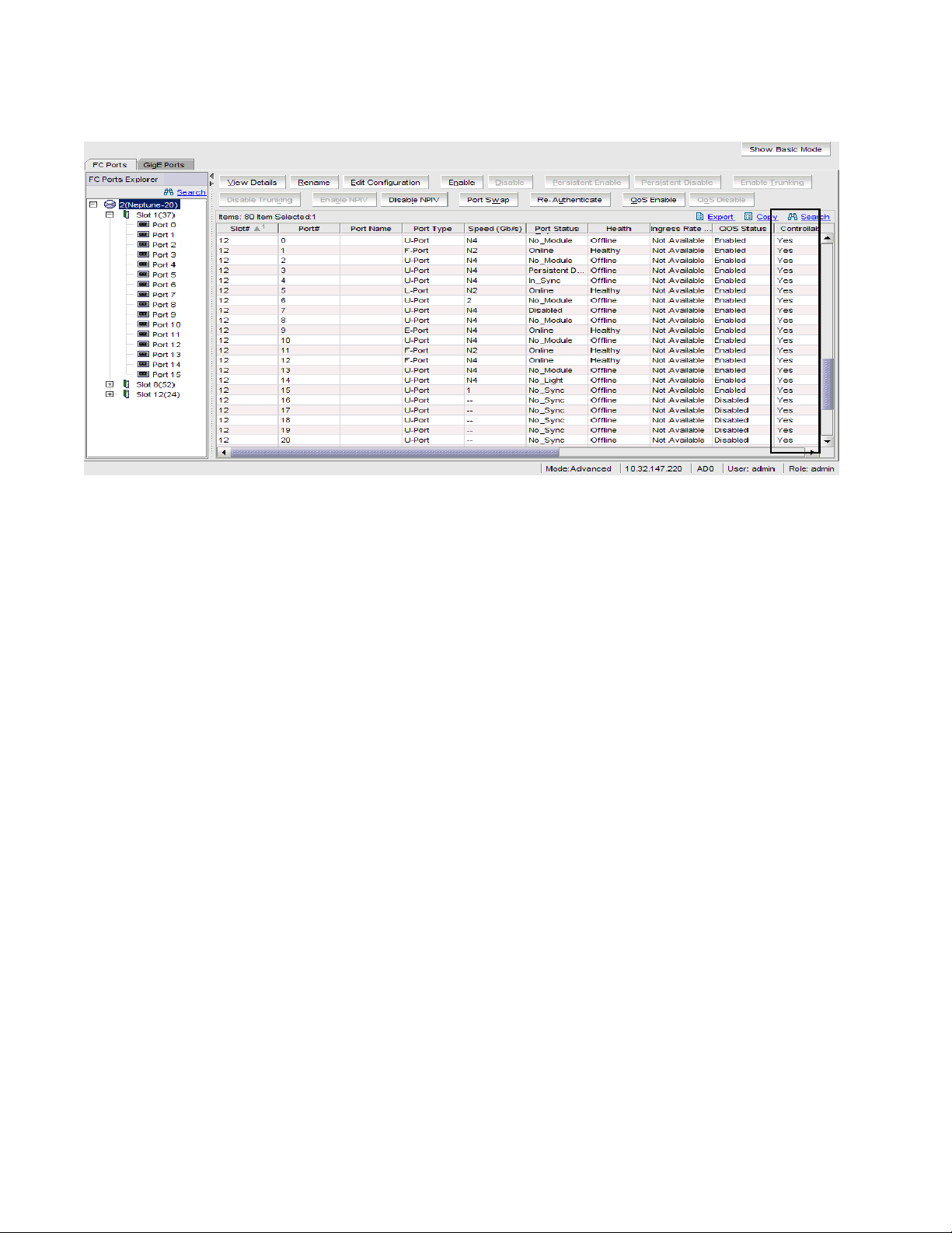
FIGURE 35 Port Administration window, Table view
Configuring ports
5
Configuring ports
Web Tools provides wizards to assist you in configuring ports. This section describes how you can
configure FC ports, logical FCIP ports, GbE ports, ICL ports, and NPIV ports.
Configuring FC ports
With the FC Port Configuration wizard, you can configure allowed port types, port speed, and long
distance mode for physical ports.
The following procedure describes how to open the FC Port Configuration wizard. The wizard is
self-explanatory, so the explicit steps are not documented here.
1. Click a port in the Switch View to open the Port Administration window (see Figure 33 on
page 62).
2. Click the FC Ports tab.
Web Tools Administrator’s Guide 65
53-1000606-01
Page 86

Configuring ports
5
FIGURE 36 FC Port Configuration Wizard, FC ports
3. From the tree on the left, select the port you want to configure.
4. Click the General subtab.
5. Click the Edit Configuration button.
The FC Port Configuration wizard opens. The fields are populated with the current
configuration values.
6. Follow the steps in the wizard.
If you configure a disabled port as an EX_Port, the wizard displays the Enable Port after
configuration check box. If you select the check box, the disabled port is automatically enabled
after configuration; otherwise, the port remains in the same state after configuration.
Allowed Port Types
For FC ports, the Port Administration window displays the following values relating to port type:
Port Type This is the actual or current port type. If the port is offline, this value is the
allowed types (or U_Port, if no type constraint has been specified). If the port
is online, this value is the type the port has actually negotiated to.
Allowed Port Type The allowed or configured port type.
The allowed port types indicate any constraints on what types the port can negotiate to when it
comes up. For normal (that is, non-EX_Port) ports, the following are the allowed port types:
L_Port The port can be used to connect a loop device.
F_Port The port can be used to connect a non-loop device.
E_Port The port can be used to connect to another switch.
U_Port For a physical FC port: the port can be any one of E_Port, F_Port, or L_Port.
For a logical FC port: the port can be either VE_Port or VEX_Port.
66 Web Tools Administrator’s Guide
53-1000606-01
Page 87

Configuring ports
When the wizard prompts you to select allowed port types, if all of these boxes are selected, there
are no constraints on port type. The port will negotiate to its preferred type when the switch comes
up, depending on what type of device or switch it is connected to.
Clearing a check box guarantees that the port will not attempt to function as a port of the
unchecked type. At least one type must remain selected. L-Port and F-Port cannot both be cleared.
An FC port cannot be configured only to an E-Port and L-Port.
5
NOTE
To configure a port as an EX_Port, the switch must be capable of supporting FCR/FCIP features. The
EX_Port option is disabled in the wizard if the switch does not meet these requirements.
Long distance mode
Port long distance configuration can be performed here and in the Switch Admin Extended Fabric
tab. For information about long distance mode settings, see Chapter 13, “Administering Extended
Fabrics”.
FC Fastwrite
FC Fastwrite reduces the number of round-trip times required to write data.
For Brocade 48000 with FC4-18i, Brocade DCX Director, and 7500 switches, you can enable FC
Fastwrite. When FC Fastwrite is enabled, all GigE port, and FCIP features are disabled.
Configuring FCIP ports
With the FC Port Configuration wizard, you can configure the port type for logical FCIP ports.
Configure the port to be a VE_Port if you want to merge with the remote fabric with which you are
communicating. Configure the port to be a VEX_Port if you want to communicate with a remote
fabric without merging with it.
Admin Domain considerations: You can configure FCIP ports only when the current Admin Domain
owns the switch.
The following procedure describes how to open the FC Port Configuration wizard. The wizard is
self-explanatory, so the explicit steps are not documented here.
1. Click a port in the Switch View to open the Port Administration window.
2. Click the FC Ports tab.
3. From the tree on the left, select the logical port you want to configure.
4. Click the General subtab.
5. Click the Edit Configuration button.
The FC Port Configuration wizard opens. The fields are populated with the current
configuration values.
6. Follow the steps in the wizard.
For VEX_Ports, you will need to specify the Fabric ID. You can choose any unique fabric ID as
long as it is consistent for all VEX_Ports that connect to the same edge fabric.
Web Tools Administrator’s Guide 67
53-1000606-01
Page 88

Assigning a name to a port
5
If you configure a disabled port as a VEX_Port, the wizard provides the Enable Port after
configuration check box. If you select this check box, the disabled port is automatically
enabled after configuration. If you leave this check box cleared, the port remains in the same
state after configuration.
Configuring GbE ports
With the GigE Port Configuration wizard, you can configure IP interfaces and IP routes.
For information about setting up iSCSI Target Gateway, see Chapter 14, “Administering the iSCSI
Tar get Gateway”.
Admin Domain considerations: You can configure GbE ports only when the current Admin Domain
owns the switch.
The following procedure describes how to open the GigE Port Configuration wizard. The wizard is
self-explanatory, so the explicit steps are not documented here.
1. Click a port in the Switch View to open the Port Administration window (see Figure 33 on
page 62).
2. Click the GigE Ports tab.
3. Select the port you want to configure in the tree on the left side of the window.
4. Click Edit Configuration in the task bar.
The GigE Port Configuration wizard opens. The wizard fields are populated with the current
configuration values.
5. Follow the steps in the wizard.
Assigning a name to a port
Port names are optional. You can assign a name to an FC or FCIP port to make port grouping
easier. You can rename FC and FCIP ports too. You cannot rename GbE ports. The Port Name
column in the Ports tab displays the port name, if one exists.
Port names can be from 1 through 32 alphanumeric characters, unless Ficon Management
Server (FMS) mode is enabled; if FMS mode is enabled, port names should be limited from 1
through 24 alphanumeric characters. The comma (,), semicolon (;), and “at” symbol (@) are not
allowed.
NOTE
Although it is not required, it is recommended that port names be unique.
1. Click a port in the Switch View to open the Port Administration window.
2. Click the FC Ports tab.
3. From the tree on the left, click the switch or slot that contains the port you want to rename.
4. From the table, select the port you want to rename.
5. Click the Rename button.
6. Type a name for the port and click Rename.
68 Web Tools Administrator’s Guide
53-1000606-01
Page 89

To delete the existing port name, leave the field blank and click Rename.
Enabling and disabling a port
Use the following procedure to enable or disable a port.
1. Click a port in the Switch View to open the Port Administration window.
2. Click the FC Ports or GigE Ports tab.
3. From the tree on the left, click the switch or slot that contains the port you want to enable or
disable.
4. From the table, select one or more ports.
Use Shift-click and Ctrl-click to select multiple ports. You can select multiple ports from the
table. You cannot select multiple ports from the tree.
5. Click the Enable or Disable button.
If the button is gray (unavailable), the port is already in the enabled or disabled state. For
example, if the Enable button is unavailable, the port is already enabled.
Enabling and disabling a port
5
If you select multiple ports in both enabled and disabled states, both buttons are active. When
you click either button, the action is applied to all selected ports.
6. Click Yes in the confirmation window.
Considerations
You should understand the following limitations and conditions when you are enabling or disabling
a port:
• On FR4-18i and FC4-16IP port blades, all ports are disabled by default. You can disable and
reenable them as needed.
• If FC Routing is disabled, all EX_Ports are automatically disabled and you cannot enable them
until FC Routing is enabled.
• If a port is not licensed you cannot enable it until you install the appropriate license, such as a
Ports on Demand or N-Port ID Virtualization license (see “Activating ports” on page 71 for more
information). The Licensed field located in the General tab in the Port Administration window
indicates whether a port is licensed.
• If you disable a principal ISL port (an ISL port that has been designated by the fabric to be a
part of the path to communicate with the principal switch), the fabric reconfigures.
• If you disable a port that was connected to a device, that device is no longer accessible from
the fabric. For more information, see the Fabric OS Administrator’s Guide.
Web Tools Administrator’s Guide 69
53-1000606-01
Page 90

Persistent enabling and disabling ports
5
Persistent enabling and disabling ports
Use the following procedure to enable or disable an FC port so that it remains enabled or disabled
across switch reboots.
NOTE
Ports cannot be persistently enabled or disabled when FMS is enabled.
1. Click a port in the Switch View to open the Port Administration window.
2. Click the FC Ports or GigE Ports tab.
3. From the tree on the left, click the switch or slot that contains the port.
4. From the table, select one or more ports.
Use Shift-click and Ctrl-click to select multiple ports. You can select multiple ports from the
table. You cannot select multiple ports from the tree.
5. Click the Persistent Enable or Persistent Disable button.
If the button is gray (unavailable), the port is already in that state. For example, if the Persistent
Enable button is unavailable, the port or ports are already persistently enabled over reboots.
If you select multiple ports in both enabled and disabled states, both buttons are active. When
you click either button, the action is applied to all selected ports.
6. Click Yes in the confirmation window.
Enabling and disabling NPIV ports
The NPIV license must be installed on a switch before NPIV functionality can be enabled on any
port.
NOTE
NPIV enable/disable is not supported on EX_Ports.
For detailed information about understanding and configuring NPIV ports, see the Fabric OS
Administrator’s Guide. With Web Tools, you can only enable or disable the NPIV functionality on a
port.
Enabling NPIV ports
1. Click a port in the Switch View to open the Port Administration window.
2. Click the FC Ports tab.
3. From the tree on the left, select the logical port you want to enable.
4. Click the Enable NPIV button.
The button is unavailable if NPIV is already enabled on the port.
70 Web Tools Administrator’s Guide
53-1000606-01
Page 91

Disabling NPIV ports
1. Click a port in the Switch View to open the Port Administration window.
2. Click the FC Ports tab.
3. From the tree on the left, select the logical port you want to disable.
4. Click the Disable NPIV button.
The button is unavailable if NPIV is already disabled on the port.
Enabling and disabling QoS ports
For detailed information about understanding and configuring QoS ports, see the Fabric OS
Administrator’s Guide. With Web Tools, you can only enable or disable the QoS functionality on a
port.
Enabling QoS
1. Click a port in the Switch View to open the Port Administration window.
Enabling and disabling QoS ports
5
2. Click the Show Advanced Mode button.
3. From the tree on the left, select the logical port you want to disable.
4. Click the Enable QoS button.
5. Click Yes on the confirmation window.
Disabling QoS
1. Click a port in the Switch View to open the Port Administration window.
2. Click the Show Advanced Mode button.
3. From the tree on the left, select the logical port you want to disable.
4. Click the Disable QoS button.
5. Click Yes on the confirmation window.
Activating ports
Brocade switches come with a preset number of ports enabled. Additional ports can be enabled
using the Ports on Demand (POD) licenses and the Dynamic Ports on Demand (DPOD) feature (for
supported switches only).
The button is unavailable if QoS is already enabled on the port.
The button is unavailable if QoS is already disabled on the port.
Web Tools Administrator’s Guide 71
53-1000606-01
Page 92

Activating ports
5
Ports on Demand is ready to be unlocked in the switch firmware. The license might be part of the
licensed Paper Pack supplied with switch software, or you can purchase the license separately
from your switch vendor, who will provide you with a key to unlock it. You can install up to two Ports
on Demand licenses on each switch.
Tab le 5 shows the ports that are enabled by default and the ports that can be enabled after you
install the first and second Ports on Demand licenses for each switch type, and the ports that can
be enabled with the Dynamic PODs feature.
TABLE 5 Ports Enabled with POD Licenses and DPOD Feature
Switch Name Enabled by
Default
Enabled with Ports on Demand
License(s)
Enabled with the Dynamic Ports on
Demand Feature
Brocade 200E 0–7 8–11
12–15
Brocade 5000
Brocade 4100
Brocade 4016 0-7, 10-13 8, 9, 14, 15 Any available ports
Brocade 4018 2-11 12-17 Any available ports
Brocade 4020 0-7, 15, 16 8, 9, 17-19
Brocade 4024 1-8, 17-20 9-12, 21, 22
Brocade 4900 0–31 32–47
0–15 16–23
24–31
10-14
0, 13-16, 23
48–63
Not supported
Not supported
Any available ports
Any available ports
Not supported
For the Brocade 4016, 4018, 4020, and 4024 switches only, you can use the Dynamic Ports on
Demand (DPOD) feature, which allows you to choose which ports to enable (instead of predefined
sets of ports) after the POD license(s) is installed. Web Tools allows you only to enable or disable
the DPOD functionality on a port. To configure DPOD, see the Fabric OS Administrator’s Guide.
In the Port Administration window, the Licensed attribute indicates whether a port is licensed (yes),
whether it can be license (possible) because there are free licenses available (only applicable with
the Dynamic POD feature), or whether it is not licensed and cannot be licensed because there is no
available license.
After the license keys are installed, you must enable the ports. You can do so without disrupting
switch operation, as described in “Enabling and disabling a port” on page 69. Alternatively, you can
disable and reenable the switch to activate all ports as described in “Enabling and disabling a
switch” on page 34.
To unlock a Ports on Demand license, you can use the supplied license key or generate a license
key. If you need to generate a key, open an Internet browser and go to the Brocade Web site at
www.brocade.com. Click Products > Software License Keys and follow the instructions to generate
the key.
Enabling Ports on Demand
1. Install the Brocade Ports on Demand licensed product. For instructions, see “Activating a
license on a switch” on page 41.
2. Enable the ports as described in “Enabling and disabling a port” on page 69.
72 Web Tools Administrator’s Guide
53-1000606-01
Page 93

Activating ports
If you remove a Ports on Demand license, the licensed ports are disabled after the next platform
reboot or the next port deactivation.
5
Enabling Dynamic Ports on Demand
You must be logged in as Admin to enable or disable the Dynamic PODs feature.
NOTE
The Dynamic PODs feature is supported on the Brocade 4018, 4020, and 4024 switches only. If you
click the Enable DPOD button on an unsupported switch, an error message displays.
1. Click a port in the Switch View to open the Port Administration window.
2. Click the FC Ports or GigE Ports tab.
3. From the tree on the left, click the switch or the slot that contains the port.
4. Click the Enable DPOD button to enable the licensing mechanism to be dynamic. If the button
says Disable DPOD, the licensing mechanism is already set to dynamic.
The existing POD associations and assignments are set as the initial Dynamic POD
associations.
Two fields are displayed:
• Available Licenses indicate the number of free licenses. These can be allocated for
any port.
• Total Li cen ses indicate the total number of licenses.
Disabling Dynamic Ports on Demand
NOTE
Disabling DPODs causes traffic disruption. Any prior port associations and assignments are lost the
next time the switch is rebooted.
You must be logged in as Admin to enable or disable the Dynamic PODs feature.
1. Click a port in the Switch View to open the Port Administration window.
2. Click the FC Ports or GigE Ports tab.
3. From the tree on the left, click the switch or the slot that contains the port.
4. Click the Disable DPOD button to set the licensing mechanism to static. If the button displays
Enable DPOD, the licensing mechanism is already set to static.
Reserving and releasing licenses on a port basis
You must be logged in as Admin to reserve and release licenses.
NOTE
If the Admin Domains feature is enabled, the Dynamic POD configuration is only applied to the ports
if the switch is a member of the current Admin Domain.
The Dynamic PODs feature is supported on the Brocade 4018, 4020, and 4024 switches only.
Web Tools Administrator’s Guide 73
53-1000606-01
Page 94

Swapping port index
5
You must disable the port or switch before reserving or releasing a license.
1. Click a port in the Switch View to open the Port Administration window.
2. Click the FC Ports or GigE Ports tab.
3. From the tree on the left, click the switch or the slot that contains the port.
The License column identifies the port license status:
• If the port has a license allocated, the License field contains the value Yes.
• If the port does not have a license allocated and there are no free licenses that can be
• If the port does not have a license allocated and there are licenses that can be
You can reserve or release a license on any port that has a license allocated.
To reserve a license, click Reserve License in the Port Administration window.
To release a license, click Release License in the Port Administration window.
Swapping port index
allocated, the License field contains the value No.
allocated to the port, the License field contains the value Possible.
If a port malfunctions, or if you want to connect to different devices without having to re-wire your
infrastructure, you can move traffic from one port to another (swap ports) without changing the I/O
Configuration Data Set (IOCDS) on the mainframe computer.
When you perform a port swap, Web Tools automatically disables the two ports, swaps the area
IDs, and enables the ports.
Swapping ports
1. Click a port in the Switch View to open the Port Administration window.
2. Click the FC Ports tab.
3. Click the Advanced button.
4. From the tree on the left, select the port you want to swap.
5. Click the Port Swap button.
6. Type the number of the port with which you want to swap the current port. If the port is on a
blade, you must also provide the slot number.
7. C li c k Swap.
Determining if a port index has been swapped with another switch port
1. Click a port in the Switch View to open the Port Administration window.
2. Click the FC Ports tab.
3. Click the Advanced button.
4. From the tree on the left, select the port you want to swap.
5. Click the General tab.
74 Web Tools Administrator’s Guide
53-1000606-01
Page 95

Swapping port index
The Port Index attribute on the General tab indicates whether a port has been swapped. For
ports that have been swapped, the attribute name displays as Port Index (Swapped), as shown
in Figure 37. The value indicates with which port index the port has been swapped.
5
FIGURE 37 Swapping a Port Index
Web Tools Administrator’s Guide 75
53-1000606-01
Page 96

Swapping port index
5
76 Web Tools Administrator’s Guide
53-1000606-01
Page 97

Chapter
Administering ISL Trunking
In this chapter
This chapter contains the following information:
•About Interswitch Link Trunking . . . . . . . . . . . . . . . . . . . . . . . . . . . . . . . . . . . 77
•Viewing trunk group information . . . . . . . . . . . . . . . . . . . . . . . . . . . . . . . . . . 78
•Disabling or reenabling trunking mode on a port . . . . . . . . . . . . . . . . . . . . . 78
About Interswitch Link Trunking
Interswitch link (ISL) trunking optimizes network performance by forming trunking groups that can
distribute traffic across a shared bandwidth.
A trunking license is required on each switch that participates in the trunk. For details on obtaining
and installing licensed features, see “Managing licensed features” on page 40. For additional
information about ISL Trunking, see the Fabric OS Administrator’s Guide.
6
Use the Tru nking tab of the Switch Administration window to view trunks through Web Tools (see
Figure 38).
Web Tools Administrator’s Guide 77
53-1000606-01
Page 98

Viewing trunk group information
6
FIGURE 38 Trunking tab
Viewing trunk group information
Use this procedure to display the following information about ISL Trunking grou ps:
• Trunk gro up number identifier
• Master port
• Member ports
1. Open the Switch Administration window as described on page 29.
2. Click the Tru nking tab.
3. Optional: Click Refresh to refresh the information.
Disabling or reenabling trunking mode on a port
When the trunking license is activated, trunks are automatically established on eligible ISLs and
trunking capability is enabled by default on all ports. Use the following procedure to disable
trunking on a port or to reenable trunking if it has been disabled.
Trunking is not supported on logical ports, GbE ports, or EX_Ports.
78 Web Tools Administrator’s Guide
53-1000606-01
Page 99

Disabling or reenabling trunking mode on a port
1. Click a port in the Switch View to open the Port Administration window (see Figure 33 on
page 62).
2. Click the FC Ports tab.
Trunking mode does not apply to GbE ports.
3. From the tree on the left, click the switch name or slot name.
4. From the table, select the port that you want to trunk.
You can select multiple ports from the table. You cannot select multiple ports from the tree.
Trunking mode does not apply to logical ports.
5. Choose the Advanced Mode of Ports Admin.
If the button is unavailable, the port is already in that state.
6. Click Yes in the confirmation window.
6
Admin Domain considerations
You can enable and disable trunking for a port only when the current Admin Domain owns the
switch. You can log into a switch that is not in your Admin Domain, but most of the functionality will
be unavailable.
Web Tools Administrator’s Guide 79
53-1000606-01
Page 100

Disabling or reenabling trunking mode on a port
6
80 Web Tools Administrator’s Guide
53-1000606-01
 Loading...