

Page 1

53-1003169-01
27 June 2014
Web Tools
Administrator's Guide
Supporting Fabric OS v7.3.0
Page 2

©
2014, Brocade Communications Systems, Inc. All Rights Reserved.
Brocade, the B-wing symbol, Brocade Assurance, ADX, AnyIO, DCX, Fabric OS, FastIron, HyperEdge, ICX, MLX, MyBrocade, NetIron,
OpenScript, VCS, VDX, and Vyatta are registered trademarks, and The Effortless Network and the On-Demand Data Center are trademarks
of Brocade Communications Systems, Inc., in the United States and in other countries. Other brands and product names mentioned may be
trademarks of others.
Notice: This document is for informational purposes only and does not set forth any warranty, expressed or implied, concerning any
equipment, equipment feature, or service offered or to be offered by Brocade. Brocade reserves the right to make changes to this document
at any time, without notice, and assumes no responsibility for its use. This informational document describes features that may not be
currently available. Contact a Brocade sales office for information on feature and product availability. Export of technical data contained in
this document may require an export license from the United States government.
The authors and Brocade Communications Systems, Inc. assume no liability or responsibility to any person or entity with respect to the
accuracy of this document or any loss, cost, liability, or damages arising from the information contained herein or the computer programs that
accompany it.
The product described by this document may contain open source software covered by the GNU General Public License or other open
source license agreements. To find out which open source software is included in Brocade products, view the licensing terms applicable to
the open source software, and obtain a copy of the programming source code, please visit http://www.brocade.com/support/oscd.
Page 3

Contents
Preface...................................................................................................................................13
Document conventions....................................................................................13
Text formatting conventions................................................................ 13
Command syntax conventions............................................................ 13
Notes, cautions, and warnings............................................................ 14
Brocade resources.......................................................................................... 15
Contacting Brocade Technical Support...........................................................15
Document feedback........................................................................................ 16
About This Document ............................................................................................................. 17
Supported hardware and software.................................................................. 17
What’s new in this document.......................................................................... 18
Introducing Web Tools.............................................................................................................19
Web Tools overview........................................................................................19
Web Tools, the EGM license, and Brocade Network Advisor......................... 19
Web Tools features enabled by the EGM license............................... 20
Web Tools functionality moved to Brocade Network Advisor..............21
System requirements...................................................................................... 23
Setting refresh frequency for Internet Explorer................................... 24
Deleting temporary Internet files used by Java applications............... 25
Java installation on the workstation................................................................ 26
Installing the JRE on your Solaris or Linux client workstation.............26
Installing patches on Solaris............................................................... 26
Installing the Java Plug-in on Windows...............................................27
Java Plug-in configuration...............................................................................27
Enabling Java content in the browser................................................. 27
Configuring the Java Plug-in for Windows.......................................... 27
Configuring the Java Plug-in for Mozilla family browsers....................28
Value line licenses.......................................................................................... 28
Opening Web Tools........................................................................................ 29
Logging in............................................................................................29
Logging out......................................................................................... 32
Role-Based Access Control............................................................................ 32
Session management..................................................................................... 33
Ending a Web Tools session...............................................................33
Web Tools system logs .................................................................................. 33
SupportSave logs............................................................................................34
Requirements for IPv6 support....................................................................... 35
Web Tools Administrator's Guide
53-1003169-01
Using the Web Tools Interface................................................................................................. 37
Viewing Switch Explorer..................................................................................37
Persisting GUI preferences................................................................. 39
Tabs.................................................................................................... 40
Fabric Tree..........................................................................................40
Changing the Admin Domain context..................................................41
Switch View buttons............................................................................ 41
3
Page 4

Switch View.......................................................................................41
Switch Events and Switch Information..............................................43
Free Professional Management tool................................................. 45
Displaying tool tips........................................................................................ 45
Right-click options.........................................................................................45
Refresh rates.................................................................................................46
Displaying switches in the fabric................................................................... 47
Recommendations for working with Web Tools............................................47
Opening a Telnet or SSH client window....................................................... 48
Collecting logs for troubleshooting................................................................48
Managing Fabrics and Switches............................................................................................ 51
Fabric and switch management overview.....................................................51
Opening the Switch Administration window...................................... 52
Configuring IP and subnet mask information................................................ 53
Configuring Netstat Auto Refresh................................................................. 54
Configuring a syslog IP address................................................................... 54
Removing a syslog IP address......................................................................55
Configuring IP filtering...................................................................................55
Blade management.......................................................................................56
Enabling or disabling a blade............................................................56
Setting a slot-level IP address...........................................................57
Viewing IP addresses........................................................................58
Switch configuration......................................................................................58
Enabling and disabling a switch........................................................58
Enabling and disabling switch persistent.......................................... 58
Changing the switch name................................................................59
Changing the switch domain ID........................................................ 59
Viewing and printing a switch report................................................. 60
Setting a principal switch...................................................................60
Switch restart................................................................................................ 61
Performing a fast boot.......................................................................61
Performing a reboot.......................................................................... 61
System configuration parameters................................................................. 62
WWN-based persistent PID assignment...........................................62
Configuring fabric settings.................................................................63
Enabling insistent domain ID mode...................................................64
Configuring virtual channel settings.................................................. 64
Configuring arbitrated loop parameters............................................ 65
Configuring system services............................................................. 66
Configuring CSCTL QoS mode.........................................................66
Configuring signed firmware............................................................. 66
Licensed feature management..................................................................... 67
Activating a license on a switch........................................................ 67
Assigning slots for a license key....................................................... 67
Removing a license from a switch.....................................................68
Universal time-based licensing......................................................... 68
High Availability overview..............................................................................69
Admin Domain considerations.......................................................... 69
Launching the High Availability window............................................ 69
Synchronizing services on the CP.................................................... 70
Initiating a CP failover....................................................................... 71
Event monitoring........................................................................................... 71
Displaying switch events...................................................................72
Filtering switch events.......................................................................72
Filtering events by event severity levels............................................73
Filtering events by message ID.........................................................73
4
Web Tools Administrator's Guide
53-1003169-01
Page 5

Filtering events by service component................................................73
Displaying the Name Server entries................................................................74
Printing the Name Server entries........................................................ 74
Displaying Name Server information for a particular device............... 74
Displaying zone members for a particular device............................... 75
Physically locating a switch using beaconing..................................................75
Locating logical switches using chassis beaconing........................................ 75
Virtual Fabrics overview.................................................................................. 76
Selecting a logical switch from the Switch View..................................76
Viewing logical ports........................................................................... 77
Maintaining Configurations and Firmware............................................................................... 79
Creating a configuration backup file................................................................79
Restoring a configuration................................................................................ 80
Admin Domain configuration maintenance..................................................... 81
Uploading and downloading from USB storage.............................................. 82
Performing a firmware download.................................................................... 82
Managing Administrative Domains..........................................................................................85
Administrative Domain overview..................................................................... 85
Requirements for Admin Domains...................................................... 85
User-defined Admin Domains............................................................. 85
System-defined Admin Domains.........................................................86
Admin Domain membership................................................................87
Enabling Admin Domains................................................................................87
Admin Domain window....................................................................................87
Opening the Admin Domain window................................................... 89
Refreshing fabric information.............................................................. 89
Refreshing Admin Domain information............................................... 89
Saving local Admin Domain changes..................................................90
Closing the Admin Domain window.....................................................90
Creating and populating domains................................................................... 90
Creating an Admin Domain................................................................. 91
Adding ports or switches to the fabric................................................. 91
Activating or deactivating an Admin Domain.......................................92
Modifying Admin Domain members................................................................ 92
Renaming Admin Domains................................................................. 93
Deleting Admin Domains.....................................................................93
Clearing the Admin Domain configuration...........................................93
Web Tools Administrator's Guide
53-1003169-01
Managing Ports.......................................................................................................................95
Port management overview............................................................................ 95
Opening the Port Admin tab................................................................95
Port Admin tab components................................................................96
Controllable ports................................................................................ 99
Configuring FC ports....................................................................................... 99
Allowed port types.............................................................................100
Speed................................................................................................101
Long distance mode..........................................................................101
Ingress rate limit................................................................................101
Available buffer credit calculation......................................................103
Assigning a name to a port........................................................................... 103
Port beaconing.............................................................................................. 103
Enabling and disabling a port........................................................................104
Considerations for enabling or disabling a port.................................104
5
Page 6

Persistent enabling and disabling ports...................................................... 105
Configuring NPIV ports............................................................................... 106
Port activation............................................................................................. 106
Enabling Ports on Demand............................................................. 108
Enabling Dynamic Ports on Demand.............................................. 108
Disabling Dynamic Ports on Demand............................................. 108
Diagnostic ports.............................................................................. 109
Reserving and releasing licenses on a port basis...........................109
Port swapping index....................................................................................110
Port swapping................................................................................. 110
Determining if a port index was swapped with another switch
port............................................................................................ 111
Configuring port binding..............................................................................112
Unbinding a port..............................................................................113
Configuring BB credits on an F_Port.......................................................... 113
Configuring ALPA .......................................................................................114
Configuring port octet speed combination ................................................. 115
Configuring CSCTL.....................................................................................116
Enabling CSCTL mode................................................................... 117
Disabling CSCTL mode...................................................................117
Configuring compression and encryption....................................................117
Enabling or disabling encryption..................................................... 118
Enabling or disabling compression................................................. 118
Displaying compression ratio.......................................................... 118
Forward Error Correction............................................................................ 119
In-Band Management..................................................................................119
GigE port modes......................................................................................... 120
Enabling ISL Trunking......................................................................................................... 121
ISL Trunking overview.................................................................................121
Disabling or enabling ISL Trunking ............................................................ 121
Admin Domain considerations........................................................ 122
Viewing trunk group information................................................................. 122
F_Port trunk groups.................................................................................... 123
Creating and maintaining F_Port trunk groups............................... 123
Monitoring Performance..................................................................................................... 125
Performance Monitor overview................................................................... 125
Basic monitoring .............................................................................125
Advanced monitoring...................................................................... 125
Performance graphs........................................................................126
Admin Domain considerations........................................................ 126
Predefined performance graphs..................................................... 126
User-defined graphs........................................................................129
Canvas configurations.....................................................................129
Opening the Performance Monitor window.................................................130
Creating basic performance monitor graphs...............................................130
Customizing basic monitoring graphs......................................................... 131
Advanced performance monitoring graphs................................................. 133
Creating SID/DID Performance graphs...........................................133
Creating the SCSI vs. IP Traffic graph............................................134
Creating SCSI command graphs.................................................... 134
Tunnel and TCP performance monitoring graphs.......................................135
Tunnel and TCP graph chart properties..........................................136
Saving graphs to a canvas..........................................................................136
Adding graphs to an existing canvas.......................................................... 137
6
Web Tools Administrator's Guide
53-1003169-01
Page 7

Printing graphs.............................................................................................. 137
Modifying graphs...........................................................................................137
Administering Zoning............................................................................................................139
Zoning overview............................................................................................ 139
Basic zones.......................................................................................139
Traffic Isolation zones....................................................................... 139
LSAN zone requirements.................................................................. 139
QoS zone requirements.................................................................... 140
Zoning configurations ...................................................................................140
Opening the Zone Admin window..................................................... 140
Setting the default zoning mode........................................................140
Zoning management..................................................................................... 141
Refreshing fabric information............................................................ 144
Refreshing Zone Administration window information........................ 144
Saving local zoning changes.............................................................145
Selecting a zoning view.....................................................................145
Creating and populating zone aliases............................................... 146
Adding and removing members of a zone alias................................ 146
Renaming zone aliases.....................................................................147
Deleting zone aliases........................................................................ 147
Creating and populating zones......................................................... 148
Adding and removing members of a zone........................................ 148
Renaming zones............................................................................... 149
Cloning zones................................................................................... 149
Deleting zones.................................................................................. 149
Creating and populating enhanced Traffic Isolation zones............... 150
Zone configuration and zoning database management................................ 151
Creating zone configurations............................................................ 151
Adding or removing zone configuration members.............................152
Renaming zone configurations..........................................................152
Cloning zone configurations..............................................................153
Deleting zone configurations.............................................................153
Enabling zone configurations............................................................ 153
Disabling zone configurations........................................................... 154
Displaying enabled zone configurations............................................154
Viewing the enabled zone configuration name without opening
the Zone Administration window..................................................155
Viewing detailed information about the enabled zone configuration. 155
Adding a WWN to multiple aliases and zones.................................. 155
Removing a WWN from multiple aliases and zones......................... 156
Replacing a WWN in multiple aliases and zones..............................156
Searching for zone members............................................................ 157
Clearing the zoning database........................................................... 157
Zone configuration analysis.............................................................. 157
Best practices for zoning...............................................................................158
Web Tools Administrator's Guide
53-1003169-01
Working with Diagnostic Features..........................................................................................159
Trace dumps................................................................................................. 159
How a trace dump is used.................................................................159
Setting up automatic trace dump transfers....................................... 160
Specifying a remote server............................................................... 160
Enabling automatic transfer of trace dumps......................................160
Disabling automatic trace uploads.................................................... 160
Displaying switch information........................................................................161
Viewing detailed fan hardware status............................................... 162
7
Page 8

Viewing the temperature status.......................................................162
Viewing the power supply status.....................................................163
Checking the physical health of a switch........................................ 163
Defining switch policy..................................................................................165
Port LED interpretation................................................................................166
Port icon colors............................................................................... 166
Using the FC-FC Routing Service......................................................................................... 167
Fibre Channel Routing overview.................................................................167
Supported switches for Fibre Channel Routing.......................................... 168
Setting up FC-FC routing............................................................................ 168
FC-FC routing management....................................................................... 169
Opening the FC Routing module.................................................... 169
Viewing and managing LSAN fabrics..............................................170
Viewing EX_Ports....................................................................................... 170
Configuring an EX_Port.............................................................................. 171
Editing the configuration of an EX_Port.......................................... 171
Configuring FCR router port cost................................................................ 172
Viewing LSAN zones...................................................................................172
Viewing LSAN devices....................................................................172
Configuring the backbone fabric ID.............................................................173
Using the Access Gateway...................................................................................................175
Access Gateway overview.......................................................................... 175
Viewing Switch Explorer for Access Gateway mode.................................. 175
Access Gateway mode .............................................................................. 176
Restricted access in the Port Admin tab......................................... 176
Enabling Access Gateway mode................................................................ 177
Disabling Access Gateway mode................................................................177
Viewing the Access Gateway settings........................................................ 178
Port configuration........................................................................................178
Editing a Port...................................................................................178
Creating port groups....................................................................... 179
Editing or viewing port groups.........................................................180
Deleting port groups........................................................................181
Defining custom primary F-N port mapping.................................... 181
Defining custom static F-N port mapping........................................181
Defining custom WWN-N port mappings........................................ 182
Access Gateway policy modification...........................................................182
Path Failover and Failback policies.................................................182
Modifying Path Failover and Failback policies................................ 182
Enabling the Automatic Port Configuration policy.......................................183
Administering Fabric Watch................................................................................................ 185
Fabric Watch overview................................................................................185
Administering Extended Fabrics.......................................................................................... 187
Extended link buffer allocation overview.....................................................187
Configuring a port for long distance............................................................ 189
Routing Traffic.................................................................................................................... 191
Routing overview.........................................................................................191
8
Web Tools Administrator's Guide
53-1003169-01
Page 9

Viewing fabric shortest path first routing....................................................... 192
Configuring dynamic load sharing.................................................................193
Lossless dynamic load sharing......................................................... 193
Specifying frame order delivery.....................................................................194
Configuring the link cost for a port................................................................ 194
Configuring Standard Security Features.................................................................................197
User-defined accounts.................................................................................. 197
Virtual Fabrics considerations........................................................... 198
Admin Domain considerations.......................................................... 198
Viewing user account information..................................................... 199
Creating user-defined accounts........................................................ 199
Deleting user-defined accounts.........................................................202
Changing user account parameters ................................................. 202
Maintaining passwords......................................................................204
User-defined roles.........................................................................................206
Guidelines and restrictions................................................................206
Creating a user-defined role..............................................................207
Editing a user-defined role................................................................ 208
Access control list policy configuration..........................................................209
Virtual Fabrics considerations........................................................... 209
Admin Domain considerations.......................................................... 209
Creating an SCC, DCC, or FCS policy..............................................209
Editing an SCC, DCC, or FCS policy................................................ 210
Deleting all SCC, DCC, or FCS policies............................................210
Activating all SCC, DCC, or FCS policies......................................... 210
Distributing an SCC, DCC, or FCS policy......................................... 211
Moving an FCS policy switch position...............................................211
Configuring Advanced Device Security policy ..................................211
Fabric-Wide Consistency Policy configuration.............................................. 212
Authentication policy configuration................................................................213
Configuring authentication policies for E_Ports................................ 213
Configuring authentication policies for F_Ports.................................213
Distributing authentication policies....................................................214
Re-authenticating policies................................................................. 214
Setting a shared secret key pair........................................................214
Modifying a shared secret key pair................................................... 215
Setting the Switch Policy Authentication mode................................. 215
SNMP configuration...................................................................................... 215
Setting SNMP trap levels.................................................................. 215
Changing the systemGroup configuration parameters......................216
Setting SNMPv1 configuration parameters....................................... 216
Setting SNMPv3 configuration parameters....................................... 216
Changing the access control configuration....................................... 217
RADIUS management...................................................................................217
Enabling and disabling RADIUS....................................................... 218
Configuring RADIUS......................................................................... 218
Modifying the RADIUS server........................................................... 219
Modifying the RADIUS server order..................................................219
Removing a RADIUS server............................................................. 220
Active Directory service management...........................................................220
Enabling Active Directory service......................................................220
Modifying Active Directory service.................................................... 221
Removing Active Directory service................................................... 221
TACACS+ management................................................................................221
Enabling and disabling TACACS+.................................................... 221
Configuring TACACS+...................................................................... 222
Web Tools Administrator's Guide
53-1003169-01
9
Page 10

Modifying TACACS+....................................................................... 222
Removing TACACS+...................................................................... 222
IPsec concepts............................................................................................223
Transport mode and tunnel mode...................................................224
IPsec header options...................................................................... 224
Basic IPsec configurations..............................................................225
Internet Key Exchange concepts.................................................... 226
IPsec over management ports.................................................................... 228
Enabling the Ethernet IPsec policies ............................................. 228
Establishing an IKE policy...............................................................229
Creating a security association....................................................... 229
Creating an SA proposal.................................................................230
Adding an IPsec transform policy....................................................230
Adding an IPsec selector................................................................ 231
Manually creating an SA................................................................. 231
Editing an IKE or IPsec policy.........................................................232
Deleting an IKE or IPsec policy.......................................................232
Establishing authentication policies for HBAs.............................................233
Administering FICON CUP Fabrics....................................................................................... 235
FICON CUP fabrics overview......................................................................235
Enabling port-based routing........................................................................236
Enabling or disabling FICON Management Server mode...........................237
FMS parameter configuration......................................................................237
Configuring FMS mode parameters................................................238
Displaying code page information...............................................................239
Viewing the control device state................................................................. 239
Allow / Prohibit Matrix configuration............................................................240
Viewing Allow / Prohibit Matrix configurations.................................241
Modifying Allow / Prohibit Matrix configurations..............................241
Activating an Allow / Prohibit Matrix configuration.......................... 242
Copying an Allow / Prohibit Matrix configuration.............................243
Deleting an Allow / Prohibit Matrix configuration.............................243
CUP logical path configuration....................................................................243
Viewing CUP logical path configurations........................................ 243
Configuring CUP logical paths........................................................ 244
Link Incident Registered Recipient configuration........................................244
Viewing Link Incident Registered Recipient configurations............ 244
Configuring LIRRs...........................................................................244
Displaying Request Node Identification Data .............................................245
10
Configuring FCoE with Web Tools.........................................................................................247
Web Tools and FCoE overview...................................................................247
Web Tools, the EGM license, and Brocade Network Advisor.....................247
Port information that is unique to FCoE.......................................... 248
Switch administration and FCoE.................................................................248
FCoE configuration tasks............................................................................249
Quality of Service configuration.................................................................. 249
Editing the DCB map.......................................................................249
Adding a traffic class map...............................................................250
LLDP-DCBX configuration.......................................................................... 250
Configuring global LLDP characteristics......................................... 251
Adding an LLDP profile................................................................... 252
Configuring DCB interfaces.........................................................................253
Configuring a link aggregation group ......................................................... 254
Configuring VLANs......................................................................................254
Web Tools Administrator's Guide
53-1003169-01
Page 11

Configuring FCoE login groups..................................................................... 255
Displaying FCoE port information................................................................. 256
Displaying LAG information...........................................................................257
Displaying VLAN information........................................................................ 257
Displaying FCoE login groups.......................................................................257
Displaying QoS information...........................................................................257
Displaying LLDP-DCBX information..............................................................257
Displaying DCB interface statistics............................................................... 258
Configuring a DCB interface from the Switch View.......................................258
Configuring a DCB interface from the Port Admin panel...............................258
Enabling and disabling a LAG.......................................................................259
Enabling and disabling LLDP........................................................................ 259
Enabling and disabling QoS priority-based flow control................................259
Enabling and disabling FCoE ports...............................................................260
Limitations........................................................................................................................... 261
General Web Tools limitations...................................................................... 261
Index.................................................................................................................................... 267
Web Tools Administrator's Guide 11
53-1003169-01
Page 12

12 Web Tools Administrator's Guide
53-1003169-01
Page 13

Preface
● Document conventions....................................................................................................13
● Brocade resources.......................................................................................................... 15
● Contacting Brocade Technical Support...........................................................................15
● Document feedback........................................................................................................ 16
Document conventions
The document conventions describe text formatting conventions, command syntax conventions, and
important notice formats used in Brocade technical documentation.
Text formatting conventions
Text formatting conventions such as boldface, italic, or Courier font may be used in the flow of the text
to highlight specific words or phrases.
Format
bold text
italic text
Courier font
Description
Identifies command names
Identifies keywords and operands
Identifies the names of user-manipulated GUI elements
Identifies text to enter at the GUI
Identifies emphasis
Identifies variables and modifiers
Identifies paths and Internet addresses
Identifies document titles
Identifies CLI output
Identifies command syntax examples
Command syntax conventions
Bold and italic text identify command syntax components. Delimiters and operators define groupings of
parameters and their logical relationships.
Convention
bold text Identifies command names, keywords, and command options.
italic text Identifies a variable.
Description
Web Tools Administrator's Guide 13
53-1003169-01
Page 14

Notes, cautions, and warnings
Convention Description
value In Fibre Channel products, a fixed value provided as input to a command
[ ] Syntax components displayed within square brackets are optional.
option is printed in plain text, for example, --show WWN.
Default responses to system prompts are enclosed in square brackets.
{ x | y | z } A choice of required parameters is enclosed in curly brackets separated by
x | y A vertical bar separates mutually exclusive elements.
< > Nonprinting characters, for example, passwords, are enclosed in angle
...
\
vertical bars. You must select one of the options.
In Fibre Channel products, square brackets may be used instead for this
purpose.
brackets.
Repeat the previous element, for example, member[member...].
Indicates a “soft” line break in command examples. If a backslash separates
two lines of a command input, enter the entire command at the prompt without
the backslash.
Notes, cautions, and warnings
Notes, cautions, and warning statements may be used in this document. They are listed in the order of
increasing severity of potential hazards.
NOTE
A Note provides a tip, guidance, or advice, emphasizes important information, or provides a reference
to related information.
ATTENTION
An Attention statement indicates a stronger note, for example, to alert you when traffic might be
interrupted or the device might reboot.
CAUTION
A Caution statement alerts you to situations that can be potentially hazardous to you or cause
damage to hardware, firmware, software, or data.
DANGER
A Danger statement indicates conditions or situations that can be potentially lethal or
extremely hazardous to you. Safety labels are also attached directly to products to warn of
these conditions or situations.
14 Web Tools Administrator's Guide
53-1003169-01
Page 15

Brocade resources
Visit the Brocade website to locate related documentation for your product and additional Brocade
resources.
You can download additional publications supporting your product at www.brocade.com. Select the
Brocade Products tab to locate your product, then click the Brocade product name or image to open the
individual product page. The user manuals are available in the resources module at the bottom of the
page under the Documentation category.
To get up-to-the-minute information on Brocade products and resources, go to MyBrocade. You can
register at no cost to obtain a user ID and password.
Release notes are available on MyBrocade under Product Downloads.
White papers, online demonstrations, and data sheets are available through the Brocade website.
Contacting Brocade Technical Support
Brocade resources
As a Brocade customer, you can contact Brocade Technical Support 24x7 online, by telephone, or by email. Brocade OEM customers contact their OEM/Solutions provider.
Brocade customers
For product support information and the latest information on contacting the Technical Assistance
Center, go to http://www.brocade.com/services-support/index.html.
If you have purchased Brocade product support directly from Brocade, use one of the following methods
to contact the Brocade Technical Assistance Center 24x7.
Online Telephone E-mail
Preferred method of contact for nonurgent issues:
• My Cases through MyBrocade
• Software downloads and licensing
tools
• Knowledge Base
Required for Sev 1-Critical and Sev
2-High issues:
• Continental US: 1-800-752-8061
• Europe, Middle East, Africa, and
Asia Pacific: +800-AT FIBREE
(+800 28 34 27 33)
• For areas unable to access toll
free number: +1-408-333-6061
• Toll-free numbers are available in
many countries.
support@brocade.com
Please include:
• Problem summary
• Serial number
• Installation details
• Environment description
Brocade OEM customers
If you have purchased Brocade product support from a Brocade OEM/Solution Provider, contact your
OEM/Solution Provider for all of your product support needs.
• OEM/Solution Providers are trained and certified by Brocade to support Brocade® products.
• Brocade provides backline support for issues that cannot be resolved by the OEM/Solution Provider.
Web Tools Administrator's Guide 15
53-1003169-01
Page 16

Document feedback
• Brocade Supplemental Support augments your existing OEM support contract, providing direct
access to Brocade expertise. For more information, contact Brocade or your OEM.
• For questions regarding service levels and response times, contact your OEM/Solution Provider.
Document feedback
To send feedback and report errors in the documentation you can use the feedback form posted with
the document or you can e-mail the documentation team.
Quality is our first concern at Brocade and we have made every effort to ensure the accuracy and
completeness of this document. However, if you find an error or an omission, or you think that a topic
needs further development, we want to hear from you. You can provide feedback in two ways:
• Through the online feedback form in the HTML documents posted on www.brocade.com.
• By sending your feedback to documentation@brocade.com.
Provide the publication title, part number, and as much detail as possible, including the topic heading
and page number if applicable, as well as your suggestions for improvement.
16 Web Tools Administrator's Guide
53-1003169-01
Page 17

About This Document
● Supported hardware and software.................................................................................. 17
● What’s new in this document.......................................................................................... 18
Supported hardware and software
In those instances in which procedures or parts of procedures documented here apply to some switches
but not to others, this guide identifies exactly which switches are supported and which are not.
Although many different software and hardware configurations are tested and supported by Brocade
Communications Systems, Inc. for Fabric OS v7.3.0, documenting all possible configurations and
scenarios is beyond the scope of this document.
The following hardware platforms are supported by this release:
• Brocade 300
• Brocade 5100
• Brocade 5300
• Brocade 5410
• Brocade 5424
• Brocade 5431
• Brocade 5450
• Brocade 5460
• Brocade 5470
• Brocade 5480
• Brocade 6505
• Brocade M6505
• Brocade 6510
• Brocade 6520
• Brocade 6547
• Brocade 7800 Extension Switch
• Brocade 7840 Extension Switch
• Brocade DCX 8510-4 Backbone
• Brocade DCX 8510-8 Backbone
• Brocade DCX Backbone
• Brocade DCX-4S Backbone
• Brocade Encryption Switch
• Brocade VA-40FC
The following blades are supported by this release:
• Brocade CORE 8 blade
• Brocade CP8 blade
• Brocade CR16-4 blade
• Brocade CR16-8 blade
• Brocade CR4S-8 blade
Web Tools Administrator's Guide
53-1003169-01
17
Page 18

What’s new in this document
• Brocade FC16-32 port blade
• Brocade FC16-48 port blade
• Brocade FC16-64 port blade
• Brocade FC8-16 port blade
• Brocade FC8-32 port blade
• Brocade FC8-32E port blade
• Brocade FC8-48 port blade
• Brocade FC8-48E port blade
• Brocade FC8-64 port blade
• Brocade FS8-18 encryption blade
• Brocade FX8-24 extension blade
What’s new in this document
The following additions and enhancements have been made since this document was last released:
• In-Band Management is not supported in Fabric OS v7.3.0.
• MaximumCommunicationRate and MinimumCommunicationRate is changed to Mbps from Kbps.
• Auto Max speed configuration is supported for all platforms.
• Secure File Transfer Protocol (SFTP) is supported for firmware download, configuration upload, and
configuration download.
• Available and recommended buffer credit calculation support in FC Port Configuration and
Extended Fabric tab.
• Beginning with Fabric OS v7.3.0, Non DFE is supported in Port Admin.
For further information, refer to the release notes.
18 Web Tools Administrator's Guide
53-1003169-01
Page 19

Introducing Web Tools
● Web Tools overview........................................................................................................19
● Web Tools, the EGM license, and Brocade Network Advisor......................................... 19
● System requirements...................................................................................................... 23
● Java installation on the workstation................................................................................ 26
● Java Plug-in configuration...............................................................................................27
● Value line licenses.......................................................................................................... 28
● Opening Web Tools........................................................................................................ 29
● Role-Based Access Control............................................................................................ 32
● Session management..................................................................................................... 33
● Web Tools system logs .................................................................................................. 33
● SupportSave logs............................................................................................................34
● Requirements for IPv6 support....................................................................................... 35
Web Tools overview
Brocade Web Tools is an embedded graphical user interface (GUI) that enables administrators to
monitor and manage single or small fabrics, switches, and ports. Web Tools is launched directly from a
web browser, or from the Brocade Network Advisor.
A limited set of features is accessible using Web Tools without a license, and is available free of charge.
Additional switch management features are accessible using Web Tools with the Enhanced Group
Management (EGM) license. Refer to Web Tools, the EGM license, and Brocade Network Advisor on
page 19 for more information.
Web Tools, the EGM license, and Brocade Network Advisor
Beginning with Fabric OS version 6.1.1, Web Tools functionality is tiered and integrated with Brocade
Network Advisor. If you are migrating from a Web Tools release prior to Fabric OS version 6.1.1, this
may impact how you use Web Tools.
A Web Tools license is not required, and a basic version of Web Tools is available for free. Additional
functionality may be added by obtaining the Enhanced Group Management (EGM) license. Web Tools
features enabled by the EGM license on page 20 compares Basic Web Tools features to Web Tools
with the EGM license. The EGM license is only for 8 Gbps platforms, such as the Encryption Switch,
and the 300, 5100, 5300, and 7800 switches. For non-8 Gbps platforms, all functionalities are available
without the EGM license.
Beginning with Fabric OS version 6.1.1, some Web Tools capabilities are moved from Web Tools to
Brocade Network Advisor. Web Tools functionality moved to Brocade Network Advisor on page 21
summarizes these changes.
Web Tools Administrator's Guide
53-1003169-01
19
Page 20

Web Tools features enabled by the EGM license
Web Tools features enabled by the EGM license
The following table describes those Web Tools features that require the EGM license.
Basic Web Tools features and EGM licensed features TABLE 1
Feature Basic Web Tools Web Tools with EGM License
Active Directory support yes yes
AD Context Switching no yes
AD filtered views yes yes
Admin Domain Management no yes
AG Management yes yes
Analyze zone config no no
Basic Zoning and TI Zoning yes yes
Blade Management yes yes
Cloning a zone no yes
Configuration upload/download yes yes
Convenience function from Tools menu no no
Device Accessibility Matrix no no
Easy to configure iSCSI wizard yes yes
Extended Fabric Management no yes
F_Port Trunk Management no yes
Fabric Events no no
Fabric Summary no no
Fabric Tree yes yes
FCIP Tunnel configuration no no
FCIP Tunnel Display yes yes
FCR Management yes yes
FCR Port Config yes yes
FICON CUP Tab no yes
20 Web Tools Administrator's Guide
53-1003169-01
Page 21

Web Tools functionality moved to Brocade Network Advisor
Basic Web Tools features and EGM licensed features (Continued)TABLE 1
Feature Basic Web Tools Web Tools with EGM License
FRU Monitoring yes yes
High Availability yes yes
IP Sec Policies yes yes
ISL Trunk Management no yes
ISL Trunking information yes yes
License Management yes yes
Long Distance no yes
Logical Switch Context Switching no yes
Allow/Prohibit Matrix no yes
Performance Monitoring dialog box no yes
Port Administration yes yes
Print zone database summary no no
RBAC yes yes
Routing and DLS Configuration no yes
Security Policies Tab (like ACL) yes yes
Switch Info tab yes yes
Switch Status yes yes
Switch View right-click options yes yes
Trace dump yes yes
USB Management yes yes
User Management yes yes
Verify and troubleshoot accessibility between devices yes yes
Web Tools functionality moved to Brocade Network Advisor
The functionality that was moved from Web Tools into Brocade Network Advisor is detailed in the
following table.
Web Tools Administrator's Guide 21
53-1003169-01
Page 22

Introducing Web Tools
Web Tools functionality moved to Brocade Network Advisor TABLE 2
Function Web Tools 6.1.0 Brocade Network Advisor Comments
Add Un-Zoned
Devices
Analyze Zone
Config
Define Device Alias Zone Admin Configure > Zoning
Device Accessibility
Matrix
Fabric Events Monitor > Fabric Events Monitor > Logs > Events
Zone Admin Configure > Zoning Reverse Find in
the Zoning dialog box provides the view
of the zoned and unzoned devices in
the fabric if all zone members are
selected for Find.
Zone Admin 1. Configure > Zoning Reverse Find
in the Zoning dialog box provides the
view of the zoned and unzoned
devices in the fabric if all zone
members are selected for Find.
2. Device Tree and Topology:
Connected End Devices -- Custom
Display from the top level in the
main frame provides the device tree
and topology view for all the zoned
devices if all zones are selected in
the active zone configuration.
Zone Admin Configure > Zoning The Compare
dialog box provides the Storage-Host
and Host-Storage view in a tree
representation that is comparable to the
Device Accessibility Matrix when all
devices are selected.
Fabric Summary Reports > Fabric Summary Monitor > Reports > Fabric
FCIP Tunnel
Configuration
GigE Ports
Interface
GigE Ports Route Port Admin Module > GigE
Non-local switch
ports display in
zoning tree
Port Admin Module > GigE
tab
Port Admin Module > GigE
tab
tab
Zone AdminAdmin
DomainSwitch Admin >
DCC policiesPerformance
Monitoring
Summary Report
Configure > FCIP Tunnel Viewing FCIP
Configure > FCIP Tunnel
Configure > FCIP Tunnel
Configure > Zoning In Web Tools,
tunnels is still
supported in Web
Tools for Fabric
OS v6.1.1, but
New, Edit Config,
and Delete are
only available in
Brocade Network
Advisor.
non-local switch
port ID/WWN can
be added using
text box.
22 Web Tools Administrator's Guide
53-1003169-01
Page 23

System requirements
Web Tools functionality moved to Brocade Network Advisor (Continued)TABLE 2
Function Web Tools 6.1.0 Brocade Network Advisor Comments
Remove Offline or
Inaccessible
Devices
Zone database
summary print
System requirements
Before you install Web Tools on your workstation, verify that your switches and workstation meet the
Web Tools requirements listed in this chapter.
Web Tools requires any browser that conforms to HTML 4.0, JavaScript 1.0, and JRE 1.7.0_55 update
or later.
NOTE
If there are multiple JRE versions installed, go to the Java Control Panel and uncheck the lower JRE
versions for Web Tools to launch using the latest JRE version.
Brocade has certified and tested Web Tools on the platforms shown in the following table.
Zone Admin Configure > Zoning Replace/Replace
All zone members by selecting the
offline devices from the zone tree.
Offline devices have an unknown
overlay badge with good visibility.
Zone Admin Configure > Zoning Zoning report for
both online and offline database.
Certified and tested platforms TABLE 3
Operating System Browser
Windows Server 2008 (SP2) Standard (32-bit) Firefox 26.0, Internet Explorer 9.0, Chrome 33
Windows 8.1 Enterprise (32-bit) Firefox 26.0, Internet Explorer 10.0/11.0, Chrome 33
Windows 2012 R2 Firefox 26.0, Internet Explorer 11.0, Chrome 33
Windows 7 Service Pack 1 (SP1) Firefox 26.0, Internet Explorer 9.0/10.0/11.0, Chrome 33
SUSE Linux Enterprise Server 11.3 Firefox 26.0
Windows Server 2008 R2 (SP1) Enterprise (64-bit) Firefox 26.0, Internet Explorer 9.0/10.0, Chrome 33
Windows Server 2012 Standard (64-bit) Firefox 26.0, Internet Explorer 10.0/11.0, Chrome 33
Red Hat Enterprise Linux 6.3 Advanced Platform (64-bit) Firefox 26.0
Red Hat Enterprise Linux 6.5 Advanced Platform (64-bit) Firefox 26.0
Oracle Enterprise Linux 6.5 Platform (64-bit) Firefox 26.0
Web Tools Administrator's Guide 23
53-1003169-01
Page 24

Setting refresh frequency for Internet Explorer
Brocade supports the platforms shown in the following table.
Supported platformsTABLE 4
Operating System Browser
Red Hat AS 4.0 (x86 32-bit)
Red Hat Enterprise Linux 6.1 Adv (32-bit)
Red Hat Enterprise Server 5 Advanced Platform
SUSE Linux Enterprise Server 10 (32-bit)
SUSE Linux Enterprise Server 11 (x86 32-bit)
SUSE Linux Enterprise Server 11 (SP2) (32-bit) Firefox 26.0
Windows 2000 Firefox 12.0, Internet Explorer 9.0
Windows 2003 Server, SP2 Firefox 12.0, Internet Explorer 8.0/9.0
Windows XP Pro SP3 (x86 32-bit) Firefox 12.0, Internet Explorer 8.0/9.0
Windows Server 2003 Standard SP2 (x86 32-bit) Firefox 12.0, Internet Explorer 8.0/9.0
Windows Server 2008 Standard Firefox 12.0, Internet Explorer 8.0/9.0
Windows Server 2008 R2 Standard (64-bit) Internet Explorer 8.0, 9.0
Windows 7 Professional (x86) Firefox 12.0
Windows 8 Firefox 12.0, Internet Explorer 8.0/9.0/10.0
Solaris 9 (SPARC only)
Solaris 10 (SPARC only)
Firefox 12.0
Firefox 12.0
Oracle Enterprise Linux 6.1 (x86 32-bit) Firefox 12.0
For Windows systems, a minimum of 512 MB of RAM for fabrics comprising up to 15 switches, 1 GB
of RAM for fabrics comprising more than 15 switches, or a DCX with a fully populated blade, and a
minimum of 8 MB of video RAM are recommended.
Setting refresh frequency for Internet Explorer
Correct operation of Web Tools with Internet Explorer requires specifying the appropriate settings for
browser refresh frequency and process model. Browser pages should be refreshed frequently to
ensure the correct operation of Web Tools.
To set the Internet Explorer options, perform the following steps.
1. Open your web browser and select Tools > Internet Options.
2. Select General > Browsing History > Settings.
3. Choose Every time I visit the webpage under Check for newer versions of stored pages as
shown in the following figure.
24 Web Tools Administrator's Guide
53-1003169-01
Page 25
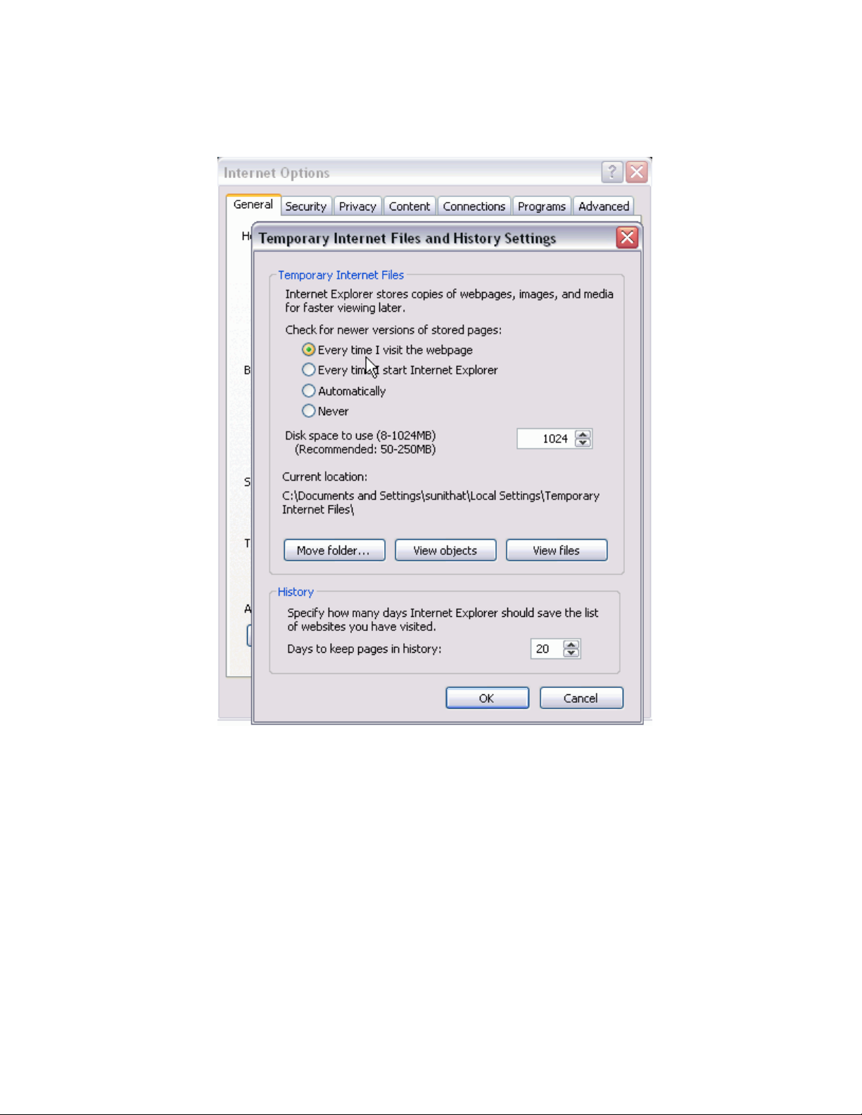
FIGURE 1 Configuring Internet Explorer
Deleting temporary Internet files used by Java applications
Deleting temporary Internet files used by Java applications
For Web Tools to operate correctly, you must delete the temporary Internet files used by Java
applications.
To delete these files, perform the following steps.
1. From the Control Panel, open Java.
2. Select the General tab and click Settings.
3. Click Delete Files to remove the temporary files used by Java applications.
4. Click OK on the confirmation dialog box.
You can clear the Trace and Log files check box if you want to keep those files.
5. Click OK.
6. On the Java Control Panel, click View to review the files that are in the Java cache.
Web Tools Administrator's Guide 25
53-1003169-01
Page 26

Java installation on the workstation
If you have deleted all the temporary files, the list is empty.
Java installation on the workstation
Java Plug-in must be installed on the workstation. If you attempt to open Web Tools without any Java
Plug-in installed:
• Internet Explorer automatically prompts and downloads the proper Java Plug-in.
• Firefox downloads the most recently released Java Plug-in.
If you attempt to open Web Tools with a later version of Java Plug-in installed:
• Internet Explorer might prompt for an upgrade, depending on the existing Java Plug-in version.
• Firefox uses the existing Java Plug-in.
Installing the JRE on your Solaris or Linux client workstation
To install JRE on your Solaris or Linux client workstation, perform the following steps.
1. Locate the JRE on the Internet, at the following URL:
http://www.oracle.com/technetwork/java/archive-139210.html
NOTE
This URL points to a non-Brocade website and is subject to change without notice.
2. On locating the JRE link, follow the instructions to install the JRE.
3. Create a symbolic link from this location:
$FIREFOX/plugins/libjavaplugin_oji.so
To this location:
$JRE/plugin/$ARCH/ns600/libjavaplugin_oji.so
Installing patches on Solaris
To install patches on Solaris, perform the following steps.
1. Search for any required patches for your current version of the JRE at the following website:
http://www.oracle.com/technetwork/java/javase/downloads/jre7u9-downloads-1859586.html
NOTE
This URL points to a non-Brocade website and is subject to change without notice.
2. Follow the link to download the patch.
3. Exit the browser when you have downloaded the patch.
4. Install the patch and restart the system.
26 Web Tools Administrator's Guide
53-1003169-01
Page 27

Installing the Java Plug-in on Windows
To Install the Java Plug-in on Windows, perform the following steps.
1. From the Start menu, select Control Panel and select the Java Control Panel.
2. Select the About tab.
3. Determine whether the correct Java Plug-in version is installed:
• If the correct version is installed, Web Tools is ready to use.
• If no Java Plug-in is installed, point the browser to a switch running Fabric OS 7.0.0 or later to
install JRE 1.7.0. Web Tools guides you through the steps to download the proper Java Plug-in.
• If an outdated version is currently installed, uninstall it, restart your computer, reopen the browser,
and enter the address of a switch running Fabric OS 7.0.0 or later to install JRE 1.7.0. Web Tools
guides you through the steps to download the proper Java Plug-in.
Java Plug-in configuration
If you are managing fabrics with more than 10 switches or 1000 ports, or if you are using the iSCSI
Gateway module extensively, you should increase the default heap size to 256 MB to avoid out-ofmemory errors.
If you are using a Mozilla family browser (Firefox, Netscape), you should set the default browser in the
Java Control Panel.
The following procedures instruct you in increasing the default heap size in the Java Control Panel and
in setting the default browser.
Installing the Java Plug-in on Windows
Enabling Java content in the browser
Launching Web Tools from a browser or Brocade Network Advisor is done using Java Web Start
technology. This requires the local system's web browser to be able to run Java web start applications.
This setting may have been turned off in the wake of recent Java zero-day vulnerabilities.
To turn on Java content in the browser, perform the following steps.
1. Launch Java Control Panel.
2. Click the Security tab and select the Enable Java content in the browser check box.
3. Click Apply.
When the Windows User Account Control (UAC) dialog box displays, allow permissions to make
the changes.
4. Click OK in the Java Plug-in confirmation window.
You can now enter the IP address of the switch and launch Web Tools from a browser.
Configuring the Java Plug-in for Windows
To configure Java Plug-in for Windows, perform the following steps.
1. From the Start menu, select Control Panel > Java.
2. Click the Java tab.
3. In the Java Applet Runtime Settings section, click View.
Web Tools Administrator's Guide 27
53-1003169-01
Page 28
Configuring the Java Plug-in for Mozilla family browsers
The Java Runtime Environment Settings dialog box displays.
4. Double-click the Runtime Parameters field and enter the following information to set the minimum
and maximum heap size:
-Xms256m -Xmx256m
In this example, the minimum and maximum sizes are both 256 MB.
5. Click OK to apply your settings and close the Java Control Panel.
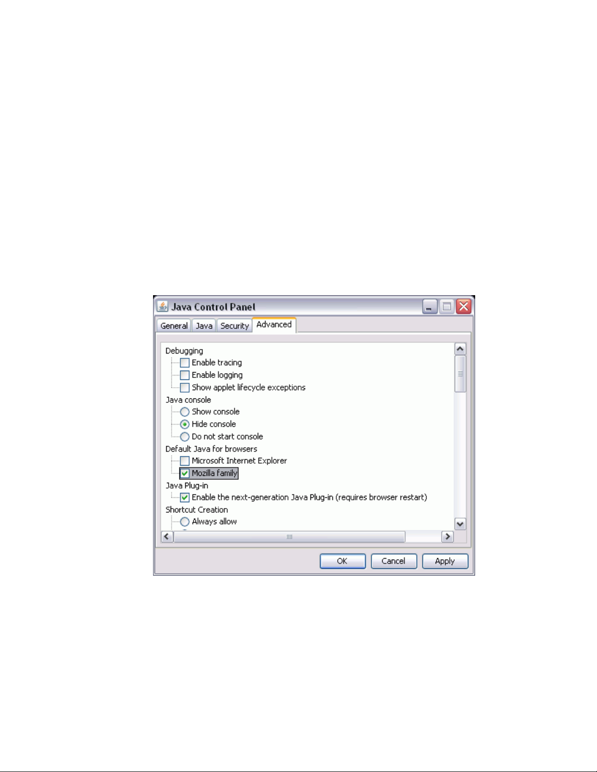
Configuring the Java Plug-in for Mozilla family browsers
To configure Java Plug-in for Mozilla family browsers, perform the following steps.
1. From the Start menu, select Control Panel.
2. Click the Advanced tab and expand the Default Java for browsers option, as shown in the
following figure.
FIGURE 2 Default Java for browsers option
3. Select Mozilla family and click Apply .
4. Click OK to apply your settings and close the Java Control Panel.
Value line licenses
If you open Web Tools on a switch with a limited license, and if the fabric exceeds the switch limit
indicated in the license, then Web Tools displays a warning message. Web Tools allows a 30-day
28 Web Tools Administrator's Guide
53-1003169-01
Page 29

grace period, during which you can still monitor the switch while continuing to display warning
messages periodically.
These messages warn you that your fabric size exceeds the supported switch configuration limit and
tells you how long you have before Web Tools is disabled. After the 30-day grace period, you are no
longer able to open Web Tools from the switch with the limited switch license.
Web Tools is part of the Fabric OS of a switch. When you open Web Tools on a switch, you can
manage other switches in the fabric that have earlier or later firmware versions. It is important to note
that when accessing these switches you are opening the remote switch’s version of Web Tools, and the
functionality available for those switches might vary.
Opening Web Tools
You can open Web Tools on any workstation with a compatible Web browser installed. For a list of Web
browsers compatible with Fabric OS v7.3.0, refer to System requirements on page 23. Web Tools
supports both HTTP and HTTPS.
To open Web Tools, perform the following steps.
1. Open the Web browser and enter the IP address of the device in the Address field, such as:
http://10.77.77.77
or
Opening Web Tools
https://10.77.77.77
2. Press Enter.
The Web Tools login dialog box displays. Refer to Logging in on page 29 for more information.
NOTE
If you are using Firefox, the browser window is left open. You can close it anytime after the login
dialog box displays. If you are using Internet Explorer, the browser window automatically closes
when the login dialog box displays.
NOTE
If you have installed EZSwitchSetup on your workstation, the EZSwitchSetup Switch Manager
displays the first time you access the device. EZSwitchSetup provides an easy-to-use wizard
interface that may be used to simplify the initial setup procedure for smaller switches. Refer to the
EZSwitchSetup Administrator’s Guide for information about the EZSwitchSetup interface. If you want
to use Web Tools instead of EZSwitchSetup, click Advanced Management in the lower-left corner of
the window to open the Web Tools interface. This guide describes only the Web Tools interface.
Logging in
When you use Web Tools, you must log in before you can view or modify any switch information. This
section describes the login process.
Prior to displaying the login window, Web Tools displays a security banner (if one is configured for your
switch), that you must accept before logging in. The security banner displays every time you access the
switch.
Web Tools Administrator's Guide 29
53-1003169-01
Page 30

Logging in to a Virtual Fabric
When you are presented with the login window, you must provide a user name and a password. Your
home Admin Domain is automatically selected. You can select to log in to an Admin Domain other
than your home domain.
NOTE
You must log in before you can view Switch Explorer (shown in Figure 4 on page 39).
Use this procedure to log in to the Admin Domain.
1. Click Run on the signed certificate applet.
A warning dialog box may display. If you select the check box Always trust content from this
publisher, the warning dialog box is not displayed when you open Web Tools again.
2. Click OK in the security banner window, if one displays.
3. In the login dialog box, enter your user name and password.
If your current password has expired, you must provide a new password and confirm the new
password.
Logging in to a Virtual Fabric
If you are logging in to a platform that is capable of supporting Virtual Fabrics, the login dialog box
provides the option of logging in to a Virtual Fabric. The following platforms support Virtual Fabrics:
• Brocade 7800
• Brocade 7840
• Brocade DCX and DCX-4S
• Brocade VA-40FC
• Brocade 6510
• Brocade 6520
• Brocade DCX 8510-8 and DCX 8510-4
• Brocade 5300
• Brocade 5100
• Brocade 5432
• Brocade 6548
To log in to a Virtual Fabric, perform the following steps.
1. Select Options to display the Virtual Fabric options.
You are given a choice between Home Logical Fabric and User Specified Logical Fabric as
shown in the following figure. Home Logical Fabric is the default.
30 Web Tools Administrator's Guide
53-1003169-01
Page 31

FIGURE 3 Virtual Fabric login option
Switching between Virtual Fabrics
2. Log in to a logical fabric.
• To log in to the home logical fabric, select Home Logical Fabric and click OK.
• To log in to a logical fabric other than the home logical fabric, select User Specified Logical
Fabric, enter the fabric ID number or the context name, and click OK.
On providing the context name, a dialog box displays with the available list of VF ID-Context Name
(role of the context). You can select the role from the list and log in.
Switching between Virtual Fabrics
To switch between one Virtual Fabric to another, perform the following steps.
1. Log in to Web Tools using the User Specified Logical Fabric option.
You can enter the context name to log in.
2. Select the context name you want to access from the Logical Switch list.
The base switch has Base appended in the context name.
3. Click Yes on the Switch Virtual Fabric Context confirmation dialog box.
4. Repeat step 2 and step 3 to switch to another Virtual Fabric.
Logging in to an Admin Domain
If you are logging in to a platform that is capable of supporting Admin Domains, the login dialog box
displays. You do not have an Admin Domain option if the Access Gateway mode is enabled. Admin
Domains and Virtual Fabrics are mutually exclusive.
1. Select Options to select an Admin Domain other than your default home domain.
You are given a choice of Home Domain (the default) or User Specified Domain.
2. Log in to an Admin Domain.
Web Tools Administrator's Guide 31
53-1003169-01
Page 32

Logging out
• To log in to the home domain, select Home Domain and click OK.
• To log in to an Admin Domain other than the home domain, select User Specified Domain,
enter the Admin Domain name or number, and click OK.
If the user name or password is incorrect, a dialog box displays indicating an authentication failure.
If you entered valid credentials, but specified an invalid Admin Domain, a dialog box displays from
which you can select a valid Admin Domain or click Cancel to log in to your home domain.
Logging out
You can end a Web Tools session either by selecting Manage > Exit, or by closing the Switch
Explorer window.
You might be logged out of a session involuntarily, without explicitly selecting the Manage > Exit,
under the following conditions:
• A physical fabric administrator changes the contents of your currently selected Admin Domain.
• Your currently selected Admin Domain is removed or invalidated.
• Your currently selected Admin Domain is removed from your Admin Domain list.
• You initiate a firmware download from the Web Tools Switch Administration window. In this case,
you are logged out a few minutes later when the switch restarts.
• Your session times out.
Role-Based Access Control
Role-Based Access Control (RBAC) defines the capabilities that a user account has based on the
assigned role. For each role, there is a set of predefined permissions on the jobs and tasks that can be
performed on a fabric and its associated fabric elements.
When you log in to a switch, your user account is associated with a predefined role. The role
determines the level of access you have on that switch and in the fabric. The following table describes
these roles.
For information about creating unique user account roles, refer to User-defined accounts on page
197.
Predefined Web Tools roles TABLE 5
Role Description
admin You have full access to all of the Web Tools features.
operator You can perform any actions on the switch that do not affect the stored configuration.
securityadmin You can perform actions that do not affect the stored configuration.
switchadmin You can perform all actions on the switch, except the following:
• You cannot modify zoning configurations.
• You cannot create new accounts.
• You cannot view or change account information for any accounts. You can only view your
own account and change your account password.
32 Web Tools Administrator's Guide
53-1003169-01
Page 33

Predefined Web Tools roles (Continued)TABLE 5
Role Description
zoneadmin You can only create and modify zones.
fabricadmin You can do everything the Admin role can do except create new users.
basicswitchadmin You have a subset of Admin level access.
user You have nonadministrative access and can perform tasks such as monitoring system activity.
Session management
A Web Tools session is the connection between the Web Tools client and its managed switch. A
session is established when you log in to a switch through Web Tools. When you close Switch Explorer,
Web Tools ends the session.
A session remains in effect until one of the following happens:
• You exit
• You close the Switch Explorer window
• The session ends due to inactivity (time out)
A session automatically ends if no information was sent to the switch for more than two hours. Because
user keystrokes are not sent to the switch until you apply or save the information, it is possible for your
session to end while you are entering information in the interface. For example, entering a zoning
scheme in the Zoning module does not require you to send information to the switch until you save the
scheme.
Web Tools does not display a warning when the session is about to time out. If your session ends due
to inactivity, all Web Tools windows become invalid and you must restart Web Tools and log in again.
Web Tools enables sessions to both secure and nonsecure switches.
Access rights for your session are determined by your role-based access rights and by the contents of
your selected Admin Domain. After you log in, you can change to a different Admin Domain at any time.
However, you cannot change your role-based permissions.
Session management
Ending a Web Tools session
To end a Web Tools session, perform one of the following actions:
• Select Manage > Exit.
• Click the X in the upper-right corner of the Switch Explorer window to close it.
• Close all open Web Tools windows.
Web Tools system logs
Web Tools uses the log4j framework to write the logs into a file.
Web Tools Administrator's Guide 33
53-1003169-01
Page 34

SupportSave logs
When you launch Web Tools for the first time, it automatically creates the following directories. These
directories are created under Web Tools directory if they are not available:
• A <Web Tools> directory under the user home directory.
• The Web Tools Switch Support Save directory with the name format <Core Switch Name-Switch IP
Address-Switch WWN>.
The Web Tools Switch Support Save directory contains the following files:
• Log4j.xml
• WebTools.log
• SwitchInfo.txt
The SwitchInfo.txt file contains the following basic switch information:
• Switch name
• Fabric OS version
• Switch type
• Ethernet IPv4
• Ethernet IPv4 subnet mask
• Ethernet IPv4 gateway
The maximum size of the webtools.log file is 5 MB. It is rolled into a new file when the 5 MB file size
limit is exceeded. A backup file named webtools1.log is automatically created. Web Tools maintains
only one webtools.log backup file at a time.
The Web Tools debug dialog box can be used to enable the debug state and level for a module at
runtime.
If you are familiar with XML scripting, you can edit the configuration file (log4j.xml) to collect the data at
startup. If you edit the configuration file, Web Tools need to be restarted. Contact your switch support
supplier for assistance.
SupportSave logs
Beginning with Fabric OS v7.1.0, Web Tools allows you to collect the following Web Tools-related
SupportSave data:
NOTE
Web Tools SupportSave collects logs for troubleshooting Web Tools. To collect switch logs, use the
SupportSave command through the Fabric OS CLI or the Technical Support feature in Brocade
Network Advisor.
• HTML files
• CAL files
• Web Tools logs folder
To collect SupportSave logs, perform the following steps.
1. Click Tools > SupportSave.
The SupportSave dialog box displays.
2. Click Browse to select the location where the SupportSave output must be saved.
34 Web Tools Administrator's Guide
53-1003169-01
Page 35

The default path for Windows is C:\Documents and Settings\<<user>>\Webtools\<log file>.
The default path for Linux is /root/WebTools/<switch log file>.
3. Click Capture to start collecting the SupportSave logs.
A zipped-up SupportSave folder is saved in the defined location. SupportSave zip file name format is
"WT-SS-switchIP-FID-dd-mm-yy-hh-mm-ss". The SupportSave file name will show the VF ID if VF is
enabled on the switch.
NOTE
SupportSave collection is terminated if the time exceeds 20 minutes.
Requirements for IPv6 support
The following list provides requirements for Web Tools IPv6 support:
• In a pure IPv6 environment, you must configure your DNS maps to the IPv6 address of the switch.
• The switch name is required to match the DNS name that is mapped to the IPv6 address.
• If both IPv4 and IPv6 addresses are configured, Web Tools can be launched using any configured IP
address.
Requirements for IPv6 support
Web Tools Administrator's Guide 35
53-1003169-01
Page 36

Requirements for IPv6 support
36 Web Tools Administrator's Guide
53-1003169-01
Page 37

Using the Web Tools Interface
● Viewing Switch Explorer..................................................................................................37
● Displaying tool tips.......................................................................................................... 45
● Right-click options........................................................................................................... 45
● Refresh rates...................................................................................................................46
● Displaying switches in the fabric..................................................................................... 47
● Recommendations for working with Web Tools.............................................................. 47
● Opening a Telnet or SSH client window..........................................................................48
● Collecting logs for troubleshooting.................................................................................. 48
Viewing Switch Explorer
The first thing you see when you log in to a switch with Web Tools is Switch Explorer, shown in the
following figure. Switch Explorer is divided into tabs and areas that provide access to, and information,
about the switch and fabric. The Switch Explorer areas are:
• Three tabs - Switch View, Port Admin, and Name Server.
If Access Gateway is enabled, the Access Gateway Devices tab displays instead of Name Server.
For more information, refer to Using the Access Gateway on page 175.
The Fabric Tree under Switch View displays a list of all the switches in the fabric.
• The menu bar, at the top of the window, provides access to the following tasks:
‐ Viewing tasks, such as the switch view, port administration, and name server.
‐ Configuration tasks, such as switch administration, zone administration, fabric watch, and
switch status policy.
‐ Monitoring tasks, such as performance monitoring, system monitoring, and viewing the
Web Tools Administrator's Guide
53-1003169-01
NOTE
You can manage basic zoning and Traffic Isolation zoning using Web Tools and Web Tools
with the Enhanced Group Management (EGM) license. To perform clone operations for
zoning, the EGM license must be installed on the switch; otherwise, access to this feature is
denied and an error message displays. You must use Brocade Network Advisor to print the
zone database summary configuration and to analyze zone configurations. For more
information on zoning management, refer to Zone configuration and zoning database
management on page 151.
power, temperature, or fan status.
NOTE
To perform monitoring tasks such as performance monitoring, the EGM license must be
installed on the switch; otherwise, access to this feature is denied and an error message
displays.
37
Page 38

Using the Web Tools Interface
‐ Reporting tasks, such as viewing the status of a switch.
‐ Tools tasks, such as opening the Telnet or SSH client window, beaconing a switch or
• The buttons below the menu bar provide access to switch information: status, temperature, power,
and fan data.
Although clicking a button can open a separate dialog box or window displaying the management
tasks, all access control is established when you first log in to the switch.
Buttons in Switch Explorer are unavailable for two reasons: because your account does not have
sufficient privileges to access this feature, or your currently selected Admin Domain does not meet
some condition to access the feature.
• The Switch View displays an interactive graphic of the switch.
• The Switch Events and Switch Information tabs allow you to view event information and switch
information, including connectivity, port, zone and other information.
• An indicator bar in the lower-right corner of every module window contains the Admin Domain you
are currently viewing, the current user name logged in to the switch, and the role associated with
that user account.
• The small right arrow near the Switch Event tab displays the switch. When you exit Web Tools, it
remembers the last window settings the next time you log in to the application. If you display the
switch, the next time you log in to Web Tools, by default the Switch View displays.
• Web Tools displays host time and switch time. The timestamp displayed in the Last polling refresh
time field in the lower-left corner of the window is the host time, in which the Web Tools is
launched. All other timestamp displayed in the application is the switch time. The following are the
features that display the host time.
‐ Port Admin tab
‐ Switch View tab
‐ Name Server tab
‐ FCR dialog
‐ Fabric Watch dialog
‐ System Monitoring dialog
‐ Netstat Performance dialog in Switch Admin tab
The EGM license is required only for 8 Gbps platforms, such as the following:
• Brocade Encryption Switch
• Brocade 300, 5300, 5100, and 5432 switches
• Brocade VA-40FC
• Brocade 7800
For non-8 Gbps platforms, all functionalities are available without the EGM license.
chassis, and access to SupportSave.
38 Web Tools Administrator's Guide
53-1003169-01
Page 39

FIGURE 4 Switch Explorer
Persisting GUI preferences
1. Menu bar
2. Switch View buttons
3. Tabs and Fabric Tree
4. Zoom in and Zoom out buttons
5. Switch View
6. Switch Events and Switch Information
7. Indicator bar
8. Professional Management Tool offering
9. Last polling refresh time - The host time in which Web Tools is launched
Persisting GUI preferences
Web Tools persists your GUI preferences across sessions for Switch Explorer, and the Port Admin,
Switch Admin, Name Server, and Zone Admin dialog boxes on all browser platforms. Persistence is
performed on a per-host basis.
If you launch Web Tools from Brocade Network Advisor (BNA), all of the Web Tools GUI persistence
data for each user name is stored in the BNA database.
The Port Admin GUI preferences that persist are:
• Basic or Advance mode
• Last selected tab by the user
• Table column sorting
• Table column positions
The Switch Admin GUI preferences that persist are:
• Basic or Advance mode
• Last selected tab
Web Tools Administrator's Guide 39
53-1003169-01
Page 40

Tabs
• Table column sorting
• Table column positions
The Switch Explorer GUI preferences that persist are:
• Last selected tab
The Name Server GUI preferences that persist are:
• Table column sorting
• Table column positions
The Zone Admin GUI preferences that persist are:
• Basic Zones
• Traffic Isolation Zones
• Last selected tab
• Table column sorting
• Table column positions
Tabs
Switch Explorer provides access to the following three tabs:
• Switch View
• Port Admin
• Name Server --This feature is available with Web Tools and Web Tools with the EGM license.
Name Server information is collected from the selected switch. Refer to "Displaying the Name
Server entries" on page 53 for more information.
Fabric Tree
Fabric Tree under Switch View displays all switches in the fabric, even those that do not have a Web
Tools license and that are not owned by your selected Admin Domain. Switches that are not owned by
the Admin Domain are shown in the Fabric Tree with switch status. Fabric Tree does not display
switches segmented before you opened Web Tools.
Only two types of switch icons display in Fabric Tree; one for a pizza box and one for a chassis. No
platform-based icons are supported.
Use the menu at the top of the Fabric Tree area to view switches in the Fabric Tree by switch name,
IP address, or WWN. You can rest the pointer over a switch to display the IP address, current status,
and other details of the switch. To manually refresh the status of a switch within the fabric, right-click
the switch in the Fabric Tree and select Refresh.
Although Fabric Tree displays all the switches in the fabric, you can manage switches that support
Fabric OS v6.1 and later versions because it does not require a Web Tools license. If a switch is
launched from Fabric Tree, preference will be given to IPv4, even though both IPv4 and IPv6 are
configured for that particular switch.
The versions earlier than Fabric OS v6.1 require a Web Tools license and, if applicable, an EGM
license installed. Other switches must be managed through the Fabric OS command line interface
(CLI), another management application, or by using Brocade Network Advisor.
40 Web Tools Administrator's Guide
53-1003169-01
Page 41

Changing the Admin Domain context
Changing the Admin Domain context
The Admin Domain field displays the currently selected Admin Domain and allows you to change to a
different one. The ability to change Admin Domain context requires that the EGM license is enabled on
the switch. Otherwise, an error message displays.
If you are logged in to Web Tools without the EGM license, you must log in again using a specific Admin
Domain.
After you log in, all Admin Domains assigned to you are available in the menu. For most administrative
tasks, you must be in either AD0 or the physical fabric.
When changing the Admin Domain context, the option for selecting AD from the list is not available if
the EGM license is not present.
To change the Admin Domain context, perform the following steps.
1. Select a domain from the Admin Domain menu.
2. Click OK in the confirmation window.
Switch Explorer refreshes to display the new Admin Domain context. You can monitor the progress
using the progress bar.
The system displays a list of all open windows. You can choose to change the Admin Domain, which
closes all the open windows, or cancel the action and return to Switch Explorer.
NOTE
The Telnet window and the Fabric Details are not AD-filtered and do not need to be closed.
Switch View buttons
The Switch View buttons let you access the following switch information:
• Status --Click the button to view the status of the switch.
• Temp --Click the button to view temperature monitors.
• Power --Click the button to view power supply information.
• Fan --Click the button to view the status of the switch fans.
NOTE
For all status displays based on errors per time interval, any errors cause the status to show faulty until
the entire sample interval has passed.
Switch View
You can click the small right arrow towards the left of the Switch Event tab to display the Switch View .
The Switch View displays a graphical representation of the switch, including a real-time view of switch
and port status. Refer to Figure 4 on page 39.
NOTE
Blades are graphically represented in the Web Tools GUI. They are vertical in the DCX, and horizontal
in the DCX-4S.
Web Tools Administrator's Guide 41
53-1003169-01
Page 42

Port representations
The default Switch View display refresh rate is 60 seconds. However, the initial display of Switch
Explorer may take from 30 to 60 seconds after the switch is booted. Refresh rates are fabric-size
dependent. The auto-refresh interval may not be less than 45 seconds. However, the refresh rate
varies depending on the activity in the fabric and on the host system you are using. The larger the
fabric, the longer it takes to poll the fabric and refresh the view. F_Port and L_Port connection
changes refresh immediately.
Port representations
The ports in the Switch View show the port type. Borders around the accessible ports indicate that
SFP modules are present. A colored border indicates the status of the port; for example, a green
border indicates that the port is connected and traffic is flowing. Ports that are not accessible do not
display the port type and do not have borders.
When you pause the pointer on a port, a yellow color toggling effect is available to identify the selected
port.
The port LEDs in the Switch View match the LEDs on the physical switch. However, the blink rate of
the LEDs in the Switch View does not necessarily match the blink rate of the LEDs on the physical
switch. Refer to Port LED interpretation on page 166 for more information.
Right-click a port in the Switch View to get a menu that opens the Port Admin tab, allowing you to
view detailed information about the port. From Port Admin, you can access information on all other
ports. Refer to Managing Ports on page 95 for more information.
NOTE
For detailed information on ISL Trunking, F_Port Trunking, and long distance, you must install the
EGM license on the switch; otherwise access to these features is denied and an error message is
displayed.
E_Ports are visible in all domains. For the Brocade DCX, the Port Admin view is launched for ICL
ports.
USB port representation
For switches with USB ports, the USB Storage Management view is launched for USB ports as
shown in the following figure.
42 Web Tools Administrator's Guide
53-1003169-01
Page 43

FIGURE 5 USB port storage management
Zoom in and zoom out
NOTE
Click the USB port on the Switch View to launch the USB Storage Management window.
Zoom in and zoom out
You can use the zoom buttons ( ) above the graphical Switch View to magnify the hardware
image. Click the zoom in button (+) to see an enlarged view of the switch and click the zoom out button
(-) to see the default view of the switch. You can pause the pointer over the zoom in button (+) and the
zoom out button (-) to view the tool tip.
Switch Events and Switch Information
Switch Events and Switch Information display as tab forms under Switch View. The Switch
Information tab is polled every 60 seconds and the Switch Events tab is polled every 15 seconds.
Both the tabs are polled based on the switch time.
Web Tools Administrator's Guide 43
53-1003169-01
Page 44

Using the Web Tools Interface
NOTE
You can click the column head to sort the events by a particular column, and drag the column divider
to resize a column. You can also right-click a column heading to resize one or all columns, sort the
information in ascending or descending order, or select which columns are displayed.
The Switch Information tab displays information about the following items:
• Last updated at: Displays the switch time.
• Switch
‐ Name: Name of the switch.
‐ Status: Status of the switch.
‐ Fabric OS Version: Fabric OS version of the switch.
‐ Domain ID: Domain ID of the switch.
‐ WWN: World Wide Name of the switch.
‐ Type: Type of the switch.
‐ Role: Role of the switch.
The following information is specific to Virtual Fabrics:
‐ Base Switch: Indicates whether the logical switch can act as a base switch.
‐ Default Switch: Indicates whether the logical switch is the default logical switch.
‐ Allow XISL Use: Indicates whether the logical switch is allowed to connect to other logical
• Ethernet
‐ Ethernet IPv4: Ethernet IPv4 address of the switch.
‐ Ethernet IPv4 netmask: Ethernet IPv4 subnet mask address of the switch.
‐ Ethernet IPv4 gateway: Ethernet IPv4 gateway address of the switch.
‐ Ethernet IPv6 : Ethernet IPv6 address of the switch.
• FC
‐ IPFC IPv4: Fiber Channel IPv4 address.
‐ IPFC IPv4 net mask: Fiber Channel IPv4 subnet mask address.
• Model Type
‐ Brocade DCX 8510-8 and DCX 8510-4: Model type value is 1.
‐ Brocade DCX and DCX-4S: Model type is not supported.
• Zone
‐ Effective Configuration: Indicates whether zone configuration is enabled or not.
• Other
‐ Manufacturer serial number: Displays the serial number of the manufacturer.
‐ Supplier serial number: Displays the serial number of the supplier.
‐ License ID: Displays the license ID.
• RNID
‐ Type: Type of the switch.
‐ Model: Model of the switch.
‐ Tag: Tag of the switch.
‐ Sequence number: Sequence number of the switch.
‐ Insistent Domain ID Mode: Current status of the Insistent Domain ID mode of the switch.
‐ Manufacturer: Manufacturer of the switch.
‐ Manufacturer Plant: Plant where the switch was manufactured.
switches using an extended inter-switch link (XISL).
44 Web Tools Administrator's Guide
53-1003169-01
Page 45

For more information, refer to Displaying switch information on page 161.
Free Professional Management tool
You can use the Professional Management tool with Web Tools to view connectivity for each fabric, to
back up and restore last-known configurations, and more. You can also use it with the Enhanced Group
Management (EGM) license to manage groups of switches, download firmware, manage security
settings, and deploy configurations across groups of switches. Contact your preferred storage supplier
to get a complimentary copy of the Professional Management tool.
Launch the install wizard for the free Professional Management tool through the link located at the
bottom of the Switch Explorer window.
Displaying tool tips
When you pause the pointer over a Web Tools button, the system displays a brief description of the
button. If you pause the pointer over most components, the system displays tool tip information about
the component.
In the Fabric Tree, you can pause the pointer over a switch to view its type, subtype, name, Ethernet
IPv4 and IPv6 addresses, IPFC, and status of the switch.
In Switch View, you can pause the pointer over a blade to view the blade ID and its status. It is easier
to use the top of the blade to display the tool tip so that you do not inadvertently display the port tool
tips. You can select a port and pause the pointer over the Zoom In and Zoom Out buttons to see an
enlarged view or the default view of the switch. Firmware versions and IP addressing are displayed for
CP blades.
When you pause the pointer over a port, you can view the:
• Port name
• Port ID
• Port beacon
• Port number
• Port index
• Port type (E_Port, F_Port, L_Port, D_Port, EX_Port, GigE port, or U_Port)
• Port status (online or offline)
• Port state (in-sync, no_sync, no light, or no module)
Free Professional Management tool
Right-click options
You can right-click a port to quickly perform some basic port administration tasks, as shown in the
following figure.
Web Tools Administrator's Guide 45
53-1003169-01
Page 46

Refresh rates
FIGURE 6 Right-click menu for ports (from Switch Explorer)
The tasks are:
• The Port Admin option displays the Port Admin tab.
• The Port Details option displays read-only information about a port, without opening the Port
Admin tab. You can right-click on the table content to export or copy the information from the Port
Details window.
• The Configure option provides another menu of options to allow you to rename, enable, and
disable ports, and to set persistent enable or disable without opening the Port Admin tab.
Refresh rates
The refresh, or polling, rates listed in this section and throughout the book indicate the time between
the end of one polling period and the start of the next, and not how often the screen is refreshed. A
refresh rate of 60 seconds does not ensure that a refresh occurs every 60 seconds. It ensures that the
time between each refresh activity is no more than 60 seconds.
Auto-refresh intervals might be not be exactly 60 seconds. The refresh rate varies depending on the
activity in the fabric and on the host system you are using. Following are some variables you should
consider when refreshing the fabric:
• Refresh Now button is disabled for 6-8 seconds on every click.
• Retrieval time increases when you are in a large fabric because there is more data to retrieve from
the switches.
• Processor speed of the system you are using may slow down the refresh rate.
• OS-Job Scheduling if you are using a host system in the data center impacts the refresh rate.
• JVM-Performance can contribute to causing interval differences between what is on-screen and
how long it is actually taking.
For these reasons, the time displayed in the port statistics tab might not be refreshed as expected.
The counter time indicates only that "this statistics data is retrieved from the switch in this time period."
To ensure the correct information, the time field is updated along with the port statistics data after
every refresh.
The refresh rates are different for each module. The following table lists polling rates by module.
Though these rates are sample rates, they correctly illustrate variance in the refresh rates throughout
Web Tools.
TABLE 6
Module Polling rate
Name Server User-defined; 45 sec minimum
46 Web Tools Administrator's Guide
Polling rates
53-1003169-01
Page 47

Polling rates (Continued)TABLE 6
Module Polling rate
Zoning Database 60 sec
Fabric Watch 45 sec
Performance Monitor (This feature requires the EGM license.) 30 sec
Port Management User-defined; 45 sec minimum
FC Routing 45-90 sec, depending on network traffic
Displaying switches in the fabric
If your fabric has more than one switch, you can open Web Tools from one switch and then access
other switches. You can also launch Web Tools from the Brocade Network Advisor client as Element
Manager. This lets you manage Web Tool requests where the fabric is in a private network.
Launch Web Tools from Brocade Network Advisor if you need to access the fabric from a host that is
not in the same network and does not have direct access to the fabric.
Displaying switches in the fabric
NOTE
If you open switches, running Fabric OS v4.4.x or later, from a Fabric Tree displayed for a version
earlier than a v4.4.x switch, some of the features might be disabled.
To display switches in the fabric, perform the following steps.
1. Open Web Tools as described in "Opening Web Tools" on page 10 and log in to the switch.
2. If the Fabric Tree is not expanded, click the plus sign (+) in the Fabric Tree to view all the switches
in the fabric.
3. Click a switch in the Fabric Tree.
A separate browser dialog box displays the selected switch.
The graphic of the selected switch displays in Switch View. Additional switch information displays in
the Switch Events and Switch Information tabs.
Recommendations for working with Web Tools
Brocades makes the following recommendations for working with Web Tools:
• If you receive an error when saving changes in the Switch Administration window, note the error
messages, refresh the window, and make your changes again. Do not continue making changes
without refreshing the window and determining which changes were saved correctly.
• In a fabric containing switches and directors running different versions of firmware, use the switches
or directors with the latest firmware versions to control the fabric.
• If switches are accessed simultaneously from different connections (for example, Web Tools, CLI,
and API), changes from one connection might not be updated to the other, and some modifications
Web Tools Administrator's Guide 47
53-1003169-01
Page 48

Opening a Telnet or SSH client window
might be lost. Make sure that, when you connect with simultaneous multiple connections, you do
not overwrite the work of another connection.
• Several tasks in Web Tools make fabric-level changes, such as the tasks in Zone Administration.
When executing fabric-level configuration tasks, wait until you have received confirmation that the
changes are implemented before executing any subsequent tasks. For a large fabric, this can take
several minutes.
• Some data collection and processing operations in the iSCSI Gateway module might take a long
time to complete, especially in large fabrics or fabrics with large numbers of defined Discovery
Domains and Discovery Domain Sets. In most cases, progress bars are provided. Allow the
application a sufficient amount of time (30-40 seconds) to collect and display data before taking any
action or assuming the application is "hanging."
• A maximum of five simultaneous HTTP sessions to any one switch is recommended. An HTTP
session is considered a Brocade Network Advisor or Web Tools connection to the switch.
Opening a Telnet or SSH client window
When you open a Telnet or SSH client window, it connects to the IP interface of the switch. You
cannot connect to a CP blade on a director switch through a Telnet or SSH client window opened from
Web Tools, even when the blade has an IP address and supports Telnet sessions. Refer to the Fabric
OS Command Reference for information about the Telnet commands.
NOTE
Internet Explorer 10.0/11.0 default settings disable Telnet functionality. If you are using Internet
Explorer 10.0/11.0, you must make the appropriate changes in the registry to open the Telnet window.
To open a Telnet or SSH client window, perform the following steps.
1. Select a switch in Fabric Tree.
You are prompted to log in. The selected switch displays in Switch View.
2. Select Telnet/SSH Client under Tools menu. The Preference Dialog dialog box displays.
3. Select the client by clicking Telnet or SSH.
4. Enter the Telnet or SSH path, as defined for your implementation.
To avoid the need to remember and enter in the path, you can store the path on your PC and
browse to the location. Clicking the button to the right of the field initiates the browse capability.
5. Click OK.
The Telnet or SSH window displays.
6. Enter your user credentials at the login prompt.
7. To close the session, enter exit at the prompt and press the Enter key.
Collecting logs for troubleshooting
If you encounter problems using the Web Tools interface, collect Java logs for use in troubleshooting.
From Microsoft Windows, perform this procedure.
1. Open the Control Panel and select Java.
2. Click the Advanced tab.
48 Web Tools Administrator's Guide
53-1003169-01
Page 49

Using the Web Tools Interface
3. Expand the Java console.
4. Select Show console.
5. Restart Web Tools.
The Java console displays, along with the Web Tools opening page.
6. Perform the Web Tools operation that caused the problem.
7. Collect the logs shown on the Java console.
8. If you no longer want to see the Java console when you start Web Tools, go back to the Control
Panel, repeat steps 1 and 2, and then deselect Show console.
Web Tools Administrator's Guide 49
53-1003169-01
Page 50

Collecting logs for troubleshooting
50 Web Tools Administrator's Guide
53-1003169-01
Page 51

Managing Fabrics and Switches
● Fabric and switch management overview....................................................................... 51
● Configuring IP and subnet mask information.................................................................. 53
● Configuring Netstat Auto Refresh................................................................................... 54
● Configuring a syslog IP address..................................................................................... 54
● Removing a syslog IP address........................................................................................55
● Configuring IP filtering.....................................................................................................55
● Blade management......................................................................................................... 56
● Switch configuration........................................................................................................ 58
● Switch restart.................................................................................................................. 61
● System configuration parameters................................................................................... 62
● Licensed feature management........................................................................................67
● High Availability overview................................................................................................69
● Event monitoring............................................................................................................. 71
● Displaying the Name Server entries................................................................................74
● Physically locating a switch using beaconing..................................................................75
● Locating logical switches using chassis beaconing........................................................ 75
● Virtual Fabrics overview.................................................................................................. 76
Fabric and switch management overview
Most of the management tasks described in this chapter are accessed through the Switch
Administration window. Information in the Switch Administration window is retrieved from the
selected switch, as shown in the following figure.
If the switch is not a member of the selected Admin Domain, most tabs in the Switch Administration
window display in read-only mode, regardless of your permission level. The User tab is editable
because most of its information does not require switch membership in the current Admin Domain.
Web Tools Administrator's Guide
53-1003169-01
51
Page 52

Opening the Switch Administration window
FIGURE 7 Switch Administration window, Switch tab, Basic mode
With the exception of switch time, information displayed in the Switch Administration window is not
updated automatically by Web Tools. To update the information displayed in the Switch
Administration window, click the Refresh button.
ATTENTION
Most changes you make in the Switch Administration window are buffered, and are not applied to
the switch until you save the changes. If you close the Switch Administration window without saving
your changes, your changes are lost. To save the buffered changes you make in the Switch
Administration window to the switch, click Apply before closing the module or before switching to
another tab. The License tab, Firmware Download tab, and the Security Policies tab are
exceptions. The changes you make on these tabs take effect immediately and there is no Apply
button. There is an Apply button in all the subtabs of security policies except ACL.
You can also use Telnet commands to perform management tasks. Refer to "Opening a Telnet or SSH
client window" on page 28 for information on how to launch a Telnet window using Web Tools.
Opening the Switch Administration window
Most of the management procedures in this chapter are performed from the Switch Administration
window.
To open the Switch Administration window, perform the following steps.
52 Web Tools Administrator's Guide
53-1003169-01
Page 53

Configuring IP and subnet mask information
1. Click Configure > Switch Admin.
The Switch Administration window displays in basic mode, as shown in Figure 7 on page 52. The
basic mode displays the "basic" tabs and options.
2. Click Show Advanced Mode to see all the available tabs and options, as shown in the following
figure.
FIGURE 8 Switch Administration window, Switch tab, Advanced mode
Configuring IP and subnet mask information
Before proceeding, collect all the information you need to configure the Ethernet IP interface. This
includes the subnet mask, gateway IP address, or IPFC, and subnet mask for your system. When you
configure or change the Ethernet IP, subnet mask, gateway IP, or IPFC, and subnet mask from Web
Tools, there is a normal loss of network connection to the switch. Close all current windows and restart
Web Tools with the new IP address.
NOTE
The IPFC address is specific for each logical switch. The IPFC address is set to FC0 for switches that
do not support Virtual Fabrics.
Web Tools Administrator's Guide 53
53-1003169-01
Page 54

Configuring Netstat Auto Refresh
To configure the IP and subnet mask information, perform the following steps.
1. Select the Network tab.
2. In the appropriate IP address section, enter the IP address you want to use for the IP interface.
Use the IPv4 Address section or the IPv6 Address section to specify IP addresses.
3. In the IPv4 Address section:
• In the Ethernet IP field, enter the Ethernet IP address.
• In the IPFC Net IP field, enter the IPFC net IP address.
• In the Ethernet Mask field, enter the Ethernet mask address.
• In the IPFC Net Mask field, enter the IPFC net mask address.
• In the Gateway IP field, enter the gateway IP address.
4. In the IPv6 Address section, in the Ethernet IPv6 field, enter the Ethernet IP address.
5. You can also enable automatic configuration of IPv6 addresses by selecting Enable IPv6 Auto
Configuration.
The automatically generated IPv6 addresses are displayed under Auto Configured IPv6
Addresses. Eight auto-configured addresses are created per switch, and up to 24 for a DCX, or
DCX-4S chassis (eight per chassis, and eight per each installed CP).
Configuring Netstat Auto Refresh
The Netstat Performance window displays the details about Ethernet management port statistics such
as the Interface, MTU, Met, RX-OK, RX-ERR, RX-DRP, RX-OVR, TX-OK, TX-ERR, TX-DRP, TXOVR, and Flag.
To configure Auto Refresh, perform the following steps.
1. Open the Switch Administration window as described in Opening the Switch Administration
window on page 52.
2. Select the Network tab.
3. Click Netstat Performance.
4. Select the Auto Refresh check box to automatically refresh the port details.
Clear the check box to disable auto refresh.
5. When enabled, enter the interval time in seconds in the Auto-Refresh Interval field.
The port details are automatically refreshed, based on the configured time interval. The minimum
value is 15 seconds.
Configuring a syslog IP address
The syslog IP address represents the IP address of the server that is running the syslog process. The
syslog daemon reads and forwards system messages to the appropriate log files or users, depending
on the system configuration. When one or more IP addresses are configured, the switch forwards all
error log entries to the syslog on the specified servers. Up to six servers are supported. Refer to the
Fabric OS Administrator's Guide for more information on configuring the syslog daemon.
To configure a syslog IP address, perform the following steps.
54 Web Tools Administrator's Guide
53-1003169-01
Page 55

1. Open the Switch Administration window as described in Opening the Switch Administration window
on page 52.
2. Select the Network tab.
3. In the Syslog IP’s Configuration section, in the New IP field, enter an IP address in either IPv4 or
IPv6 format.
4. Click Add.
The new IP address displays in the Syslog IP area.
5. Click Apply.
Removing a syslog IP address
To remove a syslog IP address, perform the following steps.
1. Open the Switch Administration window as described in Opening the Switch Administration window
on page 52.
2. Select the Network tab.
3. Select a syslog IP address in the table and click Remove.
You can click Clear All to remove all of the syslog IP address from the table.
4. Click Apply.
Removing a syslog IP address
Configuring IP filtering
Web Tools provides the ability to control what client IP addresses may connect to a switch or fabric.
To set up IP filtering, perform the following steps.
1. Open the Switch Administration window (in Basic mode) as described in Opening the Switch
Administration window on page 52.
2. Click Show Advanced Mode.
3. Select the Security Policies tab.
4. Select IP Filter on the Security Policies menu.
5. Click Create Policy.
The Create IP Filter Policy dialog box displays.
6. Enter a policy name, select a policy type, and then click the Add Rule button.
7. Enter the rule order, rule type, source and destination IP addresses, and then modify the service or
destination port, protocol, and action as necessary.
Both the source and destination IP addresses are needed for the FWD rule type.
Only the source IP address is needed for the INPUT rule type, as the destination IP address field is
disabled.
8. Click OK.
After you create a policy, you can use the following controls on this tab to manage the policies:
• The Edit Policy button lets you select an existing policy and make changes to it.
• The Show Policy button lets you view the details of the policy in a read-only window.
• The Delete Policy button lets you delete a policy.
Web Tools Administrator's Guide 55
53-1003169-01
Page 56

Blade management
• The Clone Policy button lets you copy a policy. Use this feature when you want to create similar
policies. After you create a clone, you can edit the policy to make the appropriate changes.
• The Activate Policy button lets you make an existing policy active.
• The Distribute Policy button lets you distribute a policy to various switches.
• The Accepts Distribution check box lets you set the policy to accept or reject distributions.
Blade management
Web Tools provides the ability to enable and disable blades, and to set slot-level IP addresses for
blades. The procedure in this section applies only to the Brocade DCX 8510-4, Brocade DCX 8510-8,
or the Brocade DCX, DCX-4S enterprise-class platforms.
Enabling or disabling a blade
The Firmware Version columns display the firmware loaded onto each blade. A blade can have more
than one firmware image loaded onto it. The Blade State column in the Blade tab pane indicates
whether the blade is enabled.
NOTE
The blade state is always shown as enabled, even if you perform a blade disable operation. When a
blade is set to a disable state, only the ports on the blade are disabled. The blade remains active.
To enable or disable a blade, perform the following steps.
1. Open the Switch Administration window as described in Opening the Switch Administration
window on page 52
2. Select the Blade tab.
56 Web Tools Administrator's Guide
53-1003169-01
Page 57

FIGURE 9 Blade tab
Setting a slot-level IP address
3. Select Blade Action > Enable Blade for each blade you want to enable, or Blade Action >
Disable Blade to disable a blade, and click Yes in the confirmation dialog box.
Disabling a blade does not turn off the blade, it disables the ports on the blade. You cannot enable or
disable the CP blades.
Setting a slot-level IP address
To set an IP address, perform the following steps.
1. Open the Switch Administration window as described in Opening the Switch Administration window
on page 52.
2. Select the Blade tab.
3. Click Set IP address.
4. Select a slot number from the list.
5. Enter the IP address, subnet mask, and Gateway IP address.
6. Select a type from the list.
7. Click Add to add the new entry to the table.
When you click Add, the values remain in the fields. The Clear Gateway and Clear IP buttons are
available for clearing fields in the table.
Web Tools Administrator's Guide 57
53-1003169-01
Page 58

Viewing IP addresses
NOTE
To remove a configuration, select a row in the table and click Delete.
8. Click Apply to save the values currently shown in the table or click Cancel to close the dialog box
without saving any of your changes.
9. To update the switch with your changes, update the table using the Add and Delete buttons, and
then click Apply.
Viewing IP addresses
If you want to view the IP addresses configured on the switch for the currently populated slots, use the
Show IP Address button.
Use this procedure to display the IP addresses.
1. Open the Switch Administration window as described in Opening the Switch Administration
window on page 52.
2. Select the Blade tab.
3. Click Show IP Address.
4. Scroll through the list to view all the information.
5. When you are finished, click Close.
Switch configuration
Use the Switch tab of the Switch Administration window to perform basic switch configuration.
Figure 7 on page 52 displays an example of the Switch tab.
Enabling and disabling a switch
You can identify whether a switch is enabled or disabled in the Switch Administration window by
looking at the lower-right corner. If you pause the pointer over the icon, the system displays text that
indicates the status of the switch.
Use this procedure to enable or disable a switch.
1. Open the Switch Administration window as described in Opening the Switch Administration
window on page 52.
2. Select the Switch tab.
3. In the Switch Status section, click Enable to enable the switch or Disable to disable the switch.
4. Click Apply.
The system displays a confirmation window that asks if you want to save the changes to the switch.
You must click Yes to save the changes.
Enabling and disabling switch persistent
Use this procedure to enable or disable switch persistent. By default, switch persistent is disabled.
58 Web Tools Administrator's Guide
53-1003169-01
Page 59

Changing the switch name
1. Open the Switch Administration window as described in Opening the Switch Administration window
on page 52.
2. Select the Switch tab.
3. In the Switch Persistent section, do one of the following:
• Click Enable to enable the switch persistent.
• Click Disable switch immediately to disable the switch persistent immediately.
• Click Disable when the switch reboots to set the switch persistent in the disabled state and
disable switch persistent on reboot.
The switch remains in the enabled or temporarily online state until it reboots. After reboot, the
switch goes to the disabled state.
4. Click Apply.
The system displays a confirmation window that asks if you want to save the changes to the switch.
You must click Yes to save the changes.
Changing the switch name
Switches can be identified by IP address, domain ID, World Wide Name (WWN), or switch names.
Names must begin with an alphabetic character, but otherwise can consist of alphanumeric, hyphen,
and underscore characters. The maximum number of characters is 30, unless FICON mode is enabled.
When FICON mode is enabled, the maximum number of characters is 24.
NOTE
Some system messages identify a switch service by the chassis name. If you assign meaningful
chassis names and switch names, system logs are easier to use.
1. Open the Switch Administration window as described in Opening the Switch Administration window
on page 52.
2. Select the Switch tab.
3. Enter a new name in the Name field and click Apply.
Changing the switch domain ID
Although domain IDs are assigned dynamically when a switch is enabled, you can request a specific ID
to resolve a domain ID conflict when you merge fabrics.
To change the switch domain ID, perform the following steps.
1. Open the Switch Administration window as described in Opening the Switch Administration window
on page 52.
2. Disable the switch, as described in Enabling and disabling a switch on page 58.
3. Select the Switch tab.
4. Enter a new domain ID in the Domain ID field.
For IM0 (Brocade Native mode), the range of valid values is from 1 through 239.
5. Click Apply.
6. Enable the switch, as described in Enabling and disabling a switch on page 58.
Web Tools Administrator's Guide 59
53-1003169-01
Page 60

Viewing and printing a switch report
Viewing and printing a switch report
The switch report includes the following information:
• A list of switches in the fabric
• Switch configuration parameters
• A list of ISLs and ports
• Name Server information
• Zoning information
• SFP serial ID information
To view or print a report, perform the following steps.
1. Open the Switch Administration window as described in Opening the Switch Administration
window on page 52.
2. Select the Switch tab.
3. Click View Report.
4. In the new window that displays the report, view or print the report using your browser.
Setting a principal switch
To set the preference to a switch to become the next principal switch in the fabric, perform the
following steps.
NOTE
Principal switch selection is not supported in Access Gateway mode.
1. Open the Switch Administration window as described in Opening the Switch Administration
window on page 52.
2. Select the Switch tab.
3. In the Principal Switch section, perform one of the following actions to set the switch as a principal
switch:
• Select Set as preferred Principal Switch - The switch is set as the principal switch in the next
fabric rebuild.
• Select Set as preferred Principal Switch and then select Rebuild Fabric after setting
preferred principal switch - The switch is set as the preferred principal switch with rebuild
triggered forcefully.
• Select Set as preferred Principal Switch and enter the priority value in a range from 1 through
FF in the Priority field.
You can change the priority value and select the Rebuild Fabric after setting preferred principal
switch option from a principal or a subordinate switch. The principal switch selection is based on
the factors in the following table.
Principal switch selection factorsTABLE 7
Priority value with force
option
Subordinate switch Lesser than principal Fabric rebuild occurs and the switch comes up as a
Greater than principal Fabric rebuild occurs and the switch remains as a
60 Web Tools Administrator's Guide
Expected behavior
principal switch.
subordinate switch.
53-1003169-01
Page 61

Switch restart
Principal switch selection factors (Continued)TABLE 7
4. Click Apply.
Switch restart
When you restart the switch, the restart takes effect immediately. Ensure that there is no traffic or other
management on the switch, because traffic is interrupted during the restart; however, frames are not
dropped. Be sure to save your changes before the restart, because any changes not saved are lost.
Priority value with force
option
Equal to principal Fabric rebuild occurs and the principal switch is selected
Principal switch Lesser than subordinate No fabric rebuild, the switch remains principal.
Greater than subordinate Fabric rebuild occurs and the switch becomes
Equal to subordinate Fabric rebuild occurs and the principal switch is selected
Expected behavior
based on the WWN check (lower becomes principal
switch).
subordinate.
based on the WWN check (lower becomes principal
switch).
Performing a fast boot
A fast boot reduces boot time significantly by bypassing the power-on self-test (POST).
To perform a fast boot, perform the following steps.
1. Open the Switch Administration window as described in Opening the Switch Administration window
on page 52.
2. Click Fastboot.
3. On the Fastboot Confirmation window, click Yes to continue.
4. Click Apply.
Performing a reboot
To reboot the CP and execute the normal power-on booting sequence, perform the following steps.
1. Open the Switch Administration window as described in Opening the Switch Administration window
on page 52.
2. Click Reboot.
3. On the Reboot Confirmation window, click Yes to continue.
4. Click Apply.
Web Tools Administrator's Guide 61
53-1003169-01
Page 62

System configuration parameters
System configuration parameters
You must disable the switch before you can configure fabric parameters.
You can change the following system configuration parameters:
• Switch fabric settings
• Virtual channel settings
• Arbitrated loop parameters
• System services
• CSCTL QoS mode settings
• Signed firmware
WWN-based persistent PID assignment
WWN-based PID assignment allows you to configure a PID persistently using a device’s WWN. When
the device logs in to the switch, the PID is bound to the device WWN. If the device is moved to another
port in the same switch, or a new blade is hot-plugged, the device receives the same PID (area) at its
next login. For information on configuring WWN-based PID assignment, refer to Configuring fabric
settings on page 63.
This feature is deactivated by default. When the feature is enabled, bindings are created dynamically;
as new devices log in, they automatically enter the WWN-based PID database. The bindings exist until
you explicitly unbind the mappings through the CLI or change to a different addressing mode. If there
are any existing devices when you enable the feature, you must manually enter the WWN-based PID
assignments through the CLI.
Once WWN-based PID assignment is enabled, you must manually enter the WWN-based PID
assignments through the CLI for any existing devices. Any new devices logging in are automatically
entered in the WWN-based PID database. Current WWN-based PID bindings are cleared when you
change to a different addressing mode.
PID assignments are supported for a maximum of 4096 devices; this includes both point-to-point and
NPIV devices. The number of point-to-point devices supported depends directly on the areas
available. For example, 448 are available on an enterprise-class platform and 256 are available on
switches. When the number of entries in the WWN-based PID database reaches the number 4096 or
areas are used up, the oldest unused entry is purged from the database to free up the reserved area
for the new FLOGI. Refer to the following table for complete information.
Switches that support WWN-based persistent PID on Web ToolsTABLE 8
Platform VF Default switch Logical
DCX/DCX-4S
DCX 8510-4
DCX 8510-8
62 Web Tools Administrator's Guide
Enabled
Yes, if dynamic area
addressing is enabled
in the default switch.
switch
Yes
Area mode FICON mode
0 If 8-bit dynamic
mode is enabled,
FMS is not supported
1 Can be set
2 Not supported
53-1003169-01
Page 63

Configuring fabric settings
Switches that support WWN-based persistent PID on Web Tools (Continued)TABLE 8
Platform VF Default switch Logical
Brocade 5100
Brocade 5300
Brocade VA-40FC
Brocade 6510
Brocade 6520
Brocade 7800
Brocade 7840
Brocade 300
Brocade 5100
Brocade 5300
Brocade VA-40FC
Brocade 6510
Brocade 6520
Brocade 7800
Brocade 7840
Enabled Yes Yes Default-8 bit
Disabled N/A N/A Default-8bit
switch
Area mode FICON mode
Configurable
dynamic
Configurable
dynamic
Configuring fabric settings
To configure the fabric settings, perform the following steps.
1. Open the Switch Administration window as described in Opening the Switch Administration window
on page 52
2. Click Show Advanced Mode.
3. Select the Configure tab.
4. Select the Fabric subtab.
5. Make the fabric parameter configuration changes.
6. Click Apply.
7. Enable the switch as described in Enabling and disabling a switch on page 58.
Fabric settings
Configure the following fabric settings on the Fabric subtab of the Configure tab:
Fabric settingsTABLE 9
BB Credit The buffer-to-buffer credit is the number of buffers available to attached devices for frame
R_A_TOV Resource allocation timeout value (in milliseconds). This variable works with the E_D_TOV
receipt. The default BB Credit is 16. The range of valid values is from 1 through 27.
to determine switch actions when presented with an error condition. The default is 10000.
The possible range is (2*E_D_TOV) -120000. Values must be multiples of 1000.
Web Tools Administrator's Guide 63
53-1003169-01
Page 64

Enabling insistent domain ID mode
Fabric settings (Continued)TABLE 9
E_D_TOV Error detect timeout value (in milliseconds). This timer is used to flag a potential error
Datafield size The largest possible data field size (in bytes). The range of valid values is from 256 through
Address mode Displays the addressing mode present in the switch.
Sequence Level
Switching
Disable Device
Probing
Per-Frame Routing
Priority
Suppress Class F
Traffic
Insistent Domain ID
Mode
condition when an expected response is not received within the set time. The valid range is
1000 - (R_A_TOV/2)
2112.
Select this check box to enable frames of the same sequence from a particular group to be
transmitted together. When this option is not selected, frames are transmitted interleaved
among multiple sequences. Under normal circumstances, sequence-level switching should
be disabled for better performance. However, some host adapters have issues when
receiving interleaved frames among multiple sequences.
Set this mode only if the switch N_Port discovery process (PLOGI, PRLI, INQUIRY) causes
an attached device to fail. When set, devices that do not register with the Name Server are
not present in the Name Server database.
Select whether to select per-frame routing priority. When enabled, the virtual channel ID is
used in conjunction with a frame header to form the final virtual channel ID.
Applies only if VC-encoded address mode is also set. When selected, translative addressing
(which allows private devices to communicate with public devices) is disabled.
Set this mode to make the current domain ID insistent across reboots, power cycles, and
failovers. This mode is required fabric-wide to transmit FICON data.
WWN-based
Persistent PID
Set this mode to configure a PID persistently using a device’s WWN. When the device logs in
to the switch, the PID is bound to the device WWN. Refer to WWN-based persistent PID
assignment on page 62.
Enabling insistent domain ID mode
To enable insistent domain ID mode, perform the following steps.
1. Open the Switch Administration window as described in Opening the Switch Administration
window on page 52.
2. Disable the switch as described in Enabling and disabling a switch on page 58.
3. Select the Configure tab.
4. Select the Fabric subtab.
5. Select the Insistent Domain ID Mode check box.
6. Click Apply.
7. Enable the switch as described in Enabling and disabling a switch on page 58.
Configuring virtual channel settings
You can configure parameters for eight virtual channels (VCs) to enable fine-tuning for a specific
application. You cannot modify the first two virtual channels because these are reserved for switch
internal functions.
64 Web Tools Administrator's Guide
53-1003169-01
Page 65

Configuring arbitrated loop parameters
ATTENTION
The default virtual channel settings are already optimized for switch performance. Changing the default
values can improve switch performance, but can also degrade performance. Do not change these
settings without fully understanding the effects of the changes.
VC Priority specifies the class of frame traffic given priority for a virtual channel.
To configure the virtual channel settings, perform the following steps.
1. Open the Switch Administration window as described in Opening the Switch Administration window
on page 52
2. Disable the switch as described in Enabling and disabling a switch on page 58.
3. Select the Configure tab.
4. Select the Virtual Channel subtab.
5. Enter a value in the VC Priority field you want to change.
The only valid numeric values for all fields are either "2" or "3".
6. Click Apply.
7. Enable the switch as described in Enabling and disabling a switch on page 58.
Configuring arbitrated loop parameters
To configure arbitrated loop parameters, perform the following steps.
1. Open the Switch Administration window as described in Opening the Switch Administration window
on page 52.
2. Disable the switch as described in Enabling and disabling a switch on page 58.
3. Select the Configure tab.
4. Select the Arbitrated Loop subtab.
5. Select or clear the check boxes to enable or disable the corresponding arbitrated loop parameters.
6. Click Apply.
7. Enable the switch as described in Enabling and disabling a switch on page 58.
Arbitrated loop parameters
Configure the following arbitrated loop parameters on the Arbitrated Loop subtab of the Configure
tab.
Arbitrated loop parametersTABLE 10
Send Fan Frames Select this check box to specify that fabric address notification (FAN) frames are sent to
Always Send
RSCN
public loop devices to notify them of their node ID and address.
Following the completion of loop initialization, a remote state change notification (RSCN) is
issued when FL_Ports detect the presence of new devices or the absence of pre-existing
devices. Select this check box to issue an RSCN upon completion of loop initialization,
regardless of the presence or absence of new or pre-existing devices.
Web Tools Administrator's Guide 65
53-1003169-01
Page 66

Configuring system services
Configuring system services
You can enable or disable FCP read link status (RLS) probing for F_Ports and FL_Ports. It is disabled
by default.
To configure system services, perform the following steps.
1. Open the Switch Administration window as described in Opening the Switch Administration
window on page 52.
2. Disable the switch as described in Enabling and disabling a switch on page 58.
3. Select the Configure tab.
4. Select the System subtab.
5. Select the Disable RLS Probing check box to disable RLS probing.
or
Clear the check box to enable RLS probing.
6. Click Apply.
7. Enable the switch as described in Enabling and disabling a switch on page 58.
Configuring CSCTL QoS mode
You can configure switch-level Class-Specific Control (CSCTL) Quality of Service (QoS) mode.
To configure CSCTL QoS mode, perform the following steps.
1. Open the Switch Administration window as described in Opening the Switch Administration
window on page 52.
2. Select the Configure tab.
3. Select the CSCTL QoS Mode subtab.
4. Select either of the following options:
• Default - This is the default option. The Default option clears any previously configured CSCTL
to VC mapping and sets one-to-one mapping between the CSCTL value and the VC number.
• Auto - This option maps the CSCTL value to more than one VC.
5. Click Apply.
Configuring signed firmware
When the firmware is downloaded to a device, the system can validate the firmware based on a
configuration setting. By default, the signed firmware download is not validated.
NOTE
During the first download, the system ignores the signed firmware. After the first download, the public
key is downloaded and then, in subsequent downloads, you can turn on the feature. You can view the
public key on the Firmware Download tab in the Switch Administration window.
To configure the signed firmware, perform the following steps.
1. Open the Switch Administration window as described in Opening the Switch Administration
window on page 52.
2. Select the Configure tab.
3. Select the Firmware subtab.
66 Web Tools Administrator's Guide
53-1003169-01
Page 67

4. Select the Enable Signed Firmware Download check box.
5. Click Apply.
Licensed feature management
The licensed features currently installed on the switch are listed in the License tab of the Switch
Administration window. If the feature is listed, such as the EGM license, it is installed and immediately
available. When you enable some licenses, such as ISL Trunking, you might need to change the state
of the port to enable the feature on the link. For time-based licenses, the expiry date is included. Rightclick a license key to export data, copy data, or search the table.
Activating a license on a switch
Before you can unlock a licensed feature, you must obtain a license key. You can either use the license
key provided in the paperpack document supplied with switch software or refer to the Fabric OS
Administrator's Guide for instructions on how to obtain a license key at the Brocade website
( my.brocade.com).
To activate a license, perform the following steps.
1. Open the Switch Administration window as described in Opening the Switch Administration window
on page 52.
2. Select the License tab and click Add.
The Add License dialog box displays.
3. Paste or enter a license key in the field.
4. Click Add License.
5. Click Refresh to display the new licenses in the License tab.
Some licenses, such as the Brocade 7800 upgrade license, do not take effect until the switch is
restarted.
Licensed feature management
Assigning slots for a license key
Slot-based licensing feature allows you to increase the capacity without disrupting the slots that already
have licensed features running.
NOTE
You can enable slot-based licenses only on the 10 Gigabit Ethernet (FTR_10G), Advanced Extension
(FTR_AE), and Advanced FICON Acceleration (FTR_AFA) features.
The Brocade 7840 Extension switch require 'WAN Rate Upgrade 1' and 'WAN Rate Upgrade 2' licenses
with the capacity value set to "1" .
To assign slots for a license key, perform the following steps.
1. Open the Switch Administration window as described in Opening the Switch Administration window
on page 52.
2. Select the License tab.
3. Select the license key for which you want to assign slots from the License Administration table.
Web Tools Administrator's Guide 67
53-1003169-01
Page 68

Removing a license from a switch
4. Click Assign Slot(s).
The Assign Slots window displays.
5. Select the slots you want to assign.
6. Click OK.
NOTE
The Assign Slot(s) option is not supported in pizza box switches.
Removing a license from a switch
To remove a license from a switch in the Switch Administration window, perform the following steps.
ATTENTION
Use care when removing licenses. If you remove a license for a feature, that feature no longer works.
1. Open the Switch Administration window as described in Opening the Switch Administration
window on page 52.
2. Select the License tab.
3. Select the license key you want to remove.
4. Click Remove.
Universal time-based licensing
Web Tools supports universal time-based licensing. Each universal key is for a single feature, and can
be used on any product that supports the feature, for a defined trial period. At the end of the trial
period, the feature gets disabled. You can extend the universal key license. For time-based licenses,
the Expiry Date displays in the License Administration table.
The following features are supported for universal time-based licensing:
• Fabric
• Extended Fabric
• Fabric Watch
• Performance Monitor
• Trunking
• High-Performance Extension over FCIP/FC
• Advanced Extension
• Advanced FICON Acceleration
• FICON Management Server (CUP)
• Enhanced Group Management (EGM)
• 10 GbE
• Integrated Routing
• Adaptive Networking (obsoleted from Fabric OS v7.2.0)
• Server Application Optimization (obsoleted from Fabric OS v7.2.0)
• Extended Inter-Chassis Link (EICL) license
68 Web Tools Administrator's Guide
53-1003169-01
Page 69

High Availability overview
High Availability (HA) features provide maximum reliability and nondisruptive replacement of key
hardware and software modules. High Availability is available only on the Brocade DCX, DCX-4S, DCX
8510-4, and DCX 8510-8 platforms. Refer to the Fabric OS Administrator's Guide for additional
information about High Availability.
The High Availability window, displays information about the status of the HA feature on each control
processor (CP), and enables you to perform CP failover.
The background color of the HA button indicates the overall status of High Availability on the switch.
The colors and their meanings are:
• Green--Healthy: HA Status is HA enabled, Heartbeat Up, HA State synchronized.
• Yellow--Disruptive mode: HA Status is HA enabled, Heartbeat Up, HA State not in sync.
• Red--HA is unavailable: HA Status is Non-Redundant.
Admin Domain considerations
High Availability overview
HA is possible if the switch is a member of the current Admin Domain. If the switch is not a member of
the current Admin Domain, the Synchronize Services and Initiate Failover buttons are unavailable.
Launching the High Availability window
To launch the High Availability window, perform the following steps.
1. Select a Brocade DCX, DCX-4S, DCX 8510-4, or DCX 8510-8 platforms from the Fabric Tree.
The Switch View displays.
2. Click the HA button in the Switch View.
The High Availability window displays.
The High Availability window contains the following two tabs:
• The Service tab displays information about the switch. When the hardware is configured as a dual
switch, the Service tab displays information about both switches.
• The CP tab displays information about slots. For the Brocade DCX-4S or DCX 8510-4, CP blades
are placed in slot 4 and slot 5. For the Brocade DCX or DCX 8510-8, CP blades are placed in slot
6 and slot 7.
Web Tools Administrator's Guide 69
53-1003169-01
Page 70

Admin Domain considerations
FIGURE 10 High Availability window, CP tab
The High Availability window gets refreshed automatically. You can also click Refresh to update
the information displayed in the High Availability window.
Admin Domain considerations
To open the High Availability window, the switch must be a member of your current Admin Domain. If
the switch is not a member of the current Admin Domain, the Synchronized Services and Initiate
Failover buttons are unavailable.
Synchronizing services on the CP
A nondisruptive CP failover is only possible when all the services are synchronized between both CPs.
To synchronize services on the CP, perform the following steps.
1. Open the High Availability window.
2. Verify that the HA Status field displays HA enabled, Heartbeat Up, HA State synchronized.
If the HA Status field displays HA enabled, Heartbeat Up, HA State synchronized, then the
services are in sync.
If the HA Status field displays HA enabled, Heartbeat Up, HA State not in sync, continue with
step 3.
70 Web Tools Administrator's Guide
53-1003169-01
Page 71

Initiating a CP failover
3. Click Synchronize Services.
The Warning dialog box displays.
4. Click Yes and wait for the CPs to complete a synchronization of services, so that a nondisruptive
failover is ready.
5. Click Refresh to update the HA Status field.
When the HA Status field displays HA enabled, Heartbeat Up, HA State synchronized, a failover
can be initiated without disrupting frame traffic on the fabric.
Initiating a CP failover
A nondisruptive failover might take about 30 seconds to complete. During the failover, all of the Web
Tools windows and all associated child-windows are invalidated. You must close all Web Tools windows
and open Web Tools again.
To initiate a nondisruptive failover, perform the following steps.
1. Open the High Availability window.
2. Verify that the HA Status field displays HA enabled, Heartbeat Up, HA State synchronized or HA
enabled, Heartbeat Up, HA State not in sync.
3. Click Initiate Failover.
The Warning dialog box displays.
4. Click Yes to initiate a nondisruptive failover.
5. When prompted, close the Web Tools Switch Explorer window and all associated windows, and reopen Web Tools.
Event monitoring
Web Tools displays fabric-wide and switch-wide events. Event information includes sortable fields for
the following:
• Switch name
• Message number
• Time stamp
• Indication of whether the event is from a logical switch or a chassis
• The number of successive events of the same kind
• Severity level
• Unique message identifier (in the form moduleID -messageType)
• Detailed error message for root cause analysis
There are six message severity levels:
• Critical
• Alert
• Error
• Warning
• Information
• Debug
The following table lists the event message severity levels displayed on the Switch Events tab and
explains what qualifies event messages to be certain levels.
Web Tools Administrator's Guide 71
53-1003169-01
Page 72

Displaying switch events
On the Switch Events tab, you can click Filter to launch the Event Filter dialog box. The Event Filter
dialog box allows you to define which events should be displayed on the Switch Events tab. For more
information on filtering events, refer to Filtering switch events on page 72.
Event severity levels TABLE 11
Level Description
Critical Critical-level messages indicate that the software has detected serious problems that will eventually
Alert This event does not compromise data or prevent the use of the system; however, the event warrants
Error Error-level messages represent an error condition that does not impact overall system functionality
Warning Warning-level messages highlight a current operating condition that should be checked or it might lead
Info Information-level messages report the current nonerror status of the system components, such as the
Debug Debug messages deliver status messages relating to debugging systems.
cause a partial or complete failure of a subsystem if not corrected immediately. For example, a power
supply failure or rise in temperature must receive immediate attention.
your attention.
significantly. For example, error-level messages might indicate timeouts on certain operations, failures
of certain operations after retries, invalid parameters, or failure to perform a requested operation.
to a failure in the future. For example, a power supply failure in a redundant system relays a warning
that the system is no longer operating in redundant mode. The failed power supply must be replaced or
fixed.
online and offline status of a fabric port.
Displaying switch events
The Switch Events tab displays a running log of events for the selected switch. Switch events are
polled and updated every 15 seconds; there is no refresh-on-demand option for switch events.
For two-switch configurations, all chassis-related events are displayed in the event list of each logical
switch for convenience.
To display switch events, perform the following steps.
1. Select the switch from the Fabric Tree .
The Switch View displays.
2. Select the Switch Events tab, if necessary.
Filtering switch events
You can filter the fabric and switch events by time, severity, message ID, and service. You can apply
either one type of filter at a time or multiple types of filters at the same time. When a filter is applied,
the filter information displays at the bottom of the filtered information and the Show All link is available
to allow you to view the information unfiltered.
To filter switch events, perform the following the procedure.
1. Open the Switch Events tab as described in Displaying switch events on page 72.
2. Click Filter .
The Event Filter dialog box displays.
72 Web Tools Administrator's Guide
53-1003169-01
Page 73

Filtering events by event severity levels
3. To filter events within a certain time period:
• Select the From check box and enter the start time and date in the fields.
• Select the To check box and enter the finish time and date in the fields.
• To filter events beginning at a certain date and time, select only the From check box and enter the
start time and date.
• To filter events up until a certain date and time, select only the To check box and enter the finish
time and date.
4. Click OK.
The filter is enabled and the window is refreshed to show the filtered information.
Filtering events by event severity levels
To filter events by event severity levels, perform the following steps.
1. Open the Switch Events tab as described in Displaying switch events on page 72.
2. Click Filter.
The Event Filter dialog box displays.
3. Select Level.
4. Select the event levels you want to display.
5. Click OK.
The filter is enabled and the window is refreshed to show the filtered information.
Filtering events by message ID
To filter events by message ID, perform the following steps.
1. Open the Switch Events tab as described in Displaying switch events on page 72.
2. Click Filter.
The Event Filter dialog box displays.
3. Select Message ID.
4. Enter the message IDs in the associated field.
NOTE
You can enter multiple message IDs as long as you separate them by commas. You can enter either
the full message ID (moduleID-messageType) or a partial ID (moduleID only). The message ID
filtering is case-sensitive.
5. Click OK.
The filter is enabled and the window is refreshed to show the filtered information.
Filtering events by service component
To filter events by service component, perform the following steps.
1. Open the Switch Events tab as described in Displaying switch events on page 72.
2. Click Filter.
The Event Filter dialog box displays.
Web Tools Administrator's Guide 73
53-1003169-01
Page 74

Displaying the Name Server entries
3. Select Service. The event service menu is enabled.
4. Select either Switch or Chassis from the menu to show only those messages from the logical
switch or from the chassis.
5. Click OK.
The filter is enabled and the window is refreshed to show the filtered information.
Displaying the Name Server entries
Web Tools displays Name Server entries listed in the Simple Name Server database. This includes all
Name Server entries for the fabric, not only those related to the local domain. Each row in the table
represents a different device. You can click the column head to sort the events by a particular column,
and drag the column divider to resize a column. You can also right-click a column heading to resize
one or all columns, sort the information in ascending or descending order, or select which columns are
displayed.
Admin Domain considerations: The Name Server table is filtered based on Admin Domain
membership of the fabric devices. The Name Server table lists only devices that are part of your
current Admin Domain. This includes devices that are direct members of the Admin Domain and
devices that are attached to ports that are direct members of the Admin Domain. All other fabric
devices are filtered out of the Name Server view for the current Admin Domain. Refer to Admin
Domain membership on page 87 for information about direct and indirect members.
For FICON devices: The Name Server table lists the request node identification (RNID) information.
To display the Name Servers, perform the following steps.
1. In the Switch Explorer window, select Name Server.
The Name Server tab displays.
2. To set an auto-refresh rate for the Name Server entries, select the Auto Refresh check box in the
Name Server window, and enter an auto-refresh interval (in seconds).
The minimum interval is 45 seconds and the default interval is 60 seconds.
Printing the Name Server entries
To set up printing preferences, perform the following steps.
1. In the Switch Explorer window, select Name Server.
The Name Server tab displays.
2. Click Print.
3. On the Page Setup dialog box, set up your printing preferences and click OK.
The Print dialog box displays.
4. Select a printer and click OK.
Displaying Name Server information for a particular device
To display Name Server information for a particular device, perform the following steps.
1. In the Switch Explorer window, select Name Server.
74 Web Tools Administrator's Guide
53-1003169-01
Page 75

Displaying zone members for a particular device
The Name Server tab displays.
2. Select a device from the Domain column.
3. Click Detail View.
The Name Server Information dialog box displays the information specific to that device.
Displaying zone members for a particular device
To display zone members for a particular device, perform the following steps.
1. In the Switch Explorer window, select Name Server.
The Name Server tab displays.
2. Select a device from the Domain column.
3. Click Accessible Devices.
The Zone Accessible Devices window displays accessible zone member information specific to that
device.
Physically locating a switch using beaconing
Use the Beacon button to physically locate a switch in a fabric. The beaconing function helps to
physically locate a switch by sending a signal to the specified switch, resulting in an LED light pattern
that cycles through all ports for each switch (from left to right).
NOTE
You must have an RBAC role of admin to initiate switch beaconing. The LED light pattern is initiated on
the actual switch or chassis. It is not mirrored in the Switch View.
To use beaconing, perform the following steps.
1. Select a logical switch from the Logical Switch list in the top-right corner of the Switch Explorer
window.
The selected switch displays in the Switch View.
2. Select Tools > Beacon > Beacon for a switch or Chassis Beacon for a chassis-based switch.
The LEDs on the actual switch light up on the physical switch in a pattern running back and forth
across the switch itself. In chassis-based switches, the LEDs glow across all the blades.
3. Look at the physical switches in your installation location to identify the switch.
Locating logical switches using chassis beaconing
To locate all logical switches in a chassis, perform the following steps.
1. Select a logical switch from the Logical Switch list in the top-right corner of the Switch Explorer
window.
The selected switch displays in the Switch View.
2. Select Tools > Beacon > Chassis Beacon.
Web Tools Administrator's Guide 75
53-1003169-01
Page 76

Virtual Fabrics overview
The LEDs on the logical switch light up on the blades associated with the logical switch.
Virtual Fabrics overview
Virtual Fabrics is an architecture that virtualizes hardware boundaries. Traditionally, SAN design and
management is done at the granularity of a physical switch. Each switch and all the ports in the switch
act as a single fabric element that participates in a single fabric. Virtual Fabrics allows SAN design and
management to be done at the granularity of a port. This enables partitioning of a physical switch into
multiple logical switches, which may be organized into logical fabrics.
The following platforms are Virtual Fabrics-capable:
• Brocade DCX and DCX-4S
• Brocade 5300
• Brocade 5100
• Brocade 6510
• Brocade 6520
• Brocade 7800
• Brocade 7840
• Brocade DCX 8510-4
• Brocade DCX 8510-8
Virtual Fabrics cannot be configured or managed from Web Tools. Configuration and management is
done from either the Brocade Network Advisor, or the Fabric OS command line interface. For
information about configuring and managing Virtual Fabrics, refer to the Brocade Network Advisor
User Manual if you are using Brocade Network Advisor, or the Fabric OS Administrator’s Guide if you
are using the Fabric OS command line interface.
You can use Web Tools to view Virtual Fabrics and logical switch configurations.
Selecting a logical switch from the Switch View
You can log in to a specific logical switch, as described in Introducing Web Tools on page 19 , or you
can select a logical switch from the Switch View . If you do not log in to a specific logical switch, you
are presented with the default logical switch.
Under the Switch Information tab, Base Switch, Default Switch, and Allow XISL Use are specific
to VIrtual Fabrics. These options perform these functions:
• Base Switch indicates whether or not the logical switch can act as a base switch. A base switch is
a special logical switch that can be used for chassis interconnection. Each chassis may only
designate only one logical switch as a base switch.
• Default Switch indicates whether or not the logical switch is the default logical switch. The default
logical switch is equivalent to the normal, discovered physical switch topology. It is automatically
assigned fabric ID 128. If you do not log in to a specific logical switch using Options on the login
dialog box, the default logical switch displays in the Switch View.
• Allow XISL Use indicates whether or not the logical switch is allowed to connect to other logical
switches using an extended inter-switch link (XISL). Base switches may use XISLs. Dynamically
created logical switches can use the XISL for traffic, only if Allow XISL Use is enabled through the
CLI using the configure command.
To select a logical switch, perform the following steps.
1. Use the Logical Switch list to select the fabric ID.
76 Web Tools Administrator's Guide
53-1003169-01
Page 77

Viewing logical ports
You must have the EGM license installed to view the Logical Switch selection on a Brocade 5100,
5300, or VA-40FC. A dialog box displays asking you to confirm your selection.
2. Click Yes to confirm.
The selected logical switch displays.
Viewing logical ports
When base switches are connected through XISLs, a base fabric is formed that includes logical
switches in different chassis. A logical link is formed dynamically among logical switches that have the
same FID to carry frames between the logical switches. Logical ports are created in the respective
switches to support the logical link.
Logical ports are software constructs, and have no corresponding hardware to represent them on the
Switch View. Logical port information is available in the Port Admin tab.
1. Select the Port Admin tab. The Port Admin tab displays. Logical ports are displayed in the FC
Ports Explorer tree structure.
2. To view logical port properties, expand the Logical Ports branch, and select a port. The General
properties are displayed.
FIGURE 11 Logical ports
Web Tools Administrator's Guide 77
53-1003169-01
Page 78

Viewing logical ports
78 Web Tools Administrator's Guide
53-1003169-01
Page 79

Maintaining Configurations and Firmware
● Creating a configuration backup file................................................................................79
● Restoring a configuration................................................................................................ 80
● Admin Domain configuration maintenance..................................................................... 81
● Uploading and downloading from USB storage.............................................................. 82
● Performing a firmware download.................................................................................... 82
Creating a configuration backup file
Keep a backup copy of the configuration file in case the configuration is lost or unintentional changes
are made. You should keep individual backup files for all switches in the fabric. You should avoid
copying configurations from one switch to another.
If you upload from a network, enter the host name or IP address in the Host Name or IP field, the user
ID and password required for access to the host in the User Name and Password fields, and select the
Protocol Type used for the upload. The default is FTP. If you select "Secure Copy Protocol (SCP)" or
"Secure File Transfer Protocol (SFTP)", you cannot specify "anonymous" in the User Name field.
An info link is enabled when USB is chosen as the source of the configuration file. If you click on info ,
an information message displays as shown in the following figure.
FIGURE 12 Information dialog box
To create a configuration backup file, perform the following task.
1. Select Configure > Switch Admin.
The Switch Administration window displays.
2. Select Show Advanced Mode.
3. Select the Configure tab.
4. Select the Upload/Download tab.
By default, Config Upload is chosen under Function, and Network is chosen as the source of the
configuration file.
5. Enter the configuration file with a fully-qualified path, or select the configuration file name in the
Configuration File Name field.
The default path for Windows is Folder Name\FileName.txt or FileName.txt
The default path for Linux is Directory Name\FileName.txt or FileName.txt.
Web Tools Administrator's Guide
53-1003169-01
79
Page 80

Restoring a configuration
6. Use the Fabric ID selector to select the fabric ID of the logical switch from which the configuration
7. Click Apply .
If you select USB as the configuration file source, the network parameters are not needed and are
not displayed. You can skip to step 6.
file is to uploaded.
The selector displays all the Virtual Fabric IDs that have been defined, the default of 128 for the
physical switch, chassis level configuration, and all chassis and switches.
FIGURE 13 Fabric ID selector
NOTE
If you are using a USB device, it must be connected and mounted before you upload or download.
Refer to Uploading and downloading from USB storage on page 82 for more information.
You can monitor the progress by watching the Upload/Download Progress bar.
Restoring a configuration
Restoring a configuration involves overwriting the configuration on the switch by downloading a
previously saved backup configuration file. Perform this procedure during a planned down time.
Make sure that the configuration file you are downloading is compatible with your switch model.
Configuration files from other model switches might cause your switch to fail.
If you download from a network, enter the host name or IP address in the Host Name or IP field, the
user ID and password required for access to the host in the User Name and Password fields, and
select the Protocol Type used for the upload. The default is FTP. If you select "Secure Copy Protocol
(SCP)" or "Secure File Transfer Protocol (SFTP)," you cannot specify "anonymous" in the User Name
field.
To restore a configuration, perform the following task.
1. Open the Switch Administration window.
2. Select Show Advanced Mode.
3. Select the Configure tab.
4. Select the Upload/Download tab.
By default, Config Upload is chosen under Function, and Network is chosen as the source of the
configuration file.
5. Under Function, select Config Download to Switch.
If you select USB as the configuration file source, the network parameters are not needed and are
not displayed, and you can skip to step 7.
An info link is enabled when USB is chosen as the source of the configuration file. If you click info,
an information message displays.
80 Web Tools Administrator's Guide
53-1003169-01
Page 81

6. Enter the configuration file with a fully-qualified path, or select the configuration file in the
Configuration File Name field.
7. Use the Fabric ID selector to select the fabric ID of the logical switch to which the configuration file is
to be downloaded.
The selector displays all the Virtual Fabric IDs that have been defined, the default of 128 for the
physical switch, chassis level configuration, and all chassis and switches.
8. Enter the fabric ID of the logical switch in Template Fabric ID.
NOTE
If you are using a USB device, it must be connected and mounted before you upload or download.
Refer to Uploading and downloading from USB storage on page 82 for more information.
9. Click Apply.
You can monitor the progress by watching the Upload/Download Progress bar.
Admin Domain configuration maintenance
Admin Domain configuration maintenance
When you log in to the switch as a physical fabric administrator and back up a configuration, all local
switch configuration parameters are saved, as well as all Admin Domain membership information and
Admin Domain zone databases.
To perform a configuration upload or download, you should have the Admin Domain of AD255 or AD0, if
no other user-defined Admin Domains exist. A configuration upload or download gathers all the
configuration files for the fabric, including Admin Domains. For more information on Admin Domains,
refer to Requirements for Admin Domains on page 85.
When the configuration is backed up, one of the following scenarios is possible:
• If the current Admin Domain does not own the switch and you are logged in with any role that allows
configuration upload or download, the following items are saved in the configuration file:
‐ Local zone configuration
‐ No other configuration information
• If the current Admin Domain owns the switch and you are logged in with any role that allows
configuration upload or download, the following items are saved in the configuration file:
‐ Local zone configuration
‐ All other configuration information except Admin Domain configuration information
• If you invoke Admin Domain from AD255 and you are logged in with any role that allows
configuration upload or download, the following items are saved in the configuration file:
‐ Configuration information for zones in all Admin Domains
‐ All other configuration information, including zoning from all Admin Domains
The filtering depends on the Admin Domain switch ownership, with additional access if you are in
AD255. Access to the command itself is limited by Role-Based Access Control (RBAC), and not by
whether the current user is a Physical Fabric Administrator or an admin user with enumerated access to
the relevant domains.
The ability to change Admin Domain context requires installing the EGM license. Refer to Changing the
Admin Domain context on page 41 for complete instructions.
The EGM license is required only for 8 Gbps platforms, such as the:
• Brocade Encryption Switch
• Brocade 300, 5300, and 5100 switches
Web Tools Administrator's Guide 81
53-1003169-01
Page 82

Uploading and downloading from USB storage
• Brocade VA-40FC
• Brocade 7800
For non-8 Gbps platforms, all functionalities are available without the EGM license.
Uploading and downloading from USB storage
If you choose to upload or download from a USB device, you must click the USB port to launch the
USB Port Management wizard.
To update your USB storage, perform the following steps.
1. Select Mount USB Device, and select Yes at the confirmation prompt.
2. Right-click a configuration file to access Export, Copy, and Search options.
3. Click Copy to upload and Export to download.
Performing a firmware download
During a firmware download, the switch restarts and the browser temporarily loses connection with the
switch. When the connection is restored, the version of the software running in the browser is different
from the new software version that was installed and activated on the switch. You must close all of the
Web Tools windows and log in again to avoid a firmware version mismatch. Note that for chassisbased switches, you might get pop-up messages that imply the loss of connection is temporary and
will soon be resolved. You must still close all windows and log in again.
When you request a firmware download, the system first checks the file size being downloaded. If the
compact flash does not have enough space, Web Tools displays a message and the download does
not occur. If this happens, contact your switch support supplier.
NOTE
You can perform a firmware download only when the current Admin Domain owns the switch.
To download a new firmware version, perform the following steps.
1. Open the Switch Administration window as described in Opening the Switch Administration
window on page 52.
2. Select the Firmware Download tab.
3. Select Firmware.
The download source can be located on the Network or a USB device.
NOTE
When you select the USB button, you can specify only a firmware path or directory name. The
default path for Windows and Linux is /usb/usbstorage/brocade/firmware/<version> No other fields
on the tab are available. The USB button is available if the USB is present on the switch.
4. Enter the host name or IP address, user name, password, and fully-qualified path to the file
release.plist.
You can enter the IP address in either IPv4 or IPv6 format.
82 Web Tools Administrator's Guide
53-1003169-01
Page 83

Maintaining Configurations and Firmware
The path name should use the following structure:
//<directory>/<fos_version_directory>/release.plist
In this syntax, the <directory> is the path up to the entry point of <fos_version_directory> and
<fos_version_directory> is where the unzipped version of Fabric OS is located, for example:
//directory_1/my_directory/v7.0.0/release.plist
5. Select the protocol type in the Protocol Type field.
If you select "Secure Copy Protocol (SCP)" or "Secure File Transfer Protocol (SFTP)", you cannot
specify "anonymous" in the User field.
6. Click Apply.
The firmware download begins. You can monitor the progress by looking at the Firmware Download
progress bar.
NOTE
About halfway through the download process, after the firmware is downloaded to the switch,
connection to the switch is lost and Web Tools invalidates the current session. Web Tools invalidates
all windows because upfront login is always enabled and cannot be disabled.
7. Close all Web Tools windows and log in again.
If the firmware download is in progress when you log in, you can continue to monitor its progress.
Web Tools Administrator's Guide 83
53-1003169-01
Page 84

Performing a firmware download
84 Web Tools Administrator's Guide
53-1003169-01
Page 85

Managing Administrative Domains
● Administrative Domain overview..................................................................................... 85
● Enabling Admin Domains................................................................................................87
● Admin Domain window....................................................................................................87
● Creating and populating domains................................................................................... 90
● Modifying Admin Domain members................................................................................ 92
Administrative Domain overview
Using Administrative Domains (Admin Domains or ADs), you can partition the fabric into logical groups
and allocate administration of these groups to different user accounts so that these accounts manage
only the Admin Domains assigned to them and do not make changes to the rest of the fabric. The ability
to assign an Admin Domain to a specific user account is performed in the User tab of the Switch
Administration window and not in the Admin Domain window.
You can create domains that are grouped together based on the type of members in the domain. For
example, you can create Admin Domains based on the type of switches in your fabric using the WWN
(not to be confused with the Admin Domain number) or put all the devices in a particular department in
the same Admin Domain for ease of administering those devices.
You can have up to 256 Admin Domains in a fabric (254 user-defined and 2 system-defined), numbered
from 0 through 255. Admin Domains are designated by a name and a number. This document refers to
specific Admin Domains using the format "ADn " where n is a number between 0 and 255.
NOTE
ADs and Virtual Fabrics are mutually exclusive. Virtual Fabrics must be disabled if you want to use the
AD feature.
Requirements for Admin Domains
The following are the requirements for using administrative domains:
• To manage Admin Domains, you must be a physical fabric administrator. A physical fabric
administrator is a user with the Admin role and access to all Admin Domains (AD0 through AD255).
• The default zone mode setting must be set to No Access (refer to Enabling Admin Domains on page
87).
User-defined Admin Domains
AD1 through AD254 are user-defined Admin Domains. These user-defined Admin Domains can be
created only by a physical fabric administrator in AD255.
Web Tools Administrator's Guide
53-1003169-01
85
Page 86

System-defined Admin Domains
System-defined Admin Domains
AD0 and AD255 are special Admin Domains and are present in every AD-capable fabric.
AD0
AD0 is a system-defined Admin Domain that, in addition to containing members you explicitly added
(similar to user-defined Admin Domains), it contains all online devices, switches, and switch ports that
were not assigned to any user-defined Admin Domain.
Unlike user-defined Admin Domains, AD0 has both an automatic membership list and a fixed
membership list. User-defined Admin Domains have only a fixed membership list.
• Automatic membership list--Contains all devices and switches that were not assigned to any other
Admin Domain.
• Fixed membership list--Contains all devices and switches that you explicitly add to AD0 and can be
used to force device and switch sharing between AD0 and other Admin Domains.
The Admin Domain window displays the fixed members and not the automatic members, you can use
the View menu to display a list of the automatic members.
AD0 can be managed like any user-defined Admin Domain. The only difference between AD0 and
user-defined Admin Domains is the automatic membership list.
In filtered views, the automatic members of AD0 are considered direct members.
The automatic members of AD0 change dynamically as the membership of other Admin Domains
changes. The fixed members of AD0 are not deleted unless you explicitly remove them.
For example, if you explicitly add DeviceA to AD0 and it is not a member of any other Admin Domain,
then DeviceA is both an automatic and a fixed member of AD0. If you add DeviceA to AD2, then
DeviceA is deleted from the AD0 automatic membership list, but is not deleted from the AD0 fixed
membership list. If you then remove DeviceA from AD2, DeviceA is added back to the AD0 automatic
membership list (assuming DeviceA is not in any other Admin Domains).
AD0 is useful if you want to share its zone database (called "root zone database") with a legacy fabric.
AD255 or physical fabric
AD255 is a virtual domain that contains all devices, switches, and switch ports in the fabric. AD255
presents an unfiltered view of the fabric and is also referred to as the physical fabric.
You can use AD255 to do the following:
• Manage other Admin Domains.
• Get an unfiltered view of the fabric.
• Manage ACL and distribution (this can be managed in AD0 if no other Admin Domains are present).
• Manage Advanced Performance Monitoring (this can be managed in AD0 if no other Admin
Domains are present, but only if you are using Web Tools with the EGM license).
The EGM license is required only for 8 Gbps platforms, such as the:
• Brocade Encryption Switch
• Brocade 300, 5300, and 5100 switches
• Brocade VA-40FC
• Brocade 7800
For non-8 Gbps platforms, all functionalities are available without the EGM license.
You cannot manage zones with AD255, because AD255 does not have a zone database associated
with it.
86 Web Tools Administrator's Guide
53-1003169-01
Page 87

Admin Domain membership
Switches, ports, and devices can be members of an Admin Domain. The following Admin Domain
members can be either direct or indirect members:
• Direct members--Devices, switches, and ports that you explicitly add to an Admin Domain. Direct
members are listed in the Admin Domain membership list.
• Indirect port members--Ports that are implicitly added as part of an Admin Domain when any of the
following occurs:
‐ A device that is connected to a port was added to the Admin Domain.
‐ A switch to which the port belongs is a member of the Admin Domain.
• Indirect device members--Devices that are connected to ports that are direct members of an Admin
Domain.
Enabling Admin Domains
The default zone mode setting gives attached devices either All Access to all devices or No Access to
all devices. To begin implementing an Admin Domain structure within a SAN, you must set the default
zone mode to No Access. You must be in AD0 to change the default zone mode. After the default zone
mode is set to No Access, you cannot change it from the physical fabric.
Admin Domain membership
NOTE
The term "physical fabric" is used in Web Tools only.
Even though the default zone mode access is set to No Access, you can still create and enable zones
within each Admin Domain. These zones are configurable only from the Admin Domain in which they
were created. Indirect port members cannot be zoned.
To enable Admin Domains, perform the following steps.
1. Change the Admin Domain context to AD0. Refer to Changing the Admin Domain context on page
41.
NOTE
Changing the Admin Domain context requires using Web Tools with the EGM license; otherwise,
access to this feature is denied and an error message displays. Change the Default Zone mode to
No Access. Refer to Setting the default zoning mode on page 140 for more information.
2. Navigate to AD255 or the physical fabric and begin managing the Admin Domains.
Admin Domain window
You can view and manage Admin Domains through the Admin Domain window.
If you are not using Web Tools with the EGM licensed installed, managing Admin Domain operations is
denied and an error message displays.
The EGM license is required only for 8 Gbps platforms, such as the:
Web Tools Administrator's Guide 87
53-1003169-01
Page 88

Managing Administrative Domains
• Brocade Encryption Switch
• Brocade 300, 5300, and 5100 switches
• Brocade VA-40FC
• Brocade 7800
For non-8 Gbps platforms, all functionalities are available without the EGM license.
The Admin Domain window displays information about the Admin Domains that are defined in the
fabric. If you launch the Admin Domain window from AD255 (physical fabric), the window contains
information about the current content of all Admin Domains. If you launch the Admin Domain window
from any other Admin Domain, the window displays the current Admin Domain only.
To manage Admin Domains, you must be logged in with the role of Admin.
ATTENTION
Any changes you make in the Admin Domain window are held in a buffered environment and are not
saved to persistent storage until you explicitly save the changes . If you close the Admin Domain
window without saving your changes, your changes are lost. To save the buffered changes you make
to persistent storage in the Admin Domain window, refer to Saving local Admin Domain changes on
page 90 on page 70. When you are logged into AD0, if a physical fabric administrator modifies the
AD configuration from another session, the changes in the membership might not be visible to you.
When you launch the Admin Domain window and select the parent Admin Domains node in the tree
on the left pane, the Admin Domain window displays summary information about all of the Admin
Domains. You can also select a specific Admin Domain from the tree to display detailed information
about that Admin Domain. The detailed view displays summary information as well as information
about the online switch, port, and device members of the selected Admin Domain.
NOTE
The tree only displays launched switches and their ports. It also displays all the devices in the fabric.
Slot and port information of other switches is not displayed in the tree.
The Admin Domain window has the following buttons in a task bar at the top of the window:
• New allows you to create a new Admin Domain.
• Print allows you to print the current or effective configuration.
• Refresh allows you to refresh the information for the entire fabric or a specific Admin Domain.
• Apply allows you to apply a configuration.
• Save allows you to save a configuration.
• Clear allows you to clear the configuration.
You can right-click any of the table content in the Admin Domain window to access Export, Copy,
and Search options. The options are not available if the table does not have any content.
NOTE
You must accept the Brocade Certificate at the beginning of the login to Web Tools to enable the
functionality of Export and Copy.
• Click Export Row or Export Table to save the contents to a tab-delimited file.
• Click Copy Row or Copy Table to copy the contents in tab-delimited text format to a file.
• Click Search to search for a specific text string in the table.
The Switch Members dialog box displays.
88 Web Tools Administrator's Guide
53-1003169-01
Page 89

Opening the Admin Domain window
In the Switch Members dialog box, enter the text string and press Enter . This is an incremental search
and allows 24 maximum characters including the wildcards question mark (?) and asterisk (*). The first
row containing the text string is highlighted. To find the next match, press the down arrow. To find the
previous match, press the up arrow. If the text is not found in the table, the text turns red.
Opening the Admin Domain window
Use the Admin Domain window to perform all Admin Domain configuration procedures.
If you want to configure Admin Domains, you must launch the Admin Domain window from the physical
fabric context. If you are in any Admin Domain other than the physical fabric, the module launches in
read-only mode.
To open an Admin Domain window, perform the following steps.
1. Select a switch from the Fabric Tree and log in when prompted.
Switch View displays information for the selected switch.
2. If you plan to modify the Admin Domain configuration, from the Admin Domain menu, select
Physical Fabric.
3. Click Admin Domain in the Manage section of the Tasks menu.
The Admin Domain window displays.
Refreshing fabric information
When you refresh, the system updates the display of fabric elements only (switches, ports, and
devices). It does not update Admin Domain changes in the Admin Domain window.
This option allows you to refresh the fabric element information displayed at any time.
To refresh the fabric information open the Admin Domain window and click Refresh. The status for the
fabric, including switches, ports, and devices is refreshed.
Refreshing Admin Domain information
Any changes you make in the Admin Domain window are saved to a local buffer. They are not applied
to persistent storage until you invoke one of the transactional operations listed in the Actions menu.
You can refresh the Admin Domain information at any time to reflect changes that might have been
made by other users or to back out of current, unsaved work and start again.
ATTENTION
When you refresh the buffered information in the Admin Domain window, any Admin Domain
configuration changes you made and not yet saved are erased from the buffer and replaced with the
currently enabled Admin Domain information that is saved on the switch.
To update the information in the Admin Domain window with the information saved on the switch,
perform the following steps.
1. In the Admin Domain window, click the Refresh arrow.
2. Click Refresh Admin Domains.
Web Tools Administrator's Guide 89
53-1003169-01
Page 90

Saving local Admin Domain changes
The information in the Admin Domain window is updated with the saved information on the switch.
This action also refreshes the fabric information as described in Refreshing fabric information on
page 89 on page 70. Any unsaved Admin Domain changes are deleted.
Saving local Admin Domain changes
All information displayed and all changes made in the Admin Domain window are buffered until you
save the changes. That means that any other user looking at the Admin Domain information for the
switch does not see the changes you made until you save them.
To save the local Admin Domain changes, perform the following steps.
1. Select Actions > Save AD Configuration to save your changes to persistent storage as the
defined Admin Domain configuration.
2. Select Actions > Apply AD Configuration to save your changes to persistent storage and make
your changes effective in the fabric.
These options are not enabled until you make a change to the Admin Domain configuration.
If another user has an Admin Domain operation in progress at the time that you attempt to save
changes, Web Tools displays a warning to indicate that another Admin Domain transaction is in
progress on the fabric. You can select to abort the other transaction and override it with yours.
This action updates the entire contents of the Admin Domain window, not just the selected Admin
Domain. You can save your changes at any time during the Admin Domain configuration session.
Closing the Admin Domain window
It is important to remember that any changes you make in the Admin Domain window are not saved
automatically.
To close the Admin Domain window, perform the following steps.
1. In the Admin Domain window, select File > Close.
If there are changes in the buffer that were not saved, a warning message displays. Confirm that
you want to close the Admin Domain session without saving the changes.
2. Click Yes to close without saving changes, or click No to go back to the Admin Domain window to
save the changes (refer to Saving local Admin Domain changes on page 90).
Creating and populating domains
Setting up an Admin Domain involves the following steps.
1. Creating an Admin Domain.
2. Assigning one or more administrators to the Admin Domain.
The Admin account always has access to administer the Admin Domains, even if no other users are
assigned (refer to Changing user account parameters on page 202).
When you create an Admin Domain, you can activate the Admin Domain after you finish creating it.
If you activate the Admin Domain, you must click Apply to transfer your changes from the Web
Tools database to the fabric database so that your changes are applied to the fabric. You can log in
to an active Admin Domain. You cannot log in to an Admin Domain that was deactivated.
90 Web Tools Administrator's Guide
53-1003169-01
Page 91

Creating an Admin Domain
Creating an Admin Domain
To create an Admin Domain, perform the following steps.
1. Open the Admin Domain window, as described in Opening the Admin Domain window on page 89.
2. Click New.
The Create Admin Domain wizard displays.
3. In the Name area, assign an Admin Domain name.
You can specify a name or let the system assign the name for you.
4. In the ID area, assign an Admin Domain ID.
You can specify an ID or let the system assign the ID for you.
5. In the State area, select the Active check box to activate the Admin Domain when you finish creating
it.
NOTE
Clear the Active check box if you want the Admin Domain deactivated when you finish creating it.
6. Click Next.
7. In the Membership area, assign members to the Admin Domain by selecting them in the Available
Members section and clicking Add, Add Ports, or Add Devices:
• Select a switch, port, or device in the Available Members tree and click Add to add the selected
element.
Alternatively, you can press the Insert key to add your selections.
• Select a switch or slot and click Add Ports to add all of the ports in the selected switch or slot.
• Select a switch, slot, or port and click Add Devices to add all of the devices for the selected
element.
8. Optional: Click Manual to add offline devices.
NOTE
To add ports or other switches in the fabric, launch the Add Member wizard by clicking the Manual
button.
9. Click Next.
The wizard displays a summary of the Admin Domain. Read the summary to verify that the Admin
Domain is set up correctly.
10.Click Finish to close the wizard.
11.Click Save to save the new Admin Domain configuration to persistent storage.
12.Click Apply to enforce the new Admin Domain configuration as the effective configuration.
Adding ports or switches to the fabric
To add ports or switches to the fabric, perform the following steps.
1. From the Create Admin Domain wizard, click Manual.
The Add Member window displays.
2. Select Port and enter the member ID in the Member field using the Domain Index (D,I) format.
3. Click Apply to enforce the added members, and then click OK to accept the changes.
Web Tools Administrator's Guide 91
53-1003169-01
Page 92

Activating or deactivating an Admin Domain
Activating or deactivating an Admin Domain
To activate or deactivate an Admin Domain, perform the following steps.
1. Open the Admin Domain window.
2. From the tree on the left, select the Admin Domain you want to activate or deactivate.
3. Click Activate to activate the Admin Domain, or click Deactivate to deactivate the Admin Domain.
4. Select Actions > Save AD Configuration to save the new Admin Domain configuration to
persistent storage.
5. Select Actions > Apply AD Configuration to enforce the new Admin Domain configuration as the
effective configuration.
ATTENTION
When you deactivate an Admin Domain, the members or devices assigned to the domain can no
longer access its hosts or storage unless those devices are part of another Admin Domain. When
you deactivate an Admin Domain, no one can use this Admin Domain to log in to a switch.
Modifying Admin Domain members
To modify members from an Admin Domain, perform the following steps.
1. Open the Admin Domain window.
2. From the tree on the left, select the Admin Domain you want to modify.
3. Click Modify.
The Modify Admin Domain wizard displays the Membership step.
4. Assign members to the Admin Domain by selecting them in the Available Members section and
clicking Add, Add Ports, or Add Devices:
• Select a switch, port, or device in the Available Members tree and click Add to add the selected
element.
Alternatively, you can press the Insert key to add your selections.
• Select a switch or slot and click Add Ports to add all of the ports in the selected switch or slot.
• Select a switch, slot, or port, and click Add Devices to add all of the devices for the selected
element.
5. Optional: Click Manual to add offline switches and devices.
6. Remove members from the Admin Domain by selecting them in the Selected Members section and
clicking Remove.
Alternatively, you can press the Delete key to remove selected items.
7. Click Next. Use the summary to verify that the Admin Domain setup is correct.
8. Click Finish .
9. Select Actions > Save AD Configuration to save the new Admin Domain configuration to
persistent storage.
10.Select Actions > Apply AD Configuration to enforce the new Admin Domain configuration as the
effective configuration.
92 Web Tools Administrator's Guide
53-1003169-01
Page 93

Renaming Admin Domains
Renaming Admin Domains
You can change the name of an Admin Domain, including an auto-assigned ID name. The Admin
Domain name cannot exceed 63 characters and can contain alphanumeric characters. The only special
character allowed is an underscore ( _ ).
NOTE
You cannot rename AD0 or AD255.
To rename an Admin Domain, perform the following steps.
1. Open the Admin Domain window.
2. From the tree on the left, select the Admin Domain.
3. Click Rename.
4. Enter the new name and click OK.
5. Select Actions > Save AD Configuration to save the new Admin Domain configuration to
persistent storage.
6. Select Actions > Apply AD Configuration to enforce the new Admin Domain configuration as the
effective configuration.
Deleting Admin Domains
When you delete an Admin Domain, its devices no longer have access to the members of the zones
with which it was associated.
To delete an Admin Domain, perform the following steps.
1. Open the Admin Domain window.
2. From the tree on the left, select the Admin Domain.
3. Click Delete.
4. In the confirmation dialog box, click Yes to delete the domain.
The system deletes the Admin Domain.
5. Select Actions > Save AD Configuration to save the new Admin Domain configuration to
persistent storage.
6. Select Actions > Apply AD Configuration to enforce the new Admin Domain configuration as the
effective configuration.
Clearing the Admin Domain configuration
When you clear the Admin Domain configuration, all user-defined Admin Domains are deleted and all
fabric resources (switches, ports, and devices) are returned to AD0. You cannot clear the Admin
Domain configuration if zone configurations exist in any of the user-defined Admin Domains.
To clear the Admin Domain configuration, perform the following steps.
1. Open the Admin Domain window.
2. Select Actions > Clear AD Configuration.
3. In the confirmation dialog box, click Yes to clear the Admin Domain configuration.
Web Tools Administrator's Guide 93
53-1003169-01
Page 94

Clearing the Admin Domain configuration
94 Web Tools Administrator's Guide
53-1003169-01
Page 95

Managing Ports
● Port management overview............................................................................................ 95
● Configuring FC ports....................................................................................................... 99
● Assigning a name to a port........................................................................................... 103
● Port beaconing.............................................................................................................. 103
● Enabling and disabling a port........................................................................................104
● Persistent enabling and disabling ports........................................................................ 105
● Configuring NPIV ports................................................................................................. 106
● Port activation............................................................................................................... 106
● Port swapping index......................................................................................................110
● Configuring port binding................................................................................................ 112
● Configuring BB credits on an F_Port.............................................................................113
● Configuring ALPA .........................................................................................................114
● Configuring port octet speed combination ....................................................................115
● Configuring CSCTL....................................................................................................... 116
● Configuring compression and encryption......................................................................117
● Forward Error Correction.............................................................................................. 119
● In-Band Management....................................................................................................119
● GigE port modes........................................................................................................... 120
Port management overview
This chapter describes how to manage FC and gigabit Ethernet (GbE) ports. Refer to Viewing EX_Ports
on page 170 for information on how to view and configure EX_Ports.
The Port Admin tab is refreshed automatically every 60 seconds and is refreshed immediately when
you make any port changes through Web Tools.
To manage ports, you must be logged in with the role of switchadmin, admin, basicswitchadmin,
operator, or fabric admin. If you are logged in with a user, securityadmin, or zoneadmin role, you can
only view the port information.
For information about creating unique user account roles, refer to User-defined accounts on page 197.
Opening the Port Admin tab
Select the Port Admin tab in the Switch Explorer window. The Port Admin tab displays information
about the ports on the switch. Refer to Switch View on page 41 for information about accessible ports.
The Port Admin tab displays in Basic mode. To view more port management options, select View >
Advanced.
Web Tools Administrator's Guide
53-1003169-01
95
Page 96

Admin Domain considerations
NOTE
You can drag the column divider to resize a column, or drag columns to re-arrange them in a custom
order. You can also right-click a column heading to resize one or all columns, or sort the information in
ascending or descending order.
Admin Domain considerations
In fabrics with user-defined Admin Domains, the Port Admin tab is filtered to show only ports that are
direct or indirect members of the currently selected Admin Domain:
• Direct members are ports that were directly added to the Admin Domain as members.
• Indirect members are:
‐ Non-owned ports on a member switch
‐ Non-owned ports to which member devices are attached
• All active ports, as well as any inactive EX_Ports are shown.
Port Admin tab components
The Port Admin tab has the following four tabs in the top left corner:
• FC Ports tab displays all of the FC ports on the switch (physical FC ports and logical ports).
• VE/VEx Ports tab displays all of the VE_Ports and VEx_Ports on the switch. If the switch does not
have VE_Ports and VEx_Ports, the VE/VEx Ports tab does not display.
• ICL Ports tab displays all of the ICL ports on the switch. If the switch does not have ICL Ports, the
tab does not display.
• GigE Ports tab displays all of the gigabit Ethernet ports. If the switch does not have gigabit
Ethernet ports, the GigE Ports tab does not display.
The GigE Ports tab has the following subtabs:
‐ General--General information about the gigabit Ethernet ports.
‐ SFP--Displays information about SFP ports.
‐ Port Statistics--Displays statistics about the ports.
‐ IP Interfaces--Lets you view interfaces
‐ IP Routes--Lets you view routes
‐ Inband IP Interfaces--Lets you configure interfaces
‐ Inband IP Routes--Lets you configure routes
‐ FCIP Tunnels --Lets you view FCIP tunnels. This tab has two buttons: Go to FCIP port
and Show Security Policies.
On selecting an FCIP tunnel, the following circuit details with the circuit properties are displayed:
• Circuit Number
• Tunnel ID
• Administrator Status
• Operational Status
• GigEPort
• Source IP
• Destination IP
• Gateway
• VLAN ID
• MTU Size
96 Web Tools Administrator's Guide
53-1003169-01
Page 97

• DP1 GigePort
• DP1 Source IP
• DP1 Destination IP
• DP1 VLAN ID
• DP1 MTU Size
• Compression Mode
• Data L2COS Value
• DSCP Data
• IKE Policy Number
• IPsec Policy Enabled
• Keep Alive Timeout
• MaximumCommunicationRate (Mbps)
• MinimumCommunicationRate (Mbps)
• MaxRetransmitRate
• MinRetransmitRate
• Metric
• Pre-Shared key
• QOS Mapping
• Selective Ack
Ports Explorer tree
Ports Explorer tree
The Ports Explorer tree displays on the left side of the window. Items in the tree are displayed as
follows:
• Switches--Switch ID, with switch name in parentheses; for example, 3(MapsSW_202)
• Blades--Slot number of the blade, with blade ID in parentheses; for example, Slot 7(24)
• Ports--Port number; for example, Port 2
• 10G SFP ports-- A yellow triangle displays to visually distinguish the 10 Gbps SFP+ ports.
Actions
The Actions list contains options for all the tasks you can perform on the selected ports. If you select
more than one port, options are available for only the tasks that you can perform on all of the selected
ports. Options are unavailable if they are not applicable to the selected ports.
Port information displays in either a table of ports or information about a specific port, depending on
your selection. If you select a slot or switch, the system displays a table of all the ports for the slot or
switch. If you select a port, the system displays detailed information about the port.
Subtabs
You can view either Basic Mode or Advanced Mode, and view the subtabs that contain additional
information about the port. The available subtabs depend on the type of port selected.
To view basic mode, select View > Basic. When viewing detailed information about a port, Basic
Mode provides these subtabs:
• General --Under this tab, the Actions list provides the following options:
‐ Edit
‐ Rename
Web Tools Administrator's Guide 97
53-1003169-01
Page 98

Managing Ports
‐ Enable/Disable
‐ Persistent Enable/Persistent Disable
• SFP --Physical ports only (FC, CEE, and GbE)
‐ Basic information about the port equipment
• QSFP --Quad Small Form-factor Pluggable ports
‐ Basic information about the port.
‐ UnitNumber
‐ ChannelIndex
‐ DeviceTech
• Port Statistics --All ports
‐ Basic port information and statistics
Note that on the Port Statistics subtab, you can view either absolute values or deltas for port
statistics. Viewing the deltas is useful if you want to view current port trends. To reset the counters
on the port statistics, click the Clear Counters button.
FCIP statistics for a GbE port are the accumulated statistics of all the FCIP tunnels for that GbE
port.
• IP Interfaces --GbE ports only
• IP Routes --GbE ports only
To view advanced mode, select View > Advanced . When viewing detailed information about a port,
the Advanced Mode provides these additional subtabs:
• General --Under this tab, the Actions list provides the following options:
‐ Edit
‐ Rename
‐ BB Credit
‐ Re-Authenticate
‐ Swap
‐ Reserve License
‐ Release License
‐ F-Port Trunking
‐ Enable/Disable
‐ Persistent Enable/Disable
‐ Binding--Bind PID/Un-Bind PID
‐ CSCTL--Enable/Disable
‐ Beacon--Enable/Disable
‐ Compression--Enable/Disable
‐ Encryption--Enable/Disable
‐ Non DFE--Enable/Disable
‐ Forward Error Correction--Enable/Disable
‐ NPIV--Enable/Disable/Max Login
‐ Trunking--Enable/Disable
‐ QoS--Enable/Disable
‐ Speed combination (applicable only to the Brocade 6520, Brocade 6510, and Brocade
DCX 8510-4 and DCX 8510-8 with the FC16-32 or FC16-48)
• SFP --Physical ports only (FC, CEE, and GbE)
‐ Basic Information about the port.
‐ Advanced information about the port equipment
• QSFP --Quad Small Form-factor Pluggable ports
98 Web Tools Administrator's Guide
53-1003169-01
Page 99

Controllable ports
‐ Basic Information about the port.
‐ Advanced information about the port equipment.
‐ UnitNumber
‐ ChannelIndex
‐ DeviceTech
‐ MaxCaseTemp
• Port Statistics
‐ Advanced port statistics
‐ Error details
‐ FCIP Tunnels--GbE ports and logical FCIP ports only (not available for the FR4-16IP).
Controllable ports
All ports have a Controllable attribute visible from the Advanced Mode , which represents the RBAC
permission.
The Controllable attribute is No when non-owned E_Ports and indirect member ports on non-owned
switches are accessible in read-only mode and are not controllable, regardless of RBAC permissions.
Additionally, if you are logged in with read-only permission, the Controllable attribute displays No for all
ports.
The Controllable attribute is Yes , if your role gives you Modify permission for ports. If a port is
controllable, all configuration functionality is enabled.
Configuring FC ports
With the FC Port Configuration wizard, you can configure allowed port types, port speed, and long
distance mode for physical ports.
You must use Web Tools with the EGM license enabled on the switch to configure long distance;
otherwise, access to long distance configuration is denied and an error message displays.
The EGM license is required only for 8 Gbps platforms, such as the following:
• Brocade Encryption Switch
• Brocade 300, 5300, 5100, and 5432 switches
• Brocade VA-40FC
• Brocade 7800
For non-8 Gbps platforms, all functionality is available without the EGM license.
The following procedure describes how to open the FC Port Configuration wizard.
NOTE
With Fabric OS v7.0.1 and later, Web Tools supports interoperability between a Fabric OS fabric and a
Brocade Network OS fabric through an FC router. You can select this interoperability mode in the FC
Port Configuration wizard.
1. Click a port in the Switch View to open the Port Admin tab.
2. Select the FC Ports tab.
3. Select the port you want to configure from the tree on the left.
4. Click the General subtab.
Web Tools Administrator's Guide 99
53-1003169-01
Page 100

Allowed port types
NOTE
Long distance does not display from the General or Table subtabs if the EGM license is not
enabled on the switch.
5. Select Edit from the Actions list.
The FC Port Configuration wizard displays. The fields are populated with the current configuration
values.
NOTE
Long distance is not displayed from the Edit Configuration window. You can view long distance
from the View tab when you display the port details.
6. Follow the steps in the wizard.
NOTE
If you configure a disabled port as an EX_Port, the wizard displays the Enable Port after
configuration check box. If you select the check box, the disabled port is automatically enabled
after configuration; otherwise, the port remains in the same state after configuration.
Allowed port types
For FC ports, the Port Admin tab displays the following values relating to port type:
Port Type
Allowed
Port Type
L_Port The port can be used to connect a loop device.
F_Port The port can be used to connect a non-loop device.
E_Port The port can be used to connect to another switch. On the Brocade FC8-64,
U_Port For a physical FC port: the port can be any one of E_Port, F_Port, or L_Port.
When the wizard prompts you to select allowed port types, if all of these boxes are selected, there are
no constraints on port type. The port negotiated to its preferred type when the switch comes up,
depending on what type of device or switch to which it is connected.
Clearing a check box guarantees that the port does not attempt to function as a port of the unchecked
type. At least one type must remain selected. An FC port cannot be configured as an E_Port or
L_Port.
L_Ports are not supported on the Brocade FC16-32, Brocade FC16-48, Brocade FC16-64, Brocade
FC8-32E, Brocade FC8-48E, Brocade 6505, Brocade 6510, and Brocade 6520.
This is the actual or current port type. If the port is offline, this value is the
allowed types (or U_Port, if no type constraint is specified). If the port is online,
this value is the type to which the port has been configured.
The allowed or configured port type.
The allowed port types indicate any constraints on what types the port can be
configured when it comes online. For normal (that is, non-EX_Port) ports, the
following are the allowed port types:
ports 56 through 63 are not available as E_Ports. This option is unavailable for
these ports.
For a logical FC port: the port can be either VE_Port or VEX_Port.
100 Web Tools Administrator's Guide
53-1003169-01
 Loading...