

Page 1

53-1003242-01
®
July 2014
Brocade Virtual ADX
Graphical User Interface Guide
Supporting Brocade Virtual ADX version 03.1.00
Page 2

Copyright © 2014 Brocade Communications Systems, Inc. All Rights Reserved.
ADX, AnyIO, Brocade, Brocade Assurance, the B-wing symbol, DCX, Fabric OS, ICX, MLX, MyBrocade, OpenScript, VCS, VDX, and
Vyatta are registered trademarks, and HyperEdge, The Effortless Network, and The On-Demand Data Center are trademarks of
Brocade Communications Systems, Inc., in the United States and/or in other countries. Other brands, products, or service names
mentioned may be trademarks of their respective owners.
Notice: This document is for informational purposes only and does not set forth any warranty, expressed or implied, concerning
any equipment, equipment feature, or service offered or to be offered by Brocade. Brocade reserves the right to make changes to
this document at any time, without notice, and assumes no responsibility for its use. This informational document describes
features that may not be currently available. Contact a Brocade sales office for information on feature and product availability.
Export of technical data contained in this document may require an export license from the United States government.
The authors and Brocade Communications Systems, Inc. shall have no liability or responsibility to any person or entity with
respect to any loss, cost, liability, or damages arising from the information contained in this book or the computer programs that
accompany it.
The product described by this document may contain “open source” software covered by the GNU General Public License or other
open source license agreements. To find out which open source software is included in Brocade products, view the licensing
terms applicable to the open source software, and obtain a copy of the programming source code, please visit
http://www.brocade.com/support/oscd.
Brocade Communications Systems, Incorporated
Corporate and Latin American Headquarters
Brocade Communications Systems, Inc.
130 Holger Way
San Jose, CA 95134
Tel: 1-408-333-8000
Fax: 1-408-333-8101
E-mail: info@brocade.com
European Headquarters
Brocade Communications Switzerland Sàrl
Centre Swissair
Tour B - 4ème étage
29, Route de l'Aéroport
Case Postale 105
CH-1215 Genève 15
Switzerland
Tel: +41 22 799 5640
Fax: +41 22 799 5641
E-mail: emea-info@brocade.com
Asia-Pacific Headquarters
Brocade Communications Systems China HK, Ltd.
No. 1 Guanghua Road
Chao Yang District
Units 2718 and 2818
Beijing 100020, China
Tel: +8610 6588 8888
Fax: +8610 6588 9999
E-mail: china-info@brocade.com
Asia-Pacific Headquarters
Brocade Communications Systems Co., Ltd. (Shenzhen WFOE)
Citic Plaza
No. 233 Tian He Road North
Unit 1308 – 13th Floor
Guangzhou, China
Tel: +8620 3891 2000
Fax: +8620 3891 2111
E-mail: china-info@brocade.com
Document History
Title Publication number Summary of changes Date
Brocade Virtual ADX Graphical User
Interface Guide
53-1003242-01 New document July 2014
Page 3

Contents
Preface
Document conventions. . . . . . . . . . . . . . . . . . . . . . . . . . . . . . . . . . . . . ix
Text formatting . . . . . . . . . . . . . . . . . . . . . . . . . . . . . . . . . . . . . . . . ix
Command syntax conventions . . . . . . . . . . . . . . . . . . . . . . . . . . . x
Notes, cautions, and warnings . . . . . . . . . . . . . . . . . . . . . . . . . . . x
Brocade resources . . . . . . . . . . . . . . . . . . . . . . . . . . . . . . . . . . . . . . . . xi
Contacting Brocade Technical Support . . . . . . . . . . . . . . . . . . . . . . . . xi
Document feedback . . . . . . . . . . . . . . . . . . . . . . . . . . . . . . . . . . . . . . xii
Chapter 1 Introduction to the Brocade Virtual ADX Web Interface
System requirements . . . . . . . . . . . . . . . . . . . . . . . . . . . . . . . . . . . . . . 1
Starting the Brocade Virtual ADX web interface . . . . . . . . . . . . . . . . . 2
Chapter 2 Navigating the Web Interface
Web interface overview. . . . . . . . . . . . . . . . . . . . . . . . . . . . . . . . . . . . . 3
Layout. . . . . . . . . . . . . . . . . . . . . . . . . . . . . . . . . . . . . . . . . . . . . . . . . . . 4
Navigation . . . . . . . . . . . . . . . . . . . . . . . . . . . . . . . . . . . . . . . . . . . . . . . 6
Chapter 3 Navigating the Dashboard
Dashboard overview . . . . . . . . . . . . . . . . . . . . . . . . . . . . . . . . . . . . . . . 7
Dashboard pod controls . . . . . . . . . . . . . . . . . . . . . . . . . . . . . . . . 9
System view . . . . . . . . . . . . . . . . . . . . . . . . . . . . . . . . . . . . . . . . . . . . 12
Traffic view . . . . . . . . . . . . . . . . . . . . . . . . . . . . . . . . . . . . . . . . . . . . . .13
Chapter 4 Configuration Overview
Navigating the configuration tab . . . . . . . . . . . . . . . . . . . . . . . . . . . . 15
Saving the configuration. . . . . . . . . . . . . . . . . . . . . . . . . . . . . . . . . . . 16
Chapter 5 System Settings
General settings . . . . . . . . . . . . . . . . . . . . . . . . . . . . . . . . . . . . . . . . . 17
Changing the system limits . . . . . . . . . . . . . . . . . . . . . . . . . . . . .19
Viewing and saving the configuration. . . . . . . . . . . . . . . . . . . . .20
High Availability . . . . . . . . . . . . . . . . . . . . . . . . . . . . . . . . . . . . . . . . . .20
Configuring the Brocade Virtual ADX in Hot-Standby HA. . . . . . 21
Brocade Virtual ADX Graphical User Interface Guide iii
53-1003242-01
Page 4

Config Sync . . . . . . . . . . . . . . . . . . . . . . . . . . . . . . . . . . . . . . . . . . . . .24
Config Sync Summary tab . . . . . . . . . . . . . . . . . . . . . . . . . . . . . 24
Config Sync Settings tab . . . . . . . . . . . . . . . . . . . . . . . . . . . . . . .25
Templates . . . . . . . . . . . . . . . . . . . . . . . . . . . . . . . . . . . . . . . . . . . . . .26
Executing a Config Template. . . . . . . . . . . . . . . . . . . . . . . . . . . . 29
Viewing the Raw XML and Tree Structure of a template . . . . . . 31
User management . . . . . . . . . . . . . . . . . . . . . . . . . . . . . . . . . . . . . . .32
Managing role-based users. . . . . . . . . . . . . . . . . . . . . . . . . . . . . 32
Creating contexts . . . . . . . . . . . . . . . . . . . . . . . . . . . . . . . . . . . . . 36
Creating role templates . . . . . . . . . . . . . . . . . . . . . . . . . . . . . . . . 37
Device management. . . . . . . . . . . . . . . . . . . . . . . . . . . . . . . . . . . . . .39
SNMP controls . . . . . . . . . . . . . . . . . . . . . . . . . . . . . . . . . . . . . . .39
SSH controls. . . . . . . . . . . . . . . . . . . . . . . . . . . . . . . . . . . . . . . . . 50
Telnet settings . . . . . . . . . . . . . . . . . . . . . . . . . . . . . . . . . . . . . . . 51
TFTP on VLAN controls. . . . . . . . . . . . . . . . . . . . . . . . . . . . . . . . .53
Chapter 6 Network Settings
Configuring network interfaces and IP addresses . . . . . . . . . . . . . .55
Editing an IP interface . . . . . . . . . . . . . . . . . . . . . . . . . . . . . . . . . 56
Configuring IP addresses for the interface. . . . . . . . . . . . . . . . .59
Configuring static routes. . . . . . . . . . . . . . . . . . . . . . . . . . . . . . . . . . .60
Configuring VLANs. . . . . . . . . . . . . . . . . . . . . . . . . . . . . . . . . . . . . . . .62
Chapter 7 Traffic Settings
Global traffic settings . . . . . . . . . . . . . . . . . . . . . . . . . . . . . . . . . . . . .65
Virtual servers . . . . . . . . . . . . . . . . . . . . . . . . . . . . . . . . . . . . . . . . . . . 67
Creating a virtual server . . . . . . . . . . . . . . . . . . . . . . . . . . . . . . .68
Creating a virtual server port . . . . . . . . . . . . . . . . . . . . . . . . . . . 71
Binding the virtual server port . . . . . . . . . . . . . . . . . . . . . . . . . . 76
Enabling or disabling a virtual server . . . . . . . . . . . . . . . . . . . . 77
Virtual server port configuration summary . . . . . . . . . . . . . . . . 77
Real servers. . . . . . . . . . . . . . . . . . . . . . . . . . . . . . . . . . . . . . . . . . . . .78
Creating a basic real server . . . . . . . . . . . . . . . . . . . . . . . . . . . . 79
Setting predictors and advanced settings for real servers . . . .80
Real server port configuration summary . . . . . . . . . . . . . . . . . .82
Creating a real server port . . . . . . . . . . . . . . . . . . . . . . . . . . . . .83
Configuring health check parameters for a real server port. . . 85
Enabling or disabling a real server . . . . . . . . . . . . . . . . . . . . . . .86
Server groups . . . . . . . . . . . . . . . . . . . . . . . . . . . . . . . . . . . . . . . . . . . 86
Binding a server group. . . . . . . . . . . . . . . . . . . . . . . . . . . . . . . . .88
Source NAT IPs . . . . . . . . . . . . . . . . . . . . . . . . . . . . . . . . . . . . . . . . . .89
iv Brocade Virtual ADX Graphical User Interface Guide
53-1003242-01
Page 5

Health checks . . . . . . . . . . . . . . . . . . . . . . . . . . . . . . . . . . . . . . . . . . . 91
Creating a port profile . . . . . . . . . . . . . . . . . . . . . . . . . . . . . . . . .92
Defining advanced parameters for a port profile . . . . . . . . . . .94
Creating a port policy. . . . . . . . . . . . . . . . . . . . . . . . . . . . . . . . . .95
Element health checks . . . . . . . . . . . . . . . . . . . . . . . . . . . . . . . . 98
Viewing match list policies . . . . . . . . . . . . . . . . . . . . . . . . . . . .104
Configuring a match list policy . . . . . . . . . . . . . . . . . . . . . . . . .105
Content switching . . . . . . . . . . . . . . . . . . . . . . . . . . . . . . . . . . . . . . .106
Creating content switching policies . . . . . . . . . . . . . . . . . . . . .106
Request rules . . . . . . . . . . . . . . . . . . . . . . . . . . . . . . . . . . . . . . .108
Response rules . . . . . . . . . . . . . . . . . . . . . . . . . . . . . . . . . . . . .113
Request policies. . . . . . . . . . . . . . . . . . . . . . . . . . . . . . . . . . . . .117
Response policies . . . . . . . . . . . . . . . . . . . . . . . . . . . . . . . . . . .121
Binding policies . . . . . . . . . . . . . . . . . . . . . . . . . . . . . . . . . . . . .124
OpenScript . . . . . . . . . . . . . . . . . . . . . . . . . . . . . . . . . . . . . . . . . . . . .125
Creating scripts . . . . . . . . . . . . . . . . . . . . . . . . . . . . . . . . . . . . .126
Uploading and downloading scripts . . . . . . . . . . . . . . . . . . . . .128
Binding scripts . . . . . . . . . . . . . . . . . . . . . . . . . . . . . . . . . . . . . .128
Viewing script profiles . . . . . . . . . . . . . . . . . . . . . . . . . . . . . . . .129
Configuring script profiles . . . . . . . . . . . . . . . . . . . . . . . . . . . . .129
Chapter 8 GSLB Settings
GSLB Site. . . . . . . . . . . . . . . . . . . . . . . . . . . . . . . . . . . . . . . . . . . . . .131
Configuring GSLB Advanced Settings. . . . . . . . . . . . . . . . . . . .132
Chapter 9 Security Settings
SSL overview . . . . . . . . . . . . . . . . . . . . . . . . . . . . . . . . . . . . . . . . . . .135
SSL private keys . . . . . . . . . . . . . . . . . . . . . . . . . . . . . . . . . . . . . . . .135
Uploading private keys. . . . . . . . . . . . . . . . . . . . . . . . . . . . . . . .138
SSL certificates . . . . . . . . . . . . . . . . . . . . . . . . . . . . . . . . . . . . . . . . .138
Generating Certificate Signing Requests . . . . . . . . . . . . . . . . .138
Generating self-signed certificates. . . . . . . . . . . . . . . . . . . . . . 141
SSL profiles . . . . . . . . . . . . . . . . . . . . . . . . . . . . . . . . . . . . . . . . . . . .142
Creating SSL profiles . . . . . . . . . . . . . . . . . . . . . . . . . . . . . . . . .142
Managing the TCP profile . . . . . . . . . . . . . . . . . . . . . . . . . . . . .146
SSL profile bindings . . . . . . . . . . . . . . . . . . . . . . . . . . . . . . . . . . . . . 147
Binding the profiles . . . . . . . . . . . . . . . . . . . . . . . . . . . . . . . . . . 147
SSL certificate revocation lists. . . . . . . . . . . . . . . . . . . . . . . . . . . . .149
Creating certificate revocation lists . . . . . . . . . . . . . . . . . . . . .149
Access Control Lists . . . . . . . . . . . . . . . . . . . . . . . . . . . . . . . . . . . . .150
Configuring standard ACLs. . . . . . . . . . . . . . . . . . . . . . . . . . . .151
Configuring extended ACLs . . . . . . . . . . . . . . . . . . . . . . . . . . . .152
Configuring IPv6-based ACLs . . . . . . . . . . . . . . . . . . . . . . . . . .156
SYN-Proxy settings . . . . . . . . . . . . . . . . . . . . . . . . . . . . . . . . . . . . . .159
Brocade Virtual ADX Graphical User Interface Guide v
53-1003242-01
Page 6

SYN-Proxy server tasks . . . . . . . . . . . . . . . . . . . . . . . . . . . . . . . . . . .160
Configuring Syn-Proxy . . . . . . . . . . . . . . . . . . . . . . . . . . . . . . . .160
Disabling the SYN-Proxy server . . . . . . . . . . . . . . . . . . . . . . . . .161
Per-IPMSS tab . . . . . . . . . . . . . . . . . . . . . . . . . . . . . . . . . . . . . .161
Adding an IP-MSS entry . . . . . . . . . . . . . . . . . . . . . . . . . . . . . . .162
Deleting an IP-MSS entry. . . . . . . . . . . . . . . . . . . . . . . . . . . . . .162
Editing an IP-MSS entry . . . . . . . . . . . . . . . . . . . . . . . . . . . . . . .163
RADIUS controls . . . . . . . . . . . . . . . . . . . . . . . . . . . . . . . . . . . . . . . .163
RADIUS servers . . . . . . . . . . . . . . . . . . . . . . . . . . . . . . . . . . . . . . . . .165
Creating and editing a RADIUS server . . . . . . . . . . . . . . . . . . .166
TACACS controls. . . . . . . . . . . . . . . . . . . . . . . . . . . . . . . . . . . . . . . . .167
TACACS Servers . . . . . . . . . . . . . . . . . . . . . . . . . . . . . . . . . . . . . . . . .169
Adding or editing a TACACS server . . . . . . . . . . . . . . . . . . . . . .170
Chapter 10 Monitoring Overview
Navigating the monitor tab. . . . . . . . . . . . . . . . . . . . . . . . . . . . . . . . 171
Chapter 11 Viewing System Information
System summary . . . . . . . . . . . . . . . . . . . . . . . . . . . . . . . . . . . . . . .173
System logs . . . . . . . . . . . . . . . . . . . . . . . . . . . . . . . . . . . . . . . . . . . .175
Chapter 12 Viewing Network Status
Interface statistics . . . . . . . . . . . . . . . . . . . . . . . . . . . . . . . . . . . . . . 177
Viewing interface details . . . . . . . . . . . . . . . . . . . . . . . . . . . . . .178
IPv4 interface . . . . . . . . . . . . . . . . . . . . . . . . . . . . . . . . . . . . . . .181
IPv6 interface . . . . . . . . . . . . . . . . . . . . . . . . . . . . . . . . . . . . . . .182
IP statistics . . . . . . . . . . . . . . . . . . . . . . . . . . . . . . . . . . . . . . . . . . . .183
ICMP Statistics . . . . . . . . . . . . . . . . . . . . . . . . . . . . . . . . . . . . . .185
TCP statistics . . . . . . . . . . . . . . . . . . . . . . . . . . . . . . . . . . . . . . .188
UDP statistics . . . . . . . . . . . . . . . . . . . . . . . . . . . . . . . . . . . . . . .189
IPv6 Neighbor . . . . . . . . . . . . . . . . . . . . . . . . . . . . . . . . . . . . . . . . . .190
Routes . . . . . . . . . . . . . . . . . . . . . . . . . . . . . . . . . . . . . . . . . . . . . . . .191
IPv4 routing . . . . . . . . . . . . . . . . . . . . . . . . . . . . . . . . . . . . . . . .191
IPv6 routing . . . . . . . . . . . . . . . . . . . . . . . . . . . . . . . . . . . . . . . .192
OSPF Routing . . . . . . . . . . . . . . . . . . . . . . . . . . . . . . . . . . . . . . .192
OSPF V3 Routing . . . . . . . . . . . . . . . . . . . . . . . . . . . . . . . . . . . .194
BGP4 Routing. . . . . . . . . . . . . . . . . . . . . . . . . . . . . . . . . . . . . . .195
BGP4 Plus Routing. . . . . . . . . . . . . . . . . . . . . . . . . . . . . . . . . . .196
ARP cache statistics . . . . . . . . . . . . . . . . . . . . . . . . . . . . . . . . . . . . .198
MAC statistics . . . . . . . . . . . . . . . . . . . . . . . . . . . . . . . . . . . . . . . . . .200
Chapter 13 Viewing Traffic Statistics
Global traffic . . . . . . . . . . . . . . . . . . . . . . . . . . . . . . . . . . . . . . . . . . .201
vi Brocade Virtual ADX Graphical User Interface Guide
53-1003242-01
Page 7

Virtual servers . . . . . . . . . . . . . . . . . . . . . . . . . . . . . . . . . . . . . . . . . .203
Virtual server statistics . . . . . . . . . . . . . . . . . . . . . . . . . . . . . . .204
Virtual server details . . . . . . . . . . . . . . . . . . . . . . . . . . . . . . . . .205
Virtual server ports . . . . . . . . . . . . . . . . . . . . . . . . . . . . . . . . . .207
Real servers. . . . . . . . . . . . . . . . . . . . . . . . . . . . . . . . . . . . . . . . . . . .210
Real server statistics . . . . . . . . . . . . . . . . . . . . . . . . . . . . . . . .210
Real server ports . . . . . . . . . . . . . . . . . . . . . . . . . . . . . . . . . . . .213
Content switching . . . . . . . . . . . . . . . . . . . . . . . . . . . . . . . . . . . . . . .217
Content switching policies. . . . . . . . . . . . . . . . . . . . . . . . . . . . . 217
CSW policy details . . . . . . . . . . . . . . . . . . . . . . . . . . . . . . . . . . .218
DNS DPI policy . . . . . . . . . . . . . . . . . . . . . . . . . . . . . . . . . . . . . .219
DNS DPI policy details . . . . . . . . . . . . . . . . . . . . . . . . . . . . . . . .219
Basic content switching statistics. . . . . . . . . . . . . . . . . . . . . . .220
Content rewrite statistics. . . . . . . . . . . . . . . . . . . . . . . . . . . . . .221
OpenScript . . . . . . . . . . . . . . . . . . . . . . . . . . . . . . . . . . . . . . . . . . . . .222
Detailed OpenScript statistics. . . . . . . . . . . . . . . . . . . . . . . . . .223
Session information . . . . . . . . . . . . . . . . . . . . . . . . . . . . . . . . . . . . .224
Session summary . . . . . . . . . . . . . . . . . . . . . . . . . . . . . . . . . . .225
Filtering the session table . . . . . . . . . . . . . . . . . . . . . . . . . . . . .226
Chapter 14 Viewing Security Statistics
DoS protection. . . . . . . . . . . . . . . . . . . . . . . . . . . . . . . . . . . . . . . . . .227
Displaying SYN attack details . . . . . . . . . . . . . . . . . . . . . . . . . .228
Displaying other DoS attack details . . . . . . . . . . . . . . . . . . . . .229
SSL statistics . . . . . . . . . . . . . . . . . . . . . . . . . . . . . . . . . . . . . . . . . . .230
SSL alerts . . . . . . . . . . . . . . . . . . . . . . . . . . . . . . . . . . . . . . . . . .232
SSL profiles . . . . . . . . . . . . . . . . . . . . . . . . . . . . . . . . . . . . . . . .234
SSL client details . . . . . . . . . . . . . . . . . . . . . . . . . . . . . . . . . . . .235
Chapter 15 Maintenance Overview
Navigating the maintain tab. . . . . . . . . . . . . . . . . . . . . . . . . . . . . . .237
Chapter 16 Managing Software Images
Uploading the software. . . . . . . . . . . . . . . . . . . . . . . . . . . . . . . . . . .239
Chapter 17 Restarting the System
System restart . . . . . . . . . . . . . . . . . . . . . . . . . . . . . . . . . . . . . . . . . . 241
Chapter 18 License Management
License. . . . . . . . . . . . . . . . . . . . . . . . . . . . . . . . . . . . . . . . . . . . . . . .243
Chapter 19 Packet Capture
Packet capture . . . . . . . . . . . . . . . . . . . . . . . . . . . . . . . . . . . . . . . . .245
Edit Filter. . . . . . . . . . . . . . . . . . . . . . . . . . . . . . . . . . . . . . . . . . .246
Apply packet capture . . . . . . . . . . . . . . . . . . . . . . . . . . . . . . . . . 247
Brocade Virtual ADX Graphical User Interface Guide vii
53-1003242-01
Page 8

Chapter 20 Accessing the CLI
CLI access . . . . . . . . . . . . . . . . . . . . . . . . . . . . . . . . . . . . . . . . . . . . .251
Chapter 21 Retrieving System Information for Technical Support
Technical support . . . . . . . . . . . . . . . . . . . . . . . . . . . . . . . . . . . . . . .253
Appendix A Troubleshooting
Unable to open web interface . . . . . . . . . . . . . . . . . . . . . . . . . . . . .255
Web interface does not reflect changes based on the latest image256
RSL error (#2032 Stream Error) when launching the web interface256
Appendix B Config Template XML Schema
Overview . . . . . . . . . . . . . . . . . . . . . . . . . . . . . . . . . . . . . . . . . . . . . .257
Variables. . . . . . . . . . . . . . . . . . . . . . . . . . . . . . . . . . . . . . . . . . .258
Repeaters . . . . . . . . . . . . . . . . . . . . . . . . . . . . . . . . . . . . . . . . . .258
Variables in Repeaters. . . . . . . . . . . . . . . . . . . . . . . . . . . . . . . .259
XML schema element reference . . . . . . . . . . . . . . . . . . . . . . . . . . .263
Top-level schema elements. . . . . . . . . . . . . . . . . . . . . . . . . . . .263
Variable schema elements . . . . . . . . . . . . . . . . . . . . . . . . . . . .264
System schema elements . . . . . . . . . . . . . . . . . . . . . . . . . . . . .268
Network schema elements . . . . . . . . . . . . . . . . . . . . . . . . . . . .269
SLB schema elements. . . . . . . . . . . . . . . . . . . . . . . . . . . . . . . . 276
Real server schema elements . . . . . . . . . . . . . . . . . . . . . . . . .277
Virtual server schema elements . . . . . . . . . . . . . . . . . . . . . . . .280
CSW schema elements . . . . . . . . . . . . . . . . . . . . . . . . . . . . . . .286
SSL server schema elements . . . . . . . . . . . . . . . . . . . . . . . . . .307
CLI schema elements . . . . . . . . . . . . . . . . . . . . . . . . . . . . . . . .309
Appendix C Managing Config Templates through the CLI
Overview . . . . . . . . . . . . . . . . . . . . . . . . . . . . . . . . . . . . . . . . . . . . . .311
Copying or exporting a template file . . . . . . . . . . . . . . . . . . . . . . . .312
Creating a ready-to-use template from an existing template . . . . .312
Deleting a template. . . . . . . . . . . . . . . . . . . . . . . . . . . . . . . . . . . . . .313
Validating a template . . . . . . . . . . . . . . . . . . . . . . . . . . . . . . . . . . . .314
Executing a template . . . . . . . . . . . . . . . . . . . . . . . . . . . . . . . . . . . .314
Displaying template information . . . . . . . . . . . . . . . . . . . . . . . . . . .315
Displaying the list of templates on the Brocade Virtual ADX .315
Displaying the XML contents of a template . . . . . . . . . . . . . . .316
Displaying the user-input variables in a template . . . . . . . . . .317
Displaying the status of a template operation. . . . . . . . . . . . .318
viii Brocade Virtual ADX Graphical User Interface Guide
53-1003242-01
Page 9

Preface
Document conventions
This section describes text formatting conventions and important notice formats that may be used
in this document.
Text formatting
The following text formatting conventions may be used in the flow of the text to highlight specific
words or phrases.
Format Description
bold text Identifies command names
Identifies keywords
Identifies the names of user-manipulated GUI elements
Identifies text to enter at the GUI or CLI
italic text Provides emphasis
Identifies variables and modifiers
Identifies paths and Internet addresses
Identifies document titles
code
Identifies CLI output
Identifies command syntax examples
Brocade Virtual ADX Graphical User Interface Guide ix
53-1003242-01
Page 10

Command syntax conventions
NOTE
ATTENTION
CAUTION
DANGER
Convention Description
bold text Identifies command names, keywords, and command options.
italic text Identifies variables.
[ ]
{ x | y |z }
Syntax components displayed within square brackets are optional.
A choice of required parameters is enclosed in curly braces separated
byvertical bars. You must select one.
x | y
< >
A vertical bar separates mutually exclusive elements.
Nonprinting characters, for example, passwords, are enclosed in angle
brackets.
...
\
Repeat the previous element. For example, member [member...].
Indicates a “soft” line break in command examples. If a backslash
separates two lines of a command input, enter the entire command at the
prompt without the backslash.
Notes, cautions, and warnings
The following notices and statements may be used in this document. They are listed below in order
of increasing severity of potential hazards.
A note provides a tip, guidance or advice, emphasizes important information, or provides a reference
to related information.
An Attention statement indicates a stronger note, for example, to alert you when traffic might be
interrupted or the device might reboot.
A Caution statement alerts you to situations that can be potentially hazardous to you or cause
damage to hardware, firmware, software, or data.
A Danger statement indicates conditions or situations that can be potentially lethal or extremely
hazardous to you. Safety labels are also attached directly to products to warn of these conditions
or situations.
x Brocade Virtual ADX Graphical User Interface Guide
53-1003242-01
Page 11

Brocade resources
To get up-to-the-minute information, go to http://my.brocade.com to register at no cost for a user ID
and password.
Release notes are available at http://my.brocade.com.
White papers, online demonstrations, and data sheets are available through the Brocade website
at:
http://www.brocade.com/products-solutions/products/index.page
Select Application Delivery Switches on this page to navigate to the relevant product information.
Contacting Brocade Technical Support
As a Brocade customer, you can contact Brocade Technical Support 24x7 online, by telephone, or
by e-mail. Brocade OEM customers contact their OEM/Solutions provider.
For product support information and the latest information on contacting the Technical Assistance
Center, go to http://www.brocade.com/services-support/index.html
If you have purchased Brocade product support directly from Brocade, use one of the following
methods to contact the Brocade Technical Assistance Center 24x7.
Online Telephone Email
Preferred method of contact
for non-urgent issues:
• My Cases through
MyBrocade
• Software downloads &
licensing tools
• Knowledge Base
Required for Sev 1-Critical and
Sev 2-High issues:
• Continental US:
1-800-752-8061
• Europe, Middle East, Africa,
and Asia Pacific: +800-AT
FIBREE (+800 28 34 27
33)
support@brocade.com
Please include:
• Problem summary
• Serial number
• Installation details
• Environment description
• For areas unable to access
toll free number:
+1-408-333-6061
• Toll-free numbers are
available in many countries.
If you have purchased Brocade product support from a Brocade OEM/Solution Provider, contact
your OEM/Solution Provider for all of your product support needs.
• OEM/Solution Providers are trained and certified by Brocade to support Brocade® products.
• Brocade provides backline support for issues that cannot be resolved by the OEM/Solution
Provider.
Brocade Virtual ADX Graphical User Interface Guide xi
53-1003242-01
Page 12

Document feedback
• Brocade Supplemental Support augments your existing OEM support contract, providing direct
access to Brocade expertise. For more information, contact Brocade or your OEM.
• For questions regarding service levels and response times, contact your OEM/Solution
Provider.
Document feedback
Quality is our first concern at Brocade and we have made every effort to ensure the accuracy and
completeness of this document. However, if you find an error or an omission, or you think that a
topic needs further development, we want to hear from you. You can provide feedback in two ways:
• Through the online feedback form in the HTML documents posted on
http://www.brocade.com.
• By sending your feedback to documentation@brocade.com
Provide the publication title, part number, and as much detail as possible, including the topic
heading and page number if applicable, as well as your suggestions for improvement.
xii Brocade Virtual ADX Graphical User Interface Guide
53-1003242-01
Page 13

Chapter
NOTE
Introduction to the Brocade Virtual ADX Web Interface
In this chapter
•System requirements . . . . . . . . . . . . . . . . . . . . . . . . . . . . . . . . . . . . . . . . . . . . 1
•Starting the Brocade Virtual ADX web interface . . . . . . . . . . . . . . . . . . . . . . . 2
System requirements
The Brocade Virtual ADX web interface is a browser-based interface that allows you to configure,
monitor, and maintain an Brocade Virtual ADX. The interface can be used for creating a new
configuration, modifying an existing configuration, monitoring the traffic on a device, maintaining
the logs, managing software images and licenses, and retrieving technical support information.
Supported software
The Brocade Virtual ADX web interface supports Brocade Virtual ADX version 03.0.00.
1
Required software
To access the web interface for the Brocade Virtual ADX, your device requires the following
software:
• Supported application: Adobe Flash Player 10.2 or later
• Supported browsers:
- Internet Explorer 8.0 or later
- Google Chrome
- Mozilla Firefox
Other browsers that support Adobe Flash Player 10.2 may also work but have not been validated
with this system.
Brocade Virtual ADX Graphical User Interface Guide 1
53-1003242-01
Page 14

Starting the Brocade Virtual ADX web interface
NOTE
NOTE
NOTE
1
Starting the Brocade Virtual ADX web interface
After the initial configuration, you can start accessing the web interface using the default
username and password.
To start the Brocade Virtual ADX web interface, perform the following steps.
1. Launch a web browser that has Hypertext Transfer Protocol (HTTP).
2. Type http://<IP address> in the address bar on the browser.
3. Press Enter.
The Login window is displayed.
The default user name is admin and default password is brocade. After logging in, you must
change the default password to ensure security. The password must contain alphanumeric
characters.
4. Enter the user name and password, and click OK.
To change or re-enter the user name or password, click Clear.
You have three attempts to log in to the web interface. If all the three login attempts fail, you
will be locked out for 30 minutes. During the locked out period, you cannot log in even if you
provide the correct password.
To recover a lost password from the console, refer to the Brocade Virtual ADX Administration
Guide.
The home page of the Brocade Virtual ADX web interface is displayed. To terminate a session at any
time, click Logout on the login bar in the top right corner.
2 Brocade Virtual ADX Graphical User Interface Guide
53-1003242-01
Page 15

Chapter
Navigating the Web Interface
In this chapter
•Web interface overview. . . . . . . . . . . . . . . . . . . . . . . . . . . . . . . . . . . . . . . . . . . 3
•Layout. . . . . . . . . . . . . . . . . . . . . . . . . . . . . . . . . . . . . . . . . . . . . . . . . . . . . . . . . 4
•Navigation . . . . . . . . . . . . . . . . . . . . . . . . . . . . . . . . . . . . . . . . . . . . . . . . . . . . . 6
Web interface overview
The web interface allows you to configure, monitor, and maintain the Brocade Virtual ADX using a
standard web browser over Hypertext Transfer Protocol (HTTP).
Within the web interface you can perform the following primary tasks:
• Configuring the system — This includes configuring basic system settings, network, traffic, and
security features in the Brocade Virtual ADX, and view the current configuration on the Brocade
Virtual ADX. For more information on configuring tasks, refer to “Navigating the configuration
tab” on page 15.
• Monitoring the system — Monitor status and statistics for various features, and maintain logs.
For more information on monitoring tasks, refer to “Navigating the monitor tab” on page 171.
• Maintaining the system — Manage software images and licenses, and allow reboots, CLI
access and retrieval of technical support information for the Brocade Virtual ADX. For more
information on the maintenance tasks, refer to “Navigating the maintain tab” on page 237.
2
Brocade Virtual ADX Graphical User Interface Guide 3
53-1003242-01
Page 16

Layout
2
Layout
The web interface of the Brocade Virtual ADX has the following features, as shown in Figure 1 and
described in Table 1.
FIGURE 1 Brocade Virtual ADX home page
1 Menu bar 5 Page tab
2 Sidebar 6 Login bar
3 Button bar 7 Main page
4 Task bar 8 Control bar
4 Brocade Virtual ADX Graphical User Interface Guide
53-1003242-01
Page 17

Layout
TABLE 1 Brocade Virtual ADX web interface features
Brocade Virtual ADX home page features Description and options
Login bar Includes information regarding your login session along with the links to
get additional help.
The following options are displayed on the login bar:
• Hostname — Host name and the model of the Brocade Virtual ADX.
• User — Username that was used to log in to the Brocade Virtual ADX.
• Context — Context corresponding to the username.
• Role — Role of the user.
• Help — Link to the Brocade Virtual ADX Community website.
• Log out — Ends the current session and returns to the login page.
Task bar Includes tabs for each of the primary GUI tasks:
The following tabs are displayed on the task bar:
• Dashboard — Displays a summary of the system and its state along
with the information about the traffic flowing through the Brocade
Virtual ADX.
• Configure — Allows you to configure the Brocade Virtual ADX features
on the Brocade Virtual ADX.
• Monitor — Displays detailed statistics and status information for the
Brocade Virtual ADX.
• Maintain — Provides the ability to manage licenses, upload software,
reboot the Brocade Virtual ADX, and retrieve information for technical
support.
Menu bar Allows you to navigate to specific subsections within a primary tab. The
menu bar is currently displayed when Dashboard, Configure, and Monitor
tabs are selected.
The following options are available from the menu bar depending on the
primary tabs selected:
• System — Displays information related to the system status and
configurations including system settings, system limits, high
availability, and user management.
• Network — Displays information related to the network status or
configurations including interface and routing information.
• Tra ffic — Displays information related to the traffic status or
configurations including virtual servers, real servers, real server
groups, and scripts.
Side bar Provides the basic navigation within a given task and subsection allowing
you to view or configure the various entities within the selected task.
Main page Displays the fields associated with the item that you have selected in the
sidebar:
• Control bar — Displays the buttons associated with the operations
permitted on the current page along with status information about
the most recent action taken.
• Page tab — Is displayed each time an entity is created or modified or
additional details must be configured for the current page. To close a
page tab, click the Close button in the top corner of the respective
tab.
• Button bar — Is displayed when additional parameters must be
configured for the feature. Click the respective buttons to provide the
information.
• Red asterisk (*) — Indicates a required field.
2
Brocade Virtual ADX Graphical User Interface Guide 5
53-1003242-01
Page 18

Navigation
2
Navigation
From the task bar, select a primary task (tab) you want to perform. Selecting the tab displays the
related subsections in the menu bar. When you select a subsection, the related entities are
displayed in the sidebar. By default, the system is set to open the first entity in the sidebar and
displays its related fields in the main page.
Getting guidance
The web interface provides help throughout the web interface.
To get help in the web interface, perform one of the following actions:
• Move the cursor over the fields for which you want more information. The tooltip displays
field-specific information to assist you when entering configuration data.
• On any screen of the web interface, click the blue Help icon, on the furthest right corner of the
menu bar.
FIGURE 2 Help Icon - Blue icon on the far right
Clicking the Help icon on any screen of the web interface, displays a Help page with content
specific to that particular screen. For example, the help page for the System screen under the
Dashboard tab displays the System view help page.
The content available on help pages can include:
• Instructions to navigate to the screen.
• Summaries describing the screen’s topic.
• Explanations of the information displayed on the screen you are viewing.
• How you can use the screen you are viewing to perform certain functions.
• Options to navigate to related topics.
6 Brocade Virtual ADX Graphical User Interface Guide
53-1003242-01
Page 19
Chapter
Navigating the Dashboard
In this chapter
•Dashboard overview . . . . . . . . . . . . . . . . . . . . . . . . . . . . . . . . . . . . . . . . . . . . . 7
•System view . . . . . . . . . . . . . . . . . . . . . . . . . . . . . . . . . . . . . . . . . . . . . . . . . . . 12
•Traffic view . . . . . . . . . . . . . . . . . . . . . . . . . . . . . . . . . . . . . . . . . . . . . . . . . . . . 13
Dashboard overview
Use the Dashboard tab to monitor the health and performance of the system based on statistical
counters specific to the Brocade Virtual ADX or to the traffic flowing through the Brocade Virtual
ADX. See Figure 3.
FIGURE 3 Dashboard tab
3
From the menu bar, you can view either System or Traffic dashboard. The System dashboard
provides a summary of the entire system and includes device information such as CPU utilization,
memory utilization, throughput, and system state. The Traffic dashboard provides a summary of the
virtual servers and real servers configured on the Brocade Virtual ADX and the related traffic
information such as connections per second, average response times per service and overall traffic
distribution. By default, the Brocade Virtual ADX web interface displays the System dashboard after
you log in.
Brocade Virtual ADX Graphical User Interface Guide 7
53-1003242-01
Page 20

Dashboard overview
NOTE
3
Both the System and Traffic dashboards have six panes that can be viewed, hidden, resized, and
reorganized. The information in the dashboard is automatically updated based on the autorefresh
interval that you set. By default, the autorefresh interval is set to 30 seconds. You can change the
autorefresh time interval by selecting an interval option from the Auto Refresh list. To disable
autorefresh, you can select the On Demand option from the list.
You can view the counters in the dashboard in either graphical or tabular format based on your
preference. To change the format, click the graph or table icon in the top corner of selected pane.
Graphical view is restricted only to some of the panels in the dashboard.
For more information on the icons, refer to “Navigating the monitor tab” on page 171. You can also
view more detailed information about the Dashboard counters by clicking the Details link located at
the bottom of each pane. This link directs you to the corresponding detailed counters under the
Monitor tab.
You can customize the dashboard panels using the following methods:
• Use the drag and drop operation to reorganize the panels to the desired area on the
dashboard.
• In graphical view, select or clear the check box next to the corresponding legend to view or hide
a line that represent a legend on the graph.
• Click the maximize or minimize button at the top right of the panel to maximize or minimize the
panels.
• Click the arrow next to the each individual header column to sort the data in ascending or
descending order.
8 Brocade Virtual ADX Graphical User Interface Guide
53-1003242-01
Page 21

Dashboard overview
Dashboard pod controls
The Dashboard pods support variable data display, time-period selection, and data export on a
case-by-case basis.
FIGURE 4 Dashboard pod controls
3
1 Display pod data in graph format
2 Display pod data in a spreadsheet
3Toggle data display
4 Export data
5 Jump to source page
Displaying dashboard pod line graph data
Some pods allow you to select the data to be displayed. Clicking on the check boxes inside the pods
toggles the display of the value on and off. It does not stop the collection of that data.
Changing dashboard pod line graph data time period
Some pods allow you to change the time period for the data being displayed.
See the Historical Statistics status in the bottom left corner of the Dashboard tab. To enable the
time period controls:
1. Click Turn ON to toggle the display of the pods time period controls for those pods.
2. Each pod’s time period display is independent of any other. Select the time period you want
displayed for each pod.
Brocade Virtual ADX Graphical User Interface Guide 9
53-1003242-01
Page 22

Dashboard overview
NOTE
3
The Historical Statistics status is retained between sessions, but time period selections and data
display selections are not.
Exporting pod line graph data
Some pods allow you to export whatever data has been collected for the graph. Clicking Export… in
the pod opens a standard windows file dialog that allows you to save the data as a CSV file.
Notes:
• The export will include data from ALL data sets (lines) in the pod, even if the display of some (or
all) of the data set lines in that pod have been turned off.
• The first line of the exported file is text with symbolic names for all the data fields.
• Each text line in the exported file ends with the fields TIME and DATE, which provide timestamp
information in the formats of integer and string.
Sample CSV output:
HTTP_TX,HTTP_RX,DNS_TX,DNS_RX,TIME,DATE
8,2,0,4,0,12,1337718524371,Tue May 22 13:28:44 GMT-0700 2012
8,3,0,5,11,4,1337718563651,Tue May 22 13:29:23 GMT-0700 2012
12,0,5,4,8,11,1337718565933,Tue May 22 13:29:25 GMT-0700 2012
12,0,0,5,4,12,1337718568104,Tue May 22 13:29:28 GMT-0700 2012
8,11,12,0,0,12,1337718597994,Tue May 22 13:29:57 GMT-0700 2012
5,8,11,11,12,5,1337718628244,Tue May 22 13:30:28 GMT-0700 2012
4,12,8,5,12,0,1337718658759,Tue May 22 13:30:58 GMT-0700 2012
10 Brocade Virtual ADX Graphical User Interface Guide
53-1003242-01
Page 23

Dashboard overview
3
Viewing Line Graph data details
Some pods allow you to jump to the page that provided the information in the pod. If the pod
supports this, click Details… to jump to the appropriate page in the application. For example,
clicking the Details… link in the Throughput pod displays the Interfaces page on the Monitor tab.
FIGURE 5 Navigate to the Interfaces page from the Throughput pod
Brocade Virtual ADX Graphical User Interface Guide 11
53-1003242-01
Page 24

System view
3
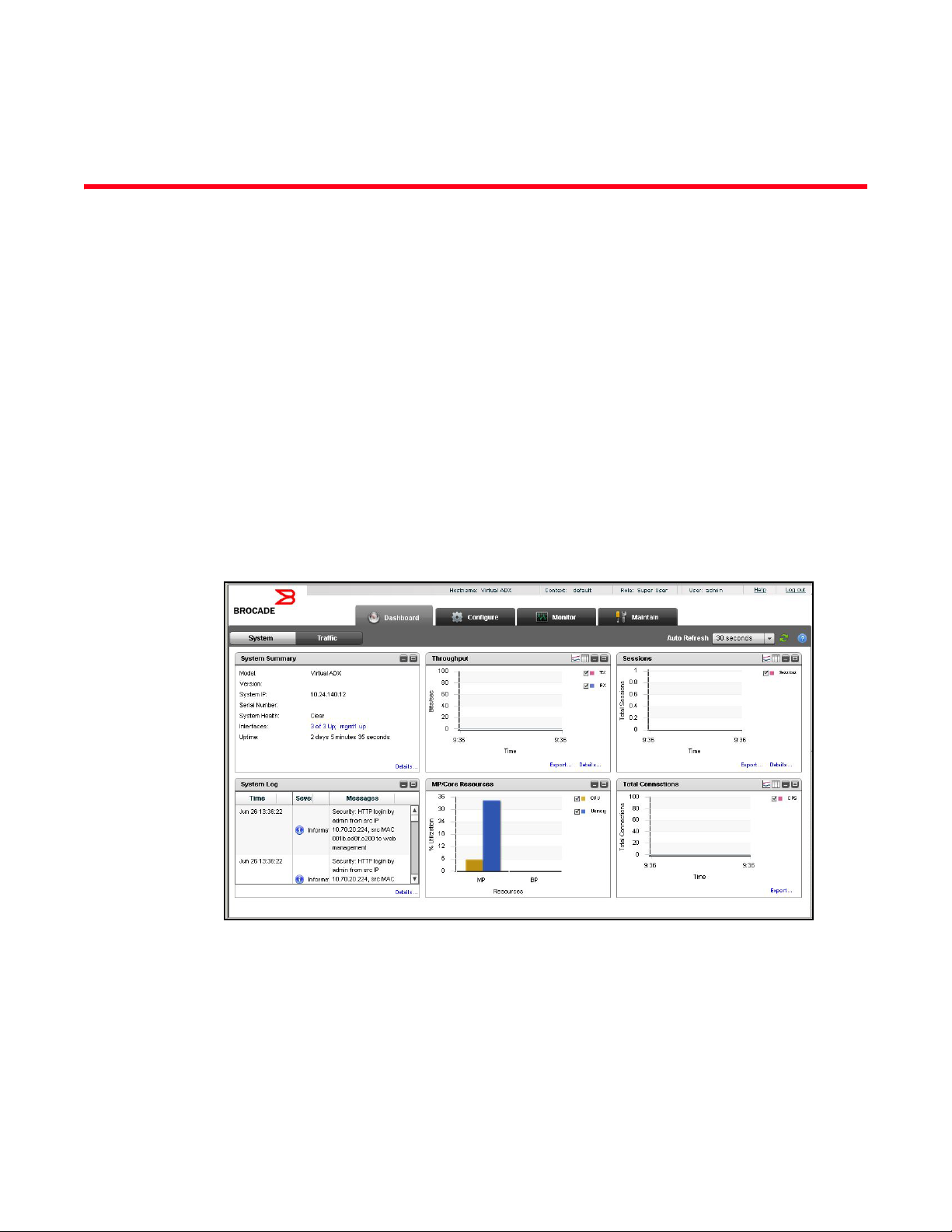
System view
The System dashboard displays various system information including general summary,
throughput, log messages, established connections, and sessions.
To vi ew the System dashboard, select the Dashboard tab in the task bar and click System on the
menu bar. The System dashboard page is displayed, as shown in Figure 6.
FIGURE 6 System dashboard
The System Dashboard contains six pods. See Table 2.
TABLE 2 System Dashboard pods
Pod Description
System Summary Displays system details including:
• Model
• Version
• System IP
• Serial Number
• System Health
• HA Mode
• Interfaces
• Uptime
Throughput Allows you to monitor the total number of packets received and
transmitted by the Brocade Virtual ADX.
Sessions Allows you to monitor the total number of sessions created with respect to
time.
System Log Allows you to monitor the system log messages and errors in the Brocade
Virtual ADX
MP/Core Resources Allows you to monitor the memory and CPU utilization in the Brocade
Virtual ADX
Total Connections Allows you to monitor the total number of connections established with the
Brocade Virtual ADX.
12 Brocade Virtual ADX Graphical User Interface Guide
53-1003242-01
Page 25

Traffic view
Traffic view
The Traf fic dashboard displays network traffic information including traffic distribution, sessions
and connections for service, and service response time.
To vi ew the Traffic dashboard, select the Dashboard tab in the task bar and click Tra ff ic on the
menu bar.
The Traf fic dashboard page is displayed, as shown in Figure 7.
3
FIGURE 7 Traffic dashboard
The Traf fic dashboard contains six pods. See Table 3.
TABLE 3 Traffic dashboard pods
Pod Description
Traffic Summary Allows you to monitor the status of the virtual servers, real servers, and
ports configured on the Brocade Virtual ADX in a tabular format. You can
also monitor the following:
• Total count of virtual servers, real servers, and ports.
• Maximum number virtual servers, real servers, and ports that can be
configured on the Brocade Virtual ADX.
• Number of virtual servers, real servers, and ports that are disabled.
Throughput by Service Allows you to monitor the transmission and reception of packets in bits per
seconds (BPS) over time based on Hypertext Transfer Protocol (HTTP),
Hypertext Transfer Protocol secure (HTTPS), Domain Name System (DNS).
Connections by Service Allows you to monitor the sessions over time based on HTTP, HTTPS, and
DNS.
Traffic Distribution - IPv4 vs IPv6 Allows you to monitor the client traffic based on IPv4 versus IPv6.
Brocade Virtual ADX Graphical User Interface Guide 13
53-1003242-01
Page 26

3
Traffic view
TABLE 3 Traffic dashboard pods (Continued)
Pod Description
HTTP Traffic - Content Switching Allows you to view the HTTP traffic request response.
Average Response Time by Service Allows you to monitor response over time based on HTTP, HTTPS, or DNS.
14 Brocade Virtual ADX Graphical User Interface Guide
53-1003242-01
Page 27

Chapter
Configuration Overview
In this chapter
•Navigating the configuration tab . . . . . . . . . . . . . . . . . . . . . . . . . . . . . . . . . . 15
•Saving the configuration . . . . . . . . . . . . . . . . . . . . . . . . . . . . . . . . . . . . . . . . . 16
Navigating the configuration tab
The Configure tab is the second tab in the Brocade Virtual ADX web interface.
FIGURE 8 Configure tab
You can use the Configure tab to configure the system, network, traffic, or security settings on an
Brocade Virtual ADX. When you click the Configure tab, the following menus are displayed in the
menu bar. See Table 4.
4
TABLE 4 Configure tab menu bar
Menu Description
System Allows you to configure the features specific to basic system settings and
limits, High Availability (HA), and user management.
Network Allows you to configure the features specific to interfaces, static routes,
and Virtual Local Area Networks (VLANs).
Traffic Allows you to configure the features specific to virtual server, real server,
health checks, content switching, and OpenScripts.
GSLB Allows you to configure the feature specific to the Global Server Load
Balancing (GSLB) site.
Security Allows you to configure the features specific to Secure Socket Layer (SSL)
and certificate management.
By default, the Brocade Virtual ADX web interface displays the System menu after you click the
Configure tab.
Click a menu that represents the primary task that you want to perform from the menu bar, the
corresponding entities specific to the menu are displayed in the sidebar. From the sidebar, select
an entity that represents a configuration feature. The corresponding Summary page with a list of
configured entities specific to the feature in tabular format is displayed in the main page. For
example, when you select the Real Servers entity from the sidebar, the main page displays a
summary page with the list of real servers configured in the Brocade Virtual ADX. The list displays
up to 30 configuration entries. You can navigate to view the next or previous set of configuration
Brocade Virtual ADX Graphical User Interface Guide 15
53-1003242-01
Page 28

Saving the configuration
4
information by clicking Next or Previous at the bottom of the Summary page. Click First or Last to go
to the most recent or least recent entries. Also, you can select the page number from the list, to go
to a specific page. The main page displays the buttons that are used to perform configuration
actions. See Tab le 5.
TABLE 5 Configuration actions
Button Description
New Allows you to create a new instance of the currently selected entity.
Edit Allows you to modify the attributes of the currently selected entity.
Delete Allows you to delete a configured entity from the Brocade Virtual ADX. All
nested configurations within the deleted configured entity are also
discarded.
Apply Applies changes to the running configuration.
Reset Reverts the configuration on the current page to the previous configured
values.
Common icons
The main page displays the common icons on the top right corner for all the configuration tasks.
See Tab le 6.
TABLE 6 Configuration icons
Icon Description
Filter Allows you to filter the data currently displayed in the Summary page. Click
Refresh Refreshes the current page based on the most recent changes made to
Save Saves the running configuration to the startup configuration.
Saving the configuration
When you change the current configuration or add any new configuration, the Brocade Virtual ADX
stores the configuration data in the running configuration. To permanently save the configuration to
the startup configuration of the Brocade Virtual ADX, click the Save button at the top right corner of
the main page.
the Filter icon and select the criteria from the Filter Criteria list to filter the
data.
the running configuration. Includes an option to set the interval at which
you want the page has to refreshed.
16 Brocade Virtual ADX Graphical User Interface Guide
53-1003242-01
Page 29

Chapter
System Settings
In this chapter
•General settings . . . . . . . . . . . . . . . . . . . . . . . . . . . . . . . . . . . . . . . . . . . . . . . 17
•High Availability . . . . . . . . . . . . . . . . . . . . . . . . . . . . . . . . . . . . . . . . . . . . . . . . 20
•Config Sync . . . . . . . . . . . . . . . . . . . . . . . . . . . . . . . . . . . . . . . . . . . . . . . . . . . 24
•Templates. . . . . . . . . . . . . . . . . . . . . . . . . . . . . . . . . . . . . . . . . . . . . . . . . . . . . 26
•User management . . . . . . . . . . . . . . . . . . . . . . . . . . . . . . . . . . . . . . . . . . . . . . 32
•Device management . . . . . . . . . . . . . . . . . . . . . . . . . . . . . . . . . . . . . . . . . . . . 39
General settings
After logging in to the web interface, configure the basic system information to identify your device
in the network and set the system limits to control the memory usage.
5
Configuring basic system settings
Configure the basic system settings including the host name. To configure the basic system
settings on the Brocade Virtual ADX, perform the following steps within the Configure tab.
1. Click System on the menu bar.
2. From the sidebar, click General.
Brocade Virtual ADX Graphical User Interface Guide 17
53-1003242-01
Page 30

General settings
NOTE
5
The System Configuration page is displayed. See Figure 9.
FIGURE 9 System Configuration page
3. Under System, provide the following information:
• Hostname: Enter a host name for the Brocade Virtual ADX; for example, ADXHost. When
you configure a host name, the name replaces the default system name. The name can
contain up to 32 alphanumeric characters.
• Serial Number: Displays the serial number of the Brocade Virtual ADX. The field is editable.
All the configuration changes performed in the web interface are stored in the running configuration.
Click the Save icon to save the running configuration to the startup configuration.
For more information on the basic system settings, refer to the Brocade Virtual ADX Switch and
Router Guide.
You can use the links under Quick Links to helpful Tasks, to navigate to real servers, virtual servers,
health checks, and content switching policy configurations.
18 Brocade Virtual ADX Graphical User Interface Guide
53-1003242-01
Page 31

General settings
NOTE
5
Changing the system limits
You can set the system memory consumption limits to control the Brocade Virtual ADX. To configure
the system limits on the Brocade Virtual ADX, perform the following steps within the Configure tab.
1. Click System on the menu bar.
2. From the sidebar, select General, and then select System Limits.The System Limits page is
displayed.
See Figure 10.
FIGURE 10 System Limits page
The default and range values for the resources displayed on this page are dependent on the active
license for your device. For more information, refer to the Brocade Virtual ADX Licensing Guide.
3. Provide the following information
• VLANs: Enter the maximum number of Virtual Local Area Networks (VLANs) you want to
assign to a group. The default value is 32. Enter a number from 32 to 256.
• L3 VLANs: Enter the maximum number of Layer 3 VLANs you want to configure on the
Brocade Virtual ADX. The default value is 16. Enter a number from 16 to 128.
• L4 Virtual Servers: Enter the maximum number of Layer 4 virtual servers you want to
configure on the Brocade Virtual ADX. The default value is 32. Enter a number from 32 to
64.
• L4 Real Severs: Enter the maximum number of Layer 4 real servers you want to configure
on the Brocade Virtual ADX. The default value is 256. Enter a number from 64 to 512.
• L4 Server Ports: Enter the number of Layer 4 server ports you want to configure on the
Brocade Virtual ADX. The default value is 2048. Enter a number from 256 to 4096.
• Sessions: Enter the maximum number of active sessions you want to allow on a device.
The default value is 512. Enter a number from 128 to 1024.
4. Click Apply to save your entries.
Brocade Virtual ADX Graphical User Interface Guide 19
53-1003242-01
Page 32

High Availability
NOTE
5
Click Reset to Defaults to change all the configured values to the default values. Click Reset to
revert the configuration to the previous configured values.
Any change to the system limits requires you to reboot the Brocade Virtual ADX for these changes to
take effect. It is recommended to save the running configuration to the startup configuration to
preserve the changes across reboot.
For more information on setting the system limits, refer the Brocade Virtual ADX Switch and Router
Guide.
Viewing and saving the configuration
When you edit a configuration, the changes are implemented in the running configuration. You can
view the running configuration and save a local copy of the running configuration.
To view the running configuration of the Brocade Virtual ADX, perform the following steps within the
Configure tab.
1. Click System on the menu bar.
2. From the sidebar, select General, and then select Running Configuration.
The Running Configuration page is displayed.See Figure 11.
FIGURE 11 Running Configuration page
3. Click the View Configuration button to review the configuration that is currently running on the
Brocade Virtual ADX.
Click the Download Configuration button to save a local copy of the running configuration to a
text file.
High Availability
High Availability (HA) is a system design and service implementation that prevents downtime and
ensures uninterrupted service.
HA overview
To configure the HA feature on the Brocade Virtual ADX, the setup requires two Brocade Virtual
ADXs, where one device must be active and the other device must be in the standby mode. The
active device accepts connections and manages servers, and the standby device monitors the
active device. If the active device fails to accept connections, the standby device takes over the
active device functions.
20 Brocade Virtual ADX Graphical User Interface Guide
53-1003242-01
Page 33

High Availability
NOTE
The HA for Server Load Balancing (SLB) is Hot-Standby HA. This mode requires a setup of two
Brocade Virtual ADXs, where one device is always active and the other device is always in the
standby mode. For more information on high availability, refer to the Brocade Virtual ADX Server
Load Balancing Guide.
5
Configuring the Brocade Virtual ADX in Hot-Standby HA
Hot-Standby HA allows you to configure two Brocade Virtual ADXs to serve as a redundant pair. One
device is always active while the other device is always standby. If the active device fails, the idle
standby device assumes the active functions and becomes the new active device.
Hot-Standby HA is the only HA service counting the number of available router and server ports for
failover behavior. the Brocade Virtual ADX with the highest number of active ports is declared as
the active device. A failover is triggered when device stops responding or during a system reload, in
addition to the port-count loss.
Hot-Standby HA is supported only in switch code.
To configure Hot-Standby HA on the Brocade Virtual ADX that runs switch code, perform the
following steps within the Configure Tab.
1. Click System on the menu bar.
2. From the sidebar, select High Availability.
The High Availability page is displayed. See Figure 12.
FIGURE 12 High Availability page
3. Select Setup Hot Standby.
The Hot Standby page is displayed. See Figure 13.
Brocade Virtual ADX Graphical User Interface Guide 21
53-1003242-01
Page 34

High Availability
5
FIGURE 13 Configuring hot standby
4. Under the Basic tab, provide the following information:
• Sync VLAN: Select a port-specific VLAN from the list.
• Sync Port: Select the hot standby port from the list. Placing the hot standby port in its own
VLAN prevents unnecessary traffic from going over the directly connected backup link.
• Shared MAC Address: Specify the MAC address of one of the Brocade Virtual ADXs. You
must use a MAC address of the Brocade Virtual ADXs, not the MAC address of the backup
ports.
• Shared MAC: Select the Enabled check box to enable the shared MAC address. When you
enable shared MAC addresses, make sure that the Brocade Virtual ADX is in promiscuous
mode.
• Router Ports: Select the number of router ports from the Available list and click Add to
specify the ports for the active device. Click Remove to remove an added router port. Both
the Brocade Virtual ADXs in the hot standby must use the same router-ports numbers.
• Health Check: Select the configured health check for the ports.
5. To configure the advanced parameters for the hot standby configuration, click the Advance tab.
The Advance tab is displayed. See Figure 14.
22 Brocade Virtual ADX Graphical User Interface Guide
53-1003242-01
Page 35

High Availability
FIGURE 14 Hot standby advanced configuration
6. Under the Advanced tab, provide the following information:
• Backup Remain Standby: Select the Enable check box to force the Brocade Virtual ADX to
remain in the standby state, regardless of any changes in the system parameters (such as
no heart beat, fewer router ports, and other changes). The Brocade Virtual ADX transitions
to the standby state and remains as the standby until this setting is disabled.
• Backup Sync Disable: Select the Enable check box to enable the synchronization of an SLB
configuration from the active Brocade Virtual ADX to the standby Brocade Virtual ADX. This
setting is disabled by default.
• Backup Preference: Enter the time interval during which the standby device waits for the
configured time before taking the active role. The range is from 5 through 30 minutes. The
default value is 5 minutes.
• Backup Timer: Enter the time for the backup device to wait for a Hello message or
synchronization data from the active device before assuming the active device is no longer
available. The range is from 5 through 100. The default value is 10.
• Backup Interval: The backup interval represents the timer count in units of
100 millisecond.
• Backup Group: Enter the backup group ID to configure the hot standby pairs within a single
Layer 2 broadcast domain for exchanging the backup information.
• Failover Delay Time: Enter the time in seconds for which the Brocade Virtual ADX to wait
before beginning the failover check in seconds. The range is from 0 through 1200
seconds. The default value is 0 seconds.
• Tra c k Acti ve VIP Count: Select the Enable check box to configure the failover based on the
router ports and the active VIP counts.
• Track Virtual Port Count: Select the Enable check box to allow the Brocade Virtual ADX to
track the failure of the virtual port.
5
7. Cl i c k Apply to save your entries.
Click Reset to revert the configuration to the previous configured values.
For more information on hotstandby configuration, refer to the Brocade Virtual ADX Server Load
Balancing Guide.
Brocade Virtual ADX Graphical User Interface Guide 23
53-1003242-01
Page 36

Config Sync
5
Config Sync
The Config Sync controls allow you to configure the Brocade Virtual ADX for automated
synchronization.
Config Sync Summary tab
To configure the Config Sync settings on the Brocade Virtual ADX, perform the following steps
within the Configure tab.
1. Select the Configure tab.
2. Click System on the menu bar.
3. From the sidebar, select Config Sync.
By default, only the Summary page is displayed when you first select Config Sync. See
Figure 15.
FIGURE 15 Config Sync Summary page
The Config Sync Summary tab has the following controls. See Table 7.
TABLE 7 Config Sync summary tab controls
Control Description
Sync State Read-only field with a colored indicator for each state. Options are:
• Red indicator: Not available or not in sync
• Yellow indicator: Sync in progress or not retrieved yet
• Green indicator: In sync
Last Sync Date and time of last synchronization.
Last Config Change Date and time of last configuration change.
Use the Config Sync Summary tab to:
• Navigate to the Sync Settings tab. Click the Sync Settings... button. See “Config Sync Settings
tab”.
24 Brocade Virtual ADX Graphical User Interface Guide
53-1003242-01
Page 37

Config Sync
Config Sync Settings tab
To configure the Config Sync synchronization controls on the Brocade Virtual ADX, perform the
following steps within the Configure tab.
1. Select the Configure tab.
2. Click System on the menu bar.
3. From the sidebar, select Config Sync.
4. Click the Sync Settings… button.
The Sync Settings tab is displayed. See Figure 16.
FIGURE 16 Sync Settings page
5
The Config Sync Settings tab has the following controls. See Table 8 .
TABLE 8 Config Sync Settings tab controls
Column Content
Sync State Read-only field. Options are:
• Not available or not in sync (Red indicator)
• Sync in progress or sync not retrieved yet (yellow indicator)
• In sync (green indicator)
Sync Mode Device role. Options are Sender, Receiver, or None (not enabled).
Sync Port Port used for synchronization.
Sync VLAN VLAN ID for synchronization.
Sync MAC Address MAC address used for synchronization. This value is required for devices configured as
Sender, and optional for devices configured as Receiver.
Click Apply at the bottom right corner to apply any change you have made, or click Reset to discard
all changes.
Brocade Virtual ADX Graphical User Interface Guide 25
53-1003242-01
Page 38

Templates
NOTE
5
Templates
The Templates controls allow you to upload and run XML-based Config Templates for the
configuration and management of the Brocade Virtual ADX. Though you can create templates,
Brocade provides pre-defined templates. These templates exist in the Brocade Virtual ADX and can
be used though the Web GUI.
You can use the Config Templates on the CLI or in user-written SOAP clients.
For more information on the Config Template XML schema and managing the Config Templates
through the CLI, refer to the following appendices:
• Appendix B, “Config Template XML Schema”
• Appendix C, “Managing Config Templates through the CLI”
For information on the Config Template XML System APIs, refer to the Brocade Virtual ADX XML API
Programmer’s Guide.
Templates Summary tab
To view the list of predefined and user-defined Config Templates on the Brocade Virtual ADX,
perform the following steps within the Configure tab.
1. Select the Configure tab.
2. Click System on the menu bar.
26 Brocade Virtual ADX Graphical User Interface Guide
53-1003242-01
Page 39

3. From the sidebar, select Templ ates.
The Temp lates page is displayed. See Figure 17.
FIGURE 17 Tem plat es page
Templates
5
The page displays the Templa tes tab with the following information:
• File Name: The template filename.
• Name: A descriptive name for the template.
• Description: A description of the template.
• Version: The version of the template.
• Storage Area: The storage area where the template file resides. Possible values are as
follows:
• Pre-defined, templates provided as part of the Brocade Virtual ADX build.
• User-defined, templates created by a user.
• Ready-to-use, templates that do no require any user inputs and are ready to be
executed. Typically, these templates are copies of template files from one of the other
storage areas. However, the user inputs are already filled in the template making it
ready for use.
From the Templ ates page, you can perform the following operations:
• Deleting a User-defined or Ready-to-Use template from the list by selecting it and clicking
Delete. You cannot delete a Pre-defined template.
• “Uploading a local Config Template file”
• “Copying a Config Template through TFTP”
• “Executing a Config Template”
• “Viewing the Raw XML and Tree Structure of a template”
Brocade Virtual ADX Graphical User Interface Guide 27
53-1003242-01
Page 40

5
NOTE
Templates
Uploading a local Config Template file
To upload a local template file, perform the following steps within the Templates tab.
The maximum file size that can be loaded from the local system is 750K.
1. Select the Configure tab.
2. Click System on the menu bar.
3. From the sidebar, select Templ ates.
4. Click the Upload button.
The Upload page is displayed at the bottom of the Templates tab. See Figure 18.
FIGURE 18 Upload page on the Templates tab
5. Provide the following information:
• Save As File Name: Optionally, enter the name of the template if you want to upload a
template on the device with a different name. If you leave this field blank, the template will
be uploaded with the same name.
• Local Template File to Upload: Click Browse and select the template from your local
directory to upload to the device.
6. Click Upload Template File.
Click Clear to clear all the entries in the fields.
Copying a Config Template through TFTP
To copy a template file through TFTP by specifying its address and filename, perform the following
steps within the Templ ate s tab.
1. Select the Configure tab.
2. Click System on the menu bar.
28 Brocade Virtual ADX Graphical User Interface Guide
53-1003242-01
Page 41

Templates
3. From the sidebar, select Templ ates.
4. Click the TFTP Copy button.
The TFTP Copy page is displayed at the bottom of the Templates tab. See Figure 19.
FIGURE 19 TFTP Copy on the Temp lates tab
5
5. Provide the following information:
• TFTP IP Address: Enter the IP address of the TFTP server.
• TFTP File To Copy: Enter the name of the template to copy from the TFTP server.
• Save Template As File Name: Optionally, enter the name of the template if you want to
upload the template on the device with a different name. If you leave this field blank, the
template will be uploaded with the same name. Do not enter include any spaces when you
enter the name.
6. Click Copy Template File.
The Brocade Virtual ADX starts the TFTP file transfer in the background, polls and displays the
progress of the transfer, and determines when the transfer has succeeded or failed. When the
transfer succeeds, the Brocade Virtual ADX adds the template to the list.
To clear all the entries in the fields, click Clear.
Executing a Config Template
To execute a Config Template, perform the following steps within the Templa tes tab.
1. Select the Configure tab.
2. Click System on the menu bar.
3. From the sidebar, select Templ ates.
4. Select a Config Template from the list of filenames.
Brocade Virtual ADX Graphical User Interface Guide 29
53-1003242-01
Page 42

5
Templates
5. Click Open.
The Template - filename page is displayed.
• If the template does not require user input before execution, the following message
appears on the page:
This template has no variables.
• If the template requires user entries, enter the information in the variables fields, similar to
Figure 20. Depending on the template you have selected, the data fields may be different
from this example; every template may require different user inputs.
FIGURE 20 Templates - User Input page
Some fields may already contain default values that you can change individually. When
you start to enter information in the variable fields, the Reset button is enabled to clear all
entries in the fields.
6. Select Save changes performs a write memory operation to save the running configuration
after and only if the template has completed a successful execution.
7. Se l e c t Reload after execution if you want to reload the Brocade Virtual ADX after executing the
template. The reboot occurs only when the execution is successful.
8. Click Execute.
The Brocade Virtual ADX checks the template and validates it before its execution.
• If the template is validated and the execution is successful, the Status displays Completed
and the Overall Result displays OK. The results of the template appear in the Web GUI.
• If a validation or execution failure occurs, the Status displays Failed and the Overall Result
displays Error. The error messages displays the following information:
• Typ e, either Validation or Execution Failure.
• Message, a brief error message of the failure.
• Detail, detailed information of the failure. Place your cursor over the information to
display the full details of the information.
Also, Template execution status: Failed appears.
30 Brocade Virtual ADX Graphical User Interface Guide
53-1003242-01
Page 43

Templates
Viewing the Raw XML and Tree Structure of a template
From the View Template tab, you can view the raw XML and the tree structure of the Config
Template.
1. Select the template from the Temp late s tab
2. Click View to view the View Raw XML and Browse Tree Structure tabs. See Figure 21.
FIGURE 21 View Raw XML
5
• The View Raw XML tab contains the XML for the template. Within the text area, you can
select sections of the XML and copy it into the clipboard and paste it into an editor for use
with another template.
• Select the Browse Tree Structure tab to view more detail of the contents of the raw XML
and how it has been set up. See Figure 22.
FIGURE 22 Browse Tree Structure
Brocade Virtual ADX Graphical User Interface Guide 31
53-1003242-01
Page 44

User management
5
User management
User management allows restricting or authorizing system access for the users based on their
context. You can view the user name, role and context associated with the logged in user in the
login bar. See Figure 23.
FIGURE 23 Viewing user management information
Basic user management
You can configure three types of users in the Brocade Virtual ADX:
• Super user — A super user has admin access privileges and can view, edit and delete all
configurations. Only a super user can create new users. You must have a super-user account to
make further administrative changes.
• Read-only user — A read-only user has only view permissions and all the configuration buttons
including new, edit and delete are disabled.
• Role-based user — A role-based user has permissions to perform certain operations based on
their roles.
Managing role-based users
As a role-based user, a user can be assigned with three different roles:
• Manager — A user defined under Manager role has view, edit, and delete permissions.
• Operator — A user defined under Operator role has permissions to enable or disable elements,
such as servers or interfaces, and has read-only permissions for all other operations.
• Viewer — A user defined under Viewer role has read-only permissions.
There are two types of configurations in the Brocade Virtual ADX.
• Global configuration — It refers to Layer 2, Layer 3, and other miscellaneous configurations on
the Brocade Virtual ADX.
• Context-related configurations — It includes real server, virtual server, content switching,
OpenScript, and session. In general, all the traffic-related configurations are related to context.
In the role-based configuration, you can assign the user different roles for global configurations and
context-related configurations. For example, you can assign manager role for global configuration
and viewer role for context-related configurations.
32 Brocade Virtual ADX Graphical User Interface Guide
53-1003242-01
Page 45

User management
To create a user on the Brocade Virtual ADX, perform the following steps with the Configure tab.
1. Click System on the menu bar.
2. From the sidebar, select User Management.
The Users page is displayed. See Figure 24.
FIGURE 24 Users page
5
The Users page displays the list of configured user accounts. Each entry in the list includes the
user name, user type, associated role template and context.
Brocade Virtual ADX Graphical User Interface Guide 33
53-1003242-01
Page 46

User management
NOTE
5
3. Click New at the bottom of the Summary page.
The User - new page tab is displayed. See Figure 25.
FIGURE 25 User - new page
4. Under the User Information tab, provide the following information:
• User Name: Enter a unique name for the local user account.
• User Type: Click Super User, Role Based User, or Read Only User based on the privilege
level.
The options in the Role Based Settings tab are enabled only when you click Role Based
User type. For more information on the configuration of role-based user, refer to “Assigning
a user role” on page 35.
• Change Password: Select the Yes check box to change the password.
• Password: Enter the password with a minimum of eight characters. The password is always
masked to ensure security.
• Confirm Password: Enter the password again for confirmation.
• Password Expiry Time (days): Enter the number of days for the password validity. The range
is from 1 through 365 days. The default is 90 days.
5. Click Apply to save your entries.
Click Reset to revert the configuration to the previous configured values.
To modify the configured user information, in the Summary table, select an entry and click Edit or
double-click the entry. You can also delete a user by clicking Delete.
34 Brocade Virtual ADX Graphical User Interface Guide
53-1003242-01
Page 47

User management
NOTE
NOTE
You cannot delete the user currently logged in to the Brocade Virtual ADX.
Assigning a user role
When the user type is selected as role-based, the fields under the Role Based Settings tab are
enabled.
1. Click the Role Based Settings button.
The Role Based Settings tab is displayed. See Figure 26.
FIGURE 26 Assigning user role
5
2. Provide the following information:
• Global (non-Context) Config: Click None, Viewer, or Manager to assign a role for the global
configuration pages.
• Default Context: Select the context that has to be associated with the user by default.
• Role Template: Select the role template that is to be associated with the user.
• Under Context/Role Mappings, enter the following information:
• New Context Name: Select a context name that you want to assign to the user.
• Role: Select a role that you want to assign to the user.
• Click Add.
The context names along with their respective roles are displayed in the table.
To delete a context-role mapping entry from the table, select an entry from the table and
click Delete. Click Delete All to delete all the entries.
Brocade Virtual ADX Graphical User Interface Guide 35
53-1003242-01
Page 48

User management
5
3. Click Apply to save your entries.
Click Reset to revert the configuration to the previous configured values.
For more information on role based users, refer to the Brocade Virtual ADX Administration Guide.
Creating contexts
After login, the user is automatically associated with the configured context or default context. To
edit the context-related configurations, the user must be associated with that context. Within a
context, a user can be a manager, operator, or viewer of the context-related configurations. A user
can navigate to different contexts by selecting the context name in the login bar.
To create a context on the Brocade Virtual ADX, perform the following steps within the Configure
tab.
1. Click System on the menu bar.
2. From the sidebar, select User Management.
3. Select Contexts.
The Contexts page is displayed. See Figure 27.
FIGURE 27 Contexts page
4. Enter the context name, for example, Finance in the Context Name field.
36 Brocade Virtual ADX Graphical User Interface Guide
53-1003242-01
Page 49

User management
NOTE
5. Click Add.
The context name is displayed in the Current Contexts table.
To delete a context configuration, select an entry from the Current Contexts table and click
Delete.
A context cannot be deleted if it is referenced.
For more information on creating the contexts, refer to the Brocade Virtual ADX Administration
Guide.
5
Creating role templates
For simplicity of the configuration, the super user can create a role template with specific roles
assigned for global and context-related configurations. You can assign the role template to the user
to grant the privileges in the template.
To create a role template on the Brocade Virtual ADX, perform the following steps within the
Configure tab.
1. Click System on the menu bar.
2. From the sidebar, select User Management.
3. Select Role Templates.
The Role Templates page is displayed. See Figure 28.
FIGURE 28 Role templates summary page
The Role Templates page displays the list of configurated role templates, 30 entries at a time.
Each entry includes role template name, role, default context, and its active status.
Brocade Virtual ADX Graphical User Interface Guide 37
53-1003242-01
Page 50

User management
NOTE
5
4. Click New at the bottom of the Role Templates page.
The Role Template - new page tab is displayed. See Figure 29.
FIGURE 29 Role template - new page
5. Provide the following information:
• Role Template Name: Enter the name of the role template.
• Default Context: Select the context you want to associate with the user by default.
• Global (non-Context) Config: Click None, Viewer, or Manager to assign a role for the global
configurations.
6. In the Context/Role Mappings, provide the following information:
• New Context Name: Select a context you want to associate with the role template.
• Role: Select a role you want to associate with the role template.
• Click Add.
The context names with their respective roles are displayed in the table.
To delete a context-role mapping from the table, select an entry from the table and click Delete.
Click Delete All to delete all the entries.
7. Cl i c k Apply to save your entries.
Click Reset to revert the configuration to the previous configured values.
For more information on role templates, refer to the Brocade Virtual ADX Administration Guide.
38 Brocade Virtual ADX Graphical User Interface Guide
53-1003242-01
Page 51

Device management
Device management controls allow you to configure how the Brocade Virtual ADX is accessed.
Configuration controls are provided for the following protocols:
• SNMP
• SSH
• Telnet
• TFTP on VLAN
To display the Device Management Summary page, perform the following steps within the
Configure tab.
1. Click System on the menu bar.
2. From the sidebar, select Device Management.
Use the Device Management Configuration Page to navigate to the pages that allow you to manage
SNMP, SSH, Telnet, and TFTP.
SNMP controls
Device management
5
To configure SNMP settings on the Brocade Virtual ADX, perform the following steps within the
Configure tab.
1. Click System on the menu bar.
2. From the sidebar, select Device Management.
3. Click SNMP in the sidebar sub-menu to display the SNMP controls.
By default, only the Settings tab is displayed when you first open this control set; the other
seven tabs for the SNMP controls are displayed by clicking their respective buttons at the
bottom of the page. Click on the links below to jump to a description of the features of that tab.
• “SNMP Settings tab”
• “Community Strings tab”
• “Clients tab”
• “V3 Users tab”
• “Traps tab”
• “Trap Receivers tab”
• “Views tab”
• “Groups tab”
4. Make your desired changes.
5. Click Apply at the bottom right corner of the window to apply any change you have made, or
click Reset to discard all changes.
Brocade Virtual ADX Graphical User Interface Guide 39
53-1003242-01
Page 52

Device management
5
SNMP Settings tab
To vi ew the SNMP Settings page, perform the following actions in the Configure tab:
1. Click System on the menu bar.
2. From the sidebar, select Device Management.
3. Click SNMP in the sidebar sub-menu to display the SNMP controls.
The SNMP Settings tab is displayed. See Figure 30.
FIGURE 30 SNMP Settings page
The SNMP Settings tab has the following controls. See Tabl e 9.
TABLE 9 SNMP Settings tab controls
Field Content
Contact The email address to be used by this server for alerts and messages.
Location The location name for this server. This will be printed in any traps that may occur.
Configure RADIUS
enabled
Configure TACACS
enabled
Password check If marked, requires password on login.
V3 Engine ID The V3 Engine ID for this server. This is a read-only field.
Trap Source The source interface to be used for traps.
VLAN ID The VLAN ID of this server. (Optional)
Allowed Ports Marking the checkbox for a port enables it; unmarking the checkbox disables it.
If marked, enables RADIUS configuration. See “RADIUS controls”.
If marked, enables TACACS configuration. See “TACACS controls”.
40 Brocade Virtual ADX Graphical User Interface Guide
53-1003242-01
Page 53

Device management
5
Community Strings tab
The Community Strings tab displays an editable list of the server’s Community Strings. To view the
SNMP Settings page, perform the following actions in the Configure tab:
1. Click System on the menu bar.
2. From the sidebar, select Device Management.
3. Click SNMP in the sidebar sub-menu to display the SNMP Settings tab.
4. Click the Community Strings button at the bottom of the window.
The Community Strings tab is displayed. See Figure 31.
FIGURE 31 Community Strings page
The Community Strings tab displays an editable list of the server’s Community Strings, with the
following controls to a edit a selected community string or add a new community string. See
Tab le 10.
TABLE 10 Community Strings tab controls
Controls Description
Community String The community name. A Community String acts like a password and permits access to the
SNMP protocol. Enter the community string name. The name can be up to 32 alphanumeric
characters.
Encryption Select the Enabled check box to enable encryption on the community string. Encryption is
enabled by default. Users with read-only access or who do not have access to management
functions in the CLI cannot display the strings. For users with read-write access, the strings
are encrypted in the CLI but are shown in the clear in the Web Management Interface.
Brocade Virtual ADX Graphical User Interface Guide 41
53-1003242-01
Page 54

Device management
5
TABLE 10 Community Strings tab controls (Continued)
Controls Description
Read Only Select the check box to assign read-only (R/O) access to the Community String, meaning
that authorized management stations are able to only retrieve MIB objects. If the check box
is not selected, the community string has read-write access. If you do not select the check
box, the Community String is read-write (R/W), meaning that authorized management
stations are able to both retrieve and modify MIB objects.
View Name Name of a defined view. The view defines the objects available to the community. Enter the
name to identify the view. The name can be any alphanumeric name with no spaces.
Perform the following functions in the Community Strings tab:
• To add a community string, enter the information in controls described in Tab le 10 . To save the
information and display the information in the table, Click Add.
• To edit an existing community string in the table, select the community string to populate the
associated editing fields with the contents of its row. To save the changes to the edited
community string, click Update.
• Select one or more rows to enable the Delete button to delete Community Strings from the
table.
• Click Clear to deselect all rows and empty the edit fields in order to create a new Community
String.
Clients tab
The Clients tab displays an editable list of client IP addresses allowed access to the server. To view
the Clients page, perform the following actions in the Configure tab:
1. Click System on the menu bar.
2. From the sidebar, select Device Management.
3. Click SNMP in the sidebar sub-menu to display the SNMP Settings tab.
42 Brocade Virtual ADX Graphical User Interface Guide
53-1003242-01
Page 55

4. Click the Clients button at the bottom of the window.
The Clients tab is displayed. See Figure 32.
FIGURE 32 Clients page
Device management
5
The SNMP Clients tab has the following controls. See Table 11.
TABLE 11 SNMP Clients tab controls
Column Content
Allowed Client IP Allowed client IP address (IPv4). Once created, it cannot be altered; it can only be deleted.
Add New Entry Field for adding/editing IP address entries.
Perform the following functions in the Clients tab:
• Select a single row in the table to populate the associated editing fields with the contents of
that row.
• Select one or more rows to enable the Delete button to delete Clients from the table.
• Click Clear to deselect all rows and empty the edit fields in order to create a new Client.
V3 Users tab
The V3 Users tab displays an editable table of V3 users allowed access to the server.
To vi ew the V3 Users page, perform the following actions in the Configure tab:
1. Click System on the menu bar.
2. From the sidebar, select Device Management.
3. Click SNMP in the sidebar sub-menu to display the SNMP Settings tab.
Brocade Virtual ADX Graphical User Interface Guide 43
53-1003242-01
Page 56

Device management
5
4. Click the V3 Users button at the bottom of the window.
The V3 Users tab is displayed. See Figure 33.
FIGURE 33 V3 Users tab
The SNMP V3 User tab has the following controls. See Tab le 1 2.
TABLE 12 SNMP V3 User tab
Column Content
User Name Displayed user name. Once created, it cannot be altered; it can only be deleted.
Group Group that this user is a member of.
Perform the following functions in the V3 Users tab:
• Select a single row in the table to populate the associated editing fields with the contents of
that row.
• Select one or more rows to enable the Delete button to delete V3 Users from the table.
• Click Clear to deselect all rows and empty the edit fields in order to create a new user.
In addition to the information in the table, this tab lets you set the values in the fields described in
Tab le 13 .
TABLE 13 SNMP V3 User tab fields
Column Content
Authentication Type How the user is authenticated. Options are MD5 and SHA. If the Encryption check
box is marked the authentication will be encrypted.
Authentication Password User authentication password. MD5 requires 8-16 characters, SHA requires 8-20,
and if encrypted, the requirement is 32 Hexadecimal characters.
Privacy Type Privacy options. Options are DES, 128-bit AES encryption for SNMP security
encryption, and SHA - 40 Hexadecimal characters when encrypted.
Privacy Password Password for the privacy option. Privacy password requires 12- 16 characters. An
AES password requires 12- 16 characters. A DES passwords requires 8- 16
characters. If you use a localized key, you can specify a maximum of 130
characters.
44 Brocade Virtual ADX Graphical User Interface Guide
53-1003242-01
Page 57

Device management
Traps tab
The Trap s tab displays a selectable list of Traps on the server.
To vi ew the Traps page, perform the following actions in the Configure tab:
1. Click System on the menu bar.
2. From the sidebar, select Device Management.
3. Click SNMP in the sidebar sub-menu to display the SNMP Settings tab.
4. Click the Traps button at the bottom of the window.
The Trap s tab is displayed. See Figure 34.
FIGURE 34 Traps page
5
The SNMP Trap tab has the following controls:
• Hardware Related
• Cold Start
• Link Up
• Link Down
• Layer 4 related
• HTTP Match List
• Maximum Session Limit
• Port Up
• Port Down
• Server Up
• Server Down
• Server Maximum Connections
• Switch Active
Brocade Virtual ADX Graphical User Interface Guide 45
53-1003242-01
Page 58

Device management
5
• Switch Standby
• TCP SYN Limit
• Other Traps
• Authentication
• Locked Address Violation
• STP New Root
• STP Topology Change
• OSPF
Use the Tra ps tab to perform the following functions:
• Set or disable an individual trap by marking or unmarking the check box for that trap.
• Click Expand All to see all the traps.
• Click Collapse All to collapse the tree so that only the top-level headers are displayed.
• Click Select All to activate all the traps.
• Click Unselect All to disable all traps.
Trap Receivers tab
The Trap Recei ver s tab displays an editable list of Trap Receivers on the server.
To vi ew the Trap Re ceive r s page, perform the following actions in the Configure tab:
1. Click System on the menu bar.
2. From the sidebar, select Device Management.
3. Click SNMP in the sidebar sub-menu to display the SNMP Settings tab.
46 Brocade Virtual ADX Graphical User Interface Guide
53-1003242-01
Page 59

4. Click the Trap Rec e iver s button at the bottom of the window.
The Trap Recei vers page is displayed. See Figure 35.
FIGURE 35 Trap Receivers page
Device management
5
The SNMP Trap Receiver tab has the following controls. See Tabl e 14.
TABLE 14 SNMP Trap Receiver tab controls
Column Content
Host Address Host Address being monitored. Once created, it cannot be altered; it can only be deleted.
Version The version of the received trap. Options are V1, V2C, or V3.
Port The port number for this trap. (range: 1–65535, default 162).
Note: If you choose a value other than 162, make sure the device sending the trap is also
sending to the specified port.
Use the Tra p Rece ivers table to perform the following functions:
• Select a single row in the table to populate the associated editing fields with the contents of
that row.
• Select one or more rows to enable the Delete button and delete trap receivers from the table.
• Click Clear to deselect all rows and empty the edit fields, making it easier to create a new trap
receiver.
In addition to the information in the table, this tab lets you set the following values:
• Community String: Community String to be used by this Trap Receiver.
• V3 Security Level: Security level to be used if V3 is selected as version. This is only active if V3
is selected as version. Options are:
• Authentication and Privacy
• Authentication
• None
• V3 User Name: User name to be used if V3 is selected as version. This is only active if V3 is
selected as version.
Brocade Virtual ADX Graphical User Interface Guide 47
53-1003242-01
Page 60

Device management
5
Views tab
To vi ew the Views page, perform the following actions in the Configure tab:
1. Click System on the menu bar.
2. From the sidebar, select Device Management.
3. Click SNMP in the sidebar sub-menu to display the SNMP Settings tab.
4. Click the Views button at the bottom of the window.
The Views page is displayed. See Figure 36.
FIGURE 36 Views page
The SNMP Views tab has the following controls. See Ta ble 1 5.
TABLE 15 SNMP Views tab controls
Column Content
View Name Displayed view name. Once created, it cannot be altered; it can only be deleted.
MIB Subtree MIB Subtree that this view displays.
View Type The view type for this view. Options are Included or Excluded.
Perform the following functions in the Views tab:
• Select a single row in the table to populate the associated editing fields with the contents of
that row.
• Select one or more rows to enable the Delete button and delete views from the table.
• Click Clear to deselect all rows and empty the edit fields, making it easier to create a new view.
48 Brocade Virtual ADX Graphical User Interface Guide
53-1003242-01
Page 61

Device management
Groups tab
To vi ew the Groups page, perform the following actions in the Configure tab:
1. Click System on the menu bar.
2. From the sidebar, select Device Management.
3. Click SNMP in the sidebar sub-menu to display the SNMP Settings tab.
4. Click the Groups button at the bottom of the window.
The Groups page is displayed. See Figure 37.
FIGURE 37 Groups page
5
The SNMP Groups tab has the following controls. See Table 16.
TABLE 16 SNMP Groups tab controls
Column Content
Name Displayed group name. Once created, it cannot be altered; it can only be deleted.
Security Model Security model used by this group. Options are V1, V2C, or V3.
V3 Security Level When you select v3, the security level determines whether authentication is required for
accessing the supported views.
• Authentication and Privacy: An authentication password is required from the users
• Authentication: Only authenticated packets are allowed to access the view specified
for the user group.
• None: No authentication is required to access the specified view.
Read Views Allow users who belong to this group to have read access to the MIB. (Optional)
Write Views Allow users who belong to this group to have write access to the MIB. (Optional)
Notify Views Allow trap notifications to be encrypted and sent to target hosts. (Optional)
Perform the following functions in the Groups tab:
• Select a single row in the table to populate the associated editing fields with the contents of
that row.
• Select one or more rows to enable the Delete button and delete groups from the table.
Brocade Virtual ADX Graphical User Interface Guide 49
53-1003242-01
Page 62

Device management
5
• Click Clear to deselect all rows and empty the edit fields, making it easier to create a new
group.
SSH controls
To configure SSH settings on the Brocade Virtual ADX, perform the following steps within the
Configure tab.
1. Select the Configure tab.
2. Click System on the menu bar.
3. From the sidebar, select Device Management.
4. Click SSH in the sidebar sub-menu to display the SSH controls.
The SSH Settings tab is displayed. See Figure 38.
FIGURE 38 SSH Settings tab
5. Click Apply at the bottom right corner to apply any change you have made.
Click Reset to discard all changes.
The SSH panel has the following controls. See Table 17.
TABLE 17 SSH panel controls
Control Description
SSH Enabled If marked, enables SSH configuration. If blank, all other controls are dimmed.
SCP If marked, enables the Secure Copy protocol.
Public Key
Authentication
Use Password
Authentication
Allow Empty Password If marked, allows the password field to be blank.
Authentication Retries Number of failed authentication attempts allowed before the account is locked.
50 Brocade Virtual ADX Graphical User Interface Guide
If marked, uses PKI-based authentication.
If marked, requires user authentication (ID plus password).
(range: 1–5, default is 3)
53-1003242-01
Page 63

Device management
TABLE 17 SSH panel controls (Continued)
Control Description
Login Timeout Length of time allowed to complete login. (range: 1–120 seconds, default is
120 seconds)
Idle Timeout Length of time account is allowed to have no activity. Enter a number from 0 to 240.
The default is 0. The value of 0 is no time out.
Key Size Size of account encryption key. (range: 512–1024 bits, default is 768 bits)
Port Number ID of port to be used by this account.(range: 1–65535, default is 22)
Interface Interface to be used by this account. (Optional)
ACL ID (IPv4) IPv4 ACL ID of this account. Options are None and values from 0–99. (Optional)
ACL ID (IPv6) IPv6 ACL ID of this account. Options are None and values from 0–99. (Optional)
Telnet settings
To configure Telnet settings on the Brocade Virtual ADX, perform the following steps within the
Configure tab.
1. Click System on the menu bar.
5
2. From the sidebar, select Device Management.
3. Click Tel net in the sidebar sub-menu to display the Telnet controls.
The Telnet Settings tab is displayed. See Figure 39.
FIGURE 39 Telnet Settings tab
Brocade Virtual ADX Graphical User Interface Guide 51
53-1003242-01
Page 64

Device management
5
The Telnet Settings tab has the following controls. See Table 18.
TABLE 18 Telnet Settings tab controls
Control Description
Telnet Select the Enable check box to enable Telnet access to the server. If you do not select
this check box, all other controls are dimmed and disabled.
Authentication Select the Enable check box to enable authentication on Telnet access to the server.
Password The password for Telnet access. Enter an password from 1 to 48 characters.
Encryption Select the Enable check box to encrypt the Telnet password.
Source Interface Choose an interface to be used for connecting to the server using Telnet.
Login Retries Number of failed authentication attempts allowed before the account is locked. Enter a
number from 0 to 5. The default is 4.
Login Timeout Length of time in minutes allowed to complete login. Enter a number from 1 to 10. The
default is 2 minutes.
Idle Timeout Length of time in minutes that an account is allowed to have no activity. Enter a
number from 0 to 240. The default is 0. The value of 0 is no time out.
VLAN ID (Optional) The VLAN ID of this server. Choose None or a value from 0 to 4095.
ACL ID (IPv4) IPv4 ACL ID of this account. Options are None and values from 0–99. (Optional)
ACL ID (IPv6) IPv6 ACL ID of this account. Options are None and values from 0–99. (Optional)
Use the Teln et Sett ings tab to perform the following functions after populating the necessary fields:
• Click Apply at the bottom right corner to apply any change you have made.
• Click Reset to discard all changes.
• Click the Telnet Allowed Clients button to display the Telnet Allowed Clients tab. See Telne t
Allowed Clients.
Telnet Allowed Clients
To vi ew the Telnet Allowed Clients page, perform the following steps within the Configure tab.
1. Click System on the menu bar.
2. From the sidebar, select Device Management.
3. Click Tel net in the sidebar sub-menu to display the Telnet controls.
The Telnet Settings tab is displayed.
52 Brocade Virtual ADX Graphical User Interface Guide
53-1003242-01
Page 65

4. Click the Telnet Allowed Clients button.
The Telnet Allowed Clients tab is displayed. See Figure 40.
FIGURE 40 Telnet Allowed Clients tab
Device management
5
The Telnet Allowed Clients tab has the following controls. See Figure 19.
TABLE 19 Telnet Allowed Clients tab controls
Column Content
Client IP IP address for authorized client. Once listed, it cannot be altered; it can only be deleted.
MAC (V6 only) MAC mask used by IPv6 addresses
In addition to the information in the table, this tab lets you set the following value:
• Client IP
• MAC (V6 only)
Use the Telnet Allowed Clients page to perform the following functions:
• Populate the required fields (IP) and click Add to add the Telnet Allowed Client.
• Click Apply at the bottom right corner to apply any changes you have made.
• Click Reset to discard all changes.
• Select a listed entry and click the Delete button to delete that specific Telnet Allowed Client.
TFTP on VLAN controls
To display the TFTP on VLAN controls, perform the following actions in the Configure tab:
1. Click System on the menu bar.
2. From the sidebar, select Device Management.
Brocade Virtual ADX Graphical User Interface Guide 53
53-1003242-01
Page 66

Device management
5
3. Click TFTP in the sidebar sub-menu to display the TFTP controls.
The TFTP Settings tab is displayed. See Figure 41.
FIGURE 41 TFTP Settings tab
4. Check the TFTP on VLAN Enabled box to open the VLAN ID sub-menu.
5. Click the VLAN ID sub-menu and select TFTP on VLAN to display the TFTP on VLAN controls.
6. Click Apply at the bottom right corner to apply any change you have made, or click Reset to
discard all changes.
The TFTP on VLAN panel has the following controls. See Table 20.
TABLE 20 TFTP on VLAN panel controls
Column Content
TFTP on VLAN If marked, enables the use of TFTP on this server’s VLAN.
VLAN ID The VLAN ID of this server. Options are None or a numerical value.
54 Brocade Virtual ADX Graphical User Interface Guide
53-1003242-01
Page 67

Chapter
Network Settings
In this chapter
•Configuring network interfaces and IP addresses . . . . . . . . . . . . . . . . . . . . 55
•Configuring static routes. . . . . . . . . . . . . . . . . . . . . . . . . . . . . . . . . . . . . . . . . 60
•Configuring VLANs . . . . . . . . . . . . . . . . . . . . . . . . . . . . . . . . . . . . . . . . . . . . . . 62
Configuring network interfaces and IP addresses
The Brocade Virtual ADX allows you to edit the interface configurations and add loopback
interfaces.
To display the interfaces on the Brocade Virtual ADX, perform the following steps within the
Configure tab.
1. Click Network on the menu bar.
2. From the sidebar, select Interface.
6
The Summary tab is displayed. See Figure 42.
FIGURE 42 Interface summary tab
The Summary tab displays a list of configured IP interfaces. Each entry in the list includes the
interface ID, interface name, type, Admin and runtime status, primary ID and MAC address.
Brocade Virtual ADX Graphical User Interface Guide 55
53-1003242-01
Page 68

Configuring network interfaces and IP addresses
6
Enabling or disabling an interface
You can enable or disable an interface from the Summary page.
To enable or disable an interface, perform the following steps within the Configure tab.
1. Click Network on the menu bar.
2. From the sidebar, select Interfaces.
The list of all the configured interfaces is displayed in the main page as shown in Figure 43.
FIGURE 43 Enabling or disabling an interface
3. Select an interface from the table and perform one of the following actions:
• Click Enable at the bottom of the Summary page to enable the interface.
• Click Disable to disable the interface.
For more information on enabling or disabling an interface, refer to the Brocade Virtual ADX Switch
and Router Guide.
Editing an IP interface
To edit an IP interface on the Brocade Virtual ADX, perform the following steps within the Configure
tab.
1. Click Network on the menu bar.
2. From the sidebar, select Interface.
The Summary tab is displayed. See Figure 42.
56 Brocade Virtual ADX Graphical User Interface Guide
53-1003242-01
Page 69

Configuring network interfaces and IP addresses
3. Select an interface from the Summary tab and click Edit.
The IP Interface tab is displayed. See Figure 44.
FIGURE 44 IP Interface tab
4. Provide the following information:
6
• Loopback Interface ID: Displays the ID assigned to the interface.
• MAC Address: Displays the MAC address of the interface.
• Interface name: Enter a unique name for the interface. The interface name is represented
by the physical and logical parts.
• Admin Status: Deselect the Enable check box to disable the interface. By default, the
interface is enabled.
• SYN-Proxy: Click the Enable check box to activate the SYN-Proxy control.
5. Click Apply to save your entries.
Click Reset to revert the configuration to the previous configured values.
For more information on the network interfaces, refer to the Brocade Virtual ADX Switch and Router
Guide.
Adding a loopback interface
Loopback interfaces are always up, regardless of the states of physical interfaces. They can add
stability to the network because they are not subject to route flap problems that can occur due to
unstable links between a Layer 3 Switch and other devices. You can configure up to eight loopback
interfaces on a Brocade Virtual ADX. You can add up to 24 IP addresses to each loopback interface.
To configure a loopback interface on the Brocade Virtual ADX, perform the following steps within
the Configure tab.
1. Click Network on the menu bar.
2. From the sidebar, select Interface.
The Summary tab is displayed. See Figure 42.
Brocade Virtual ADX Graphical User Interface Guide 57
53-1003242-01
Page 70

Configuring network interfaces and IP addresses
6
3. Click New.
The IP Interface tab is displayed. See Figure 45.
FIGURE 45 Loopback IP Interface tab
4. Provide the following information:
• Loopback Interface ID: Select an ID number from 1 to 8 to assign to the interface.
• MAC Address: Enter the optional MAC address of the interface.
• Interface name: Enter an optional unique name for the interface.
• Admin Status: Select the Enable check box to enable the interface. By default, the
interface is enabled.
5. Click Apply to save your entries. The Summary page displays the loopback interface with an
lbnumber ID and a Loopback Type, as shown in Figure 46.
FIGURE 46 Loopback interface on Summary page
Click Reset to revert the configuration to the previous configured values.
For more information on the network interfaces, refer to the Brocade Virtual ADX Switch and Router
Guide.
58 Brocade Virtual ADX Graphical User Interface Guide
53-1003242-01
Page 71

Configuring network interfaces and IP addresses
6
Configuring IP addresses for the interface
To configure an IP address for the interface, perform the following steps within the Configure tab.
1. Click Network on the menu bar.
2. From the sidebar, select Interface.
3. From the Summary page, select an interface entry from the list.
4. Click IP addresses.
The IP Address page tab is displayed. See Figure 47.
FIGURE 47 Configuring an IP address
5. Provide the following information:
• Interface ID: Displays the ID assigned to the interface.
• MAC Address: Displays the MAC address of the interface.
• Primary, Secondary, or Standby: Select whether the interface is the primary, secondary or
standby.
• IP Address: Enter the IP address of the network interface.
If you enter an IPv6 address, the following check boxes appear:
• Is Anycast: Select this check box when the IPv6 address is an anycast address for a
set of interfaces belonging to different nodes.
• Is EUI64: Select this check box to configure the IPv6 address with an automatically
computed EUI-64 interface ID.
• Mask: For IPv4, enter the subnet mask in class-based format or select Use Prefix and
choose the prefix from 1 to 31.
For IPv6, the Use Prefix check box is preselected. Enter the prefix length from 32 to 128.
• Ignore OSPF: Select this check box to disable the use of this interface address for OSPF.
This check box appears only when Primary and Secondary is selected.
Brocade Virtual ADX Graphical User Interface Guide 59
53-1003242-01
Page 72

Configuring static routes
NOTE
6
• Passive OSPF: Select this check box to disable the use of this interface address for OSFP
adjacency. This check box appears only when Primary and Secondary is selected.
• Gateway IP: Enter the gateway address for the standby interface. This field appears only
when Standby is selected.
6. Click Add to save the configuration.
The configured IP address details are displayed in the table.
To delete an IP address entry, select an IP address entry from the table and click Delete.
For more information on the IP addresses configuration, refer to the Brocade Virtual ADX Switch
and Router Guide.
Configuring static routes
The Brocade Virtual ADX uses static routes, when it does not have a route or cannot determine a
route to a destination. You can configure multiple static routes for load balancing and path
redundancy.
To add a static route on the Brocade Virtual ADX, perform the following steps within the Configure
tab.
1. Click Network on the menu bar.
2. From the sidebar, select Static Routes.
The Summary tab is displayed. See Figure 48.
FIGURE 48 Static routes summary tab
The Summary page displays the list of configured static routes. Each entry in the list includes
the destination network, subnet mask, gateway, metric, and distance information.
60 Brocade Virtual ADX Graphical User Interface Guide
53-1003242-01
Page 73

3. Click New at the bottom of the Summary page.
The Static Route - new tab is displayed. See Figure 49.
FIGURE 49 Static Route - new tab
4. Provide the following information:
Configuring static routes
6
• IP Version: Click IPv4 or IPv6 to select the version of the IP address. By default, IPv4 is
selected as the version of the IP address.
• Destination Network: Enter the IP address of the destination route.
• Subnet Mask: Enter the subnet mask in a class-based format.
• Gateway: For IPv4, click either IP Address, Interface, or Null0 and provide the required
information. For IPv6, enter the information for both IP Address and Interface and choose
whether or not to select Null0:
• IP Address — The IP address of the gateway.
• Interface — The interface of the gateway.
• Null0 — Select Null0 or leave it unselected.
• Metric: Enter the value for comparing two routes for the same destination in the IP route
table. The range is from 1 through 16. The default metric is 1.
• Distance: Enter the distance value for comparing a route with routes from other route
sources to the same destination before adding the route in the IP route table. The range is
from 1 through 255. The default value is 1.
5. Click Apply to save the entries.
Click Reset to revert the configuration to the previous configured values.
To modify the configured static route information, in the Summary table, select an entry and
click Edit or double-click the entry. You can also delete a configuration by clicking Delete.
For more information on the static routes, refer to the Brocade Virtual ADX Switch and Router
Guide.
Brocade Virtual ADX Graphical User Interface Guide 61
53-1003242-01
Page 74
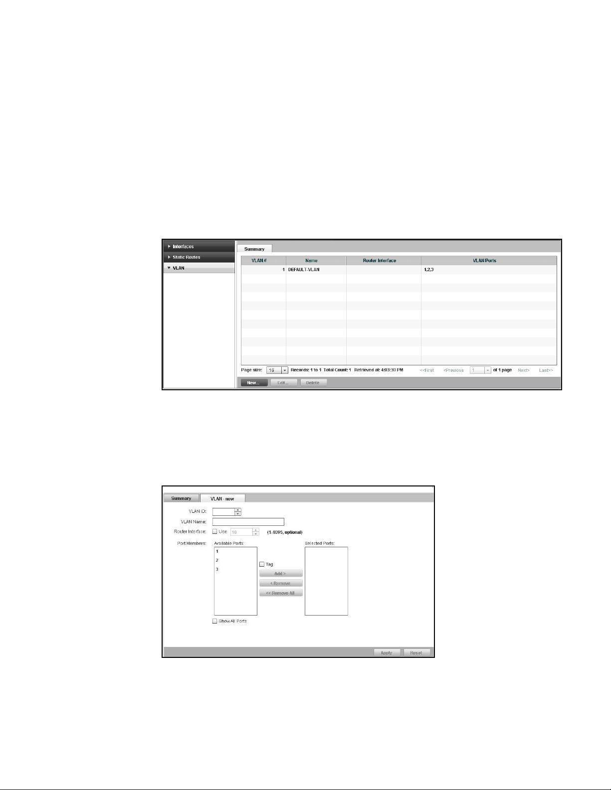
Configuring VLANs
6
Configuring VLANs
You can configure two types of Virtual Local Area Networks (VLANs); port-based VLANs and IP
subnet VLANs. To configure VLAN on the Brocade Virtual ADX, perform the following steps within
the Configure tab.
1. Click Network on the menu bar.
2. From the sidebar, select VLAN.
The Summary page is displayed, as shown in Figure 50.
FIGURE 50 VLAN summary
The Summary page displays a list of configured VLANs. Each entry in the list includes VLAN
name, router interface, and VLAN ports.
3. Click New at the bottom of the Summary page.
The VLAN - new page tab is displayed, as shown in Figure 51.
FIGURE 51 Configuring a VLAN
62 Brocade Virtual ADX Graphical User Interface Guide
53-1003242-01
Page 75

Configuring VLANs
NOTE
4. Provide the following information:
• VLAN: Select the VLAN from the list.
• VLAN Name: Enter the name of the VLAN. The name can contain 16 alphanumeric
characters and you can use blank spaces in the name if you enclose the name in double
quotes.
• Router Interface: Select the Use check box for the routing interface to locally route the IP
packets from an IP subnet VLAN to the port-based VLAN on the same router. The range is
from 1 through 4095. The default value is 16.
5. Under Port Members, do the following tasks:
• Tag : Select the check box only if a port connecting the Brocade Virtual ADXs is a member
of one or more port-based VLAN.
• Select the ports from the Available Ports list and click Add to add the ports to the Selected
Ports list.
To remove a port from th e Selected Ports list, click Remove. To remove all the ports from the
selected list, click Remove All.
6. Click Apply to save your entries.
6
Click Reset to revert the configuration to the previous configured values.
To modify the configured VLAN information, in the Summary table, select an entry and click
Edit or double-click the entry. You can also delete a configuration by clicking Delete.
For more information on the VLAN configuration, refer to the Brocade Virtual ADX Switch and
Router Guide.
Brocade Virtual ADX Graphical User Interface Guide 63
53-1003242-01
Page 76

Configuring VLANs
6
64 Brocade Virtual ADX Graphical User Interface Guide
53-1003242-01
Page 77

Chapter
Traffic Settings
In this chapter
•Global traffic settings . . . . . . . . . . . . . . . . . . . . . . . . . . . . . . . . . . . . . . . . . . . 65
•Virtual servers . . . . . . . . . . . . . . . . . . . . . . . . . . . . . . . . . . . . . . . . . . . . . . . . . 67
•Real servers . . . . . . . . . . . . . . . . . . . . . . . . . . . . . . . . . . . . . . . . . . . . . . . . . . . 78
•Source NAT IPs. . . . . . . . . . . . . . . . . . . . . . . . . . . . . . . . . . . . . . . . . . . . . . . . . 89
•Health checks . . . . . . . . . . . . . . . . . . . . . . . . . . . . . . . . . . . . . . . . . . . . . . . . . 91
•Content switching . . . . . . . . . . . . . . . . . . . . . . . . . . . . . . . . . . . . . . . . . . . . . 106
•OpenScript . . . . . . . . . . . . . . . . . . . . . . . . . . . . . . . . . . . . . . . . . . . . . . . . . . . 125
Global traffic settings
To globally configure the traffic settings in the Brocade Virtual ADX, perform the following steps
within the Configure tab.
7
1. Click Tr affic on the menu bar.
2. From the sidebar, select Global Settings.
The Basic settings in the Global Settings page is displayed, as shown in Figure 52.
FIGURE 52 Configuring basic global settings
For more information on global settings, refer to the Brocade Virtual ADX Server Load
Balancing Guide.
Brocade Virtual ADX Graphical User Interface Guide 65
53-1003242-01
Page 78

Global traffic settings
7
3. For the Basic settings, provide the following information:
• Load Balancing Predictor: Select the algorithm to determine the traffic distribution among
the real servers. The algorithm can be one of the following:
• None — No load balancing predictor is selected.
• Least Connections — Sends the request to the real server that currently has the fewest
active connections with clients.
• Round Robin — Directs the service requests to the next server if a server fails, and
treats all servers equally regardless of the number of connections.
• Weighted — Distributes the service requests by allocating all the required connections
sequentially to the servers with a higher weight value first.
• Enhanced Weighted — Distributes the service requests by allocating all the required
connections sequentially to the servers until each real server has connections equal
to its assigned weight.
• Weighted Round Robin — Schedules a proportional share of the bandwidth when all
servers are active, and redistributes bandwidth if the bandwidth has been reserved by
an inactive real server.
• Weighted Round Robin Static — Distributes the service requests based on a
configured weight value and system capacity.
• Response Time — Distributes the service requests among real servers based on a
dynamic weight value derived from the response time of health check packets.
• TCP Age: Specify the number of minutes the Brocade Virtual ADX allows a TCP connection
to remain inactive before closing the connection. The range is from 2 through 60 minutes.
The default is 30 minutes.
• UDP Age: Specify the number of minutes the Brocade Virtual ADX allows a UDP connection
to remain inactive before closing the connection. The range is from 2 through 60 minutes.
The default is 5 minutes.
• Sticky Age: Specify the number of minutes a sticky server connection can remain inactive
before aging out. The range is from 2 through 60 minutes. The default is 5 minutes.
• Clock Scale: Enter a value to adjust the clock scale for configurations that require TCP or
UDP timeouts longer than the maximum value. The range is from 1 through 24. The default
is 1. For example, when you set the clock scale to 2, then a TCP age of 60 minutes would
be equivalent to 120 minutes.
• Source NAT: Select Enable check box to globally enable the source NAT on the real servers.
• Reassign Threshold: Select Enable check box to enable the reassign threshold (default
setting). Enter the SYN ACK threshold that specifies the number of contiguous
unacknowledged SYN ACKs accumulated for a real server, before determining that the real
server is inactive. The range is from 6 through 4000. The default is 20.
• Force Deletion: Select Enable check box to force the existing SLB connections to be
terminated within two minutes. By default, when a service is disabled or deleted, the
Brocade Virtual ADX does not send new connections to the real servers for that service.
However, the Brocade Virtual ADX does allow existing connections to complete normally,
however long that takes.
• Tra c k Gro u p Unbin d Wait All: Select Enable check box to allow track ports in a track port
group to unbind gracefully after the unbinding of the track group lead port. By default,
when you unbind a port that is the lead port in a track port group, all the ports that track
the lead port also are immediately unbound.
66 Brocade Virtual ADX Graphical User Interface Guide
53-1003242-01
Page 79

Virtual servers
4. Click Apply to save your entries.
Click Reset to revert the configuration to the previous configured values.
5. To configure the TCP options settings when the SYN cookie feature is enabled, click TCP
Options.
The TCP Options settings in the Global Settings page is displayed, as shown in Figure 53.
FIGURE 53 Configuring TCP Options global settings
7
6. Provide the following information:
Virtual servers
A virtual server allows you to manage application server resources by handling the changing traffic
requirements without disrupting the service to the end-users.
The Virtual Server page displays a list of the virtual servers configured on the Brocade Virtual ADX.
Each entry includes the virtual server name, IP address of the virtual server, virtual server port,
admin state, predictor, and status.
To configure a virtual server, perform the following steps within the Configure tab.
1. Click Tr affic on the menu bar.
2. From the sidebar, select Virtual Server.
When a client sends a SYN with a TCP option to the Virtual ADX, the Virtual ADX replies with a
SYN-ACK with a TCP option if the corresponding TCP option is enabled. Otherwise, the Virtual
ADX ignores the TCP options.
• Sack: Select the Enable check box to enable the SACK TCP option to send a selective
acknowledgment.
• Timestamp: Select the Enable check box to enable timestamp TCP option to send a
timestamp in the acknowledgement.
• Window Scale: Specify the window scale factor. Enter a number from 0 to 14.
The Virtual Server page is displayed, as shown in Figure 54.
Brocade Virtual ADX Graphical User Interface Guide 67
53-1003242-01
Page 80

7
Virtual servers
FIGURE 54 Virtual Server tab
3. Click the New button to navigate to the Virtual Server - new tab and configure a new virtual
server.
Creating a virtual server
A virtual server acts as a front end for the application server for distributing the service requests to
the active real servers. When a client sends a TCP or UDP requests to an application port in the
virtual server, the Brocade Virtual ADX identifies one of the back-end application servers (real
servers) based on the configured load balancing method and forwards the client request to the
identified server.
To configure a basic virtual server on the Brocade Virtual ADX, perform the following steps within
the Configure tab.
1. Click Tr affic on the menu bar.
2. From the sidebar, select Virtual Server.
The Virtual Server page is displayed, as shown in Figure 54.
FIGURE 55 Virtual server
68 Brocade Virtual ADX Graphical User Interface Guide
53-1003242-01
Page 81

3. Click New at the bottom of the Virtual Server page.
The Virtual Server - new page tab is displayed, as shown in Figure 56.
FIGURE 56 Configuring virtual server
Virtual servers
7
4. Click Basic and provide the following information:
• Virtual Server Name: Enter the name of the virtual server, which distributes the load at the
real server.
• IP Address: Enter the IP address of the virtual server to which the requests are sent. You
can configure both IPv4.
• Description: Optionally, enter the description for the virtual server.
• Admin State: Deselect the Enable check box to disable the virtual server. By default, admin
state is enabled.
• Load Balancing Predictor: Select a load balancing algorithm from the list to determine the
load distribution among real servers; for example, Weighted Round Robin.
• OID Entry ID: Enter the SNMP object ID value that represents the weight of the real server.
• Max Value: Enter the maximum value for the dynamic weighting. The range is from 0
through 4,294,967,295.
• TOS Marking: Enter the value for the TOS Marking. The range is from 1 through 63.
• Health Check Layer3 DSR: This option is enable when you enter a value for the TOS
Marking. Click the check box to ensure that the health check reply packets will be sent
back to the VIP on the Brocade Virtual ADX. If you configure TOS marking without this
option, if a reply packet has the VIP as its source IP address, health checks will fail and the
packet will be dropped. The TOS marking with this option implicitly enables DSR
fast-delete, expediting the deletion of DSR SLB sessions when the Brocade Virtual ADX
receives a first TCP FIN message from a client.
Brocade Virtual ADX Graphical User Interface Guide 69
53-1003242-01
Page 82

7
Virtual servers
• Under Rate Limiting, you can configure the following information:
• Maximum TCP Connection Rate: Enter the maximum number of TCP connections per
second. There is no default. The maximum connection rate can be from 1 to
4000000.
• Maximum UDP Connection Rate: Enter the maximum number of UDP connections per
second. There is no default. The maximum connection rate can be from 1 to
4000000.
5. Click Advanced to configure the advanced parameters on the virtual server.
The Advanced tab is displayed, as shown in Figure 57.
FIGURE 57 Configuring advanced parameters
6. Provide the following information:
• Tra ckin g: Click one of the following options.
• Tra c k Gro u p — Allows the client to use the same server for applications associated
with the grouped ports, as long as all the ports in the group are active.
• Tra c k Port — Allows the client to use the same server for applications associated with
the grouped ports, as long as the primary port is active.
• None — Allows the client to disable the tracking option on the real server.
• Master Port: Select a master port from the list.
• Tracked Ports: Select tracked ports from the list.
• TCP Age: Specify the number of minutes the Brocade Virtual ADX allows a TCP connection
to remain inactive before closing the connection. The range is from 2 through 60 minutes.
The default value is 30 minutes.
• UDP Age: Specify the number of minutes the Brocade Virtual ADX allows a UDP connection
to remain inactive before closing the connection. The range is from 2 through 60 minutes.
The default value is 5 minutes.
• Sticky Age: Specify the number of minutes a sticky server connection can remain inactive
before aging out. The range is from 2 through 60 minutes. The default value is 5 minutes.
• Under VIP Protection, Select the Enable check box to enable VIP protection.
70 Brocade Virtual ADX Graphical User Interface Guide
53-1003242-01
Page 83

Virtual servers
• Under VIP Route Health Injection, provide the following information:
• Under Advertise VIP Route, provide the following information:
Select the Enable check box to advertise a route in the network containing the virtual
server, even if the virtual server is unavailable.
Select Disable Advertise VIP Route to block advertisement of the network on the
interface. If you do not block advertisement of the network, the Brocade Virtual ADX
advertises a route to the network containing the VIP, even if the VIP itself is
unavailable. After you select this option, the Brocade Virtual ADX advertises only a
host route to the VIP address.
Select Allow Inject Always check box to allow the configuration of the Inject Always
check box. Select the Inject always check box for route injection to occur always.
• Subnet Length: Enter the subnet mask length as an index number. For IPv6, the range
is from 1 through 128. For an IPv4 address, the range is from 1 to 32.
7. Cl i c k Apply to save your entries.
Click Reset to revert the configuration to the previous configured values.
To modify the configured virtual server information, in the summary table, select an entry and
click Edit or double-click the entry. Click Delete to delete a virtual server configuration.
7
For more information on configuring virtual servers, refer to the Brocade Virtual ADX Server Load
Balancing Guide.
Creating a virtual server port
After defining the virtual server, you can add TCP or UDP ports to the virtual servers for receiving
service requests from the client.
To configure a virtual server port on the Brocade Virtual ADX, perform the following steps within the
Configure tab.
1. Click Traf f ic on the menu bar.
2. From the sidebar, select Virtual Servers.
The Virtual Servers page is displayed.
Brocade Virtual ADX Graphical User Interface Guide 71
53-1003242-01
Page 84

7
Virtual servers
3. Select a virtual server from the list in Virtual Servers table and click Ports.
The Virtual Server Ports page tab is displayed, as shown in Figure 58.
FIGURE 58 Virtual server ports
The Virtual Server Ports page displayed a list of configured virtual server ports. Each entry in
the list includes port name, runtime state, protocol, backup, and heath check status.
4. Click New at the bottom of the Virtual Server Ports page. The Basic tab is displayed, as shown
in Figure 59.
FIGURE 59 Configuring virtual server ports
5. Under the Basic tab, provide the following information:
• Virtual Server Name: Enter the name of the virtual server.
• Port: Select the port you want to add to the virtual server.
• Admin State: Deselect the Enable check box to disable the virtual server port. By default,
admin state is enabled.
72 Brocade Virtual ADX Graphical User Interface Guide
53-1003242-01
Page 85

Virtual servers
7
• TCP/UDP: Click one of the following options:
• TCP — To enable only the TCP traffic to pass through the real server.
• UDP — To enable only the UDP traffic to pass through the real server.
• Both — To enable both the TCP and UDP traffic to pass through the real server.
• DSR: For Direct Server Return (DSR), select the following check boxes based on the
requirement:
• Enable — To enable the real server to send the return traffic directly to the client.
• No DSR Fast Delete — To disable DSR fast delete and place the sessions in a deletion
queue upon receiving two FINs from a client. By default, DSR fast delete places a
session in a deletion queue upon receiving the first FIN from a client and deletes the
session in eight seconds instead of the standard two minute FIN session age. Brocade
recommends the default setting.
• Stateless: Select the following check boxes based on the requirement:
• Enable all — To enable stateless operation for both TCP and UDP protocol.
• TCP Transport — To restrict stateless operation to the TCP protocol.
• UDP Transport — To restrict stateless operation to the UDP protocol.
• Disable Hashing — To disable the stateless SLB hashing algorithm for the port.
• CSW: Select the following check boxes based on the requirement:
• Enable — To enable Layer 7 content switching on the virtual server.
• CSW Policy — To select the CSW policy you want to add to the virtual server.
• Custom Health Check: Select a customized health check from the list.
• Port Policy: Select a port policy from the list.
• TCP Age: Specify the number of minutes the Brocade Virtual ADX allows a TCP connection
to remain inactive before closing the connection. The range is from 2 through 60 minutes.
The default value is 30 minutes.
• UDP Age: Specify the number of minutes the Brocade Virtual ADX allows an UDP
connection to remain inactive before closing the connection. The range is from 2 through
60 minutes. The default is 5 minutes. Select the UDP Fast Age and UDP Normal Age check
boxes based on the requirement.
• Syn Proxy MSS: Enter the value for the SYN-Proxy MSS. The range is from 64 through
9126. Note that the SYN-Proxy enabled checkbox for the IP interface must be selected for
this control to be active.
6. Click the Stickiness tab to enable a sticky connection on the TCP or UDP virtual server port.
The Stickiness tab is displayed, as shown in Figure 60.
Brocade Virtual ADX Graphical User Interface Guide 73
53-1003242-01
Page 86

7
Virtual servers
FIGURE 60 Configuring stickiness parameters
7. Provide the following information:
• Stickiness: Click Enable to enable a sticky connection on the virtual server ports, when a
service request by a client mandates a series of sequential TCP or UDP port connections to
be served by the same real server. Select the following options based on the requirement.
• Sticky To Server Group: Select the check box to enable sticky connections to be load
balanced among servers in the same group.
• Group Sticky Failover: Select the check box to send connections to a different
reachable group, when the connection with an entire server group is unreachable.
• Sticky ACL: Select the check box to ensure that subsequent packets from the same
client reaches the same real server.
• ACL ID: Enter the ID of an Access Control List (ACL) that specifies a permit action for
the traffic from specified source IP address, before source NAT is performed. The
range is from 1 through 65,535. The default value is 1.
• Active Primary Override Sticky Session: Select the check box to enable the Active
Primary Override Sticky Session, sending new connections for the port to the primary
server when it comes back up, even though there is a sticky session to the backup
server.
• Persistent Hash: Click Enable to evenly distribute hash assignments and enable a client to
direct the request to the same real server. Click one of the following options:
• Clear Hash Bucket on Change: Allows to clear the entire persistent hash table, when a
new server comes up.
• Reassign Hash Bucket on Change: Allows to calculate the number of hash entries
allocated to each existing server and reassign some of the entries to the new server.
• Sticky Based on Subnet: Click Enable to send all requests originating from a given subnet
to the same real server.
• Subnet Mask: Enter the subnet mask that is used for the stickiness.
• No Stickiness: Click Enable to disable stickiness on the virtual server port.
8. Click Advanced tab to configure the advanced parameters for the virtual server port. The
Advanced tab is displayed, as shown in Figure 61.
74 Brocade Virtual ADX Graphical User Interface Guide
53-1003242-01
Page 87

FIGURE 61 Configuring advanced parameters
9. Provide the following information:
• Under Connection Management, enter the following information:
• TCP Offload: Click Enable to allow a request from one connection on the client side to
reuse any established connection on the sever side. Note that CSW must be enabled.
• Keepalive Age: Specifies how many minutes a connection on the server side can be
kept alive. The range is from 2 through 60 minutes. The default value is 2 minutes.
• Max Transactions: Specifies the maximum number of HTTP transactions that can be
completed on a connection on the server side. The range is from 1 through
4,294,967,295. The default value is 1.
• Client Keepalive: Click Enable to reuse the connection on the client side.
• None: Click None to disable the TCP offload and client keepalive functionality.
• Under Other Settings, provide the following information:
• Use Server Backup: Select the check box to enable a VIP to use the servers
designated as backups only as backups, and use the other servers as the
load-balancing servers.
• Keep Backup Active: Select the check box to configure the VIP and application port to
continue using the backup servers even after the primary servers become available
again.
• Enable Spoofing: Select the check box to mark the input interface of the connection.
Later any response traffic for the session will be forwarded using this information
regardless of any other route configured.
• Enable Port Translation: Select the check box to translate the application port number
requested by the client to the application port number you specify on the virtual server
when you bind it to the real server.
• Send Reset on Port Fail: Select the check box to reset the connection for an
unavailable application on a real server in addition to redirecting future requests away
from this real server if the port fails.
• Use Alias Port State: Select the check box to perform SLB based on an alias port state.
• Concurrent: Select the check box to allow a client to have sessions on different
application ports on the same real server at the same time.
Virtual servers
7
Brocade Virtual ADX Graphical User Interface Guide 75
53-1003242-01
Page 88

7
Virtual servers
• Enable Server Group Failover: Select the check box to direct the HTTP request to one
of the other server groups bound to the virtual servers service, when the servers in
that server group are not available.
• Windows Terminal Server Port: Allows you to reconnect when disconnected from an
already established connection to the session directory on the Windows 2003
terminal server.
• Smooth Factor for Response Time Predictor: Enter the smooth factor value the server
response time calculation uses. You can specify a number from 1 to 99. The default is
60.
10. Click Apply to save your entries.
Click Reset to revert the configuration to the previous configured values.
To modify the configured virtual server ports, in the summary table, select an entry and click
Edit or double-click the entry. Click Delete to delete a virtual server port configuration.
For more information on configuring virtual server ports, refer to the Brocade Virtual ADX Server
Load Balancing Guide.
Binding the virtual server port
To bind a virtual server port to a real port on the Brocade Virtual ADX, perform the following steps
within the Configure tab.
1. Click Traf f ic on the menu bar.
2. From the sidebar, select Virtual Servers.
3. Select a virtual server from the list in the Virtual Servers page and click Bindings.
The binding page is displayed, as shown in Figure 62.
FIGURE 62 Binding virtual server ports
4. Select the VIPs or ports you want to bind from the Available RS-Ports list and click Bind to move
them to the Bound RS-Ports list.
To unbind the ports, select the ports you want to unbind from the Bound RS-Ports list and click
Unbind. To bind or unbind all the ports, click Bind All or Unbind All.
For more information on binding virtual server ports, refer to the Brocade Virtual ADX Server Load
Balancing Guide.
76 Brocade Virtual ADX Graphical User Interface Guide
53-1003242-01
Page 89

Virtual servers
7
Enabling or disabling a virtual server
You can enable or disable a virtual server from the Virtual Servers page.
To enable or disable a virtual server on the Brocade Virtual ADX, perform the following steps within
the Configure tab.
1. Click Traf f ic on the menu bar.
2. From the sidebar, select Virtual Servers.
The list of the virtual servers in the system is displayed on the main page, as shown in
Figure 63.
FIGURE 63 Enabling a virtual server
3. Select a virtual server from the Virtual Servers page and perform one of the following actions:
• Click Enable at the bottom of the Virtual Servers page to enable the virtual server.
• Click Disable to disable the virtual server.
For more information on enabling or disabling virtual servers, refer to the Brocade Virtual ADX
Server Load Balancing Guide.
Virtual server port configuration summary
The Virtual Server Ports tab displays ports configured on a device selected from the Virtual Server
tab.
Perform the following steps within the Configure tab to view ports configured on virtual servers,
displayed on the Virtual Server Ports tab.
1. Click Traf f ic on the menu bar.
2. From the sidebar, select Virtual Servers.
The list of the virtual servers in the system is displayed on the main page, as shown in
Figure 63.
3. Select a virtual server from the Virtual Servers page.
4. Click the Ports button.
5. The Virtual Server Ports page is displayed for the specific virtual server selected in Step 3.
Brocade Virtual ADX Graphical User Interface Guide 77
53-1003242-01
Page 90

Real servers
7
Real servers
6. Click the New button to display the Virtual Server Port - new page and use this page to
configure a virtual server port.
Real servers are the actual application servers that handles all the client service requests. To view
basic real servers configured on the Brocade Virtual ADX, perform the following steps within the
Configure tab.
1. Click Traf f ic on the menu bar.
2. From the sidebar, select Real Servers.
The Real Servers page is displayed, as shown in Figure 64.
FIGURE 64 Real server summary
The Real Servers page displays a list of all the configured real servers. Each entry in the list
includes the real server name, IP address, port, and status.
78 Brocade Virtual ADX Graphical User Interface Guide
53-1003242-01
Page 91

Real servers
7
Creating a basic real server
To apply SLB configuration, you must create a basic real server. After you create the basic real
server, you must map the real server to the virtual server to distribute the requests from the client
among the back-end application servers.
To configure a basic real server on the Brocade Virtual ADX, perform the following steps within the
Configure tab.
1. Click Traf f ic on the menu bar.
2. From the sidebar, select Real Servers.
The Real Servers page is displayed, as shown in Figure 64.
The Real Servers page displays a list of all the configured real servers. Each entry in the list
includes the real server name, IP address, port, and status.
3. Click New at the bottom of the Real Servers page.
The Real Sever - new page tab is displayed. By default, Basic configuration tab is displayed, as
shown in Figure 65.
FIGURE 65 Configuring real server basic parameters
4. Under Basic tab, enter the following information:
• Real Server Name: Enter the name of the real server.
• IP Address: Enter the IP address of the real server. You can configure both IPv4.
• Description: Optionally, enter a description for the real server.
• Alias Name: Optionally, enter the name of the alias.
• Admin State: Click the Enable check box to disable the real server. By default, the real
server is enabled.
• Remote: Select the Enable (only editable at creation time) check box to designate the real
server to be a remote server, if the server is attached through one or more router hops.
You can configure only during the creation of the real server.
Brocade Virtual ADX Graphical User Interface Guide 79
53-1003242-01
Page 92

7
Real servers
• Backup: Select the Enable check box to designate the real server to be a backup server if
all the primary servers are unavailable for the requested application.
• Use Learned MAC Address: Select the Enable check box to enable MAC Address learning
on the real server.
5. Click Apply to save your entries.
Click Reset to revert the configuration to the previous configured values.
To modify the configured real server information, in the summary table, select an entry and
click Edit or double-click the entry. Click Delete to delete a real server configuration.
For more information on configuring real servers, refer to the Brocade Virtual ADX Server Load
Balancing Guide.
Setting predictors and advanced settings for real servers
To configure predictors for real servers on the Brocade Virtual ADX, perform the following steps
within the Configure tab.
1. Click Tr affic on the menu bar.
2. From the sidebar, select Real Servers.
3. Click New at the bottom of the Real Servers page.
4. Click the Predictors tab.
The Predictors tab is displayed, as shown in Figure 66.
FIGURE 66 Configuring predictors parameters
5. Under Dynamic Weighted, enter the following information:
• Port: Enter the SNMP request host port.
• Community Name: Enter an SNMP community name to restrict SNMP access to all the real
servers.
• Entry ID: Enter the SNMP request entry identification in the fields and the corresponding
SNMP Object ID (OID) value in the SNMP Request OID fields.
80 Brocade Virtual ADX Graphical User Interface Guide
53-1003242-01
Page 93

Real servers
NOTE
6. Under Enhanced Weight, enter the following information:
Least Connection Weight: Enter the weight of the real server relative to other real servers in
terms of the number of connections on the server. The weight is based on the number of
session table entries for TCP or UDP sessions with the real server.
7. Cl ic k th e Advanced tab to configure advanced parameters for the real server configuration.
The Advanced tab is displayed, as shown in Figure 67.
FIGURE 67 Configuring advanced parameters
7
8. Provide the following information:
• Health Check Tracking: Click one of the following options:
If any service port is down for a real server, the Brocade Virtual ADX does not consider the
track port group or track port configuration on the real server for load balancing. You must
configure every port in a track port group or track port configuration to be “sticky” and
bind them to the real server.
• Tra c k Gro u p: Allows the Brocade Virtual ADX to send client requests for applications
within a group of up to eight ports to the same real server, regardless of which
application the client requests first. Whenever a client attempts to connect to a port
within the port group, the Brocade Virtual ADX ensures that all ports in the group are
active before granting the connection.
• Tra c k Port: Allows the Brocade Virtual ADX to send all client requests for a specific set
of TCP or UDP ports to the same real server as a master TCP or UDP port grouped with
up to four other ports. The tracking applies only to the master port.
• None: Disables track group and track port health check tracking. By default, health
check tracking is disabled.
• Master Port: For the Track Po r t option only, choose the port as the master port.
• Tra c k Ports: For the Tr ack Gro u p option, choose up to eight TCP or UDP ports. A port can be
part of only one track port group. For the Track Po r t option, choose up to four TCP or UDP
ports.
Brocade Virtual ADX Graphical User Interface Guide 81
53-1003242-01
Page 94

7
Real servers
• Ping Health Check: Select the Enable check box to enable Layer 3 health checks to the
real server IP addresses.
• Source NAT: Select the Enable check box to allow the device to use a source IP address as
the source for packets sent to the real server.
• Source-NAT ACL: Select the check box to configure the device to apply source NAT for the
traffic received from specified source IP addresses, by creating an access control list,
which specifies a permit action for the traffic from the source IP address.
• ACL ID: Enter the identifier for the access list in the source NAT. The range is from 1
through 99. The default value is 1.
9. Under Rate Limiting, provide the following information:
• Maximum Connections: Enter the maximum number of sessions the device will maintain
in its session table. The range is from 1 through 2000000.
• Maximum TCP Connection Rate: Enter the maximum number of TCP connections per
second. The range is from 1 through 4000000.
• Maximum UDP Connection Rate: Enter the maximum number of UDP connections per
second. The range is from 1 through 4000000.
10. Click Apply to save your entries.
Click Reset to revert the configuration to the previous configured values.
For more information on configuring real servers, refer to the Brocade Virtual ADX Server Load
Balancing Guide.
Real server port configuration summary
The Real Servers Ports tab displays a list of real server ports configured on the Brocade Virtual
ADX. Each entry includes the port name, Admin status, run-time state, Slow Start status, backup,
and health check status.
To view the ports for a real server configured on the Brocade Virtual ADX, perform the following
steps within the Configure tab.
1. Click Tr affic on the menu bar.
2. From the sidebar, select Real Servers.
The Real Server page is displayed, as shown in Figure 64.
3. Select a real server to perform the following actions:
• Click the New button to display the Configure Real Server - new tab and configure a real
server.
• Click the Edit button to open the Edit Real Server tab and edit parameters for the selected
real server entry.
82 Brocade Virtual ADX Graphical User Interface Guide
53-1003242-01
Page 95

Real servers
4. Click the Ports button to display the Real Server Ports tab for the selected real server entry.
FIGURE 68 Real Server ports page
From this tab, you can add, edit, enable, disable or monitor a real server port.
7
Creating a real server port
To configure a basic real server port on the Brocade Virtual ADX, perform the following steps within
the Configure tab.
1. Click Tr affic on the menu bar.
2. From the sidebar, select Real Servers.
3. Select the real server from the list in the Real Servers page and click Port.
The Real Server Ports page tab is displayed, as shown in Figure 68.
4. Click New at the bottom of the Real Server Ports page.
The Basic configuration tab is displayed, as shown in Figure 69.
Brocade Virtual ADX Graphical User Interface Guide 83
53-1003242-01
Page 96

7
Real servers
FIGURE 69 Configuring real server port
5. Under Basic, provide the following information:
• Real Server Name: Displays the name of the real server.
• Port: Select an application port from the list to add under the real servers.
• Admin State: Select the appropriate check boxes to enable the port, set the port as
backup, and clear the sessions when the port is up.
• Server ID: Enter the ID of the real server to forward the packets matching a specified rule
to a specified real server or server group. The range is from 1024 through 1535. The
default is 1024.
• Group ID: Enter the four group ID range in the corresponding fields to ensure that packets
matching the rule go to the same real server within the server group. The range is from 0
through 1023.
• Slow Start ID: Select a number from the list to configure the device to handle limited
number of connection at first and gradually increase the connections until the maximum is
reached.
• Under Rate Limiting, provide the following information:
• Maximum Connections: Enter the maximum number of connections that the client can
setup. The range is from 1 through 2,000,000.
• Maximum TCP Connection Rate: Enter the maximum number of TCP connections per
second. The range is from 1 through 4,294,967,295.
• Maximum UDP Connection Rate: Enter the maximum number of UDP connections per
second. The range is from 1 through 4,294,967,295.
6. Click Apply to save your entries.
Click Reset to revert the configuration to the previous configured values.
To modify the configured real server ports, in the summary table, select an entry and click Edit
or double-click the entry. You can also delete a configuration by clicking Delete.
For more information on configuring real server ports, refer to the Brocade Virtual ADX Server Load
Balancing Guide.
84 Brocade Virtual ADX Graphical User Interface Guide
53-1003242-01
Page 97

Real servers
Configuring health check parameters for a real server port
To configure the health check parameters for a real server port on the Brocade Virtual ADX,
perform the following steps within the Configure tab.
1. Click Traf f ic on the menu bar.
2. From the sidebar, select Real Servers.
3. Select the real server from the list in Real Servers page and click Port.
4. Click New at the bottom of the Real Servers page.
5. Click Health Check tab.
The Health Check page is displayed, as shown in Figure 70.
FIGURE 70 Configuring health check parameters
7
6. Provide the following information:
• Periodic Health Check: Select the Enable check box to enable the Layer 3 health check for
the local real server.
• Select the L4 Only check box to enable a Layer 4 check, if the application port is not one of
the applications that is known to the Brocade Virtual ADX.
• Element Health Check: Select a health check on the Brocade Virtual ADX to allow a health
check that is customized for a given application server.
• Port Policy: Select a port policy from the list to reduce the configuration required for health
checks and provide more flexibility while configuring health checks.
• Content Check Match List: Select a match list to be used for content check for custom
ports only.
• ASCII String: Enter the ASCII string to send for custom ports only.
• Bringup Intervals: Enter the Layer 4 and Layer 7 bringup intervals to enable the health
check policy during initial bringup of the server in seconds. The range is from 1 through
255 seconds.
7. Under Specific settings to HTTP, enter the following information:
Brocade Virtual ADX Graphical User Interface Guide 85
53-1003242-01
Page 98

7
Server groups
• URL: Enter the URL name to specify whether the HTTP health check performs a GET or
HEAD request while customizing the Layer 7 information sent with the health check.
• Status Codes: Enter the status code for the four groups to change the HTTP status codes
that the Brocade Virtual ADX accepts as valid responses. The range is from 100 through
999.
• Content Match: Select the content match from the list to attach a match list for an HTTP
content verification health check to the real server.
8. Click Apply to save your entries.
Click Reset to revert the configuration to the previous configured values.
To modify the configured real server ports, in the summary table, select an entry and click Edit
or double-click the entry. You can also delete a configuration by clicking Delete.
For more information on configuring health check on real servers ports, refer to the Brocade Virtual
ADX Server Load Balancing Guide.
Enabling or disabling a real server
You can enable or disable a real server from the Real Servers page.
To enable or disable a real server on the Brocade Virtual ADX, perform the following steps within
the Configure tab.
1. Click Traf f ic on the menu bar.
2. From the sidebar, select Real Servers.
3. Select a real server from the list and click one of the following buttons at the bottom of the
For more information on enabling or disabling real servers, refer to the Brocade Virtual ADX Server
Load Balancing Guide.
Server groups
A server group can contain one or more real servers. If there is more than one real server in a
server group, requests are load balanced across all the servers in the group. To assign real servers
to server groups, you establish the IP address of each real server and specify the server groups to
which it belongs.
To create a real server group, perform the following steps within the Configure tab.
The list of the real servers in the system is displayed on the Real Servers page.
Real Servers page:
• Click Enable at the bottom of the Real Servers page to enable the real server.
• Click Disable to disable the real server.
1. Click Tr affic on the menu bar.
2. From the sidebar, select Server Groups.
The Server Groups page is displayed, as shown in Figure 71.
86 Brocade Virtual ADX Graphical User Interface Guide
53-1003242-01
Page 99

Server groups
7
FIGURE 71 Server group summary
The Server Groups page displays a list of configured real server groups. Each entry in the list
includes name of the group, ports added, bound virtual server and ports, and number of real
servers.
3. Click New at the bottom of the Server Groups page.
The Configure Server Group page tab is displayed, as shown in Figure 72.
FIGURE 72 Configuring a server group
4. Provide the following information:
• Server Group Name: Enter the name of the server group.
• Add Real Servers: Select the real servers from the Available Servers list and click Add to
move the real servers to the Selected Servers list to add server group.
To modify the configured server groups, in the summary table, select an entry and click Edit or
double-click the entry. You can also delete a configuration by clicking Delete or launch the virtual
servers that are bound to the server group by clicking Virtual Servers.
For more information on configuring server groups, refer to the Brocade Virtual ADX Server Load
Balancing Guide.
Brocade Virtual ADX Graphical User Interface Guide 87
53-1003242-01
Page 100

7
Server groups
Binding a server group
To bind a server group with a virtual server port on the Brocade Virtual ADX, perform the following
steps within the Configure tab.
1. Click Tr affic on the menu bar.
2. From the sidebar, select Server Groups.
The Server Groups page is displayed.
3. Select a server group entry from the list in the Server Group page and click Bind.
The Virtual Server Bindings page is displayed, as shown in Figure 73.
FIGURE 73 Binding server groups
4. Provide the following information:
• Server Group Port: Select the port of the server group to bind with the virtual server port.
• Virtual Server: Select the virtual server that you want to bind to the server group.
• Virtual Port: Select the virtual server port to which you want to bind the server group port.
5. Click OK to bind the virtual server to the real server groups.
For more information on binding virtual servers to the server group, refer to the Brocade Virtual
ADX Server Load Balancing Guide.
88 Brocade Virtual ADX Graphical User Interface Guide
53-1003242-01
 Loading...