

Page 1

53-1002563-04
5
17 April 2014
Brocade VDX 8770-4
Hardware Reference Manual
®
Page 2
Copyright © 2012-2014 Brocade Communications Systems, Inc. All Rights Reserved.
Brocade, the B-wing symbol, Brocade Assurance, ADX, AnyIO, DCX, Fabric OS, FastIron, HyperEdge, ICX, MLX, MyBrocade, NetIron,
OpenScript, VCS, VDX, and Vyatta are registered trademarks, and The Effortless Network and the On-Demand Data Center are
trademarks of Brocade Communications Systems, Inc., in the United States and in other countries. Other brands and product
names mentioned may be trademarks of others.
Notice: This document is for informational purposes only and does not set forth any warranty, expressed or implied, concerning
any equipment, equipment feature, or service offered or to be offered by Brocade. Brocade reserves the right to make changes to
this document at any time, without notice, and assumes no responsibility for its use. This informational document describes
features that may not be currently available. Contact a Brocade sales office for information on feature and product availability.
Export of technical data contained in this document may require an export license from the United States government.
The authors and Brocade Communications Systems, Inc. assume no liability or responsibility to any person or entity with respect
to the accuracy of this document or any loss, cost, liability, or damages arising from the information contained herein or the
computer programs that accompany it.
The product described by this document may contain open source software covered by the GNU General Public License or other
open source license agreements. To find out which open source software is included in Brocade products, view the licensing
terms applicable to the open source software, and obtain a copy of the programming source code, please visit http://
www.brocade.com/support/oscd.
Brocade Communications Systems, Incorporated
Corporate and Latin American Headquarters
Brocade Communications Systems, Inc.
130 Holger Way
San Jose, CA 95134
Tel: 1-408-333-8000
Fax: 1-408-333-8101
E-mail: info@brocade.com
European Headquarters
Brocade Communications Switzerland Sàrl
Centre Swissair
Tour B - 4ème étage
29, Route de l'Aéroport
Case Postale 105
CH-1215 Genève 15
Switzerland
Tel: +41 22 799 5640
Fax: +41 22 799 5641
E-mail: emea-info@brocade.com
Asia-Pacific Headquarters
Brocade Communications Systems China HK, Ltd.
No. 1 Guanghua Road
Chao Yang District
Units 2718 and 2818
Beijing 100020, China
Tel: +8610 6588 8888
Fax: +8610 6588 9999
E-mail: china-info@brocade.com
Asia-Pacific Headquarters
Brocade Communications Systems Co., Ltd. (Shenzhen WFOE)
Citic Plaza
No. 233 Tian He Road North
Unit 1308 – 13th Floor
Guangzhou, China
Tel: +8620 3891 2000
Fax: +8620 3891 2111
E-mail: china-info@brocade.com
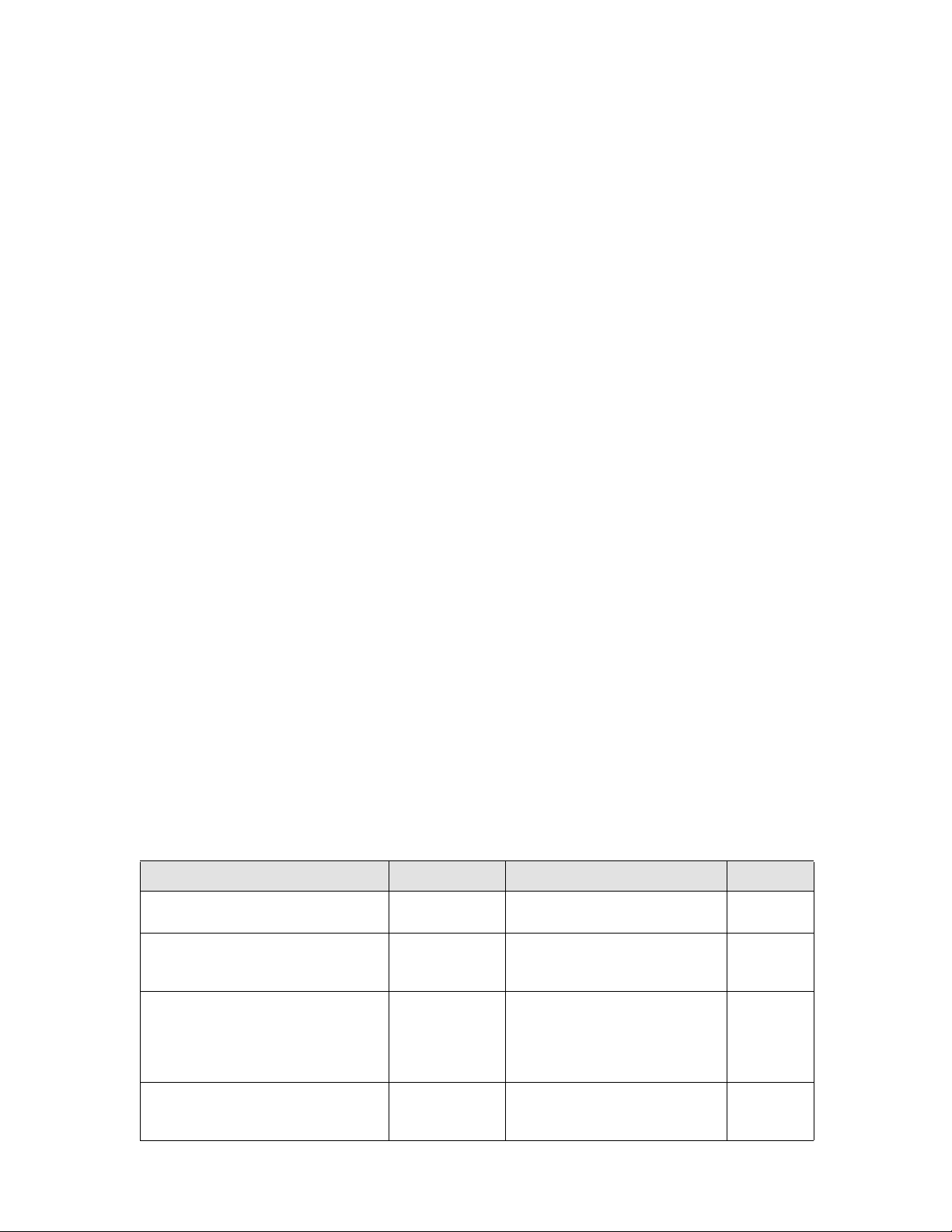
Document History
Title Publication number Summary of changes Date
Brocade VDX 8770-4 Hardware Reference
Manual
Brocade VDX 8770-4 Hardware Reference
Manual
Brocade VDX 8770-4 Hardware Reference
Manual
Brocade VDX 8770-4 Hardware Reference
Manual
53-1002563-01 New document. Sept 2012
53-1002563-02 NEBS GR-1089 installation
requirements added including air filter
replacement procedure.
53-1002563-03 Additional NEBS requirement added
for air filter replacement. Changed
reference to availability of SX and LX
transceivers. Changed LED indication
for Ethernet management link on MM.
53-1002563-04 Added information about 48x10G-T,
27x40 GbE, and 6x100 GbE line
cards.
Mar 2013
Aug 2013
April 2014
Page 3

Contents
DRAFT: BROCADE CONFIDENTIAL
About This Document
How this document is organized . . . . . . . . . . . . . . . . . . . . . . . . . . . . xiii
Supported hardware and software . . . . . . . . . . . . . . . . . . . . . . . . . . xiv
What’s new in this document. . . . . . . . . . . . . . . . . . . . . . . . . . . . . . . xiv
Document conventions. . . . . . . . . . . . . . . . . . . . . . . . . . . . . . . . . . . . xv
Text formatting . . . . . . . . . . . . . . . . . . . . . . . . . . . . . . . . . . . . . . . xv
Command syntax conventions . . . . . . . . . . . . . . . . . . . . . . . . . . xv
Command examples . . . . . . . . . . . . . . . . . . . . . . . . . . . . . . . . . . xvi
Notes, cautions, and warnings . . . . . . . . . . . . . . . . . . . . . . . . . . xvi
Notice to the reader . . . . . . . . . . . . . . . . . . . . . . . . . . . . . . . . . . . . . .xvii
Additional information. . . . . . . . . . . . . . . . . . . . . . . . . . . . . . . . . . . . .xvii
Brocade resources. . . . . . . . . . . . . . . . . . . . . . . . . . . . . . . . . . . xvii
Other industry resources. . . . . . . . . . . . . . . . . . . . . . . . . . . . . . xviii
Getting technical help. . . . . . . . . . . . . . . . . . . . . . . . . . . . . . . . . . . . xviii
Document feedback . . . . . . . . . . . . . . . . . . . . . . . . . . . . . . . . . . . . . . xix
Chapter 1 Brocade VDX 8770-4 Overview
Brocade VDX 8770-4 features . . . . . . . . . . . . . . . . . . . . . . . . . . . . . . . 1
Brocade VDX 8770-4 hardware components . . . . . . . . . . . . . . . . . . . 2
Port side of the Brocade VDX 8770-4. . . . . . . . . . . . . . . . . . . . . . 3
Nonport side of the Brocade VDX 8770-4 . . . . . . . . . . . . . . . . . . 5
Brocade VDX 8770-4 line cards. . . . . . . . . . . . . . . . . . . . . . . . . . . . . . 6
Breakout mode. . . . . . . . . . . . . . . . . . . . . . . . . . . . . . . . . . . . . . . . 6
Trunking . . . . . . . . . . . . . . . . . . . . . . . . . . . . . . . . . . . . . . . . . . . . . 6
27x40 GbE operating modes . . . . . . . . . . . . . . . . . . . . . . . . . . . .7
High availability . . . . . . . . . . . . . . . . . . . . . . . . . . . . . . . . . . . . . . . . . . . 8
Software features . . . . . . . . . . . . . . . . . . . . . . . . . . . . . . . . . . . . . . . . . 9
Layer 2 . . . . . . . . . . . . . . . . . . . . . . . . . . . . . . . . . . . . . . . . . . . . . . 9
Layer 3 . . . . . . . . . . . . . . . . . . . . . . . . . . . . . . . . . . . . . . . . . . . . . . 9
Virtualization . . . . . . . . . . . . . . . . . . . . . . . . . . . . . . . . . . . . . . . . . 9
FCoE . . . . . . . . . . . . . . . . . . . . . . . . . . . . . . . . . . . . . . . . . . . . . . .10
Link aggregration . . . . . . . . . . . . . . . . . . . . . . . . . . . . . . . . . . . . .10
QoS . . . . . . . . . . . . . . . . . . . . . . . . . . . . . . . . . . . . . . . . . . . . . . . .10
Management . . . . . . . . . . . . . . . . . . . . . . . . . . . . . . . . . . . . . . . .10
Licensing. . . . . . . . . . . . . . . . . . . . . . . . . . . . . . . . . . . . . . . . . . . .10
Chapter 2 Installation of the Brocade VDX 8770-4
Time and items required. . . . . . . . . . . . . . . . . . . . . . . . . . . . . . . . . . .13
Brocade VDX 8770-4 Hardware Reference Manual 3
53-1002563-04
Page 4

DRAFT: BROCADE CONFIDENTIAL
Items included with the Brocade VDX 8770-4 . . . . . . . . . . . . . . . . .15
Preparing for the Brocade VDX 8770-4 installation . . . . . . . . . . . . .16
Power specifications . . . . . . . . . . . . . . . . . . . . . . . . . . . . . . . . . .17
Environmental requirements. . . . . . . . . . . . . . . . . . . . . . . . . . . .19
Chassis slots . . . . . . . . . . . . . . . . . . . . . . . . . . . . . . . . . . . . . . . .20
Unpacking and installing the Brocade VDX 8770-4 . . . . . . . . . . . . .20
Port numbering . . . . . . . . . . . . . . . . . . . . . . . . . . . . . . . . . . . . . . . . . .21
Providing power to the Brocade VDX 8770-4 . . . . . . . . . . . . . . . . . .22
Connecting an AC power cord . . . . . . . . . . . . . . . . . . . . . . . . . . .22
Connecting a DC power cord. . . . . . . . . . . . . . . . . . . . . . . . . . . .22
Chapter 3 Configuring the Brocade VDX 8770-4
Preparing to configure the Brocade VDX 8770-4 . . . . . . . . . . . . . . .25
Establishing a serial connection to the Brocade VDX 8770-4 . . . . .26
Logging in to the serial console port . . . . . . . . . . . . . . . . . . . . . . . . .28
Changing the RBridge ID. . . . . . . . . . . . . . . . . . . . . . . . . . . . . . . . . . .28
Assigning permanent passwords . . . . . . . . . . . . . . . . . . . . . . . . . . . .29
Changing the default account passwords . . . . . . . . . . . . . . . . .29
Configuring the IP addresses . . . . . . . . . . . . . . . . . . . . . . . . . . . . . . .29
Setting a static IP address . . . . . . . . . . . . . . . . . . . . . . . . . . . . .30
Logging off the serial console port and disconnecting the
serial cable . . . . . . . . . . . . . . . . . . . . . . . . . . . . . . . . . . . . . . . . . . . . .31
Establishing an Ethernet connection to the Brocade
VDX 8770-4 . . . . . . . . . . . . . . . . . . . . . . . . . . . . . . . . . . . . . . . . . . . . .31
Customizing a host name. . . . . . . . . . . . . . . . . . . . . . . . . . . . . . . . . . 31
Customizing a chassis name . . . . . . . . . . . . . . . . . . . . . . . . . . . . . . .32
Setting the date and time. . . . . . . . . . . . . . . . . . . . . . . . . . . . . . . . . .32
Time zones . . . . . . . . . . . . . . . . . . . . . . . . . . . . . . . . . . . . . . . . . .33
Time synchronization. . . . . . . . . . . . . . . . . . . . . . . . . . . . . . . . . .33
Synchronizing local time using NTP . . . . . . . . . . . . . . . . . . . . . .33
Setting the time zone. . . . . . . . . . . . . . . . . . . . . . . . . . . . . . . . . .34
Setting the clock (date and time) . . . . . . . . . . . . . . . . . . . . . . . .34
Determining installed software licenses . . . . . . . . . . . . . . . . . . . . . .35
Configuring operating modes on 27x40 GbE line cards. . . . . . . . . .35
Saving your changes. . . . . . . . . . . . . . . . . . . . . . . . . . . . . . . . . . . . . .36
Verifying correct operation . . . . . . . . . . . . . . . . . . . . . . . . . . . . . . . . .37
Backing up the configuration . . . . . . . . . . . . . . . . . . . . . . . . . . . . . . . 37
Connecting network devices. . . . . . . . . . . . . . . . . . . . . . . . . . . . . . . .38
Connecting to Ethernet devices . . . . . . . . . . . . . . . . . . . . . . . . .38
Connecting to workstations, servers, or routers . . . . . . . . . . . .38
Connecting a network device to a fiber port . . . . . . . . . . . . . . .38
Testing connectivity . . . . . . . . . . . . . . . . . . . . . . . . . . . . . . . . . . .38
4 Brocade VDX 8770-4 Hardware Reference Manual
53-1002563-04
Page 5

DRAFT: BROCADE CONFIDENTIAL
Installing transceivers and attaching cables. . . . . . . . . . . . . . . . . . .39
Installing SFP and SFP+ transceivers and cables. . . . . . . . . . .39
Installing QSFP transceivers and cables . . . . . . . . . . . . . . . . . .39
Managing cables. . . . . . . . . . . . . . . . . . . . . . . . . . . . . . . . . . . . . . . . .40
Chapter 4 Monitoring System Components
Monitoring overview . . . . . . . . . . . . . . . . . . . . . . . . . . . . . . . . . . . . . . 41
Determining the status of a line card . . . . . . . . . . . . . . . . . . . . . . . . 41
Line card illustrations . . . . . . . . . . . . . . . . . . . . . . . . . . . . . . . . .42
Determining the status of a management module. . . . . . . . . . . . . .49
Determining the status of a system fabric module. . . . . . . . . . . . . . 51
Determining the status of a power supply. . . . . . . . . . . . . . . . . . . . .52
Determining the status of a fan . . . . . . . . . . . . . . . . . . . . . . . . . . . . .53
Determining the status of a CID card . . . . . . . . . . . . . . . . . . . . . . . .55
Chapter 5 Removal and Replacement Procedures
Introduction . . . . . . . . . . . . . . . . . . . . . . . . . . . . . . . . . . . . . . . . . . . . .57
ESD precautions . . . . . . . . . . . . . . . . . . . . . . . . . . . . . . . . . . . . . . . . . 57
Cable management finger assembly removal and replacement. . . 58
Time and items required . . . . . . . . . . . . . . . . . . . . . . . . . . . . . . .58
Removing a cable management finger assembly . . . . . . . . . . .58
Replacing a cable management finger assembly . . . . . . . . . . .59
Line card removal and replacement . . . . . . . . . . . . . . . . . . . . . . . . .59
Time and items required . . . . . . . . . . . . . . . . . . . . . . . . . . . . . . .59
Removing a line card . . . . . . . . . . . . . . . . . . . . . . . . . . . . . . . . . .60
Replacing a line card . . . . . . . . . . . . . . . . . . . . . . . . . . . . . . . . . .61
Management module removal and replacement . . . . . . . . . . . . . . .62
Time and items required . . . . . . . . . . . . . . . . . . . . . . . . . . . . . . .62
Faulty management module indicators . . . . . . . . . . . . . . . . . . .63
Recording critical Brocade VDX 8770-4 information. . . . . . . . . 63
Removing a management module . . . . . . . . . . . . . . . . . . . . . . .63
Replacing a management module . . . . . . . . . . . . . . . . . . . . . . .64
Switch fabric module removal and replacement . . . . . . . . . . . . . . .65
Time and items required . . . . . . . . . . . . . . . . . . . . . . . . . . . . . . .65
Removing a switch fabric module. . . . . . . . . . . . . . . . . . . . . . . .65
Replacing a switch fabric module. . . . . . . . . . . . . . . . . . . . . . . .66
Power supply removal and replacement . . . . . . . . . . . . . . . . . . . . . .67
Time and items required . . . . . . . . . . . . . . . . . . . . . . . . . . . . . . .67
Removing an AC power supply . . . . . . . . . . . . . . . . . . . . . . . . . .67
Replacing an AC power supply . . . . . . . . . . . . . . . . . . . . . . . . . .68
Removing a DC power supply . . . . . . . . . . . . . . . . . . . . . . . . . . .69
Replacing a DC power supply . . . . . . . . . . . . . . . . . . . . . . . . . . .69
Brocade VDX 8770-4 Hardware Reference Manual 5
53-1002563-04
Page 6

DRAFT: BROCADE CONFIDENTIAL
Fan removal and replacement. . . . . . . . . . . . . . . . . . . . . . . . . . . . . .70
Time and items required . . . . . . . . . . . . . . . . . . . . . . . . . . . . . . .70
Removing a fan . . . . . . . . . . . . . . . . . . . . . . . . . . . . . . . . . . . . . .70
Replacing a fan . . . . . . . . . . . . . . . . . . . . . . . . . . . . . . . . . . . . . . 71
Air filter removal and replacement . . . . . . . . . . . . . . . . . . . . . . . . . . 71
Time and items required . . . . . . . . . . . . . . . . . . . . . . . . . . . . . . .72
Replacing the front air filter. . . . . . . . . . . . . . . . . . . . . . . . . . . . .72
Replacing the side air filter . . . . . . . . . . . . . . . . . . . . . . . . . . . . .73
Module filler panel removal and replacement . . . . . . . . . . . . . . . . . 74
Removing a filler panel . . . . . . . . . . . . . . . . . . . . . . . . . . . . . . . . 74
Replacing a filler panel . . . . . . . . . . . . . . . . . . . . . . . . . . . . . . . .75
Chassis ID card removal and replacement . . . . . . . . . . . . . . . . . . . .75
SFP transceiver removal and replacement. . . . . . . . . . . . . . . . . . . . 76
Time and items required . . . . . . . . . . . . . . . . . . . . . . . . . . . . . . .76
Removing a transceiver. . . . . . . . . . . . . . . . . . . . . . . . . . . . . . . . 77
Replacing a transceiver. . . . . . . . . . . . . . . . . . . . . . . . . . . . . . . .78
QSFP transceiver removal and replacement. . . . . . . . . . . . . . . . . . .78
Removing a QSFP transceiver. . . . . . . . . . . . . . . . . . . . . . . . . . .78
Replacing a QSFP transceiver. . . . . . . . . . . . . . . . . . . . . . . . . . .79
Cable routing table . . . . . . . . . . . . . . . . . . . . . . . . . . . . . . . . . . . . . . .79
Appendix A Specifications
General specifications . . . . . . . . . . . . . . . . . . . . . . . . . . . . . . . . . . . .83
System architecture . . . . . . . . . . . . . . . . . . . . . . . . . . . . . . . . . . . . . .84
System size and weight . . . . . . . . . . . . . . . . . . . . . . . . . . . . . . . . . . .84
System module and FRU weights. . . . . . . . . . . . . . . . . . . . . . . . . . . .85
Ethernet port supported optics . . . . . . . . . . . . . . . . . . . . . . . . . . . . .86
Power cords. . . . . . . . . . . . . . . . . . . . . . . . . . . . . . . . . . . . . . . . . . . . .87
Power cord notice. . . . . . . . . . . . . . . . . . . . . . . . . . . . . . . . . . . . .90
Power cord notice (Japan DENAN) . . . . . . . . . . . . . . . . . . . . . . .90
Safety notices . . . . . . . . . . . . . . . . . . . . . . . . . . . . . . . . . . . . . . . . . . .90
NEBS requirements. . . . . . . . . . . . . . . . . . . . . . . . . . . . . . . . . . . . . . .91
Regulatory compliance . . . . . . . . . . . . . . . . . . . . . . . . . . . . . . . . . . . .92
FCC warning (US only) . . . . . . . . . . . . . . . . . . . . . . . . . . . . . . . . .92
KCC statement (Republic of Korea) . . . . . . . . . . . . . . . . . . . . . .92
VCCI statement (Japan). . . . . . . . . . . . . . . . . . . . . . . . . . . . . . . .93
BSMI statement (Taiwan) . . . . . . . . . . . . . . . . . . . . . . . . . . . . . .93
CE statement . . . . . . . . . . . . . . . . . . . . . . . . . . . . . . . . . . . . . . . .93
Canadian requirements. . . . . . . . . . . . . . . . . . . . . . . . . . . . . . . .94
German statement. . . . . . . . . . . . . . . . . . . . . . . . . . . . . . . . . . . .94
Laser compliance. . . . . . . . . . . . . . . . . . . . . . . . . . . . . . . . . . . . .94
Safety agency approvals . . . . . . . . . . . . . . . . . . . . . . . . . . . . . . .94
Regulatory compliance standards . . . . . . . . . . . . . . . . . . . . . . .94
Environmental regulation compliance. . . . . . . . . . . . . . . . . . . . . . . .95
China RoHS . . . . . . . . . . . . . . . . . . . . . . . . . . . . . . . . . . . . . . . . .95
6 Brocade VDX 8770-4 Hardware Reference Manual
53-1002563-04
Page 7

DRAFT: BROCADE CONFIDENTIAL
Appendix B Caution and Danger Notices
Caution notices . . . . . . . . . . . . . . . . . . . . . . . . . . . . . . . . . . . . . . . . . .99
Danger notices . . . . . . . . . . . . . . . . . . . . . . . . . . . . . . . . . . . . . . . . .103
Index
Brocade VDX 8770-4 Hardware Reference Manual 7
53-1002563-04
Page 8

DRAFT: BROCADE CONFIDENTIAL
8 Brocade VDX 8770-4 Hardware Reference Manual
53-1002563-04
Page 9

Figures
Figure 1 Port side of the Brocade VDX 8770-4 (sample configuration) . . . . . . . . . . . . . . . 4
Figure 2 Nonport side of the Brocade VDX 8770-4 (sample configuration) . . . . . . . . . . . . 5
Figure 3 Port groups for configuring Performance and Density modes on 27x40
GbE line card 8
Figure 4 12x40 GbE line card. . . . . . . . . . . . . . . . . . . . . . . . . . . . . . . . . . . . . . . . . . . . . . . . 21
Figure 5 48x10 GbE line card (48x1 GbE line card is similar). . . . . . . . . . . . . . . . . . . . . . 21
Figure 6 48x10G-T line card. . . . . . . . . . . . . . . . . . . . . . . . . . . . . . . . . . . . . . . . . . . . . . . . . 21
Figure 7 27x40 GbE line card. . . . . . . . . . . . . . . . . . . . . . . . . . . . . . . . . . . . . . . . . . . . . . . . 21
Figure 8 6x100 GbE line card. . . . . . . . . . . . . . . . . . . . . . . . . . . . . . . . . . . . . . . . . . . . . . . . 22
Figure 9 Heat shrink tubing and lug on DC power supply cable . . . . . . . . . . . . . . . . . . . . 23
Figure 10 48x10 GbE line card (full view and close-up). . . . . . . . . . . . . . . . . . . . . . . . . . . . 42
Figure 11 12x40 GbE line card (full view and close-up). . . . . . . . . . . . . . . . . . . . . . . . . . . . 43
Figure 12 27x40 GbE line card (full view and close-up). . . . . . . . . . . . . . . . . . . . . . . . . . . . 44
Figure 13 48x10G-T line card (full view and close-up) . . . . . . . . . . . . . . . . . . . . . . . . . . . . . 44
Figure 14 6x100 GbE line card (full view and close-up). . . . . . . . . . . . . . . . . . . . . . . . . . . . 45
Figure 15 Management module . . . . . . . . . . . . . . . . . . . . . . . . . . . . . . . . . . . . . . . . . . . . . . . 50
Figure 16 Switch fabric module . . . . . . . . . . . . . . . . . . . . . . . . . . . . . . . . . . . . . . . . . . . . . . . 51
Figure 17 Power supply. . . . . . . . . . . . . . . . . . . . . . . . . . . . . . . . . . . . . . . . . . . . . . . . . . . . . . 52
Figure 18 Fan module . . . . . . . . . . . . . . . . . . . . . . . . . . . . . . . . . . . . . . . . . . . . . . . . . . . . . . . 54
Figure 19 Removal and replacement of the vertical cable management finger
assemblies 58
Figure 20 Removal and replacement of a line card (48x10 Gbe card shown) . . . . . . . . . . 61
Figure 21 Removal and replacement of the management module. . . . . . . . . . . . . . . . . . . 64
Figure 22 switch fabric module front view. . . . . . . . . . . . . . . . . . . . . . . . . . . . . . . . . . . . . . . 65
Figure 23 Removal and replacement of the switch fabric module . . . . . . . . . . . . . . . . . . . 66
Figure 24 Removal and replacement of the power supply. . . . . . . . . . . . . . . . . . . . . . . . . . 68
Figure 25 Removal and replacement of the fan . . . . . . . . . . . . . . . . . . . . . . . . . . . . . . . . . . 71
Figure 26 Removal and replacement of the front air filter. . . . . . . . . . . . . . . . . . . . . . . . . . 72
Figure 27 Removal and replacement of the side air filter . . . . . . . . . . . . . . . . . . . . . . . . . . 73
Figure 28 Optical transceiver extraction tool. . . . . . . . . . . . . . . . . . . . . . . . . . . . . . . . . . . . . 77
Figure 29 Optical transceiver with bail open . . . . . . . . . . . . . . . . . . . . . . . . . . . . . . . . . . . . . 77
Figure 30 QSFP cable and transceiver with bail open . . . . . . . . . . . . . . . . . . . . . . . . . . . . . 79
Brocade VDX 8770-4 Hardware Reference Manual 9
53-1002563-04
Page 10

10 Brocade VDX 8770-4 Hardware Reference Manual
53-1002563-04
Page 11

Tables
Tab le 1 Line cards available for the Brocade VDX 8770-4. . . . . . . . . . . . . . . . . . . . . . . . . 6
Tab le 2 27x40 GbE line card port groups . . . . . . . . . . . . . . . . . . . . . . . . . . . . . . . . . . . . . . 7
Tab le 3 Installation tasks, time, and items required. . . . . . . . . . . . . . . . . . . . . . . . . . . . . 14
Tab le 4 Power specifications. . . . . . . . . . . . . . . . . . . . . . . . . . . . . . . . . . . . . . . . . . . . . . . . 17
Tab le 5 Power demands per component . . . . . . . . . . . . . . . . . . . . . . . . . . . . . . . . . . . . . . 18
Tab le 6 Environmental requirements . . . . . . . . . . . . . . . . . . . . . . . . . . . . . . . . . . . . . . . . . 19
Tab le 7 Windows serial connection parameters . . . . . . . . . . . . . . . . . . . . . . . . . . . . . . . . 27
Tab le 8 Serial cable pinouts . . . . . . . . . . . . . . . . . . . . . . . . . . . . . . . . . . . . . . . . . . . . . . . . 27
Tab le 9 Default administrative account names and passwords . . . . . . . . . . . . . . . . . . . 29
Tab le 10 Line card LED descriptions . . . . . . . . . . . . . . . . . . . . . . . . . . . . . . . . . . . . . . . . . . 46
Tab le 11 Management module LED descriptions . . . . . . . . . . . . . . . . . . . . . . . . . . . . . . . . 50
Tab le 12 Switch fabric module LED descriptions. . . . . . . . . . . . . . . . . . . . . . . . . . . . . . . . . 51
Tab le 13 Output for show environment power command. . . . . . . . . . . . . . . . . . . . . . . . . . 53
Tab le 14 Power supply LED descriptions . . . . . . . . . . . . . . . . . . . . . . . . . . . . . . . . . . . . . . . 53
Tab le 15 Output for show environment fan command . . . . . . . . . . . . . . . . . . . . . . . . . . . . 54
Tab le 16 Fan LED descriptions . . . . . . . . . . . . . . . . . . . . . . . . . . . . . . . . . . . . . . . . . . . . . . . 55
Table 17 Messages that may indicate CID card problems . . . . . . . . . . . . . . . . . . . . . . . . . 55
Tab le 18 Options for the CID Recovery Tool. . . . . . . . . . . . . . . . . . . . . . . . . . . . . . . . . . . . . 75
Tab le 19 Cable routing table for the Brocade VDX 8770-4 (48 ports shown). . . . . . . . . . 79
Tab le 20 General specifications . . . . . . . . . . . . . . . . . . . . . . . . . . . . . . . . . . . . . . . . . . . . . . 83
Tab le 21 System architecture . . . . . . . . . . . . . . . . . . . . . . . . . . . . . . . . . . . . . . . . . . . . . . . . 84
Tab le 22 System size and weight . . . . . . . . . . . . . . . . . . . . . . . . . . . . . . . . . . . . . . . . . . . . . 84
Tab le 23 System component weights. . . . . . . . . . . . . . . . . . . . . . . . . . . . . . . . . . . . . . . . . . 85
Tab le 24 Supported optics. . . . . . . . . . . . . . . . . . . . . . . . . . . . . . . . . . . . . . . . . . . . . . . . . . . 86
Tab le 25 Power cord types (international) . . . . . . . . . . . . . . . . . . . . . . . . . . . . . . . . . . . . . . 87
Tab le 26 NEBS installation requirements for the Brocade VDX 8770-4 . . . . . . . . . . . . . . 91
Tab le 27 Regulatory compliance standards. . . . . . . . . . . . . . . . . . . . . . . . . . . . . . . . . . . . . 94
Brocade VDX 8770-4 Hardware Reference Manual xi
53-1002563-04
Page 12

xii Brocade VDX 8770-4 Hardware Reference Manual
53-1002563-04
Page 13

About This Document
In this chapter
•How this document is organized . . . . . . . . . . . . . . . . . . . . . . . . . . . . . . . . . . xiii
•Supported hardware and software. . . . . . . . . . . . . . . . . . . . . . . . . . . . . . . . . xiv
•What’s new in this document . . . . . . . . . . . . . . . . . . . . . . . . . . . . . . . . . . . . . xiv
•Document conventions . . . . . . . . . . . . . . . . . . . . . . . . . . . . . . . . . . . . . . . . . . xv
•Notice to the reader . . . . . . . . . . . . . . . . . . . . . . . . . . . . . . . . . . . . . . . . . . . xvii
•Additional information. . . . . . . . . . . . . . . . . . . . . . . . . . . . . . . . . . . . . . . . . . xvii
•Getting technical help . . . . . . . . . . . . . . . . . . . . . . . . . . . . . . . . . . . . . . . . . . xviii
•Document feedback . . . . . . . . . . . . . . . . . . . . . . . . . . . . . . . . . . . . . . . . . . . . xix
How this document is organized
This document is a hardware reference manual written for system administrators and technicians
experienced with networking and IP technologies to help them install, set up, configure, operate,
maintain, and troubleshoot the Brocade VDX 8770-4. It is organized in loosely chronological order,
beginning with an overview of the Brocade VDX 8770-4 and ending with removal and replacement
procedures of field-replaceable units (FRUs).
The document contains the following sections:
• Chapter 1, “Brocade VDX 8770-4 Overview,” identifies the components of the Brocade VDX
8770-4 and provides a brief description of its features.
• Chapter 2, “Installation of the Brocade VDX 8770-4,” describes how to install, set up, and
power on the Brocade VDX 8770-4.
• Chapter 3, “Configuring the Brocade VDX 8770-4,” provides the initial configuration
information required to get the Brocade VDX 8770-4 up and running.
• Chapter 4, “Monitoring System Components,” provides descriptions of the LEDs and their
functions, and also lists Network OS commands required for monitoring.
• Chapter 5, “Removal and Replacement Procedures,” describes how to remove and replace
each of the FRUs in the Brocade VDX 8770-4.
• Appendix A, “Specifications,”provides information on the physical characteristics,
environmental requirements, and regulatory certifications for the Brocade VDX 8770-4.
• Appendix B, “Caution and Danger Notices,” contains a list of the translated Caution and
Danger messages.
Brocade VDX 8770-4 Hardware Reference Manual xiii
53-1002563-04
Page 14

Supported hardware and software
This document includes information specific to the Brocade VDX 8770-4 running Brocade Network
OS version 4.1.0. and later.
What’s new in this document
The following changes have been made since this document was last released:
• Updated the following sections in Chapter 1, “Brocade VDX 8770-4 Overview”:
- Brocade VDX 8770-4 features
- Brocade VDX 8770-4 hardware components
- Brocade VDX 8770-4 line cards
- 27x40 GbE port groups and operating modes (new section)
- Tru nking
- Software features (Licensing)
• Updated the following sections in Chapter 2, “Installation of the Brocade VDX 8770-4”:
- Time and items required
- Preparing for the Brocade VDX 8770-4 installation
- Power specifications
- Port numbering
- Providing power to the Brocade VDX 8770-4
• Updated the following sections in Chapter 3, “Logging In and Configuring the Brocade VDX
8770-4”:
- Configuring operating modes on 27x40 GbE line cards (new section)
- Installing QSFP transceivers and cables
• Updated the following sections in Chapter 4, “Monitoring System Components”:
- Determining the status of a line card
- Line card illustrations
• Updated the following sections in Chapter 5, “Removal and Replacement Procedures”:
- Line card removal and replacement
- Power supply removal and replacement
- Replacing an AC power supply
- Replacing a DC power supply
- Removing a fan
- SFP transceiver removal and replacement
• Updated the following sections in Appendix A, “Specifications”:
- System module and FRU weights
- Ethernet port supported optics
- Power cord notice
xiv Brocade VDX 8770-4 Hardware Reference Manual
53-1002563-04
Page 15

• Updated the following sections in Appendix B, “Caution and Danger Notices”:
- Caution notices
- Danger notices
Document conventions
This section describes text formatting conventions and important notices formats.
Text formatting
The narrative-text formatting conventions that are used in this document are as follows:
bold text Identifies command names
italic text Provides emphasis
code text Identifies CLI output
Identifies GUI elements
Identifies keywords and operands
Identifies text to enter at the GUI or CLI
Identifies variables
Identifies paths and Internet addresses
Identifies document titles
Identifies syntax examples
For readability, command names in the narrative portions of this guide are presented in mixed
lettercase: for example, switchShow. In actual examples, command lettercase is often all
lowercase. Otherwise, this manual specifically notes those cases in which a command is
case-sensitive.
Command syntax conventions
Command syntax in this manual follows these conventions:
Convention Description
[ ] Keywords or arguments that appear within square brackets are optional. For example:
command [active | standby | disabled] = One (and only one) of this set of keywords may be
used.
command [active] [standby] [disabled] = Three independent options, and one or more may
be used on the same command line.
{ x | y | z } A choice of required keywords appears in braces separated by vertical bars. You must
select one. For example:
command {active | standby | disabled} = One (and only one) of this set of
keywords/operands must be used.
screen font Examples of information displayed on the screen.
< > Nonprinting characters, for example, passwords, appear in angle brackets.
[ ] Default responses to system prompts appear in square brackets.
Brocade VDX 8770-4 Hardware Reference Manual xv
53-1002563-04
Page 16

NOTE
ATTENTION
Convention Description
italic text Identifies variables.
bold text Identifies literal command options and keywords.
Command examples
This book describes how to perform configuration tasks using the Network OS command line
interface, but does not describe the commands in detail. You will enter these commands while in
various configuration modes. Steps to enter specific modes are included in procedures in this
publication.
The main modes for entering commands are privileged EXEC and global configuration modes:
• Privileged EXEC mode. You will enter this mode when you log into the switch. Following is an
example of the privileged EXEC prompt when you log into the switch:
switch#
• Global configuration mode. Enter this mode from the privileged EXEC prompt using the
configure terminal command as follows.
switch# configure terminal
Entering configuration mode terminal
switch(config)#
Move back to a preceding configuration mode by entering exit. Move back from any configuration
mode to privileged EXEC mode by entering end.
switch(config)#exit
switch#
For complete descriptions of all Network OS commands, including syntax, operand description, and
sample output, refer to the Network OS Command Reference.
Notes, cautions, and warnings
The following notices and statements are used in this manual. They are listed here in order of
increasing severity of potential hazards.
A note provides a tip, guidance, or advice, emphasizes important information, or provides a
reference to related information.
An Attention statement indicates potential damage to hardware or data.
xvi Brocade VDX 8770-4 Hardware Reference Manual
53-1002563-04
Page 17
CAUTION
A Caution statement alerts you to situations that can be potentially hazardous to you or cause
DANGER
damage to hardware, firmware, software, or data.
A Danger statement indicates conditions or situations that can be potentially lethal or extremely
hazardous to you. Safety labels are also attached directly to products to warn of these conditions
or situations.
Notice to the reader
This document may contain references to the trademarks of the following corporations. These
trademarks are the properties of their respective companies and corporations.
These references are made for informational purposes only.
Corporation Referenced trademarks and products
Microsoft Corporation Windows, Windows NT, Internet Explorer
Oracle Corporation Sun, Solaris
Netscape Communications Corporation Netscape
Red Hat, Inc. Red Hat, Red Hat Network, Maximum RPM, Linux Undercover
Velcro Industries B.V. Velcro
Additional information
This section lists additional Brocade and industry-specific documentation that you might find
helpful.
Brocade resources
To get up-to-the-minute information, go to http://my.brocade.com to register at no cost for a user ID
and password.
White papers, online demonstrations, and data sheets are available through the Brocade website
at:
http://www.brocade.com/products-solutions/products/index.page
For additional Brocade documentation, visit the Brocade website:
http://www.brocade.com
Brocade VDX 8770-4 Hardware Reference Manual xvii
53-1002563-04
Page 18

Release notes are available on the MyBrocade website and are also bundled with the Network OS
'"!&'
FT00X0054E9
firmware.
Other industry resources
For additional resource information, visit the Technical Committee T11 website. This website
provides interface standards for high-performance and mass storage applications for Fibre
Channel, storage management, and other applications:
http://www.t11.org
For information about the Fibre Channel industry, visit the Fibre Channel Industry Association
website:
http://www.fibrechannel.org
For information about the Ethernet industry, visit the Internet Engineering Task Force website:
http://www.ietf.org
Getting technical help
Contact your Brocade VDX 8770-4 supplier for hardware, firmware, and software support, including
product repairs and part ordering. To expedite your call, have the following information available:
1. General information
• Technical Support contract number, if applicable
• Model name
• Operating system version
• Error numbers and messages received
• Copy support command output
• Detailed description of the problem and specific questions
• Description of any troubleshooting steps already performed and results
• Serial console and Telnet session logs
• Syslog message logs
2. Brocade VDX 8770-4 serial number
The Brocade VDX 8770-4 serial number (Switch Serial No.) and corresponding bar code shown
on the following illustration are located on a label located on the nonport side of the chassis,
on the upper right side and directly above the fans.:
In addition, the show chassis command displays the Brocade VDX 8770-4 serial number, as
well as information about the line cards and other field-replaceable units (FRUs).
3. License ID/World Wide Name (WWN)
xviii Brocade VDX 8770-4 Hardware Reference Manual
53-1002563-04
Page 19

The License ID/World Wide Name (WWN) are located on the same label as the serial number.
In addition, the show license id command displays the license ID/WWN.
Document feedback
Quality is our first concern at Brocade and we have made every effort to ensure the accuracy and
completeness of this document. However, if you find an error or an omission, or you think that a
topic needs further development, we want to hear from you. Forward your feedback to:
documentation@brocade.com
Provide the title and version number of the document and as much detail as possible about your
comment, including the topic heading and page number and your suggestions for improvement.
Brocade VDX 8770-4 Hardware Reference Manual xix
53-1002563-04
Page 20

xx Brocade VDX 8770-4 Hardware Reference Manual
53-1002563-04
Page 21

Chapter
NOTE
Brocade VDX 8770-4 Overview
In this chapter
•Brocade VDX 8770-4 features . . . . . . . . . . . . . . . . . . . . . . . . . . . . . . . . . . . . . 1
•Brocade VDX 8770-4 hardware components . . . . . . . . . . . . . . . . . . . . . . . . . 2
•Brocade VDX 8770-4 line cards . . . . . . . . . . . . . . . . . . . . . . . . . . . . . . . . . . . . 6
•High availability . . . . . . . . . . . . . . . . . . . . . . . . . . . . . . . . . . . . . . . . . . . . . . . . . 8
•Software features . . . . . . . . . . . . . . . . . . . . . . . . . . . . . . . . . . . . . . . . . . . . . . . 9
Brocade VDX 8770-4 features
The Brocade VDX 8770-4 is part of the Brocade Next Generation Data Center Networks product
line, a highly robust class of network switching platforms that combines breakthrough
performance, scalability, and energy efficiency with long-term investment. These chassis are
designed to address the data growth and application demands of evolving enterprise data centers.
1
The Brocade VDX 8770-4 features the Brocade CloudPlex™ architecture, a fabric-based Ethernet
technology that can present virtual desktops over a global network that integrates both static and
cloud-based resources.
The Brocade VDX 8770-4 requires Brocade Network Operating System (Network OS) v3.0.0 or later.
For details about Network OS, refer to the Brocade Network OS Administrator’s Guide.
A key, licensable feature of the Brocade VDX 8770-4 chassis is Brocade VCS
includes virtual cluster switching, a new set of technologies that allows users to create flatter,
virtualized, and highly available data center networks. VCS fabrics are scalable, permitting users to
expand at their own pace, and simplified, allowing users to manage the fabric as a single entity.
VCS fabrics are convergence-capable, supporting technologies such as iSCSI and network access
server (NAS) as well as Fibre Channel over Ethernet (FCoE) (licensable) for storage.
Key features of the Brocade VDX 8770-4 include:
• A variety of external port types and speeds in supported line card modules
• Dual, redundant management modules (MMs)
• Up to three switch fabric modules (SFMs)
• Up to four redundant, hot-swappable power supplies at 220 VAC or -48 VDC
• Two hot-swappable fan modules
• Serial (console), Ethernet, and USB connections for management modules
USB support is for Brocade-branded USB devices only
®
technology, which
• Support for short wavelength (SX) and long wavelength (LX) 1 Gbps SFP transceivers
Brocade VDX 8770-4 Hardware Reference Manual 1
53-1002563-04
Page 22

Brocade VDX 8770-4 hardware components
NOTE
1
• Support for (short range (SR) and (long range (LR) 10 Gbps SFP+ transceivers
• Support for 40 Gbps QSFP transceivers
• Support for 100 Gbps CFP2 (SR10 and LR4) optical transceivers
• Support for 10 GbE SFP+ optical transceivers
• Support for 1 GbE optical and copper SFP transceivers
• Support for SFP transceivers that enable you to adapt an SFP slot to a copper GbE interface.
• Support for fixed 10Base-T (RJ-45) copper transceivers
• Support for active twinaxial (twinax) cable at 1, 3, and 5 meters for 10 GbE ports
• Support for twinax and optical breakout cables for 40 GbE ports
Support for the preceding optics depends on the installed line card. For details, refer to the “Brocade
VDX 8770-4 hardware components” and “Brocade VDX 8770-4 line cards” sections of this chapter.
• NEBS-compliant chassis (certification in process)
• Support for in-band management
• 8U form factor for chassis (10U with Intake Air Duct Kit)
• Support for Brocade trunking through the 48x10 GbE and 48x10G-T line card modules
• Support for Fibre Channel over Ethernet (FCoE)
Brocade VDX 8770-4 hardware components
The Brocade VDX 8770-4 features a modular and scalable mechanical construction that allows a
wide range of flexibility in installation, fabric design, and maintenance. The minimum chassis
configuration is one MM, one SFM, and one line card. The chassis can be mounted with the cables
facing the front of the equipment rack and consists of the following components:
• Four slots for hot-swappable line cards that can be configured in a single chassis. Depending
on the line cards installed, the following ports are available:
- Up to 192 1/10 Gbps ports for the 48x10 GbE line card.
48x10 GbE line cards support 10 GbE SFP+ and 1 GbE SFP optical transceivers, as well as
1 GbE copper SFP transceivers. They also support direct-attach 10 GbE copper twinaxial
(twinax) cables at 1, 3, or 5 meters.
- Up to 192 1 Gigabit Ethernet (GbE) ports for the 48x1 GbE line card.
48x1 GbE line cards support 1 GbE SFP optical and copper transceivers.
- Up to 48 40 Gigabit Ethernet (GbE) ports for the 12x40 GbE line card. Up to 192 10 Gbps
ports are supported in QSFP breakout mode.
12x40 GbE line cards support 40 GbE QSFP optical transceivers.
- Up to 24 100 Gigabit Ethernet (GbE) ports for the 6x100 GbE line card.
6x100 GbE line cards support 100 GbE CFP2 (SR10 and LR4) optical transceivers.
- Up to 192 1/10 Gigabit Base-T Ethernet ports for the 48x10G-T line card.
2 Brocade VDX 8770-4 Hardware Reference Manual
53-1002563-04
Page 23

Brocade VDX 8770-4 hardware components
NOTE
48x10G-T line cards support fixed 10 GbE Base-T (RJ-45) copper transceivers.
- Up to 108 40 Gigabit Ethernet (GbE) ports for the 27x40 GbE line card. Up to 288 10
Gigabit ports are supported in QSFP breakout mode.
27x40 GbE line cards support 40 GbE QSFP optical transceivers.
• Two slots for management modules:
- A single active management module can control all ports in the chassis.
- The standby management module takes control of the Brocade VDX 8770-4 if the active
management module fails.
• Three slots for switch fabric modules that interconnect all line cards.
• Modular, hot-swappable field-replaceable units (FRUs):
- 48x10 GbE line card
- 48x1 GbE line card
- 12x40 GbE line card
- 6x100 GbE line card
- 48x10G-T line card
- 27x40 GbE line card
- Two fan asse mblies
- Up to four 3000W power supplies, 200–240 VAC auto-sensing or -48 VDC (each power
supply connection should be separately fused)
• Two vertical cable m a nagement finger assemblies
1
Port side of the Brocade VDX 8770-4
Airflow in the Brocade VDX 8770-4 is from the port side and left side (viewed from the port side) to
the rear (fan side) of the chassis.
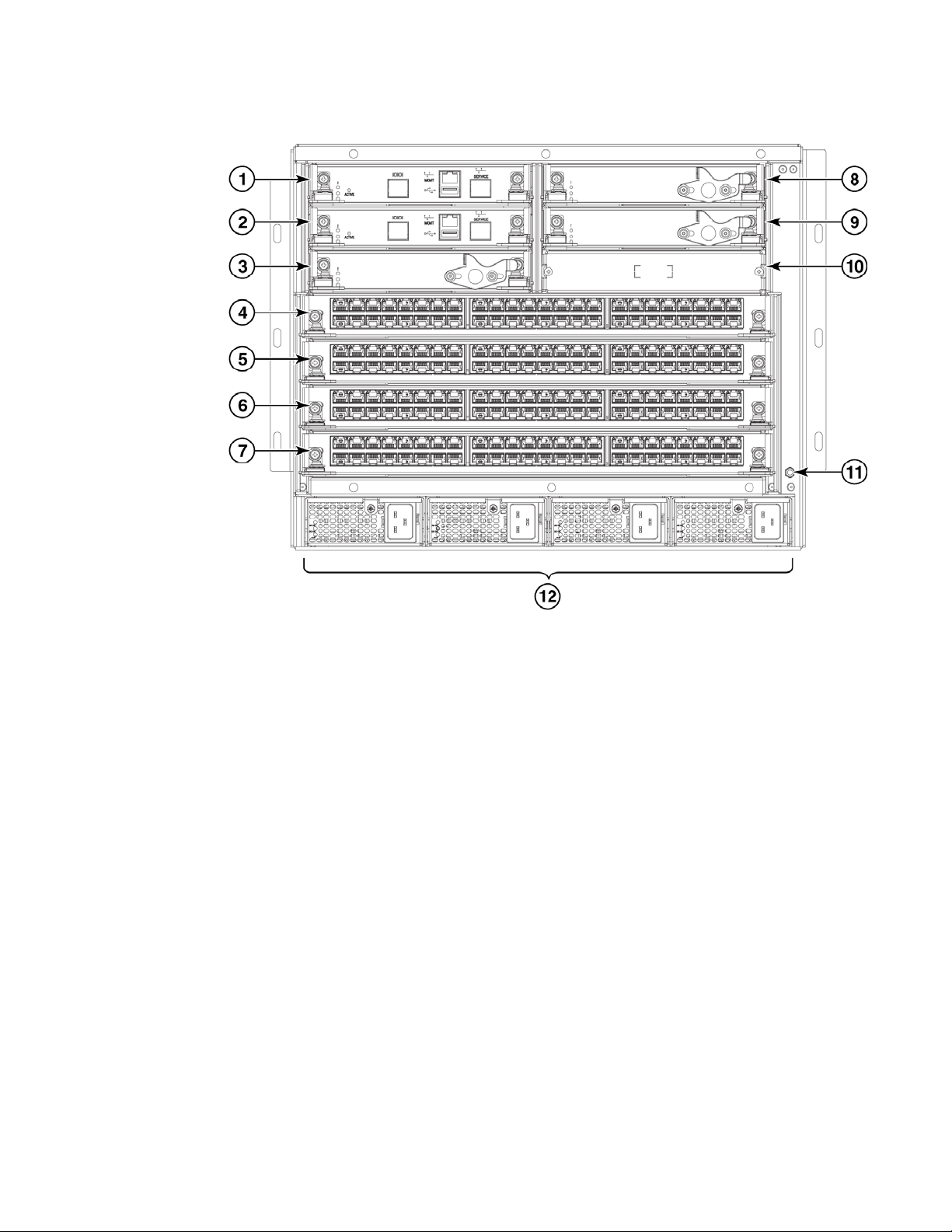
Figure 1 displays a sample configuration of the port side of the Brocade VDX 8770-4.
Brocade VDX 8770-4 Hardware Reference Manual 3
53-1002563-04
Page 24
Brocade VDX 8770-4 hardware components
1
1 Management module slot 1 7 Line card slot 4
2 Management module slot 2 8 Switch fabric module slot 2
3 Switch fabric module slot 1 9 Switch fabric module slot 3
4 Line card slot 1 10 Blank slot - unused
5 Line card slot 2 11 ESD jack
6 Line card slot 3 12 Power supplies (1-4, left to right)
FIGURE 1 Port side of the Brocade VDX 8770-4 (sample configuration)
4 Brocade VDX 8770-4 Hardware Reference Manual
53-1002563-04
Page 25
Brocade VDX 8770-4 hardware components
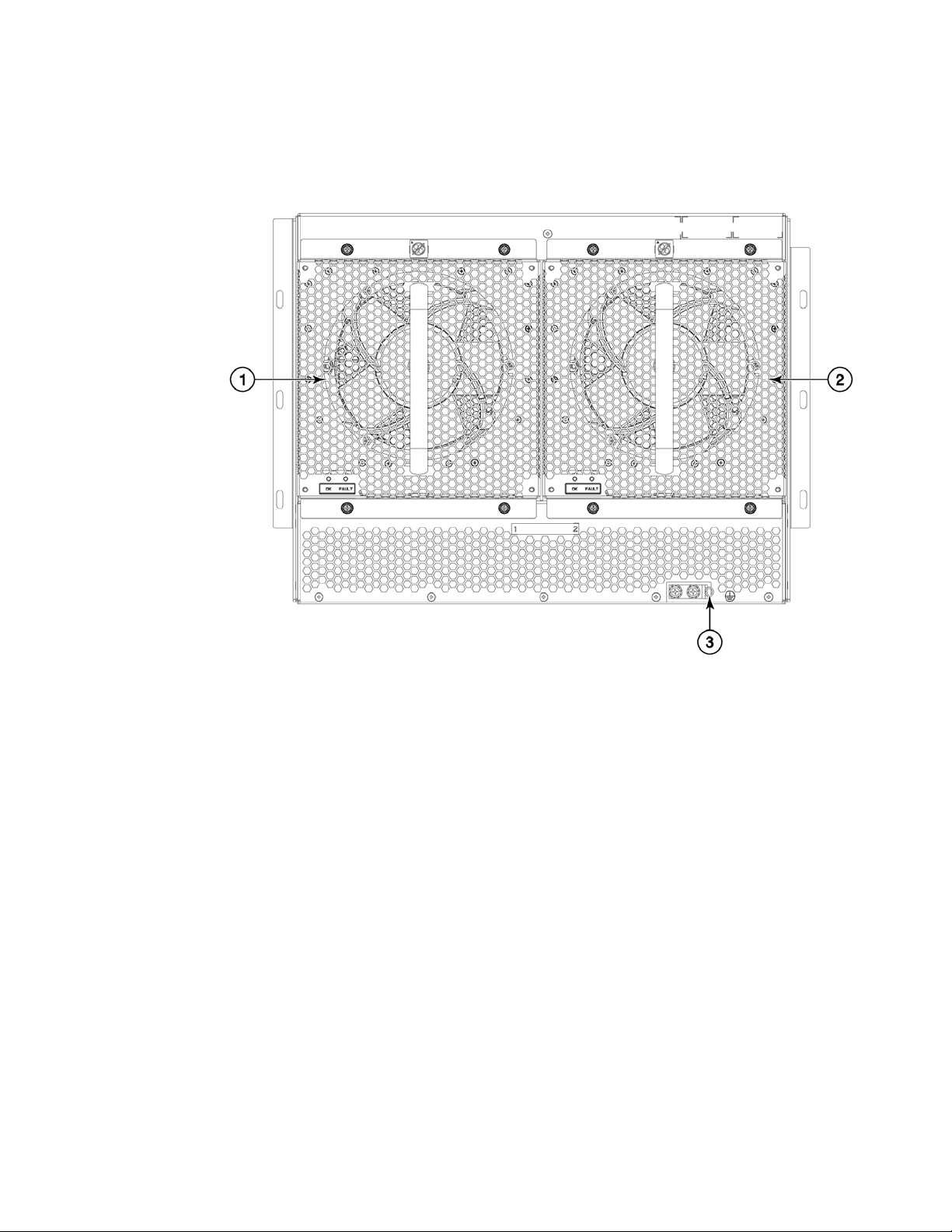
Nonport side of the Brocade VDX 8770-4
Figure 2 displays a sample configuration of the nonport side view of the Brocade VDX 8770-4.
1
1Fan #1 3Ground lug
2Fan #2
FIGURE 2 Nonport side of the Brocade VDX 8770-4 (sample configuration)
Brocade VDX 8770-4 Hardware Reference Manual 5
53-1002563-04
Page 26

Brocade VDX 8770-4 line cards
NOTE
1
Brocade VDX 8770-4 line cards
This section provides general information on the line cards. For specific information on line card
ports and port hardware, refer to Chapter 1, “Brocade VDX 8770-4 Overview”. Table 1 summarizes
the line cards that are available for the Brocade VDX 8770-4.
TABLE 1 Line cards available for the Brocade VDX 8770-4
Line card Description
12x40 GbE 12 40 Gbps QSFP Ethernet ports.
48x10 GbE 48 1/10 Gbps Ethernet ports.
48x1 GbE 48 1 Gbps Ethernet ports.
6x100 GbE 6 100 Gbps Ethernet ports
48x10G-T 48 1/10 Gbps Base-T Ethernet ports
27x40 GbE 27 40 Gbps QSFP Ethernet ports
Breakout mode
Quad SFP (QSFP) 40 Gbps ports on 12x40 GbE and 27x40 GbE line cards can be configured in
breakout mode to create four separate 10 Gbps interfaces. You can administer and operate these
interfaces as any other SFP port. Special breakout cables provide a connection to the 40 Gbps
QSFP port and to four 10 Gbps SFP ports on another switch. Twinax active copper cables at 1, 3,
and 5 meters and fiber-optic breakout cables are supported.
While 40 GbE ports are in breakout mode, port status (individual or as a group) cannot be
determined from the port LED state color.
For more information on configuring breakout mode, refer to the Network OS Administrator’s
Guide.
Trunking
Network OS supports Brocade trunks (hardware-based link aggregation groups, or LAGs). These
trunks are dynamically formed between two adjacent switches with connected interswitch link (ISL)
ports unless trunking is disabled on connecting ports. Traffic is evenly distributed along all links in
a trunk. For more information on Brocade Trunking and enabling and disabling trunking, refer to the
“Configuring Brocade VCS Fabrics” chapter in the Network OS Administrator’s Guide.
Trunking is supported on GbE interface ports of all line cards
Port groups
Port groups are established for trunking on supported line cards. To successfully form a trunk from
line card ports to another switch, select ports from same line card port group and configure each
port to operate at the same speed. Following are trunk and port group specifications for supported
line cards:
6 Brocade VDX 8770-4 Hardware Reference Manual
53-1002563-04
Page 27

Brocade VDX 8770-4 line cards
NOTE
1
• For the 48x10 GbE line card, up to 8 ports are allowed per trunk. Select ports from octet port
groups consisting of ports 1-8, 9-16, 17-24, 25-32, 33-40, and 41-48.
• For the 48x10G-T line card, up to 16 ports are allowed per trunk. Select ports from three port
groups consisting of ports 1-16, 17-32, and 33-48.
• For the 12x40 GbE line card, up to two 40GbE ports are allowed per trunk when these ports
are configured in breakout mode to provide 10GbE interfaces. Select ports from six port
groups consisting of 40GbE ports 1-2, 3-4, 5-6, and 7-8, 9-10, and 11-12.
• For the 27x40 GbE line card, 40GbE ports must be configured in breakout mode to provide
10GbE interfaces for trunking. There are nine port groups consisting of 40GbE ports 1-3, 4-6,
7-9, 10-12, 13-15, 16-18, 19-21, 22-24, and 25-27. The following rules apply to configuring
breakout mode and trunking on ports in these groups:
- You must configure a port group in Performance operating mode. Breakout mode is not
supported on ports configured in Density (default) operating mode.
- When the port group is in Performance mode, you can only configure the first two ports in
the port group in breakout mode, since the third port in the group is disabled. Hence,
trunking is only supported on the first two ports in the port group.
For more information on Performance and Density operating modes, refer to “Configuring
operating modes on 27x40 GbE line cards” on page 35.
27x40 GbE operating modes
The 27x40 GbE line card supports nine port groups of three ports each that you can configure for
Performance or Density operating modes.
• Performance mode - Because the line card is oversubscribed and cannot support the 40 Gbps
line rate on all 27 ports, you can configure Performance mode to achieve 40 Gbps rate for up
to 18 ports. When a port group is configured In Performance mode, the third port in the port
group is persistently disabled, but the remaining two ports operate at up to 40 Gbps to achieve
the 80 Gbps maximum rate for the port group. QSFP breakout mode is only supported on ports
configured in Performance mode.
• Density mode - This is the default mode for all the port groups. In this mode, all the three
ports are enabled in each group, but cannot support the 40 Gbps maximum rate. If this
mode is configured on all port groups, 27 total ports are available for use.
Configure Performance or Density mode for individual port groups using Network OS commands
(refer to the Network OS Command Reference).
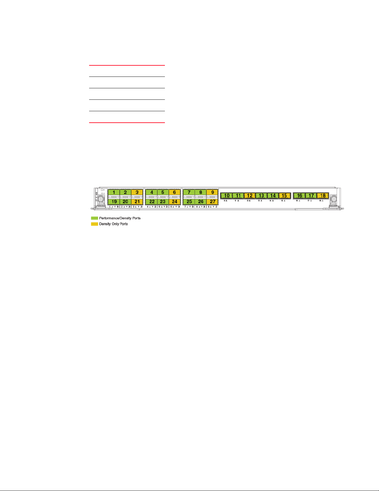
For configuring operation modes, ID numbers are assigned to each port group sequentially from
port 1 through 27 as shown in the Tab le 2 and Figure 3.
TABLE 2 27x40 GbE line card port groups
Port Group ID Port Numbers
11-3
24-6
37-9
4 10-12
Brocade VDX 8770-4 Hardware Reference Manual 7
53-1002563-04
Page 28
High availability
.
1
TABLE 2 27x40 GbE line card port groups
513-15
616-18
719-21
8 22-24
9 25-27
Port groups for configuring operation modes are illustrated in Figure 3. If you configure a port group
in Performance mode, the first two ports in a group are enabled for Performance mode. The third
port is disabled as it can only be configured in density mode only. If you configure the port group in
Density mode, all three ports are enabled for density mode. To identify the port group, use the
format rbridge-id/slot-id/port group-id. For example, 1/3/9 denotes RBridge 1, slot 3, and
port-group-id 9.
FIGURE 3 Port groups for configuring Performance and Density modes on 27x40 GbE line card
To configure Performance and Density modes for line card port groups using Network OS
commands, refer to “Configuring operating modes on 27x40 GbE line cards” on page 35.
High availability
High availability is currently limited to management module configuration synchronization. Failover
to the standby module will occur in case of active module failure, but the standby module will go
through a cold recovery in which all system components are reset. This will disrupt traffic on the
chassis. The reset could take up to eight minutes depending on chassis configuration and traffic
load.
The Brocade VDX 8770-4 provides the following features to enhance and ensure serviceability:
• Modular design with hot-swappable components.
• Flash memory that stores two firmware images per control processor.
• USB port on management module for most tasks that formerly required an FTP/SCP server,
including software and firmware upgrades.
• Nonvolatile random-access memory (NVRAM), containing the OEM serial number, Brocade
serial number, revision information, and part number information.
• Background health-check daemon.
• Memory scrubber, self test, and bus ping to determine if a bus is not functioning.
• RASlog messages.
• SMI-S compliant.
8 Brocade VDX 8770-4 Hardware Reference Manual
53-1002563-04
Page 29

• Hardware and software watchdog timers.
• Status LEDs.
• Predictive diagnostics analysis through Fabric Watch.
• SNMP (including version 3) integration with higher-layer managers.
• Cable management using vertical finger assemblies to accommodate the horizontal
orientation of the blades.
Software features
The following is a partial list of the features supported in the software. Refer to the Brocade
Network OS Administrator’s Guide for details on software and supported features.
Layer 2
• Layer 2 data forwarding
• MAC learning and aging
• Brocade Trunking
• Priority Flow Control (PFC)
• Enhanced Transmission Selection (ETS)
• Terminal Access Controller Access-Control System Plus (TACACS+)
• Link Aggregation Control Protocol (LACP)
• Link Layer Discovery Protocol/ Data Center Bridging eXchange (LLDP/DCBX)
• 802.1x
• Brocade Link Discovery Protocol (BLDP)
Software features
1
Layer 3
• Open Shortest Path First (OSPF) v2
• Static routes
• Virtual Router Redundancy Protocol (VRRP and VRRP-E)
• Internet Group Management Protocol (IGMP) v1 and v2 and snooping
• Address Resolution Protocol (ARP)
Virtualization
• Automatic Migration of Port Profiles (AMPP)
• Support for VLAN, QoS, security, and FCoE port profiles
• VMware vCenter and Brocade Network OS integration
Brocade VDX 8770-4 Hardware Reference Manual 9
53-1002563-04
Page 30

Software features
1
FCoE
• Pause Frames (Tx and Rx)
• Priority Flow Control (PFC)
• Enhanced Transmission Selection (ETS)
• End-to-end, multi-hop FCoE (with proper licensing)
• FCoE and FC zoning and RSCN suppression (name server-based zoning)
• FIP version 1
• FC Fabric Services for FCoE VN-port devices
• Multipath support for FCoE traffic
• FCoE over standard LAGs
• Soft zoning support
Link aggregation
• 802.3ad LACP support
• Virtual Link Aggregation Group (vLAG). A VLAG is a LAG that spans multiple physical switches.
QoS
• 802.1p marking
• Scheduling: Strict priority (SP), Shaped Deficit Weighted Round-Robin (SDWRR)
• CEE provisioning and classification
• Rewrite/marking, queuing
• Congestion control
• Multicast rate limit scheduling
• Port-based SPAN
• Layer 2 and Layer 3 ACLs (ingress and egress)
• Port-based sFLOW
Management
• IPv4 or IPv6 management
• CLI management utilities
• sFlow
• TRILL Operations, Administration, and Management (OAM)
• Distributed configuration management (DCMd)
Licensing
• FCoE licensing: enables FCoE feature set
• Layer 3 licensing: enables IPv4 protocols, such as OSPF, VRRP, and VRRP-E
10 Brocade VDX 8770-4 Hardware Reference Manual
53-1002563-04
Page 31

Software features
1
Brocade VDX 8770-4 Hardware Reference Manual 11
53-1002563-04
Page 32

Software features
1
12 Brocade VDX 8770-4 Hardware Reference Manual
53-1002563-04
Page 33

Chapter
DANGER
Installation of the Brocade VDX 8770-4
In this chapter
•Time and items required. . . . . . . . . . . . . . . . . . . . . . . . . . . . . . . . . . . . . . . . . 13
•Items included with the Brocade VDX 8770-4. . . . . . . . . . . . . . . . . . . . . . . . 15
•Preparing for the Brocade VDX 8770-4 installation . . . . . . . . . . . . . . . . . . . 16
•Unpacking and installing the Brocade VDX 8770-4 . . . . . . . . . . . . . . . . . . . 20
•Port numbering . . . . . . . . . . . . . . . . . . . . . . . . . . . . . . . . . . . . . . . . . . . . . . . . 21
•Providing power to the Brocade VDX 8770-4. . . . . . . . . . . . . . . . . . . . . . . . . 22
Time and items required
You can set up and install the Brocade VDX 8770-4 in the following ways:
• As a standalone unit on a flat surface
• In a four-post rack using the VDX 8770-4 Four-Post Flush and Recessed Mount Intake Air Duct
Rack Kit. This kit is required for the 48x10G-T, 6x100 GbE, and 27x40 GbE and later line cards.
• In a four-post rack
• In a two-post telecommunications (Telco) rack
2
This chapter describes how to set up the Brocade VDX 8770-4 as a standalone unit. For rack mount
installation instructions, refer to the manual that comes with the separately ordered rack kit.
Tab le 3 describes the main installation and setup tasks, the estimated time required for each, and
the items required to complete the task based on a fully populated Brocade VDX 8770-4 (192 10
GbE ports). Configurations with fewer ports require less time. These time estimates assume a
prepared installation site and appropriate power and network connectivity.
Installation and removal of the unit must be carried out by qualified personnel only.
Brocade VDX 8770-4 Hardware Reference Manual 13
53-1002563-04
Page 34

Time and items required
CAUTION
2
TABLE 3 Installation tasks, time, and items required
Installation task Time estimate Items required
Site preparation and unpacking Brocade
VDX 8770-4
Installing the rack mount kit or the VDX
8770-4 Four-Post Flush and Recessed
Mount Intake Air Duct Rack Kit
Mounting and securing Brocade VDX
8770-4 in the rack
Inserting modules and power supplies 5-10 minutes per
Installing power cables and powering on
the Brocade VDX 8770-4
Establishing a serial connection, logging on
to the Brocade VDX 8770-4, and
configuring the IP addresses
Installing an Ethernet cable, opening a
Telnet session, and configuring the
Brocade VDX 8770-4 date and time and
additional system parameters. Verify and
back up configuration.
Installing transceivers as needed 30-60 minutes (up
Attaching cables, cable ties, and cable
guides
30 minutes #2 Phillips screwdriver.
30 minutes
30 minutes
unit
20 minutes Power cables (provided in the Brocade VDX
20 minutes Serial cable (also called the console cable -
20 minutes Ethernet cabling (optional) for Telnet access.
to 30 seconds per
transceiver)
2-3 hours Cables, cable ties, and cable management
Pallet jack.
Hydraulic lift or assisted lift, able to raise to a
minimum of 140 cm (55 in.), with a minimum
capacity of 113 kg (250 lb). A fully loaded
version of the Brocade VDX 8770-4 weighs
86.18 kg (190 lbs).
Refer to the proper rack mount kit instructions
for your specific rack.
Management modules, switch fabric modules,
line cards, power supplies (AC or DC).
8770-4 accessory kit).
provided in the accessory kit).
Workstation computer with a serial (console)
port or terminal server port and a terminal
emulator application (such as HyperTerminal).
Ethernet IP addresses for the Brocade VDX
8770-4 switch and for management modules:
total two or three addresses, depending on the
number of management modules installed.
Refer to the Network OS Administrator’s Guide.
Copper and optical transceivers and
direct-attach cables as needed.
finger assemblies.
The Brocade VDX 8770-4 with DC power sources are intended for installation in restricted access
areas only. A restricted access area is a location where access can be gained only by service
personnel through the use of a special tool, lock and key, or other means of security, and is
controlled by the authority responsible for the location.
14 Brocade VDX 8770-4 Hardware Reference Manual
53-1002563-04
Page 35

Items included with the Brocade VDX 8770-4
NOTE
Items included with the Brocade VDX 8770-4
The basic Brocade VDX 8770-4 (SKUs BR-VDX8770-4-BND-AC or BR-VDX8770-4-BND-DC
depending on whether you order AC or DC power supplies) ships with the following items:
• Brocade VDX 8770-4 chassis, populated with:
- Management modules (one)
- Switch fabric modules (three)
- Filler panels for unoccupied slots for all modules
- Power supplies (up to two)
- Power supply filler panels for unoccupied bays
- Fan modules (two)
• Accessory kit containing the following items:
- Console cable (RJ-45 serial cable: There is also an adapter that can be used to provide a
DB9-style connector.)
- Wrist strap (ESD grounding strap)
- Ground lug kit
- SFP extraction tool kit
- China RoHS guide
- Cable management finger assemblies
- Brocade-branded USB device
- Power cord retainer kit
- Hardware for securing the switch in a rack
- Web pointer document
- Air filter
• Line cards (up to four) and additional power supplies must be ordered separately.
2
The rack mount kits must be ordered separately.
Brocade-branded transceivers (SFP, SFP+, CFP2, QSFP, or 10Base-T) and cables or direct-attach
cables must also be ordered separately. The Brocade VDX 8770-4 supports SR and LR SFP, SFP+,
and CFP2 transceivers. QSFP transceivers are SR transceivers only. Twinax active copper and fiberoptic breakout cables are supported.
For information about the transceivers that are qualified for the Brocade VDX 8770-4, refer to
http://www.brocade.com/downloads/documents/matrices/Brocade_Compatibility_Matrix.pdf.
Brocade VDX 8770-4 Hardware Reference Manual 15
53-1002563-04
Page 36

Preparing for the Brocade VDX 8770-4 installation
NOTE
DANGER
NOTE
CAUTION
2
Preparing for the Brocade VDX 8770-4 installation
Refer to the safety notices before installation (refer to “Safety notices”).
Refer to “NEBS requirements” to ensure compliance with NEBS-GR-1089 standards.
Refer to “Power specifications” to plan for meeting power supply standards before installing the
chassis.
Refer to “Environmental requirements” to plan for your environmental needs.
Refer to “Managing cables” to plan for cable management.
Installation and removal of the unit must be carried out by qualified personnel only.
The following steps are required to ensure correct installation and operation.
Brocade strongly recommends that devices be installed in environments that have minimal dust and
airborne contaminants.
1. Ensure that doorways are wider than 91 cm (36 in.) to accommodate the switch.
2. Provide a space that is 8 rack units (8U) high, 61.19 cm (24.09 in.) deep, and 43.74 cm (17.22
in.) wide. One rack unit is equal to 4.45 cm (1.75 in.). If you are using the VDX 8770-4
Four-Post Flush and Recessed Mount Intake Air Duct Rack Kit, you will need a space that is
10U high to accommodate both the Intake Air Duct Rack Kit and the switch.
Plan to install the Brocade VDX 8770-4 with the port side facing the air-intake aisle. Airflow is
from the left side of the switch to the fan side. If you are using the Intake Air Duct Rack Kit for
mounting the Brocade VDX 8770-4, then the airflow is from the port side to the fan side.
Ensure that the rack is balanced and mechanically secured to provide stability in the event of
an earthquake and that the equipment does not exceed the rack’s weight limits.
3. Ensure that dedicated electrical branch circuits with the following characteristics are available:
• Up to four dedicated fused 200–240 VAC, 50–60 Hz feeds or -48 VDC (one per power
supply)
• One cable for each power supply
Use a separate branch circuit for each AC power cord, which provides redundancy in case one of
the circuits fails.
• Protected by a circuit breaker in accordance with local electrical codes
• Supply circuit, line fusing, and wire size adequate to the electrical rating on the switch
nameplate
• Location close to the switch and easily accessible
16 Brocade VDX 8770-4 Hardware Reference Manual
53-1002563-04
Page 37

Preparing for the Brocade VDX 8770-4 installation
DANGER
• Grounded outlets installed by a licensed electrician and compatible with the power cords
If the installation requires a different power cord than the one supplied with the device, make
sure you use a power cord displaying the mark of the safety agency that defines the regulations
for power cords in your country. The mark is your assurance that the power cord can be used
safely with the switch.
4. Plan for cable management before installing the switch.
Cables can be managed in a variety of ways, such as by routing cables below the switch, to
either side of the switch, through cable channels on the sides of the rack, or by using patch
panels.
5. Ensure that the following items are available for configuration of the Brocade VDX 8770-4:
• Workstation with an installed terminal emulator, such as HyperTerminal
• Console (serial) cable (provided)
• Ethernet cables (not provided)
• Either access to an FTP server or a Brocade USB device for backing up the switch
configuration or collecting supportsave output data (optional)
• Transceivers (copper and optical) and compatible cables and direct-attach cables if
needed
2
6. Ensure that the air intake and exhaust vents have a minimum of 5.1 cm (2 in.) of airspace.
7. Ensure that the air temperature on the air intake side is less than 40°C (104°F) during
operation.
Power specifications
Power for the Brocade VDX 8770-4 can be supplied with either AC- or DC-based 3000 watt power
supplies. The Brocade VDX 8770-4 has room for up to four power supplies.
Tab le 4 shows the basic power specifications for each power supply.
.
TABLE 4 Power specifications
Specification Value for 3000W AC power supply Value for 3000W DC power supply
Input rating 16A 70A
Input voltage 200–240 VAC, 50-60 Hz, 16.0 Amp
maximum
Operating range 180 ot 264 VAC -40 to -60 VDC
Inrush current Limited to 60 Amp peak for any initial
current surge or spike of 10 ms or less at
either cold or warm start. Any additional
inrush current surges or spikes in the form
of AC cycles or multiple AC cycles greater
than 10 ms and less than 150 ms, must not
exceed 25 Amp peak.
Output 12 VDC, 245 Amps 12 VDC, 245 Amps
-48 VDC
Limited to 70 Amp peak for any initial
current surge or spike of 10 ms or less at
either cold or warm start.
Brocade VDX 8770-4 Hardware Reference Manual 17
53-1002563-04
Page 38

Preparing for the Brocade VDX 8770-4 installation
CAUTION
CAUTION
2
For the DC input circuit to the system of a Brocade VDX 8770-4 (3000W supply), make sure there
is an 80 Amp circuit breaker, minimum -48VDC, double pole, on the input lugs to the power
supply. The input wiring for connection to the product should be copper wire, 2 AWG, marked
VW-1, and rated minimum 90oC.
The power requirements for a given switch configuration depend on which modules have been
installed in the switch. Tabl e 5 shows the power consumption for the modules that can be used in
the Brocade VDX 8770-4 switch along with the power consumption for the cooling fans.
All numbers for the line cards assume that the card is fully populated with transceivers, including
QSFPs for the 12x40 GbE and 27x40 GbE line cards. All ports are Ethernet.
You can calculate your power requirements by combining the power demands for the various
modules and fan units in your configuration. While you may use fewer ports in a given line card, it is
always safer to use the power requirement of a fully populated card.
TABLE 5 Power demands per component
Module or fan units Power demand at idle -
blades enabled, no
optics, ports disabled
(Watts)
Nominal power demand blades enabled, optics, 50%
line rate, random packets
(Watts)
Maximum power demand - blades
enabled, optics, traffic present, full line
rate, 64 byte smallest packet, 40°C
ambient temp., maximum power for all
supported optics (Watts)
Management module 46 46 50
Switch fabric module 120 120 132
48x1 Gbe line card 245 310 460
48x10 GbE line card 245 310 460
12x40 GbE line card 247 290 440
48x10G-T line card 450 665 700
27x40 GbE line card 429 489 580
6x100 GbE line card 570 611 700
Fan unit 25 25 268
For the NEBS-compliant installation of a Brocade VDX 8770-4 with AC or DC systems, use a
ground wire of at least 2 AWG. The ground wire should have an agency-approved crimped
connector (provided with the device) attached to one end, with the other end attached to building
ground. The connector must be crimped with the proper tool, allowing it to be connected to both
ground screws on the enclosure. Before crimping the ground wire into the provided ground lug,
ensure that the bare copper wire has been cleaned and antioxidant is applied to the bare wire. In
addition, anti-rotation devices or lock washers must be used with all screw connections for the
grounding wire.
18 Brocade VDX 8770-4 Hardware Reference Manual
53-1002563-04
Page 39

Preparing for the Brocade VDX 8770-4 installation
DANGER
NOTE
2
Environmental requirements
Do not install the device in an environment where the operating ambient temperature might
exceed 40°C (104°F).
Tab le 6 lists the environmental operating ranges for the Brocade VDX 8770-4. The requirements for
non-operating conditions are also provided for acceptable storage and transportation
environments.
TABLE 6 Environmental requirements
Condition Acceptable range during operation Acceptable range during non-operation
Ambient temperature 0 to 40 C (32 to 104 F) outside
switch
Humidity 5% to 90% RH noncondensing, at 40 C
(104
F), with maximum gradient of 10%
per hour
Altitude 0 to 3 km (10,000 ft.) above sea level 0 to 12 km (40,000 ft.) above sea level
Shock 20G, 6 ms duration, half-sine wave 33G, 11 ms duration, half-sine wave
Vibration 0.5G p-p, 5-500 Hz at 1.0 octave/minute 2.0G p-p, 5-500 Hz at 1.0 octave/minute
Airflow Maximum: 675 cu ft/min. (1147 cu m/hr)
Nominal: 200 cu ft/min. (340 cu m/hr)
Maximum heat
dissipation
Up to 6000W or 20,500 BTU/hr Not applicable
-25 to +70 C (-13 to 158 F) outside
switch
10% to 90% RH noncondensing, at 70
(158
F)
None required
C
The 0 to 40C (32 to 104F) range applies to the ambient air temperature at the air intake vents
on the left side (as you face the port side) and port side of the Brocade VDX 8770-4.
The temperature inside the Brocade VDX 8770-4 can be up to 90°C (194
during operation. Brocade recommends that the internal temperature not exceed 75°C (167
F) for some modules
F).
Cooling policy is based on a combination of ambient temperature and measured temperature on the
modules. Various combinations will result in an increase in fan speed to create more cooling in the
switch.
If a component approaches a critical temperature that will trigger a module shutdown, there will be
a WARNING message in the RASlog, followed by a CRITICAL message saying that the module will
shut down in two minutes.
Use the show environment command to view temperature status.
Brocade VDX 8770-4 Hardware Reference Manual 19
53-1002563-04
Page 40

Unpacking and installing the Brocade VDX 8770-4
NOTE
NOTE
2
Chassis slots
Switch slots are coded and numbered to differentiate between management module slots, switch
fabric module slots, and line card slots. Management modules (MMs) must be installed only in
slots M1 and M2. Switch fabric modules (SFMs) must be installed only in slots S1 through S3.
There must be at least one SFM installed in either slot S1 or slot S2. The line card slots, L1 through
L4, can be filled with any supported line cards. Unused slots must be filled with the correct filler
panels to maintain adequate cooling.
Unpacking and installing the Brocade VDX 8770-4
Use the following procedure to unpack and install your Brocade VDX 8770-4.
A fully populated Brocade VDX 8770-4 weighs approximately 86.18 kg (190 lb) and requires a
hydraulic or assisted lift to install it. Use safe lifting practices when moving this product.
1. Unpack the Brocade VDX 8770-4.
a. Cut the bands that encircle the packaging.
b. Slide the upper portion of the cardboard shipping box up off the pallet and shipping tray.
The Brocade VDX 8770-4 packaging incorporates a wood pallet and brackets. The switch sits
on top of a corrugated cardboard shipping tray.
c. Save the packing materials for use when returning a switch.
d. Leave the switch on top of the shipping tray and pallet if the switch must be transported to
the installation location.
2. Use a pallet jack or other assisted lift to transport the new switch to the installation area.
3. Using the rack mount instructions, install the rack components in the rack and mounting
flanges on the switch. The rack mount kit and instructions are shipped separately from the
switch.
4. Remove the accessory kit (cardboard box), packing foam, and anti-static plastic from the
switch and set them aside.
5. Remove the foam inserts around the base of the switch.
6. Use a lift to raise the switch to the correct level. If installing the switch in a rack, follow the
instructions provided by the rack kit manufacturer.
7. If applicable, lock the wheels of the lift.
8. Ensure that the switch is oriented so that the left side and port side (front) have access to
intake air.
9. Gently slide the switch onto the final installation surface, ensuring that it remains supported
during the transfer.
10. Before you apply power to the switch, you can install the MM, SFM, and line card modules as
well as power supplies to speed up your installation.
20 Brocade VDX 8770-4 Hardware Reference Manual
53-1002563-04
Page 41

Port numbering
The Brocade VDX 8770-4 uses the following port numbering method:
• 12x40 GbE line card modules — Ports are numbered from 1 through 12 from left to right when
FIGURE 4 12x40 GbE line card
• 48x1 GbE and 48x10 GbE line card modules — Ports are numbered from 1 through 48, from
Port numbering
installed in the switch. Refer to Figure 4.
left to right, with the odd-numbered ports on the upper row and the even-numbered ports on
the lower row when installed in the switch. Refer to Figure 5.
2
FIGURE 5 48x10 GbE line card (48x1 GbE line card is similar)
• 48x10G-T line card modules — Ports are numbered from 1 through 48, from left to right, with
the odd-numbered ports on the upper row and the even-numbered ports on the lower row
when installed in the switch. Refer to Figure 6.
FIGURE 6 48x10G-T line card
• 27x40 GbE line card modules — In the dual-port section, the top row of ports is numbered from
1 through 9 and the lower row of ports is numbered 19 through 27 from left to right when
installed on the switch. The single ports on the right of the switch are numbered 10 through 18
from left to right. Refer to Figure 7.
FIGURE 7 27x40 GbE line card
• 6x100 GbE line card modules — Ports are numbered from 1 through 6, from left to right when
installed in the switch. Refer to Figure 8.
Brocade VDX 8770-4 Hardware Reference Manual 21
53-1002563-04
Page 42

Providing power to the Brocade VDX 8770-4
NOTE
2
FIGURE 8 6x100 GbE line card
Providing power to the Brocade VDX 8770-4
Complete the following steps to provide power to the chassis. Each power supply has one power
cord.
Use the supplied power cords. Ensure the facility power receptacle is the correct type, supplies the
required voltage, and is properly grounded.
Connecting an AC power cord
1. Plug the power cord into the power supply.
2. Route the cable so it will be out of the way when connected to the power source.
3. Plug the other end of the cable into the power source.
Connecting a DC power cord
1. Use a #1 Phillips screwdriver to remove the screw that secures the safety cover over the power
lugs and remove the safety cover.
2. Use a #2 Phillips screwdriver to unscrew the power lugs.
3. Obtain heat shrink tubing with the following specifications to install on the #2 AWG power
supply input wire:
• Inside diameter: 1.27 cm (.5 in.)
• Minimum 2:1/50% shrink ratio
• Nominal Rec. Wall Thickness: 30480 mm (.012 in.) minimum
• Dielectric strength: 800V/mil
• Tensile strength: greater than or equal to 5000 psi
• Operating temperature: -40°C to +150°C (-40°F to 302°F) minimum
• RoHS compliant
4. Cut off a 5.08 cm (2 in) lengths for each #2 AWG power supply wire.
5. Slide the tubing over the #2 AWG power supply wire.
6. Crimp the #2 AWG power supply wire into the power lug.
7. Slide the tubing over the lug to the brown strip closest to the lug holes.
8. Apply heat to shrink the tubing over the lug and wire insulation.
22 Brocade VDX 8770-4 Hardware Reference Manual
53-1002563-04
Page 43

Providing power to the Brocade VDX 8770-4
NOTE
ATTENTION
Installed tubing and lugs on power supply wire should conform to Figure 9.
1Heatshrink tubing 2Power lug
FIGURE 9 Heat shrink tubing and lug on DC power supply cable
9. Connect the power lugs to the power supply unit.
Connect the -48V wire to the negative terminal and the 0V wire to the positive terminal.
The DC return must be isolated from the chassis ground (DC-I) when making connections to
the power supply.
2
10. Replace the safety cover.
11. Plug the other end of the cable into the power source.
Do not connect the switch to the network until the IP addresses are configured.
For information about LED patterns, refer to Chapter 4, “Monitoring System Components”.
Brocade VDX 8770-4 Hardware Reference Manual 23
53-1002563-04
Page 44

Providing power to the Brocade VDX 8770-4
2
24 Brocade VDX 8770-4 Hardware Reference Manual
53-1002563-04
Page 45

Chapter
Configuring the Brocade VDX 8770-4
In this chapter
•Preparing to configure the Brocade VDX 8770-4 . . . . . . . . . . . . . . . . . . . . . 25
•Establishing a serial connection to the Brocade VDX 8770-4 . . . . . . . . . . . 26
•Logging in to the serial console port . . . . . . . . . . . . . . . . . . . . . . . . . . . . . . . 28
•Changing the RBridge ID. . . . . . . . . . . . . . . . . . . . . . . . . . . . . . . . . . . . . . . . . 28
•Assigning permanent passwords . . . . . . . . . . . . . . . . . . . . . . . . . . . . . . . . . . 29
•Configuring the IP addresses . . . . . . . . . . . . . . . . . . . . . . . . . . . . . . . . . . . . . 29
•Logging off the serial console port and disconnecting the serial cable . . . 31
•Establishing an Ethernet connection to the Brocade VDX 8770-4 . . . . . . . 31
•Customizing a host name . . . . . . . . . . . . . . . . . . . . . . . . . . . . . . . . . . . . . . . . 31
•Customizing a chassis name . . . . . . . . . . . . . . . . . . . . . . . . . . . . . . . . . . . . . 32
•Setting the date and time . . . . . . . . . . . . . . . . . . . . . . . . . . . . . . . . . . . . . . . . 32
•Determining installed software licenses . . . . . . . . . . . . . . . . . . . . . . . . . . . . 35
•Configuring operating modes on 27x40 GbE line cards. . . . . . . . . . . . . . . . 35
•Saving your changes . . . . . . . . . . . . . . . . . . . . . . . . . . . . . . . . . . . . . . . . . . . . 36
•Verifying correct operation . . . . . . . . . . . . . . . . . . . . . . . . . . . . . . . . . . . . . . . 37
•Backing up the configuration . . . . . . . . . . . . . . . . . . . . . . . . . . . . . . . . . . . . . 37
•Connecting network devices. . . . . . . . . . . . . . . . . . . . . . . . . . . . . . . . . . . . . . 38
•Installing transceivers and attaching cables . . . . . . . . . . . . . . . . . . . . . . . . . 39
•Managing cables . . . . . . . . . . . . . . . . . . . . . . . . . . . . . . . . . . . . . . . . . . . . . . . 40
3
Preparing to configure the Brocade VDX 8770-4
The Brocade VDX 8770-4 must be configured before it is connected to the fabric, and all of the
configuration commands must be entered through the active MM. The Brocade VDX 8770-4
configuration includes the following parameters:
• RBridge ID, if you are going to have more than one switch in a fabric.
• IP address and gateway address for the switch
• IP addresses, host names, and gateway addresses for one or two MMs, as needed
• Host name
You also need to change passwords from their default values and set the time and date, either by
the way of NTP or manually.
Brocade VDX 8770-4 Hardware Reference Manual 25
53-1002563-04
Page 46

Establishing a serial connection to the Brocade VDX 8770-4
NOTE
3
The configuration information is mirrored to the standby MM, if you have installed one, which
allows the current configuration to remain available even if the active MM fails. The configuration
information for the Brocade VDX 8770-4 is stored in the CID cards and the flash memory of the
MMs. The configuration can be backed up to a workstation (uploaded) and then downloaded to the
active MM if necessary.
The Brocade VDX 8770-4 boots up in VCS™ fabric cluster mode and will attempt to form ISLs with
connected VCS-enabled switches,. If the chassis is not connected to another switch, it forms a
“single node VCS fabric.” This means that the chassis operates as a standalone system, but the
operational mode is always VCS-enabled.The switch does not support standalone mode.
Fabric cluster mode is defined as a fabric in which the data path for nodes is distributed each
member switch in the fabric, but the configuration path is not distributed. Each node keeps its
configuration database independently. Fabric cluster mode has three major characteristics:
• The fabric is self-forming. When two or more VCS-enabled switches with unique RBridge IDs
are connected to form a VCS fabric, the fabric is automatically created and the switches
discover the common fabric configuration.
• The fabric is masterless. No single switch stores configuration information or controls fabric
operations. Any switch can fail or be removed without causing disruptive fabric downtime or
delayed traffic.
• The fabric is aware of all members, devices, and Virtual Machines (VMs). Automatic Migration
of Port Profiles (AMPP) supports VM migration to another physical server. If the VM moves, it is
automatically reconnected to all of its original resources.
When the switch connects with a VCS cluster, negotiation protocols determine which switch in the
fabric is the principal switch an makes sure that all domain IDs, and therefore RBridge IDs, are
unique. Once the domain IDs are determined to be unique, they are equated to the RBridge IDs.
The switch with the lowest World Wide Name (WWN) becomes the principal switch, primarily for
purposes of determining the uniqueness of the ID of the other switches in the fabric. The WWN is a
unique identifier burned into the switch at the factory.
If necessary you can change VCS ID.for the switch using the vcs vcsid vcsid command, where the
vcsid is a value from 1 to 8192. By default, the VCS ID of every Brocade VDX 8770-4 is 1. Change
the VCS ID if you need to create a new, separate VCS fabric.
In order to retain the changes made during configuration, you must copy the running configuration
file to the startup configuration file using the copy running-config startup-config command. This will
ensure that the switch reboots to your preferred configuration.
Establishing a serial connection to the Brocade VDX 8770-4
The serial port is located on the port side of the Brocade VDX 8770-4. The switch uses an RJ-45
connector for the serial port. An RJ-45 to DB9 adapter is also provided with the Brocade VDX
8770-4. The cable supplied with the switch is a rollover cable. The serial port is used to connect
to a workstation to configure the Brocade VDX 8770-4 IP address before connecting the switch to a
fabric or IP network.
To protect the serial port from damage, keep the cover on the port when not in use.
To establish a serial connection to the serial (console) port on the Brocade VDX 8770-4, complete
the following steps.
26 Brocade VDX 8770-4 Hardware Reference Manual
53-1002563-04
Page 47

Establishing a serial connection to the Brocade VDX 8770-4
ATTENTION
3
1. Verify that the Brocade VDX 8770-4 is powered on and that POST is complete by verifying that
all power LED indicators on the management, switch fabric, and line card modules display a
steady green light.
2. Remove the shipping cap from the serial port (labeled I0I0I) on the active MM.
By default, the MM installed in slot M1 is the active MM unless an error occurs. The active MM
is also indicated by an illuminated blue LED labeled ACTIVE.
3. Use the serial cable provided with the Brocade VDX 8770-4 to connect the serial port on the
active MM to a computer workstation.
If the serial port on the workstation or terminal device is DB9 instead of RJ-45, remove the
adapter on the end of the serial cable and insert the exposed DB9 connector into the DB9
serial port on the workstation.
The serial port is intended primarily for the initial setting of the IP address and for service
purposes.
4. Disable any serial communication programs running on the workstation (such as
synchronization programs).
5. Open a terminal emulator application (such as HyperTerminal on a PC, or TERM, TIP, or Kermit
in a UNIX environment), and configure the application as follows:
• In a Windows environment, use the parameters shown in Table 7:
TABLE 7 Windows serial connection parameters
Parameter Value
Bits per second 9600
Data bits 8
Parity None
Stop bits 1
Flow control None
• In a UNIX environment, enter the following string at the prompt:
tip /dev/ttyb -9600
If ttyb is already in use, use ttya instead and enter the following string at the prompt:
tip /dev/ttya -9600
Tab le 8 lists the serial cable pinouts.
TABLE 8 Serial cable pinouts
PIN Signal Description
1Not supported NA
2Not supported NA
3TXD Transmit data
4GND Logic ground
Brocade VDX 8770-4 Hardware Reference Manual 27
53-1002563-04
Page 48

Logging in to the serial console port
3
TABLE 8 Serial cable pinouts
PIN Signal Description
5Not supported NA
6RXD Receive data
7Not supported NA
8Not supported NA
Logging in to the serial console port
Log in to the Brocade VDX 8770-4 through the serial connection with the admin user name. The
default password is password. While you are not required to change the password at the initial
login, Brocade recommends that you change your admin and user passwords. Refer to “Assigning
permanent passwords” for more details. Make sure to write down the new passwords and keep this
information in a secure location.
Network OS (8770HOST)
8770HOST console login: admin
Password:
WARNING: The default password of 'admin' and 'user' accounts have not been
changed.
Welcome to the Brocade Network Operating System Software
admin connected from 127.0.0.1 using console on 8770HOST
8770HOST#
Changing the RBridge ID
If you are going to have more than one switch in a fabric, each switch must have a unique RBridge
ID. The default RBridge ID for any Brocade VDX 8770-4 is 1. Use the vcs rbridge-id [rbridge-id]
command to change the default RBridge ID. You should be in privileged EXEC mode to run the
command. If you have made any other configuration changes you want to persist, be sure to save
your running configuration to the startup configuration before running the vcs rbridge-id command
as this command reboots the switch.
1. Log on to the switch using the admin account (the default password is password).
2. Enter the vcs rbridge-id [rbridge-id] command.
switch# vcs rbridge-id 2
This operation will change the configuration to default and reboot the switch.
Do you want to continue? [y/n]:y
3. Enter y.
The reply to the command will include a line about the setting of the RBridge ID.
Successfully set rbridge-id.
28 Brocade VDX 8770-4 Hardware Reference Manual
53-1002563-04
Page 49

Assigning permanent passwords
NOTE
The factory-configured default accounts on the switch are admin and user. Use the default
administrative account as shown in Table 9 to log in to the switch for the first time and to perform
the basic configuration tasks. The user account is read-only and used primarily for system
monitoring.
TABLE 9 Default administrative account names and passwords
Account type Login name Password
Administrative admin password
User account (read-only) user password
Changing the default account passwords
When you change the default account password after you log in for the first time, only the default
password rule is in effect. The rule specifies a minimum password length of eight characters. For
advanced user and role management, including setting password rules, refer to the Security
chapter of the Network OS Administrator’s Guide.
Assigning permanent passwords
3
Passwords can be 8 to 40 characters long. They must begin with an alphabetic character. They can
include numeric characters, the period (.), and the underscore (_) only. Passwords are
case-sensitive, and they are not displayed when you enter them on the command line. The available
roles are admin and user. For more information on passwords, refer to the Network OS
Administrator’s Guide.
1. Log on to the switch using the admin account (the default password is password).
2. Enter configure terminal to change to global configuration mode.
switch# configure terminal
Entering configuration mode terminal
3. Enter the configure terminal command to enter global configuration mode.
4. Enter the username command followed by the account name and the password parameter.
5. When prompted, enter the new password. and press Enter.
Following is an example of using these commands:
Switch# configure terminal
Entering configuration mode terminal
switch(config)# username admin password [new-password]
(<WORD>;;User password satisfying password-attributes):********
Configuring the IP addresses
You can must configure the Brocade VDX 8770-4 with a static IP address. DHCP is not supported
on the Brocade VDX 8770-4. The Brocade VDX 8770-4 supports both IPv4 and IPv6 format
addresses.
Brocade VDX 8770-4 Hardware Reference Manual 29
53-1002563-04
Page 50

Configuring the IP addresses
ATTENTION
3
Setting a static IP address
Complete the following steps to set a static IP address.
1. Log in to the switch using an account that has the admin role.
2. Enter global configuration mode using the configure terminal command.
3. Specify the chassis with the rbridge-id command.
4. Use the chassis virtual-ip command to set the IP address for the chassis.
5. Return to configuration mode by entering exit.
6. Use the ip address command to set the Ethernet IP address for the MMs.
switch(config)# rbridge-id 1
switch(config-rbridge-id 1)# chassis virtual-ip 10.20.236.132/20
If you are going to use an IPv4 IP address, enter the IP address in dotted decimal notation. You
should also enter a gateway address as well.
When you have assigned the IP and gateway addresses to management interface 1/1, you
should also assign IP and gateway addresses to management interface 1/2 if you have
installed a second MM.
switch(config)# interface Management 1/1
switch(config-Management-1/1)# no ip address dhcp
switch(config-Management-1/1)# ip address 10.24.85.81/20
switch(config-Management-1/1)# ip gateway-address 10.24.80.1
The ip gateway-address command will not be available on the Brocade VDX 8770-4 if the Layer
3 or Advanced license is installed. In that case, use the following command sequence:
switch(config)# rbridge-id 1
switch(config-rbridge-id 1)# ip route 0.0.0.0/0 <default-gateway>
If you are going to use an IPv6 address, enter the network information in semicolon-separated
notation as prompted after the ipv6 address operand. You should also disable DHCP.
switch(config)# interface Management 1/1
switch(config-Management-1/1)# no ip address dhcp
switch(config-Management-1/1)# ipv6 address \
fd00:60:69bc:832:e61f:13ff:fe67:4b94/64
7. Return to privileged EXEC mode by entering exit.
switch(config)# exit
switch#
8. To display the configuration, use the show running-config interface Management command.
switch# show running-config interface Management 1/1
interface Management 1/1
no ip address dhcp
ip address 10.24.85.81/20
ip gateway-address 10.24.80.1
ipv6 address fd00:60:69bc:832:e61f:13ff:fe67:4b94/64
no ipv6 address autoconfig
!
30 Brocade VDX 8770-4 Hardware Reference Manual
53-1002563-04
Page 51

Logging off the serial console port and disconnecting the serial cable
NOTE
NOTE
3
Logging off the serial console port and disconnecting the serial cable
You can use the serial port to monitor error messages through the serial connection. If the serial
port is no longer required, use the logout command to log out of the serial console, remove the
serial cable, and replace the protective plug in the serial port.
Establishing an Ethernet connection to the Brocade VDX 8770-4
After using a serial connection to configure the IP addresses for the Brocade VDX 8770-4, you can
connect the active MM to the local area network (LAN).
Connecting the MMs to a private network is recommended.
By establishing an Ethernet connection, you can complete the Brocade VDX 8770-4 configuration
using a serial session, Telnet, or management application, such as Brocade Network Advisor.
To protect the Ethernet port from damage, keep the cover on the port when not in use.
Perform the following steps to establish an Ethernet connection to the Brocade VDX 8770-4.
1. Remove the shipping plug from the Ethernet port on the active MM.
2. Insert one end of an Ethernet cable into the Ethernet port.
3. Connect the other end to an Ethernet 10/100/1000 Base-T LAN.
The Brocade VDX 8770-4 can be accessed through a remote connection using the command
line by way of Telnet or any of the management tools, such as Brocade Network Advisor.
4. To complete any additional Brocade VDX 8770-4 configuration procedures through a Telnet
session, log in to the Brocade VDX 8770-4 by Telnet using the admin login. The default
password is password.
Customizing a host name
This procedure is optional.
While still in Telnet, you can change the host (switch) name of the switch. The host name of the
Brocade VDX 8770-4 can be up to 30 characters long using Network OS release 3.0.0 or later; can
include letters, numbers, hyphens, and underscore characters; and must begin with a letter. The
default host name is “sw0.” The host name is displayed at the system prompt.
1. Log in to the switch using an account that has the admin role.
2. Enter configure terminal to change to global configuration mode.
switch# configure terminal
Entering configuration mode terminal
3. Enter switch-attributes followed by the RBridge ID and the host-name operand with the new
name.
Brocade VDX 8770-4 Hardware Reference Manual 31
53-1002563-04
Page 52

Customizing a chassis name
3
If you have changed the RBridge ID, be sure to use that ID.
switch(config)# switch-attributes 1 host-name rack1_8770_4
4. Record the new name for reference.
5. Enter exit while in global configuration mode to return to privileged EXEC node.
switch(config)# exit
switch#
6. To verify the new host name, you can run the show running-config command in EXEC mode.
switch# show running-config
Customizing a chassis name
This procedure is optional.
While still in Telnet, you can change the chassis name of the switch. The chassis name of the
Brocade VDX 8770-4 can be up to 30 characters long; can include letters, numbers, hyphens, and
underscore characters; and must begin with a letter. The default chassis name is “VDX8770-4.”
Brocade recommends that you customize the chassis name for each platform because some of the
system logs refer to the platform by its chassis name.
1. Log in to the switch using an account that has the admin role.
2. Enter global configuration mode using the configure terminal command.
3. Enter switch-attributes followed by the RBridge ID and the chassis-name operand with the new
chassis name.
If you have changed the RBridge ID, be sure to use that ID.
switch(config)# switch-attributes 1 chassis-name B8770_prime
4. Record the new name for reference.
5. Enter exit while in global configuration mode to return to privileged EXEC mode.
switch(config)# exit
switch#
6. To verify the new chassis name, you can run the show running-config switch-attributes
[rbridge-id] command.
switch# show running-config switch-attributes 1
Setting the date and time
The MM maintains the current date and time inside a battery-backed real-time clock (RTC) circuit.
Date and time are used for logging events. Switch operation does not depend on the date and time;
a Brocade VDX 8770-4 with an incorrect date and time value functions properly. Because the date
and time are used for logging, error detection, and troubleshooting, you should set them correctly.
32 Brocade VDX 8770-4 Hardware Reference Manual
53-1002563-04
Page 53

Setting the date and time
3
Time zones
You can set the time zone for a switch by using the clock timezone command. The time zone setting
has the following characteristics:
• The time zone setting automatically adjusts for Daylight Savings Time.
• Changing the time zone on a switch updates the local time zone setup and is reflected in local
time calculations.
• By default, all switches are in the Greenwich Mean Time (GMT) time zone (0,0). If all switches
in a fabric are in one time zone, it is possible for you to keep the time zone setup at the default
setting.
• System services that have already started will reflect the time zone changes only after the next
reboot.
• Time zone settings persist across failover for high availability.
• Time zone settings are not affected by Network Time Protocol (NTP) server synchronization.
The following regions are supported: Africa, America, Arctic, Antarctica, Asia, Atlantic, Australia,
Europe, Indian, and Pacific. One of these, along with a city name, establishes the time zone. Refer
to “Setting the time zone.”
Time synchronization
To keep the time in your network current, it is recommended that each switch has its time
synchronized with at least one external NTP server.
All switches in the fabric maintain the current clock server value in nonvolatile memory. By default,
this value is the local switch clock.
The ntp server command accepts multiple server addresses in either IPv4 or IPv6 format. When
multiple NTP server addresses are passed, ntp server sets the first obtainable address as the
active NTP server. If there are no reachable time servers, then the local switch time is the default
time.
Synchronizing local time using NTP
Perform the following steps to synchronize the local time using NTP.
1. Log on to the switch using the admin account (the default password is password).
2. Enter configure terminal to change to global configuration mode.
switch# configure terminal
Entering configuration mode terminal
3. Enter the ntp server "IPv4 address" command, where IPv4 address is the IP address of the
first NTP server in IPv4 format, which the switch must be able to access. The IPv4 address
variable is optional. By default, this value is LOCL, which uses the local clock as the clock
server.
switch(config)# ntp server "132.163.135.131"
To display the NTP server IP address, use the show ntp status [rbridge-id rbridge-id | all]
command. If you are in global configuration mode, you must use do before the show
command.
Brocade VDX 8770-4 Hardware Reference Manual 33
53-1002563-04
Page 54

Setting the date and time
NOTE
3
switch(config)# do show ntp status rbridge-id 1
The request is for the local switch unless an RBridge ID is specified. Specify the all parameter
to send the request to all switches in the cluster.
If you need to remove an NTP server, use the no form of the ntp server command.
switch(config)# no ntp server "132.163.135.131"
Setting the time zone
You must perform this procedure on all switches for which the time zone must be set. However, you
only need to set the time zone once on each switch, because the value is written to nonvolatile
memory. While not necessary for switch operation, setting a time zone is part of ensuring accurate
logging and audit tracking. Time zone changes persist through a reboot without having to save the
current running configuration.
Use the clock timezone command to set the time zone.
1. Log in to the switch using an account that has the admin role.
2. Enter the clock timezone region/city command while in privileged EXEC mode.
The following example changes the time zone to US/Pacific Standard Time.
switch# clock timezone America/Los_Angeles
Setting the clock (date and time)
The following procedure sets the local clock date and time. An active NTP server, if configured,
automatically updates and overrides the local clock time. Time values are limited to between
January 1, 1970 and January 19, 2038.
You should set the clock only if there are no NTP servers configured. Time synchronization from NTP
servers overrides the local clock.
1. Log in to the switch using an account that has the admin role.
2. Enter the clock set year-month-dayT hours:minutes:seconds command while in privileged EXEC
mode.
The following example sets the clock to March 17, 2012, 15 minutes past noon.
switch# clock set 2012-03-17T12:15:00
If you want to show the clock and time zone settings, use the show clock [rbridge-id rbridge-id | all]
command.
switch# show clock
rbridge-id 1: 2012-03-17 12:15:00 America/Los_Angeles
34 Brocade VDX 8770-4 Hardware Reference Manual
53-1002563-04
Page 55

Determining installed software licenses
Certain licenses are factory installed on the Brocade VDX 8770-4. To determine which licenses are
enabled, use the show license command while in privileged EXEC mode. The format of the
command is show license [rbridge-id rbridge-id | all]. You can also use just show license.
switch# show license
RbridgeId: 1
xxxxxxxxxxxxxxxxxxxxxxxxxxxxxxxxxxxxxxxx
FCoE Base license
Feature name:FCOE_BASE
xxxxxxxxxxxxxxxxxxxxxxxxxxxxxxxxxxxxxxxx
Layer 3 license
Feature name:LAYER_3
xxxxxxxxxxxxxxxxxxxxxxxxxxxxxxxxxxxxxxxx
VCS Fabric license
Feature name:VCS_FABRIC
Each license key is represented by a string of x characters in the preceding example. Keep a copy
of each license key for reference.
You can display the switch license ID, which is required for installing a new license. Use the
command show license id [rbridge-id rbridge-id | all]. You can also use just show license id.
switch# show license id
RbridgeId LicenseId
========================================
1 10:00:00:05:1E:00:4C:80
Determining installed software licenses
3
Configuring operating modes on 27x40 GbE line cards
You can configure Performance or Density mode for the port groups on the 27x40 GbE line card
defined in Tab le 1. When configured in Performance mode, the third port in the group is
persistently disabled, allowing the remaining two ports to operate at up to 40 Gbps. When Density
mode (default) is configured, all three ports in the group are enabled, but will operate at below the
40 Gbps maximum rate. For more details on 27x40 GbE line card port groups and operating
modes, refer to “Brocade VDX 8770-4 line cards” on page 6.
Use the following steps to set Density and Performance modes on port groups on 27x40 GbE line
cards. To identify the port group, use the format rbridge-id/slot-id/port group-id. For example,
1/3/9 denotes RBridge ID 1, slot 3, and port group 9.
1. Log in to the switch using an account that has the admin role.
2. Power off the line card.
switch# power-off linecard 3
3. Issue the configure terminal command to enter global configuration mode.
switch# configure terminal
Entering configuration mode terminal
4. Enter the hardware command to enter hardware configuration mode.
switch(config)# hardware
Brocade VDX 8770-4 Hardware Reference Manual 35
53-1002563-04
Page 56

Saving your changes
NOTE
3
5. Enter the port-group command to enter configuration mode for a specific port group.
There are nine port groups on the line card. To identify the port group, use the format
rbridge-id/slot-id/port group-id.
switch(config-hardware)# port-group 1/3/9
6. Perform one of the following steps:
• Enter the mode performance command to configure Performance mode for the port group.
switch(config-port-group-1/3/9)# mode performance
%Warning: port-group mode performance is a disruptive command.
Please save the running-config to startup-config and a power-cycle for the
changes to take place.
Setting Performance mode shuts down the density-only port in the port group. The
configuration is allowed only when the slot is powered off and takes effect when the slot is
powered on.
• Enter the no mode performance command to configure Density mode for a port group
already configured for Performance mode.
switch(config-port-group-1/3/9)# no mode performance
%Warning: port-group mode performance is a disruptive command.
Please save the running-config to startup-config and a power-cycle for the
changes to take place.
7. Exit port group configuration mode.
switch(config-port-group-1/3/9)# exit
8. Exit hardware configuration mode.
switch(config-hardware)# exit
9. Exit global configuration mode.
switch(config)# exit
switch#
10. Power on the line card.
switch# power-on linecard 3
Saving your changes
Complete the following steps to make your changes persistent. This ensures that if you must reboot
the switch, the preferences you have set will be in force when the switch comes back up.
1. Log in to the switch using an account that has the admin role.
2. In privileged EXEC mode, enter the copy running-config startup-config command.
switch# copy running-config startup-config
This operation will modify your startup configuration. Do you want to
continue? [Y/N]: Y
3. When the confirmation question appears, answer Y for Yes.
The current running configuration, containing all of your latest changes, is saved to the startup
configuration. The next time the switch reboots, all of the changes will remain in force.
36 Brocade VDX 8770-4 Hardware Reference Manual
53-1002563-04
Page 57

Verifying correct operation
ATTENTION
Complete the following steps to verify correct operation for the Brocade VDX 8770-4.
1. Check the LEDs to verify that all components are functional.
2. If necessary, log in to the switch by Telnet, using the admin account.
3. Enter the show chassis command to verify that the Brocade VDX 8770-4 and its components
are operating correctly.
4. Enter the show interface command to show the status of all of the ports in the line cards.
5. Enter the show fabric all command to verify the operation of the Brocade VDX 8770-4 in the
fabric.
Backing up the configuration
Complete the following steps to back up the configuration for the Brocade VDX 8770-4. If you back
up your configuration to a USB device, be sure to use a Brocade-branded USB device. The Brocade
USB device comes pre-configured with four directories, /firmware, /config, /support, and
/firmwarekey. Configuration backups are automatically saved in the /config directory.
Verifying correct operation
3
1. Log in to the switch using an account that has the admin role.
2. You can choose to back up the startup configuration or the running configuration or both. To
back up these configurations, use the copy command. These examples show backing up the
configurations to a Brocade-branded USB device.
a. Insert the Brocade-branded USB device into the USB port on the active MM.
b. Enable the USB device by entering the USB on command while in privileged EXEC mode.
c. To back up the startup configuration, enter copy startup-config
usb://mystartupconfigdate.
The date portion of the target file name should be the current date to indicate when the
backup was made. For example: copy running-config usb://myrunningconfig06142012.
d. To back up the running configuration, enter copy running-config
usb://myrunningconfigdate.
Alternatively, you can save the configuration files to a remote host using either FTP or SCP. The
destination file argument would be either
ftp://username:password@host_ip_address/path/filename or
scp://username:password@host_ip_address/path/filename respectively. Specifying a path is
optional. As with the USB examples, be sure to append the date to the target file name.
Passwords are not saved in the configuration file, and are not uploaded during a configuration
upload.
Brocade VDX 8770-4 Hardware Reference Manual 37
53-1002563-04
Page 58

Connecting network devices
NOTE
NOTE
3
Brocade recommends that the configuration be backed up on a regular basis to ensure that a
complete configuration is available for downloading to a replacement management module or
Brocade VDX 8770-4. Be sure to append the date to the end of the target file names to make it clear
which are the latest backups.
Connecting network devices
You can connect your chassis to a variety of network devices. Refer to the following topics for some
specific requirements for making these connections.
Connecting to Ethernet devices
For copper connections to a 10/100Base-TX or 1000Base-T switch or another Brocade device, a
crossover cable is required.
The 802.3ab standard (automatic MDI or MDIX detection) calls for automatic negotiation of the
connection between two 1000Base-T ports. Therefore, a crossover cable may not be required; a
straight-through cable may work as well.
Connecting to workstations, servers, or routers
Straight-through unshielded twisted pair (UTP) cabling is required for direct UTP attachment to
workstations, servers, or routers using network interface cards (NICs).
Fiber cabling is required for direct attachment to Gigabit NICs or switches and routers through fiber
ports.
Connecting a network device to a fiber port
For direct attachment from the Brocade device to a Gigabit NIC, switch, or router, fiber cabling with
an LC connector is required.
Testing connectivity
After you install the network cables, you can test network connectivity to other devices by observing
the LEDs related to network connection and performing trace routes.
38 Brocade VDX 8770-4 Hardware Reference Manual
53-1002563-04
Page 59

Installing transceivers and attaching cables
CAUTION
Installing transceivers and attaching cables
The following sets of steps cover the installation of transceivers and cables for most SFP and QSFP
transceivers.
Before plugging a cable to any port, be sure to discharge any static charge stored on the cable by
touching the electrical contacts to a grounded surface.
Installing SFP and SFP+ transceivers and cables
Complete the following steps to install optical SFP and SFP+ transceivers.
1. Add the transceivers and cables to the line card ports.
Position one of the optical transceivers so that the key is oriented correctly to the port. Insert
the transceiver into the port until it is firmly seated and the latching mechanism clicks.
Transceivers are keyed so that they can only be inserted with the correct orientation. If a
transceiver does not slide in easily, ensure that it is correctly oriented.
3
2. Position a cable so that the key (the ridge on one side of the cable connector) is aligned with
the slot in the transceiver. Insert the cable into the transceiver until the latching mechanism
clicks.
Cables are keyed so that they can be inserted in only one way. If a cable does not slide in
easily, ensure that it is correctly oriented.
3. Repeat step 1 and step 2 for the remaining ports.
4. If you are using direct-attach cables, you can insert them at this time.
5. Organize the cables. Refer to “Managing cables.”
6. Verify the Brocade VDX 8770-4 port status using the show interface command.
7. Verify fabric connectivity using the show fabric all command.
Installing QSFP transceivers and cables
Complete the following steps to install the QSFP transceivers and cables in the 12x40 GbE and
27x40 GbE line cards.
Because each QSFP transceiver consists of four 10 GbE ports, be aware that any problems with
one port could affect all four ports in the quad.
1. Position one of the QSFP transceivers so that the key is oriented correctly to the port.
2. Grasping the edges of the transceiver, insert the it into the port until it is firmly seated. You can
feel a small click when it completely seats. If your transceiver has a bail, pull the bail up until it
latches in the closed position.
Transceivers are keyed so that they can only be inserted with the correct orientation. If a
transceiver does not slide in easily, ensure that it is correctly oriented.
When the transceiver is correctly seated, the status LED will turn solid amber.
Brocade VDX 8770-4 Hardware Reference Manual 39
53-1002563-04
Page 60

Managing cables
3
3. Remove the protective plug from the QSFP transceiver and the protective cap from the special
QSFP cable and insert it into the transceiver until it is firmly seated.
The cables are also keyed to fit into the transceivers correctly.
When the cable is correctly seated, the status LED will change from amber to green.
4. Repeat step 1 through step 3 for the remaining QSFP ports.
5. Organize the cables. Refer to “Managing cables.”
Managing cables
Cables can be organized and managed in a variety of ways; for example, using cable channels on
the port sides of the rack or patch panels to minimize cable management. With the horizontal
orientation of the line cards in the Brocade VDX 8770-4, a pair of vertical cable management finger
assemblies have been provided to keep the cables from hanging down in front of other modules.
• Following is a list of recommendations:
• Leave at least 1 m (3.28 ft.) of slack for each port cable. This provides room to remove and
replace the Brocade VDX 8770-4, allows for inadvertent movement of the rack, and helps
prevent the cables from being bent to less than the minimum bend radius.
• The minimum bend radius should be no smaller than ten times the cable radius. The minimum
radius to which a 50 micron cable can be bent under full tensile load is 5.1 cm (2 in.). For a
cable under no tensile load, that minimum is 3.0 cm (1.2 in.).
• If ISL trunking is in use, group the cables by trunking group.
• Generally, Velcro
kinks in the cables. Do not use tie wraps with optical cables because they are easily
overtightened and can damage the optic fibers.
• For easier maintenance, label the fiber-optic cables and record the devices to which they are
connected.
• Do not route cables in front of the air intake vents.
• Route the cables to the sides of the Brocade VDX 8770-4 through the vertical cable
management fingers.
• Keep LEDs visible by routing port cables and other cables away from the LEDs.
®
-type cable restraints are recommended to avoid creating sharp bends or
40 Brocade VDX 8770-4 Hardware Reference Manual
53-1002563-04
Page 61

Chapter
Monitoring System Components
In this chapter
•Monitoring overview . . . . . . . . . . . . . . . . . . . . . . . . . . . . . . . . . . . . . . . . . . . . 41
•Determining the status of a line card. . . . . . . . . . . . . . . . . . . . . . . . . . . . . . . 41
•Determining the status of a management module. . . . . . . . . . . . . . . . . . . . 49
•Determining the status of a system fabric module. . . . . . . . . . . . . . . . . . . . 51
•Determining the status of a power supply. . . . . . . . . . . . . . . . . . . . . . . . . . . 52
•Determining the status of a fan . . . . . . . . . . . . . . . . . . . . . . . . . . . . . . . . . . . 53
•Determining the status of a CID card. . . . . . . . . . . . . . . . . . . . . . . . . . . . . . . 55
Monitoring overview
The Brocade VDX 8770-4 is engineered for reliability and requires no routine operational steps or
maintenance. This chapter provides information about determining the status of each component
using LEDs and CLI commands. Refer to the Network OS Administrator’s Guide for additional
information.
4
There are two commands that can be especially helpful in monitoring the health of the Brocade
VDX 8770-4. These commands are show chassis and the various show environment commands.
For details about these commands, refer to the Network OS Command Reference.
Determining the status of a line card
Use the following procedure to determine the status of a line card.
1. Check the LEDs on the line card.
• Figure 10 illustrates the 48x10 GbE line card. The 48x1G line card looks the same except
for the name stamped on the end of the card.
• Figure 11 illustrates the 12x40 GbE line card.
• Figure 12 illustrates the 27x40 GbE line card.
• Figure 13 illustrates the 48x10G-T line card.
• Figure 14 illustrates the 6x100 GbE line card.
The LED patterns may temporarily change during POST and other diagnostic tests. For
information about how to interpret the LED patterns, refer to Table 10 .
2. You can use the show linecard or show slots command to see if your line cards are enabled.
The line cards are labeled L1 through L4 in the output. The show linecard command limits the
output to the line card slots only.
Brocade VDX 8770-4 Hardware Reference Manual 41
53-1002563-04
Page 62

Determining the status of a line card
2 34
1
4
3. To check the status of the interfaces (ports) on the line card, use the show interface command.
Line card illustrations
1 Status LED 3 Port Status LED
2 Power LED 4 10 GbE port
FIGURE 10 48x10 GbE line card (full view and close-up)
42 Brocade VDX 8770-4 Hardware Reference Manual
53-1002563-04
Page 63

1 Status LED 3 Port Status LED
2
34
1
2 Power LED 4 40 GbE port
Determining the status of a line card
4
FIGURE 11 12x40 GbE line card (full view and close-up)
Brocade VDX 8770-4 Hardware Reference Manual 43
53-1002563-04
Page 64

Determining the status of a line card
4
1 Status LED 3 Port Status LED
2 Power LED 4 40 GbE port
FIGURE 12 27x40 GbE line card (full view and close-up)
1 Power LED 3Port Status LED
2 Status LED 410 GbE port
FIGURE 13 48x10G-T line card (full view and close-up)
44 Brocade VDX 8770-4 Hardware Reference Manual
53-1002563-04
Page 65

Determining the status of a line card
1 Power LED 3Port Status LED
2 Status LED 4 100 GbE port
FIGURE 14 6x100 GbE line card (full view and close-up)
4
Brocade VDX 8770-4 Hardware Reference Manual 45
53-1002563-04
Page 66

Determining the status of a line card
4
Tab le 10 describes the line card LED indications and the recommended actions for those patterns.
TABLE 10 Line card LED descriptions
LED purpose Color Status Recommended action
Power LED No light (LED is off) Module is not powered on. Ensure that the module is firmly
Status LED No light (LED is off)
seated and either the
thumbscrew is fully engaged or
the slider is pushed up and the
ejectors are fully engaged.
Steady green Module is powered on. No action required.
Module is operational. No action required.
Power LED steady
green.
No light (LED is off)
Power LED is off.
Steady amber Module is faulty or module is
Flashing amber Module is not seated correctly. Pull the module out and reseat
No power. No action required.
If module is not booting up,
booting up.
ensure that the module is firmly
seated and check the status by
entering the show slot
command. If the LED remains
amber, consult the Brocade
switch supplier.
it. If the LED remains amber,
replace the module.
46 Brocade VDX 8770-4 Hardware Reference Manual
53-1002563-04
Page 67

Determining the status of a line card
TABLE 10 Line card LED descriptions (Continued)
LED purpose Color Status Recommended action
4
10 GbE Port
Status (48x10
GbE line card) or 1
GbE Port Status
(48x1 GbE line
card)
No light (LED is off) The pluggable module
(SFP/QSFP/CFP) is not inserted
in the port cage or the module
is inserted, but no external link
is connected.
Steady green The port is online but has no
traffic.
Flickering green The port is online with traffic
flowing through the port.
Steady amber The port is receiving light but it
is not online yet.
Slow flashing amber
(on 2 seconds, then off
2 seconds)
Fast flashing amber
(on 1/4 second, then
off 1/4 second)
Slow flashing green
(on 2 seconds, then off
2 seconds)
Medium flashing green
(on 1 seconds, then off
1 seconds)
Fast flashing green (on
1/2 second, then off
1/2 second)
The port is disabled. Enable the port by issuing a no
The transceiver or port is faulty. Change the transceiver or reset
The port is online but
segmented (either a loopback
cable or incompatible switch
connection).
Beaconing (used to identify
specific ports).
Internal loopback (diagnostic). In diagnostic mode. Will return
Verify that the power LED is on,
check the transceiver and
cable.
No action required.
No action required.
Reset the port by issuing a
shutdown and no shutdown
sequence on the port.
shutdown command.
the port by issuing a shutdown
and no shutdown sequence.
Consult the Troubleshooting
section of the Network OS
Administrator’s Guide.
No action required.
to regular mode when
diagnostic is finished.
Brocade VDX 8770-4 Hardware Reference Manual 47
53-1002563-04
Page 68

Determining the status of a line card
4
TABLE 10 Line card LED descriptions (Continued)
LED purpose Color Status Recommended action
40 GbE QSFP Port
Status (12x40
GbE or 27x40 GbE
line card) in 40
GbE mode
10 GbE Port
Status (48x10G-T
line card)
100 GbE Port
Status (6x100
GbE line card)
No light (LED is off) There is no QSFP transceiver
installed.
Steady green The port is online but has no
traffic.
Flickering green The port is online with traffic
flowing through the port.
Steady amber The port is receiving light but it
is not online yet.
Slow flashing amber
(on 2 seconds, then off
2 seconds)
Fast flashing amber
(on 1/4 second, then
off 1/4 second)
Slow flashing green
(on 2 seconds, then off
2 seconds)
Medium flashing green
(on 1 seconds, then off
1 seconds)
Fast flashing green (on
1/2 second, then off
1/2 second)
No light (LED is off) No power to the Line card. Verify that the power LED is on,
Steady amber The port is receiving light but it
Slow flashing amber
(on 2 seconds, then off
2 seconds)
Steady green The port is online but has no
Flickering green The port is online with traffic
Medium flashing green
(on 1 seconds, then off
1 seconds)
No light (LED is off) There is no transceiver
The port is disabled. Enable the port by issuing a no
The transceiver or port is faulty. Change the transceiver or reset
The port is online but
segmented (either a loopback
cable or incompatible switch
connection).
Beaconing (used to identify
specific ports).
Internal loopback (diagnostic). In diagnostic mode. Will return
is not online yet.
The port is disabled. Enable the port by issuing a no
traffic.
flowing through the port.
Beaconing (used to identify
specific ports).
installed' or no external link
connected
Verify that the power LED is on,
ensure the transceiver is fully
seated or install the transceiver.
No action required.
No action required.
Reset the port by issuing a
shutdown and no shutdown
sequence on the port.
shutdown command.
the port by issuing a shutdown
and no shutdown sequence.
Consult the Troubleshooting
section of the Network OS
Administrator’s Guide.
No action required.
to regular mode when
diagnostic is finished.
check the transceiver and
cable.
Reset the port by issuing a
shutdown and no shutdown
sequence on the port.
shutdown command.
No action required.
No action required.
No action required.
Verify that the power LED is on,
ensure the transceiver is fully
seated or install the transceiver.
48 Brocade VDX 8770-4 Hardware Reference Manual
53-1002563-04
Page 69

Determining the status of a management module
NOTE
TABLE 10 Line card LED descriptions (Continued)
LED purpose Color Status Recommended action
4
Steady green The port is online but has no
traffic.
Flickering green The port is online with traffic
flowing through the port.
Medium flashing green
(on 1 seconds, then off
1 seconds)
Steady amber The port is receiving light but it
Slow flashing amber
(on 2 seconds, then off
2 seconds)
Beaconing (used to identify
specific ports).
is not online yet.
The port is disabled. Enable the port by issuing a no
Then the 40 GbE ports are in breakout mode on the 27x40 GbE and 12x40 GbE line cards, operating
status cannot be determined from LED operation.
Determining the status of a management module
You must have at least one management module (MM) active for the chassis to be functional. For
redundancy, you need two MMs. The active MM is designated by the blue Active LED on the front
panel.
No action required.
No action required.
No action required.
Reset the port by issuing a
shutdown and no shutdown
sequence on the port.
shutdown command.
Complete the following steps to determine the status of an MM.
1. Check the LED indicators on the module (Figure 15). The LED patterns may temporarily change
during POST and other diagnostic tests. For information about how to interpret the LED
patterns, refer to Table 11.
2. You can use the show mm command to see whether the management modules are enabled.
You can also use the show interface management 1/1 command to see the configuration
information.
Brocade VDX 8770-4 Hardware Reference Manual 49
53-1002563-04
Page 70

Determining the status of a management module
2 4 7
5
6
3
1
4
Figure 15 identifies the management module.
1 Status LED 5 Ethernet port (Mgmt IP)
2Power LED 6USB port
3 Active LED 7 Ethernet port (Service IP)
4 Console port (Serial)
FIGURE 15 Management module
Tab le 11 describes the management module LED patterns and the recommended actions for those
patterns.
TABLE 11 Management module LED descriptions
LED purpose Color Status Recommended action
Power Steady green MM is powered on. No action required.
No light (LED is off)
Status No light (LED is off)
Steady amber
Active Steady blue Module is the active
No light (LED is off) Module is booting up,
Ethernet
management
link (upper
left)
Ethernet
management
link activity
(upper right)
Steady green Ethernet link speed is 1000
No light (LED is off) There is no link or link speed is
Blinking green Ethernet link is healthy and
No light (LED is off) No traffic is flowing. No action required.
MM is not powered on. Ensure that the module is firmly
seated and has power.
MM is either healthy or does
not have power.
MM requires attention or is
still booting up.
Verify that the power LED is on.
If the LED remains amber, the
module is faulty. Consult the
Brocade VDX 8770-4 supplier.
MM. No action required.
No action required.
negotiating to be the active
MM, or is the standby MM.
No action required.
Mbps (1 Gbps).
No action required.
10 or 100 Mbps.
No action required.
traffic is flowing through port.
50 Brocade VDX 8770-4 Hardware Reference Manual
53-1002563-04
Page 71

Determining the status of a system fabric module
2
1
Determining the status of a system fabric module
At least one functional switch fabric module (SFM) must be plugged into slots S1 or S2 (the “control
plane slots”). If there are no functional SFMs in either slot during bootup, bootup is halted with a
message indicating that condition.
In an operational chassis, if all SFMs in the control plane slots become faulty or are removed, then
all the line cards will be faulted with a reason code that indicates no availability of an SFM. An
external RASlog message will also be displayed.
Complete the following steps to determine the status of an SFM.
1. Check the LED indicators on the SFM (refer to Figure 16). The LED patterns may temporarily
change during POST and other diagnostic tests. For information about how to interpret the LED
patterns, refer to Table 12 .
2. You can use the show sfm command or the show slots command to see whether the SFM is
enabled.
Figure 16 identifies the switch fabric module.
4
1 Power LED 2 Status LED
FIGURE 16 Switch fabric module
Tab le 12 describes the switch fabric module LED patterns and the recommended actions for those
patterns.
TABLE 12 Switch fabric module LED descriptions
LED purpose Color Status Recommended action
Power No light (LED is off) SFM is not on. Ensure that the SFM is firmly seated
and the power switch is turned on
(slider is covering the captive
screw).
Steady green SFM is on. No action required.
Brocade VDX 8770-4 Hardware Reference Manual 51
53-1002563-04
Page 72

Determining the status of a power supply
3
2
1
4
TABLE 12 Switch fabric module LED descriptions (Continued)
LED purpose Color Status Recommended action
Status LED No light (LED is off) SFM is healthy or is not
powered on.
Steady amber SFM is faulty. Ensure that the SFM is firmly seated
Slow flashing amber (on 2
seconds, then off 2 seconds)
Fast flashing amber (on 1/2
second, then off 1/2 second)
SFM is not seated correctly
of is faulty.
Environmental range
exceeded.
Determining the status of a power supply
Complete the following steps to determine the status of a power supply.
1. Check the alarm LED labeled ALM on the power supply (refer to Figure 17). The LED patterns
may temporarily change during POST and other diagnostic tests; for information about how to
interpret the LED patterns, refer to Table 14. The Brocade VDX 8770-4 can have up to four
power supplies. Be sure to check each module.
2. Check the power supply status by entering show environment power {rbridge-id rbridge-id}.
Refer to Ta ble 13 for possible results from this command. You can also use the show system
command.
Verify that the power LED is on.
and check the status by entering
the show slot command. If the LED
remains amber, consult the
Brocade switch supplier.
Pull the SFM out and reseat it. If the
LED remains amber, replace the
module.
Check for the out-of-bounds
environmental condition and
correct it.
Figure 17 shows a power supply.
1 AC power input LED (AC OK) 3 Alarm LED (ALM)
2 DC power output LED (DC OK)
FIGURE 17 Power supply
52 Brocade VDX 8770-4 Hardware Reference Manual
53-1002563-04
Page 73

Determining the status of a fan
4
TABLE 13 Output for show environment power command
Output Explanation
OK Power supply is functioning correctly.
absent Power supply is not present. Could also be
improperly seated.
unknown Unknown power supply unit installed.
predicting failure Power supply is present but predicting failure.
faulty Power supply is present but faulty (no power cable,
power switch turned off, fuse blown, or other
internal error). Could also be improperly seated.
For absent or faulty indications, if the power supply is not improperly seated, contact the Brocade
VDX 8770-4 supplier to order replacement parts. You may also want to do this if the indication is
predicting failure.
Tab le 14 describes the power supply LED patterns and the recommended actions for those
patterns.
TABLE 14 Power supply LED descriptions
LED purpose Color Status Recommended action
AC OK No light
(LED is off)
Steady green Power supply has incoming AC
DC OK No light
(LED is off)
Steady green The DC output is in the
ALM No light
(LED is off)
Steady amber The power supply has failed. Replace the power supply.
Determining the status of a fan
Complete the following steps to determine the status of a fan.
1. Check the LED indicators on the fan (refer to Figure 18). The LED patterns may temporarily
change during POST and other diagnostic tests; for information about how to interpret the LED
patterns, refer to Tabl e 16. The Brocade VDX 8770-4 has up to two fans. Be sure to check each
module.
Power supply does not have
incoming AC power.
power.
The DC output is not in the
acceptable range.
acceptable range.
The power supply has not failed. No action required.
If using AC power, ensure that the
power supply is firmly seated, the
AC power source is live, and the
power cable is connected.
No action required.
Ensure that the power supply is
firmly seated.
No action required.
2. Check the fan status using the show environment fan {rbridge-id rbridge-id | all} command.
Brocade VDX 8770-4 Hardware Reference Manual 53
53-1002563-04
Page 74

Determining the status of a fan
NOTE
1
2
4
Figure 18 shows a fan module.
Refer to Ta ble 13 for possible results from this command. The RPM of each fan is also
provided. If a fan displays absent or faulty, contact the Brocade VDX 8770-4 supplier to order
replacement parts. Both physically absent or faulty could also be the result of the fan not being
properly seated.
You can also use the show system command.
1Power LED 2Fault LED
FIGURE 18 Fan module
TABLE 15 Output for show environment fan command
Output Explanation
OK Fan is functioning correctly at the
displayed speed (RPM).
absent Fan is not present. Could also mean that
the fan is improperly seated.
below minimum Fan is present but rotating too slowly or
stopped.
above maximum Fan is rotating too quickly.
54 Brocade VDX 8770-4 Hardware Reference Manual
53-1002563-04
Page 75

Determining the status of a CID card
TABLE 15 Output for show environment fan command (Continued)
Output Explanation
unknown Unknown fan unit installed.
faulty Fan has exceeded hardware tolerance
and has stopped. In this case, the last
known fan speed is displayed. Could also
mean that the fan is improperly seated.
For absent or faulty indications, contact the Brocade VDX 8770-4 supplier to order replacement
parts. You may also want to do this if the indication is below minimum or above maximum.
Tab le 16 describes the LED patterns for the fan.
TABLE 16 Fan LED descriptions
LED purpose Color Status Recommended action
4
OK No light
(LED is off)
Steady green Fan has power. No action required.
Fault No light
(LED is off)
Steady amber Fan has a failure (full or
Determining the status of a CID card
Each CID card has two serial EEPROMS (seeproms). One is the critical seeprom and the other is the
non-critical seeprom. Problems with the critical seeprom cannot be fixed with the CID Recovery
Tool. Only issues with the non-critical seeprom can be addressed.
Regular validation tests are run by the system comparing the CID cards to each other. If the
information is identical, then the chassis is operating correctly. Once a mismatch is detected, an
FFDC message is output to the RASlog. Refer to Table 17 for possible messages.
TABLE 17 Messages that may indicate CID card problems
Error message Issue
[EM-1020]...M1, ERROR ... A problem was found on
one or both CID cards (x), please run the CIDrecov
tool to get more information and recovery options.
[EM-1021], ... M1, INFO, ... A CID card has been
inserted, a CID verification audit will be run to
detect any mismatches or other problems.
[EM-1022], ... M1, WARNING, ... A CID card access
problem has been encountered, please run the
CIDrecov tool to get more information and recovery
options.
Fan does not have power. Ensure that the fan is firmly
seated and has power.
Fan is either healthy or
does not have power.
partial).
Ensure that the fan has power.
Replace the fan.
Some kind of error or mismatch has
been detected in the CID card audit.
A second CID card is enabled and the
CID card audit will be run. If an error
is detected during the audit, an
EM-1020 message is generated.
An error is detected during normal
access to the CID cards; typically, one
of the cards is corrupted or
inaccessible.
Brocade VDX 8770-4 Hardware Reference Manual 55
53-1002563-04
Page 76

Determining the status of a CID card
4
56 Brocade VDX 8770-4 Hardware Reference Manual
53-1002563-04
Page 77

Chapter
NOTE
Removal and Replacement Procedures
In this chapter
•Introduction . . . . . . . . . . . . . . . . . . . . . . . . . . . . . . . . . . . . . . . . . . . . . . . . . . . 57
•ESD precautions . . . . . . . . . . . . . . . . . . . . . . . . . . . . . . . . . . . . . . . . . . . . . . . 57
•Cable management finger assembly removal and replacement . . . . . . . . . 58
•Line card removal and replacement . . . . . . . . . . . . . . . . . . . . . . . . . . . . . . . 59
•Management module removal and replacement . . . . . . . . . . . . . . . . . . . . . 62
•Switch fabric module removal and replacement. . . . . . . . . . . . . . . . . . . . . . 65
•Power supply removal and replacement . . . . . . . . . . . . . . . . . . . . . . . . . . . . 67
•Fan removal and replacement . . . . . . . . . . . . . . . . . . . . . . . . . . . . . . . . . . . . 70
•Air filter removal and replacement. . . . . . . . . . . . . . . . . . . . . . . . . . . . . . . . . 71
•Module filler panel removal and replacement . . . . . . . . . . . . . . . . . . . . . . . 74
•Chassis ID card removal and replacement . . . . . . . . . . . . . . . . . . . . . . . . . . 75
•SFP transceiver removal and replacement . . . . . . . . . . . . . . . . . . . . . . . . . . 76
•QSFP transceiver removal and replacement. . . . . . . . . . . . . . . . . . . . . . . . . 78
•Cable routing table . . . . . . . . . . . . . . . . . . . . . . . . . . . . . . . . . . . . . . . . . . . . . 79
5
Introduction
Refer to the safety notices before servicing (refer to “Safety notices”).
The field-replaceable units (FRUs) in the Brocade VDX 8770-4 can be removed and replaced
without special tools. The Brocade VDX 8770-4 can continue operating during many of the FRU
replacements if the conditions specified in the procedures are followed.
The following sections contain FRU removal and replacement procedures.
ESD precautions
The Brocade VDX 8770-4 contains ESD-sensitive FRUs. When working with any Brocade VDX
8770-4 FRU, use correct electrostatic discharge (ESD) procedures.
• Wear a wrist grounding strap connected to chassis ground (if the Brocade VDX 8770-4 is
plugged in) or a bench ground. Refer to “Port side of the Brocade VDX 8770-4” on page 3 for
the location of the ESD jack.
• Store ESD-sensitive components in anti-static packaging.
Brocade VDX 8770-4 Hardware Reference Manual 57
53-1002563-04
Page 78

Cable management finger assembly removal and replacement
5
Cable management finger assembly removal and replacement
The Brocade VDX 8770-4 comes equipped with two vertical cable management finger assemblies.
It can continue to operate during the replacement of the cable management fingers. Due to the
horizontal orientation of the line cards in the Brocade VDX 8770-4, the cable management finger
assemblies are attached to the uprights of the mounting rack. Refer to Figure 19 for this
procedure.
Time and items required
The replacement procedure for the cable management finger assembly takes less than 5 minutes.
A #1 Phillips screwdriver is required.
Removing a cable management finger assembly
Complete the following steps to remove the cable management finger assembly. Refer to Figure 19
for the location of the assembly.
1. Remove the cables from the cable management finger assembly and rearrange the cables
around the it.
2. Unscrew and save the three screws holding the cable management finger assembly to the rack
upright. Support the assembly to prevent it from falling.
3. Remove the cable management finger assembly.
4. If necessary, repeat step 1 through step 3 for the other cable management finger assembly.
FIGURE 19 Removal and replacement of the vertical cable management finger assemblies
58 Brocade VDX 8770-4 Hardware Reference Manual
53-1002563-04
Page 79

Replacing a cable management finger assembly
NOTE
NOTE
Complete the following steps to replace the cable management finger assembly.
1. Position and tighten the three screws to secure the vertical cable management finger
assembly to the rack upright.
2. Arrange the cables along the cable management finger assembly.
3. If necessary, repeat step 1 and step 2 for the other cable management finger assembly.
Line card removal and replacement
This section describes the physical procedure for removing and replacing line cards in chassis
slots. It does not cover the management modules or the switch fabric modules.
If are replacing a line card with a different type of line card, after removing the original line card,
you must enter the Network OS no linecard slot_number command while in RBridge ID
configuration mode to clear the current slot configuration. You must also select the new line card
type using the linecard slot_number linecard_type command before installing the new line card.
For more detailed command steps, consult procedures in this section for removing and replacing a
line card and in the Network OS Administrator’s Guide.
Line card removal and replacement
5
Install a new line card only if it is supported by the firmware running in the chassis. Inserting a line
card into a chassis running firmware that does not support the line card may result in unexpected
behavior.
Any slot that is not occupied by a line card should be occupied by a filler panel to ensure correct
cooling of the chassis and protection from dust.
Line card slots are numbered from L1 through L4, from top to bottom when facing the port side of
the Brocade VDX 8770-4.
Time and items required
The replacement procedure for each line card takes less than 10 minutes. Removing and restoring
transceivers and cables may take longer depending on how many must be changed. The following
items are required for the line card replacement:
• Electrostatic discharge (ESD) grounding strap
• Workstation computer
• Replacement line card or filler panel
• #2 Phillips screwdriver
• Small form-factor pluggable (SFP or SFP+) or QSFP transceivers (as needed)
• Optical and copper cables (as needed)
For information about the transceivers that are qualified for the Brocade chassis, refer to
http://www.brocade.com/downloads/documents/matrices/Brocade_Compatibility_Matrix.pdf.
Brocade VDX 8770-4 Hardware Reference Manual 59
53-1002563-04
Page 80

Line card removal and replacement
NOTE
NOTE
NOTE
NOTE
5
Removing a line card
For this procedure, refer to Figure 20.
Complete the following steps to remove a line card.
If multiple modules are being replaced, complete the replacement for one module at a time.
Follow ESD precautions while removing any line card.
Pay particular attention to the orientation of the line cards. The “top” of the line card in a vertical
orientation is now on the left side in a horizontal orientation. The components on the card should be
facing up.
1. Check for adequate cable slack. Ensure there is plenty of cable slack to remove a line card
without cable obstruction.
2. Ensure that the part number on the line card being replaced matches the replacement part
number.
3. Power down the existing line card using the power-off linecard slot_number command.
Before removing any cables from a line card, note the cable order (identify each cable by its
physical port). It is a good practice to keep a table of cable to port mapping. Refer to “Cable
routing table” for a blank cable routing table.
4. If you are replacing the line card with a line card of a different type, follow these steps:
a. Enter the configure terminal command to enter global configuration mode
b. Enter the rbridge-id rbridge-id command to enter RBridge ID configuration mode.
c. Enter the no linecard slot_number command. This removes the line card configuration and
its associated interface configuration from the chassis database so a different type of line
card can be used in the slot.
5. Disconnect all cables and transceivers from the line card.
6. Unscrew the two captive screws at the ends of the line card using the Phillips screwdriver.
7. Open the ejectors by rotating them toward the center of the line card face. Pull the line card out
of the chassis using the ejectors.
8. If you are replacing the line card with a line card of a different type, follow these steps before
replacing the line card.
a. Enter the linecard slot_number command followed by a question mark (?) to display the
line card types.
b. Enter the linecard slot_number linecard_type command using the proper line card type.
c. Enter the exit command twice to return to privileged EXEC mode.
60 Brocade VDX 8770-4 Hardware Reference Manual
53-1002563-04
Page 81

Line card removal and replacement
5
FIGURE 20 Removal and replacement of a line card (48x10 Gbe card shown)
Replacing a line card
For this procedure, refer to “ESD precautions” and Figure 20.
Complete this procedure to insert a new line card.
1. If you are replacing the line card with a line card of a different type, follow these steps:
a. Make sure that you have cleared the configuration for the original line card from the
chassis database using steps under “Removing a line card”.
b. Enter the linecard slot_number command followed by a question mark (?) to display the
current line card types.
c. Enter the linecard slot_number linecard_type command using the proper line card type for
the new line card.
d. Enter the exit command twice to return to privileged EXEC mode.
2. Unpack the new line card and remove it from the anti-static bag.
3. Inspect the line card for damage.
4. Remove the protective covers from the backplane connectors.
5. Orient the line card so that the ports are at the front of the switch. The component side of the
card should face up.
Brocade VDX 8770-4 Hardware Reference Manual 61
53-1002563-04
Page 82

Management module removal and replacement
5
6. Open the ejectors by rotating them toward the center of the line card face and align the flat
side of the line card inside the left and right rail guides in the slot. Line cards can be inserted in
any of the slots labelled L1 through L4.
7. Slide the line card all the way into the slot.
8. Close the ejectors by rotating them away from the center of the line card. The levering action of
the ejectors seats the line card in the slot.
9. Tighten the captive screws using the Phillips screwdriver.
10. Check to see if the line card has powered on. If not, power on the line card using the power-on
linecard slot_number command.
Verify that the power LED on the line card is displaying a steady green light. If it does not turn
on, ensure that the line card is firmly seated.
The status LED on the line card will show amber until POST completes for the line card. It
should then turn off. If it remains amber, the line card may not be properly seated in the
backplane or the line card may be faulty.
11. If you have replaced a line card with a line card of a different type, follow these steps:
a. Save the configuration persistently by issuing the copy running-config startup-config
command after the interface module reaches the online state.
b. Verify the configuration by issuing the show running-config linecard linecard command.
12. Reinstall the transceivers and cables in the line card or install new transceivers and cables if
you have installed a different type of line card.
13. Group and route the cables through the cable management device.
Management module removal and replacement
This section describes how to remove and replace a management module (MM). Each Brocade VDX
8770-4 chassis can have one or two management modules. They reside in slots M1 and M2. There
must be at least one MM installed for the chassis to operate.
Time and items required
The replacement procedure for the MM takes approximately 30 minutes. The following items are
required for the MM replacement:
• ESD grounding strap
• Workstation computer
• Serial cable
• IP address of an FTP server for backing up the Brocade VDX 8770-4 configuration
• #2 Phillips screwdriver
• Replacement management module
62 Brocade VDX 8770-4 Hardware Reference Manual
53-1002563-04
Page 83

Management module removal and replacement
5
Faulty management module indicators
Confirm that you need to replace the management module. The following events might indicate
that a management module is faulty:
• The status LED on the management module is lit steady amber, or the power LED is not lit.
• The management module does not respond to Telnet commands, or the serial console is not
available.
• The show mm command does not show that the management module is enabled.
• Additional information from the show mm command indicates a problem.
• The clock is inaccurate, or the management module does not boot up or shut down normally.
For more information about error messages, refer to the Network OS Message Reference.
Recording critical Brocade VDX 8770-4 information
Back up the chassis configuration before you replace a management module. Refer to “Backing up
the configuration” on page 37 for backup information.
Removing a management module
For this procedure, refer to “ESD precautions” and Figure 21.
The chassis continues to operate while a management module is being replaced if the redundant
management module is active and a failover has already occurred.
Complete the following steps to remove a management module.
1. Remove any cables connected to the module.
2. Unscrew the captive screws from both ejectors using the Phillips screwdriver.
3. Rotate both ejectors simultaneously toward the center of the module.
4. Pull the management module out of the chassis by the ejectors.
Brocade VDX 8770-4 Hardware Reference Manual 63
53-1002563-04
Page 84

Management module removal and replacement
5
FIGURE 21 Removal and replacement of the management module
Replacing a management module
For this procedure, refer to “ESD precautions” and Figure 21.
Complete the following steps to insert an MM.
1. Unpack the new MM and remove it from the anti-static bag.
2. Inspect the module for damage.
3. Remove the protective caps from the backplane connectors.
4. Rotate the ejectors toward the center of the module.
5. Align the module pan with the guides in the slot. The first MM should be installed in slot M1.
6. Slide the MM into the slot until it is firmly seated.
7. Rotate the ejectors away from the center of the module face until the module is tight in the slot.
8. Tighten the captive screws using the Phillips screwdriver.
64 Brocade VDX 8770-4 Hardware Reference Manual
53-1002563-04
Page 85

Switch fabric module removal and replacement
ATTENTION
Switch fabric module removal and replacement
This section describes how to remove and replace a switch fabric module (SFM). The Brocade VDX
8770-4 has up to three SFMs. They can be installed only in slots S1 through S3. There must be at
least one SFM installed in either slot S1 or slot S2. Refer to Figure 22.
Time and items required
The replacement procedure for the SFM takes approximately 10 minutes. The following items are
required for the SFM replacement:
• ESD grounding strap
• #2 Phillips screwdriver
• Replacement SFM
5
1Ejectors 5Slider
2Captive screws 6Power enable pin
3 Status LED 7 Slider screws
4Power LED
FIGURE 22 switch fabric module front view
Removing a switch fabric module
The Brocade VDX 8770-4 continues to operate while an SFM is being replaced. Refer to Figure 23
for the following procedure.
Follow ESD precautions.
1. Unscrew the power enable pin.
2. Loosen the two screws on the slider using the Phillips screwdriver if necessary.
3. Pull out the pin and move the slider all the way to the left, exposing the captive screw.
4. Unscrew the two captive screws using the Phillips screwdriver.
5. Open the ejectors by rotating them toward the center of the module face. Pull the SFM out of
the chassis using the ejectors.
Brocade VDX 8770-4 Hardware Reference Manual 65
53-1002563-04
Page 86

Switch fabric module removal and replacement
5
FIGURE 23 Removal and replacement of the switch fabric module
Replacing a switch fabric module
Complete the following steps to insert the SFM.
1. Unpack the new SFM and remove it from the anti-static bag.
2. Inspect the module for damage.
3. Remove the protective caps from the backplane connectors.
4. Unscrew the power enable pin, pull it outward, and move the slider toward the center of the
module face.
5. Open the ejectors on the new SFM by rotating them toward the center of the module face.
Orient the switch fabric module so that the ejectors are toward you.
6. Align the module pan with the guides in the slot. The first SFM should be installed in slot S1.
7. Push the SFM firmly into the slot.
8. Close the ejectors by rotating them away from the center of the SFM. The levering action of the
ejectors seats the module in the slot.
9. Tighten the captive screws using the Phillips screwdriver.
10. Pull out the power enable pin and move the slider all the way to the right.
11. Screw in the power enable pin.
12. Tighten the screws on the slider.
66 Brocade VDX 8770-4 Hardware Reference Manual
53-1002563-04
Page 87

Power supply removal and replacement
NOTE
DANGER
Use this procedure to remove and replace a power supply.
Depending on the module configuration of the chassis and the number of power supplies installed,
the Brocade VDX 8770-4 may be able to continue operating during the replacement. Refer to “Power
specifications” on page 17 to determine your power requirements. If insufficient power is present,
the chassis will start powering down modules until the power demand can be met.
Disconnect the power cords from all power sources to completely remove power from the device.
Time and items required
The replacement procedure for each power supply takes less than 5 minutes. The following items
are required for the power supply replacement:
Power supply removal and replacement
5
• New power supply unit or filler panel.
• #1 Phillips screwdriver.
• #2 Phillips screwdriver.
Removing an AC power supply
For the following procedure, refer to Figure 24.
To remove a power supply, complete the following steps.
1. Perform the appropriate following action based on whether the Brocade VDX 8770-4 is
operating:
• If the Brocade VDX 8770-4 is not operating during the replacement procedure, go to step
2.
• If the Brocade VDX 8770-4 is operating and will continue to operate during the
replacement, check the power LEDs to verify that the minimum number of power supplies
is functioning. Refer to Table 4 and Table 5 to check your power requirements.
2. Unlatch the power cord retainer clip.
3. Remove the power cord.
4. Loosen the captive screw.
5. Push down on the handle to eject the power supply.
6. Grasp the handle and pull, sliding the power supply from the chassis and supporting the power
supply from beneath as you remove it.
Brocade VDX 8770-4 Hardware Reference Manual 67
53-1002563-04
Page 88

Power supply removal and replacement
DANGER
5
FIGURE 24 Removal and replacement of the power supply
Replacing an AC power supply
If you are not replacing the power supply, insert a filler panel into the slot.
For the following procedure, refer to Figure 24.
To replace a power supply, complete the following steps.
High Touch Current. Earth connection essential before connecting supply (Brocade VDX 8770-4).
1. Unpack the new power supply and remove it from the anti-static bag.
2. Inspect the power supply for damage.
3. Ensure that the handle of the replacement power supply is pushed down.
4. Insert the power supply into the slot.
5. Rotate the handle upward to fully seat the power supply.
6. Tighten the captive screw.
68 Brocade VDX 8770-4 Hardware Reference Manual
53-1002563-04
Page 89

Power supply removal and replacement
NOTE
5
Removing a DC power supply
To remove a DC power supply, complete the following steps.
1. If the Brocade VDX 8770-4 is operating and will continue to operate during the replacement,
check the power LEDs to verify that the minimum number of power supplies is functioning.
Refer to Ta ble 4 and Tab le 5 to check your power requirements.
2. Disconnect the power supply from the power source.
3. Use a #1 Phillips screwdriver to remove the screw that secures the safety cover over the power
lugs. Remove the safety cover.
4. Use a #2 Phillips screwdriver to unscrew the power lugs.
5. Loosen the captive screw underneath the latch handle on the power supply faceplate.
6. Push down on the handle to eject the power supply.
7. Grasp the handle and pull, sliding the power supply from the chassis and supporting the power
supply from beneath as you remove it.
Replacing a DC power supply
If you are not replacing the power supply, insert a filler panel into the slot.
To replace a DC power supply, complete the following steps.
1. Unpack the new power supply and remove it from the anti-static bag.
2. Inspect the power supply for damage.
3. Use a #1 Phillips screwdriver to remove the screw that secures the safety cover over the power
lugs. Remove the safety cover.
4. Ensure that the handle of the replacement power supply is rotated down.
5. Insert the power supply into the slot.
6. Rotate the handle upward to fully seat the power supply.
7. Tighten the captive screw.
This equipment installation must meet NEC/CEC code requirements. Consult local authorities for
regulations.
Brocade VDX 8770-4 Hardware Reference Manual 69
53-1002563-04
Page 90

Fan removal and replacement
NOTE
NOTE
5
Fan removal and replacement
Use this procedure to remove and replace a fan.
‘
The Brocade VDX 8770-4 can continue operating during the fan replacement.
Time and items required
The replacement procedure for each fan takes less than 5 minutes. The following items are
required for the fan replacement:
• Replacement fan
• #2 Phillips screwdriver
Removing a fan
For the following procedure, refer to Figure 25.
Complete the following steps to remove a fan from the chassis.
1. Before removing a fan, verify that the other fans are functioning properly. The power LEDs
should be steady green.
Be careful not to insert your fingers into the fan while removing it from the device. The fan may
still be spinning at high speed.
2. Use the screwdriver to loosen the four captive screws at the top and bottom of the fan.
3. Grasp the handle and pull, sliding the fan from the chassis and supporting the fan from
beneath as you remove it.
70 Brocade VDX 8770-4 Hardware Reference Manual
53-1002563-04
Page 91

Air filter removal and replacement
5
FIGURE 25 Removal and replacement of the fan
‘
Replacing a fan
For the following procedure, refer to Figure 25.
Complete the following steps to replace the fan in a chassis.
1. Orient the fan and slide it into the chassis, pushing firmly to ensure that it is seated.
2. Verify that the power LED displays a green light.
3. Use the screwdriver to tighten the four captive screws.
Air filter removal and replacement
You can remove and replace an air filter when it gets too clogged with dirt and dust to operate
efficiently. You should perform regular physical inspections to determine how often to replace the
air filter. Maintaining clean air filters ensures optimal airflow through the devices.
Based on the traffic and particulate levels of the installation location, the site operator should
determine the appropriate replacement intervals for the air filter.
If the air filter were to become sufficiently blocked, the thermal policy of the device would notify the
administrator of an environmental issue with the system.
If a site-specific interval cannot be determined by the site operator, the filter should be replaced on
an interval of every 3 months.
Brocade VDX 8770-4 Hardware Reference Manual 71
53-1002563-04
Page 92

Air filter removal and replacement
5
The filters are single use and non-recyclable. They have a UL fire rating of FLAME RETARDANT, UL
94HF-1 UAF and PPI measurement of 25.
Time and items required
The replacement procedure for the air filter takes less than 5 minutes. Be sure to have the
following items available:
• New air filter
• A #2 Phillips screwdriver
Replacing the front air filter
Use this illustration as a reference. The front air filter is used with the Intake Air Duct Rack Kit. The
chassis is shown in a flush-mount rack configuration, but the mounting of the air filter is the same
for the recessed-mount rack configuration.
FIGURE 26 Removal and replacement of the front air filter
Removing a front air filter
Complete the following steps to remove a front air filter from the air intake.
1. While holding the air filter in place, unscrew the five captive mounting screws using the #2
Phillips screwdriver.
2. Carefully remove the air filter from the air intake.
72 Brocade VDX 8770-4 Hardware Reference Manual
53-1002563-04
Page 93

Air filter removal and replacement
To avoid having captured particulates drawn into the chassis, remove the filter in a fashion that
maintains the orientation of the filter relative to the system until the filter is 12 inches away
from the intake.
Replacing a front air filter
Complete the following steps to mount the new front air filter on the air intake.
1. Orient the new filter over the five mounting holes using the screws as guides.
The mounting is asymmetric, so the holes match up only one way.
2. Using the #2 Phillips screwdriver, initiate the threads, two turns per screw, until all five are
started.
3. Tighten all five screws, one at a time.
Do not overtighten the screws as this will compromise the frame, admitting unfiltered air.
Replacing the side air filter
The side air filter is used with the two-post mid-mount rack kit. Refer to Figure 27.
5
1Filter 2Captive screw
FIGURE 27 Removal and replacement of the side air filter
Brocade VDX 8770-4 Hardware Reference Manual 73
53-1002563-04
Page 94

Module filler panel removal and replacement
ATTENTION
5
Removing a side air filter
Complete the following steps to remove a side air filter from the chassis.
1. While holding the air filter in place, unscrew the captive mounting screw using the #2 Phillips
screwdriver.
2. Carefully remove the air filter from the chassis by sliding it out of the upper and lower guides.
To avoid having captured particulates drawn into the chassis, remove the filter in a fashion that
maintains the orientation of the filter relative to the system until the filter is 12 inches away
from the intake.
Replacing a side air filter
Complete the following steps to mount the new side air filter on the chassis.
1. Orient the new filter so that the captive screw will be in the lower front corner when installed.
2. Slide the filter into the upper and lower guides carefully.
3. Tighten the captive screw using the #2 Phillips screwdriver.
Do not overtighten the screw as this will compromise the frame, admitting unfiltered air.
Module filler panel removal and replacement
This section describes how to remove and replace module filler panels. Each removable module in
the chassis (except the fans) has a matching filler panel that must be in place if no module is
installed in a slot. This includes management modules, switch fabric modules, line cards, and
power supplies. There are no filler panels for the fans because all fans must be installed on the
chassis.
Removing a filler panel
Complete the following steps to remove a filler panel from the chassis.
A filler panel should be removed only when being replaced with a new module or another filler panel.
Any slot that is not occupied by a module should be occupied by a filler panel to ensure proper
cooling of the chassis and protection from dust.
Filler panels for the MM and SFM are the same. The filler panel for the line card slot is similar,
though larger. Both the MM and SFM panels and line card panels have two release pins and
sliders. The filler panel for the power supply slot is quite different, having only one release pin and
slider.
1. Pull the release pin or pins out and simultaneously move the slider or sliders.
The entire face of the power supply filler panel is a slider and it moves upward to release the
panel.
The sliders for the MM and SFM and line card filler panels move toward the center of the panel
to release it.
74 Brocade VDX 8770-4 Hardware Reference Manual
53-1002563-04
Page 95

Chassis ID card removal and replacement
2. Pull the filler panel out of the chassis using the release pins.
Replacing a filler panel
Do not leave a slot empty. This will adversely affect cooling of the chassis.
1. Orient the filler panel.
The MM and SFM and line card filler panels must be aligned with the slot guides.
The power supply filler panels simply fit into the slots.
2. Slide the filler panel into the slot until it is firmly seated.
The power supply panel may slide too far into the slot. Insert it only until the facing matches the
facing of the other power supplies or filler panels.
3. Move the sliders and release the release pins.
The release pins should retract completely.
Chassis ID card removal and replacement
5
Chassis ID (CID) cards cannot be removed or replaced by customers. If you experience a CID card
failure, call Brocade Technical Support.
When an error is detected, you can run the CID Recovery Tool to pinpoint the problem and, in some
cases, fix it. If the problem is determined to be in the critical seeprom portion of the card, no
recovery is possible and you must contact Brocade Technical Support. If however, the problem is in
the non-critical seeprom, it is possible that you can use the recovery tool to fix the problem. Refer to
Tab le 18 for the various options for recovery.
To run the CID Recovery Tool, enter the following command in Privileged EXEC mode.
sw0# cidrecov
If the problem is in the critical seeprom, the output indicates that you should call Brocade Technical
Support. If the problem is in the non-critical seeprom, the output describes the issue and the
affected data and gives you several possible options for action.
For more detail concerning these options, refer to the “Using the Chassis ID (CID) Recovery Tool”
chapter in the Network OS Administrator’s Guide and the “cidrecov” topic in the Network OS
Command Reference.
TABLE 18 Options for the CID Recovery Tool
Condition Recovery option
One non-critical seeprom is
corrupted.
Both non-critical seeproms are
corrupted.
Tool displays the CID to be recovered and prompts to continue or
abort.
Tool displays both CIDs to be recovered with default data and
prompts to continue or abort.
Brocade VDX 8770-4 Hardware Reference Manual 75
53-1002563-04
Page 96

SFP transceiver removal and replacement
DANGER
DANGER
5
TABLE 18 Options for the CID Recovery Tool (Continued)
Condition Recovery option
Neither non-critical seeprom is
corrupted but there is a data
mismatch.
No corruption or mismatch is found. Tool displays that there is nothing to be done and then exits on
Tool prompts for the CID to be recovered or to abort.
acknowledgement.
SFP transceiver removal and replacement
Use the following procedure to remove and replace an SFP or SFP+ transceiver.
All fiber-optic interfaces use Class 1 lasers.
Laser radiation. Do not view directly with optical instruments. Class 1M laser products.
Time and items required
The replacement procedure for one transceiver takes less than 5 minutes. You should have the
following items available:
• Replacement SFP or SFP+ transceiver
• Optical transceiver extraction tool
Most Brocade switches and backbones come with an optical transceiver extraction tool (Figure 28)
and holster. The extraction tool is designed to remove transceivers from modules where the space
is limited.
76 Brocade VDX 8770-4 Hardware Reference Manual
53-1002563-04
Page 97

SFP transceiver removal and replacement
!
1
FIGURE 28 Optical transceiver extraction tool
Removing a transceiver
For the following procedure, refer to Figure 29.
5
Complete the following steps to remove an SFP or SFP+ transceiver.
1. Remove any cables that are inserted into the transceiver. Use the extraction tool to open the
cable latching mechanism.
2. Using the hooked end of the tool, pull the bail (wire handle) away from its pivot point and out,
sliding the transceiver out of the switch or module.
1 SFP or SFP+ bail
FIGURE 29 Optical transceiver with bail open
Brocade VDX 8770-4 Hardware Reference Manual 77
53-1002563-04
Page 98

QSFP transceiver removal and replacement
DANGER
DANGER
5
Replacing a transceiver
For the following procedure, refer to Figure 29.
Complete the following steps to replace an SFP or SFP+ transceiver.
1. Making sure that the bail (wire handle) is in the unlocked or open position, position the optical
transceiver so that the key is oriented correctly to the port. Insert the transceiver into the port
until it is firmly seated and the latching mechanism clicks.
Transceivers are keyed so that they can only be inserted with the correct orientation. If a
transceiver does not slide in easily, ensure that it is correctly oriented.
2. Position a cable so that the key (the ridge on one side of the cable connector) is aligned with
the slot in the transceiver. Insert the cable into the transceiver until the latching mechanism
clicks.
Cables are keyed so that they can be inserted in only one way. If a cable does not slide in
easily, ensure that it is correctly oriented.
QSFP transceiver removal and replacement
Use this procedure to remove and replace a QSFP transceiver. Because each QSFP transceiver
consists of four 10 GbE ports, be aware that any problems with one port could affect all four ports
in the quad.
All fiber-optic interfaces use Class 1 lasers.
Laser radiation. Do not view directly with optical instruments. Class 1M laser products.
Removing a QSFP transceiver
Complete the following steps to remove a QSFP transceiver.
1. Remove the fiber optic cable from the transceiver.
2. If your transceiver has an integrated pull tab, gently pull the transceiver from the port using the
tab.
3. If your transceiver has a bail release as shown in Figure 30:
a. Pivot the bail on the transceiver to the horizontal position.
b. Holding the transceiver by the bail, gently pull the transceiver out of the port.
4. Insert a protective plug into the transceiver and put it aside.
78 Brocade VDX 8770-4 Hardware Reference Manual
53-1002563-04
Page 99

1 Transceiver 2 Fiber optic cable
3Bail
FIGURE 30 QSFP cable and transceiver with bail open
Replacing a QSFP transceiver
Complete the following steps to replace a QSFP transceiver.
Cable routing table
5
1. Position the new QSFP transceiver so that the key is oriented correctly to the port.
2. Grasping the edges of the transceiver, gently push it into the port until it is firmly seated and
the latching mechanism clicks. If your transceiver has a bail release, pull the bail up to lock the
transceiver in place.
Transceivers are keyed so that they can only be inserted with the correct orientation. If a
transceiver does not slide in easily, ensure that it is correctly oriented.
3. Remove the protective plug from the transceiver.
4. Position the cable so that the key (the ridge on one side of the cable connector) is aligned with
the slot in the transceiver. Insert the cable into the transceiver until the latching mechanism
clicks.
Cables are keyed so that they can be inserted in only one way. If a cable does not slide in
easily, ensure that it is correctly oriented.
Cable routing table
Tab le 19 is a 48-port template for a cable routing table. Make copies of the table to cover the total
number of ports in the Brocade VDX 8770-4.
TABLE 19 Cable routing table for the Brocade VDX 8770-4 (48 ports shown)
Slot/port Cable labels Connected device Slot/port of device
Slot Port Switch end Device end
1
2
3
Brocade VDX 8770-4 Hardware Reference Manual 79
53-1002563-04
Page 100

Cable routing table
5
TABLE 19 Cable routing table for the Brocade VDX 8770-4 (48 ports shown) (Continued)
Slot/port Cable labels Connected device Slot/port of device
Slot Port Switch end Device end
4
5
6
7
8
9
10
11
12
13
14
15
16
17
18
19
20
21
22
23
24
25
26
27
28
29
30
31
32
33
34
35
36
37
38
80 Brocade VDX 8770-4 Hardware Reference Manual
53-1002563-04
 Loading...