


Page 1

53-1002981-01
®
30 September 2013
Brocade TurboIron 24X
Series
Hardware Installation Guide
Supporting FastIron Software Release 08.0.01
Page 2

Copyright © 2013 Brocade Communications Systems, Inc. All Rights Reserved.
ADX, AnyIO, Brocade, Brocade Assurance, the B-wing symbol, DCX, Fabric OS, ICX, MLX, MyBrocade, OpenScript, VCS, VDX, and
Vyatta are registered trademarks, and HyperEdge, The Effortless Network, and The On-Demand Data Center are trademarks of
Brocade Communications Systems, Inc., in the United States and/or in other countries. Other brands, products, or service names
mentioned may be trademarks of their respective owners.
Notice: This document is for informational purposes only and does not set forth any warranty, expressed or implied, concerning
any equipment, equipment feature, or service offered or to be offered by Brocade. Brocade reserves the right to make changes to
this document at any time, without notice, and assumes no responsibility for its use. This informational document describes
features that may not be currently available. Contact a Brocade sales office for information on feature and product availability.
Export of technical data contained in this document may require an export license from the United States government.
The authors and Brocade Communications Systems, Inc. shall have no liability or responsibility to any person or entity with
respect to any loss, cost, liability, or damages arising from the information contained in this book or the computer programs that
accompany it.
The product described by this document may contain “open source” software covered by the GNU General Public License or other
open source license agreements. To find out which open source software is included in Brocade products, view the licensing
terms applicable to the open source software, and obtain a copy of the programming source code, please visit
http://www.brocade.com/support/oscd.
Brocade Communications Systems, Incorporated
Corporate and Latin American Headquarters
Brocade Communications Systems, Inc.
130 Holger Way
San Jose, CA 95134
Tel: 1-408-333-8000
Fax: 1-408-333-8101
E-mail: info@brocade.com
European Headquarters
Brocade Communications Switzerland Sàrl
Centre Swissair
Tour B - 4ème étage
29, Route de l'Aéroport
Case Postale 105
CH-1215 Genève 15
Switzerland
Tel: +41 22 799 5640
Fax: +41 22 799 5641
E-mail: emea-info@brocade.com
Asia-Pacific Headquarters
Brocade Communications Systems China HK, Ltd.
No. 1 Guanghua Road
Chao Yang District
Units 2718 and 2818
Beijing 100020, China
Tel: +8610 6588 8888
Fax: +8610 6588 9999
E-mail: china-info@brocade.com
Asia-Pacific Headquarters
Brocade Communications Systems Co., Ltd. (Shenzhen WFOE)
Citic Plaza
No. 233 Tian He Road North
Unit 1308 – 13th Floor
Guangzhou, China
Tel: +8620 3891 2000
Fax: +8620 3891 2111
E-mail: china-info@brocade.com
Document History
Title Publication number Summary of changes Date
Brocade TurboIron 24X Series Hardware
Installation Guide
Brocade TurboIron 24X Series Hardware
Installation Guide
Brocade TurboIron 24X Series Hardware
Installation Guide
53-1002647-01 Release 07.4.00a has been
updated with
enhancements in Release
08.0.00.
53-1002647-02 Release 08.0.00 document
updated for Release
08.0.00a.
53-1002981-01 Release 08.0.00a
document updated for
Release 08.0.01.
April 2013
June 2013
September 2013
Page 3

Contents
About This Document
Introduction . . . . . . . . . . . . . . . . . . . . . . . . . . . . . . . . . . . . . . . . . . . . . vii
Supported Software. . . . . . . . . . . . . . . . . . . . . . . . . . . . . . . . . . . vii
Audience . . . . . . . . . . . . . . . . . . . . . . . . . . . . . . . . . . . . . . . . . . . . . . . vii
What’s new in this document. . . . . . . . . . . . . . . . . . . . . . . . . . . . . . . vii
Document conventions. . . . . . . . . . . . . . . . . . . . . . . . . . . . . . . . . . . . viii
Text formatting . . . . . . . . . . . . . . . . . . . . . . . . . . . . . . . . . . . . . . . viii
Command syntax conventions . . . . . . . . . . . . . . . . . . . . . . . . . . viii
Notes, cautions, and danger notices . . . . . . . . . . . . . . . . . . . . .viii
Related publications . . . . . . . . . . . . . . . . . . . . . . . . . . . . . . . . . . . . . . . ix
Getting technical help. . . . . . . . . . . . . . . . . . . . . . . . . . . . . . . . . . . . . . x
Document feedback . . . . . . . . . . . . . . . . . . . . . . . . . . . . . . . . . . . . . . . x
Chapter 1 Product Overview
Product overview. . . . . . . . . . . . . . . . . . . . . . . . . . . . . . . . . . . . . . . . . . 1
Software features . . . . . . . . . . . . . . . . . . . . . . . . . . . . . . . . . . . . . . . . . 1
Hardware features . . . . . . . . . . . . . . . . . . . . . . . . . . . . . . . . . . . . . . . . 1
Control features . . . . . . . . . . . . . . . . . . . . . . . . . . . . . . . . . . . . . . . 2
Network interfaces. . . . . . . . . . . . . . . . . . . . . . . . . . . . . . . . . . . . . 3
LEDs for network interfaces and power supplies . . . . . . . . . . . .5
Power supplies. . . . . . . . . . . . . . . . . . . . . . . . . . . . . . . . . . . . . . . . 6
Chapter 2 Installing the TurboIron 24X
Unpacking a system . . . . . . . . . . . . . . . . . . . . . . . . . . . . . . . . . . . . . . . 9
Package contents . . . . . . . . . . . . . . . . . . . . . . . . . . . . . . . . . . . . . 9
General requirements . . . . . . . . . . . . . . . . . . . . . . . . . . . . . . . . . . 9
Summary of installation tasks . . . . . . . . . . . . . . . . . . . . . . . . . . . . . . 10
Installation precautions . . . . . . . . . . . . . . . . . . . . . . . . . . . . . . . . . . .11
General precautions . . . . . . . . . . . . . . . . . . . . . . . . . . . . . . . . . .11
Lifting precautions . . . . . . . . . . . . . . . . . . . . . . . . . . . . . . . . . . . .12
Power precautions . . . . . . . . . . . . . . . . . . . . . . . . . . . . . . . . . . . .12
Preparing the installation site . . . . . . . . . . . . . . . . . . . . . . . . . . . . . .14
Cabling infrastructure . . . . . . . . . . . . . . . . . . . . . . . . . . . . . . . . .14
Installation location . . . . . . . . . . . . . . . . . . . . . . . . . . . . . . . . . . . 14
Installing the device . . . . . . . . . . . . . . . . . . . . . . . . . . . . . . . . . . . . . .15
Desktop installation. . . . . . . . . . . . . . . . . . . . . . . . . . . . . . . . . . .15
Rack mount installation . . . . . . . . . . . . . . . . . . . . . . . . . . . . . . .15
Brocade TurboIron 24X Series Hardware Installation Guide iii
53-1002981-01
Page 4

Powering on the system . . . . . . . . . . . . . . . . . . . . . . . . . . . . . . . . . . .18
Powering off the system . . . . . . . . . . . . . . . . . . . . . . . . . . . . . . .19
Verifying proper operation . . . . . . . . . . . . . . . . . . . . . . . . . . . . . . . . . 19
Observing the power status LEDs. . . . . . . . . . . . . . . . . . . . . . . .19
Attaching a PC or terminal . . . . . . . . . . . . . . . . . . . . . . . . . . . . . . . . .20
Chapter 3 Connecting Network Devices and Checking Connectivity
Assigning permanent passwords . . . . . . . . . . . . . . . . . . . . . . . . . . . .23
Recovering from a lost password . . . . . . . . . . . . . . . . . . . . . . . .24
Configuring IP addresses . . . . . . . . . . . . . . . . . . . . . . . . . . . . . . . . . .25
Devices running Layer 2 software . . . . . . . . . . . . . . . . . . . . . . .25
Connecting network devices. . . . . . . . . . . . . . . . . . . . . . . . . . . . . . . .26
Connectors and cable specifications . . . . . . . . . . . . . . . . . . . . .26
Connecting to Ethernet or fast Ethernet hubs . . . . . . . . . . . . . .26
Connecting to workstations, servers, or routers . . . . . . . . . . . .27
Connecting a network device to a fiber port . . . . . . . . . . . . . . .28
Testing connectivity. . . . . . . . . . . . . . . . . . . . . . . . . . . . . . . . . . . . . . .29
Pinging an IP address . . . . . . . . . . . . . . . . . . . . . . . . . . . . . . . . .29
Observing LEDs . . . . . . . . . . . . . . . . . . . . . . . . . . . . . . . . . . . . . .29
Tracing a route . . . . . . . . . . . . . . . . . . . . . . . . . . . . . . . . . . . . . . .31
Troubleshooting network connections. . . . . . . . . . . . . . . . . . . . . . . . 31
Support for digital optical monitoring. . . . . . . . . . . . . . . . . . . . . 31
Chapter 4 Managing the TurboIron 24X
Managing temperature settings. . . . . . . . . . . . . . . . . . . . . . . . . . . . .33
Using the temperature sensor . . . . . . . . . . . . . . . . . . . . . . . . . .33
Displaying the temperature. . . . . . . . . . . . . . . . . . . . . . . . . . . . .33
Displaying temperature messages . . . . . . . . . . . . . . . . . . . . . . .34
Changing the temperature warning level . . . . . . . . . . . . . . . . . .34
Changing the device temperature polling interval. . . . . . . . . . .34
Removing MAC address entries . . . . . . . . . . . . . . . . . . . . . . . . . . . . .35
Chapter 5 Maintaining the TurboIron 24X Hardware
Hardware maintenance schedule . . . . . . . . . . . . . . . . . . . . . . . . . . . 37
Replacing a fiber optic module . . . . . . . . . . . . . . . . . . . . . . . . . . . . . 37
Removing a fiber optic module. . . . . . . . . . . . . . . . . . . . . . . . . . 38
Installing a new fiber optic module. . . . . . . . . . . . . . . . . . . . . . .39
Cabling a fiber optic module . . . . . . . . . . . . . . . . . . . . . . . . . . . .39
Cleaning the fiber-optic connectors . . . . . . . . . . . . . . . . . . . . . .39
Replacing a power supply. . . . . . . . . . . . . . . . . . . . . . . . . . . . . . . . . .40
Installation precautions and warnings . . . . . . . . . . . . . . . . . . . .40
Determining which power supply failed . . . . . . . . . . . . . . . . . . . 41
AC power supplies . . . . . . . . . . . . . . . . . . . . . . . . . . . . . . . . . . . . 41
iv Brocade TurboIron 24X Series Hardware Installation Guide
53-1002981-01
Page 5

Replacing the fan tray. . . . . . . . . . . . . . . . . . . . . . . . . . . . . . . . . . . . .45
Installation precautions and warnings . . . . . . . . . . . . . . . . . . . .45
Removing the fan tray . . . . . . . . . . . . . . . . . . . . . . . . . . . . . . . . .46
Appendix A Hardware Specifications
Device specifications . . . . . . . . . . . . . . . . . . . . . . . . . . . . . . . . . . . . .50
Physical dimensions and weight. . . . . . . . . . . . . . . . . . . . . . . . .50
Environmental considerations . . . . . . . . . . . . . . . . . . . . . . . . . . 50
Cooling . . . . . . . . . . . . . . . . . . . . . . . . . . . . . . . . . . . . . . . . . . . . .50
Regulatory compliance . . . . . . . . . . . . . . . . . . . . . . . . . . . . . . . . 51
Power source interruptions . . . . . . . . . . . . . . . . . . . . . . . . . . . . . 51
Mean time between failure . . . . . . . . . . . . . . . . . . . . . . . . . . . . .52
Pinouts and signalling . . . . . . . . . . . . . . . . . . . . . . . . . . . . . . . . .52
Cable specifications. . . . . . . . . . . . . . . . . . . . . . . . . . . . . . . . . . .53
Power cords . . . . . . . . . . . . . . . . . . . . . . . . . . . . . . . . . . . . . . . . .55
Power supply specifications . . . . . . . . . . . . . . . . . . . . . . . . . . . . . . . .55
Overview . . . . . . . . . . . . . . . . . . . . . . . . . . . . . . . . . . . . . . . . . . . .55
Key features . . . . . . . . . . . . . . . . . . . . . . . . . . . . . . . . . . . . . . . . .55
Physical dimensions and weight. . . . . . . . . . . . . . . . . . . . . . . . .56
Environmental considerations . . . . . . . . . . . . . . . . . . . . . . . . . . 56
Power supply consumption . . . . . . . . . . . . . . . . . . . . . . . . . . . . . 57
Input connector and plug . . . . . . . . . . . . . . . . . . . . . . . . . . . . . . 57
Regulatory compliance . . . . . . . . . . . . . . . . . . . . . . . . . . . . . . . . 58
Safety warnings . . . . . . . . . . . . . . . . . . . . . . . . . . . . . . . . . . . . . .58
Electrical specifications. . . . . . . . . . . . . . . . . . . . . . . . . . . . . . . .59
Appendix B Regulatory Approval and Statements
Agency approvals . . . . . . . . . . . . . . . . . . . . . . . . . . . . . . . . . . . . . . . .61
Safety agency approvals . . . . . . . . . . . . . . . . . . . . . . . . . . . . . . . 61
Electromagnetic emission. . . . . . . . . . . . . . . . . . . . . . . . . . . . . . 61
Immunity. . . . . . . . . . . . . . . . . . . . . . . . . . . . . . . . . . . . . . . . . . . . 61
Regulatory statements . . . . . . . . . . . . . . . . . . . . . . . . . . . . . . . . . . . .62
U.S.A.. . . . . . . . . . . . . . . . . . . . . . . . . . . . . . . . . . . . . . . . . . . . . . .62
Industry Canada statement. . . . . . . . . . . . . . . . . . . . . . . . . . . . .62
Europe and Australia . . . . . . . . . . . . . . . . . . . . . . . . . . . . . . . . . .62
Japan . . . . . . . . . . . . . . . . . . . . . . . . . . . . . . . . . . . . . . . . . . . . . .62
Japan power cord. . . . . . . . . . . . . . . . . . . . . . . . . . . . . . . . . . . . .63
Korea . . . . . . . . . . . . . . . . . . . . . . . . . . . . . . . . . . . . . . . . . . . . . .63
China. . . . . . . . . . . . . . . . . . . . . . . . . . . . . . . . . . . . . . . . . . . . . . .64
BSMI statement (Taiwan) . . . . . . . . . . . . . . . . . . . . . . . . . . . . . . 65
China RoHS . . . . . . . . . . . . . . . . . . . . . . . . . . . . . . . . . . . . . . . . .65
Appendix C Caution and Danger Notices
Cautions. . . . . . . . . . . . . . . . . . . . . . . . . . . . . . . . . . . . . . . . . . . . . . . .67
Danger . . . . . . . . . . . . . . . . . . . . . . . . . . . . . . . . . . . . . . . . . . . . . . . . .70
Brocade TurboIron 24X Series Hardware Installation Guide v
53-1002981-01
Page 6

vi Brocade TurboIron 24X Series Hardware Installation Guide
53-1002981-01
Page 7

About This Document
This chapter contains the following sections:
•Introduction . . . . . . . . . . . . . . . . . . . . . . . . . . . . . . . . . . . . . . . . . . . . . . . . . . . vii
•Audience. . . . . . . . . . . . . . . . . . . . . . . . . . . . . . . . . . . . . . . . . . . . . . . . . . . . . . vii
•What’s new in this document . . . . . . . . . . . . . . . . . . . . . . . . . . . . . . . . . . . . . vii
•Document conventions . . . . . . . . . . . . . . . . . . . . . . . . . . . . . . . . . . . . . . . . . . viii
•Related publications . . . . . . . . . . . . . . . . . . . . . . . . . . . . . . . . . . . . . . . . . . . . . ix
•Getting technical help . . . . . . . . . . . . . . . . . . . . . . . . . . . . . . . . . . . . . . . . . . . . x
•Document feedback . . . . . . . . . . . . . . . . . . . . . . . . . . . . . . . . . . . . . . . . . . . . . x
Introduction
This guide includes procedures for installing and maintaining the hardware. The hardware
procedures show how to install or assemble the various hardware components with the necessary
precautions, warnings, and regulatory statements. This guide also describes the required device
specifications for running the hardware.
Supported Software
For information about the features supported on a hardware platform, refer to the appropriate
configuration guide. “Related publications” on page ix lists the related software configuration
guides.
Audience
This document is designed for network engineers with a working knowledge of Layer 2 and Layer 3
switching and routing.
If you are using a Brocade Layer 3 Switch, you should be familiar with the following protocols if
applicable to your network – IP, RIP, OSPF, BGP, ISIS, IGMP, PIM, DVMRP, and VRRP.
What’s new in this document
There are no enhancements for FastIron release 08.0.01.
Brocade TurboIron 24X Series Hardware Installation Guide vii
53-1002981-01
Page 8

Document conventions
NOTE
This section describes text formatting conventions and important notice formats used in this
document.
Text formatting
The narrative-text formatting conventions that are used are as follows:
bold text Identifies command names
italic text Provides emphasis
code text Identifies CLI output
For readability, command names in the narrative portions of this guide are presented in bold: for
example, show version.
Identifies the names of user-manipulated GUI elements
Identifies keywords
Identifies text to enter at the GUI or CLI
Identifies variables
Identifies document titles
Command syntax conventions
Command syntax in this manual follows these conventions:
command and
parameters
[ ] Optional parameter.
variable Variables are printed in italics.
... Repeat the previous element, for example “member [;member...]”
| Choose from one of the parameters.
Commands and parameters are printed in bold.
Notes, cautions, and danger notices
The following notices and statements are used in this manual. They are listed below in order of
increasing severity of potential hazards.
A note provides a tip, guidance or advice, emphasizes important information, or provides a reference
to related information.
viii Brocade TurboIron 24X Series Hardware Installation Guide
53-1002981-01
Page 9
CAUTION
A Caution statement alerts you to situations that can be potentially hazardous to you or cause
DANGER
damage to hardware, firmware, software, or data.
A Danger statement indicates conditions or situations that can be potentially lethal or extremely
hazardous to you. Safety labels are also attached directly to products to warn of these conditions
or situations.
Related publications
The following Brocade documents supplement the information in this guide and can be located at
http://www.brocade.com/ethernetproducts. .
• FastIron Ethernet Switch Administration Guide, 08.0.01
• FastIron Ethernet Switch Platform and Layer 2 Switching Configuration Guide, 08.0.01
• FastIron Ethernet Switch Layer 3 Routing Configuration Guide, 08.0.01
• FastIron Ethernet Switch IP Multicast Configuration Guide, 08.0.01
• FastIron Ethernet Switch Security Configuration Guide, 08.0.01
• FastIron Ethernet Switch Software Upgrade Guide, 08.0.01
• FastIron Switch Stacking Configuration Guide, 08.0.01
• FastIron Ethernet Switch Traffic Management Guide, 08.0.01
• FastIron Ethernet Switch Software Licensing Guide, 08.0.01
• FastIron Feature Support Matrix, 08.0.01
• Brocade TurboIron 24X Series Configuration Guide, 08.0.01
• Brocade ICX 6430-C Switch Installation Guide, 08.0.01
• Brocade ICX 6430 and ICX 6450 Stackable Switches Hardware Installation Guide, 08.0.01
• Brocade FCX Series Hardware Installation Guide, 08.0.01
• Brocade FastIron ICX 6610 Stackable Switch Hardware Installation Guide, 08.0.01
• Brocade ICX 6650 Ethernet Switch Installation Guide, 08.0.01
• Brocade FastIron SX Series Chassis Hardware Installation Guide, 08.0.01
• Brocade ICX 6450-C12-PD Switch Installation Guide, 08.0.01
• Brocade FastIron FCX, ICX, and TurboIron Diagnostic Reference, 08.0.01
• Unified IP MIB Reference, 08.0.01
Brocade TurboIron 24X Series Hardware Installation Guide ix
53-1002981-01
Page 10

Getting technical help
To contact Technical Support, go to http://www.brocade.com/services-support/index.page for the
latest e-mail and telephone contact information.
Document feedback
Quality is our first concern at Brocade and we have made every effort to ensure the accuracy and
completeness of this document. However, if you find an error or an omission, or you think that a
topic needs further development, we want to hear from you. Forward your feedback to:
documentation@brocade.com
Provide the title and version number of the document and as much detail as possible about your
comment, including the topic heading and page number and your suggestions for improvement.
x Brocade TurboIron 24X Series Hardware Installation Guide
53-1002981-01
Page 11

Chapter
Product Overview
This chapter contains the following sections:
•Product overview . . . . . . . . . . . . . . . . . . . . . . . . . . . . . . . . . . . . . . . . . . . . . . . . 1
•Software features . . . . . . . . . . . . . . . . . . . . . . . . . . . . . . . . . . . . . . . . . . . . . . . 1
•Hardware features. . . . . . . . . . . . . . . . . . . . . . . . . . . . . . . . . . . . . . . . . . . . . . . 1
Product overview
TurboIron 24X provides high port density and 512 MB of DDR RAM when shipped from the factory.
TurboIron 24X delivers a full complement of standards-based, feature-rich Layer 2 switching
capability. The extensive feature set supports network requirements ranging from basic
connectivity to multicast- enabled full streaming audio and video applications for converged
services.
The TurboIron 24X supports:
• Twenty-four SFP+ ports at either 1 GbE or 10 GbE using the standard E1MG optics, as well as
the new SFP+ 10GbE optics
• Four 10/100/1000 RJ-45 ports
1
Software features
Software features differ depending on the software version that is loaded on the device. When first
shipped, the TurboIron devices support full Layer 2 Switching.
For a complete list of software features supported on the TurboIron, refer to the release notes or
the TurboIron Configuration Guide.
Hardware features
This section describes the physical characteristics of the Brocade TurboIron models. For details
about physical dimensions, power supply specifications, and pin-outs, refer to Appendix A,
“Hardware Specifications”.
Brocade TurboIron 24X Series Hardware Installation Guide 1
53-1002981-01
Page 12
Hardware features
A
1
2
1
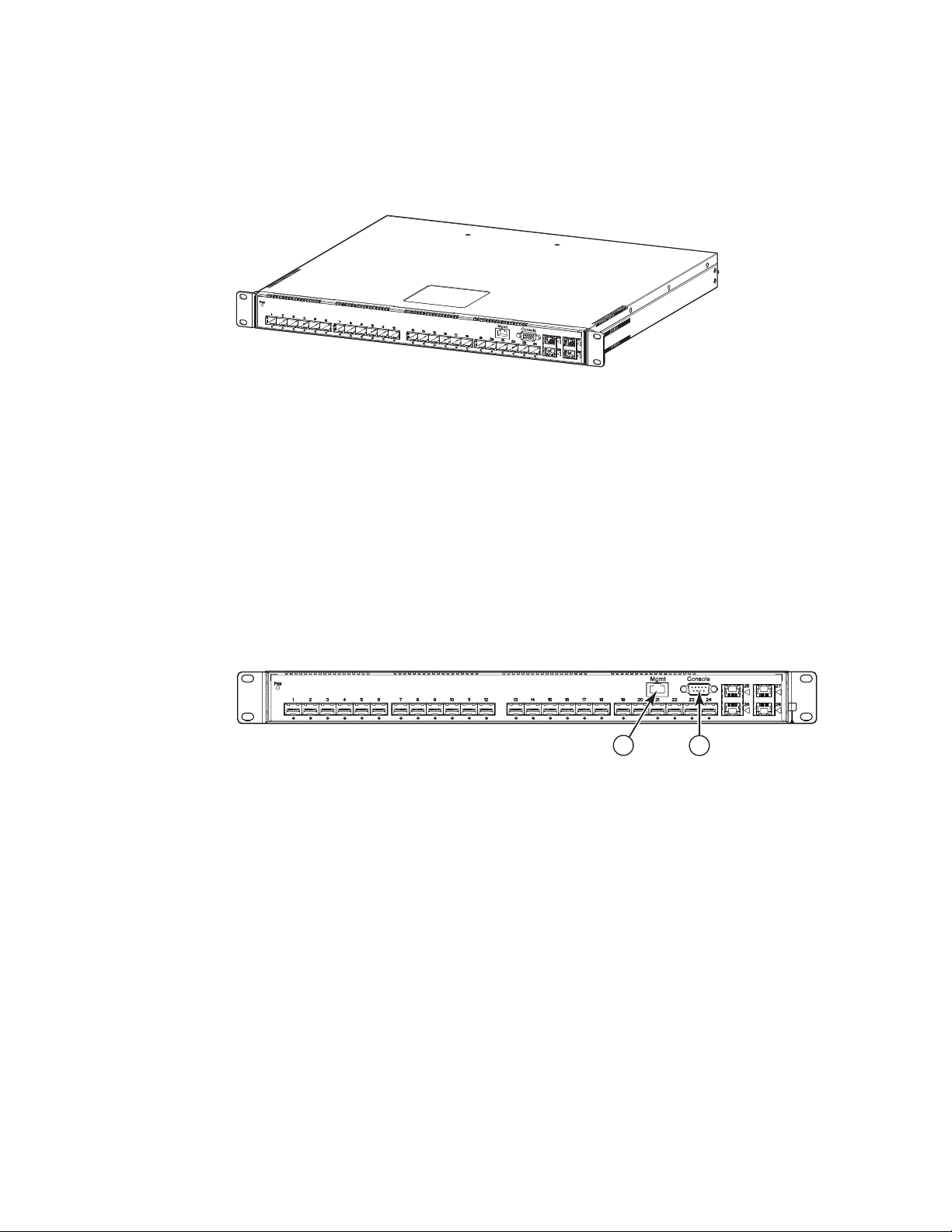
Figure 1 shows the TurboIron 24X.
FIGURE 1 Tur boIro n 24X
TurboIron 24X contains the following ports:
• Twenty-four (24) SFP+ 10 Gigabit and Gigabit Ethernet fiber ports
• Four (4) 10/100/1000 Mbps copper ports, supporting 100Base-TX and 1000Base-T RJ-45
connectors
Control features
TurboIron 24X front panel has the following control features:
• Serial management interface-DB-9 connector interface (Console Port)
• 10/100/1000 RJ-45 Management Port
FIGURE 2 Console and management ports
1 Management Port 2 Console Port
Serial management interface (Console port)
The serial management interface (port labeled Console) enables you to configure and manage the
device using a third-party terminal emulation application on a directly-connected PC,
straight-through EIA or TIA DB-9 serial cable (M/F) is included. The console port is located in the
upper right of the front panel.
Management port
The Management port provides connectivity to your existing management network through
10/100/1000 copper ports that uses auto-sensing and auto-negotiating to determine the speed
(10 Mbps, 100 Mbps, or 1000 Mbps) and mode (full-duplex or half-duplex) of the port at the other
end of the link, and adjusts port speed accordingly. The Management port on the TurboIron 24X
supports RJ-45 copper connectors, auto MDI or MDIX detection, and has an RJ-45 unshielded
twisted pair (UTP) connector.
2 Brocade TurboIron 24X Series Hardware Installation Guide
53-1002981-01
Page 13

Hardware features
NOTE
This port interfaces with the CPU only and not the data plane.
Network interfaces
Tab le 1 describes the network interfaces supported on TurboIron 24X devices.
TABLE 1 Network interfaces
Interface Show Media Description
1000Base-BX-D M-GBXD
1000Base-BX-U M-GBXU
1000Base-LHA M-LHA
1000Base-LHB M-LHB
1000Base-LX M-LX
1000Base-SX M-SX
1000Base-SX2 M-SX2
1000Base-T C
100Base-TX
10GBase-LR XG-LR
10GBase-SR XG-SR
1
Viewing the media types installed in the ports
The show media command displays the types of media (copper or fiber) installed in the ports. The
following example is show media output.
TurboIron# show media
Port 1: Type : 10G XG-SR(SFP+)
Vendor: Brocade Version: 1
Part# : PLRXPLSCS4371 Serial#: xxxxxxxxx
Port 2: Type : EMPTY
Port 3: Type : EMPTY
Port 4: Type : EMPTY
Port 5: Type : EMPTY
Port 6: Type : 10G XG-SR(SFP+)
Vendor: Brocade Version: 1
Part# : PLRXPLSCS4371 Serial#: xxxxxxxxx
Port 7: Type : 10G XG-SR(SFP+)
Vendor: Brocade Version: 1
Part# : PLRXPLSCS4371 Serial#: xxxxxxxxx
Port 8: Type : EMPTY
Port 9: Type : EMPTY
Port 10: Type : EMPTY
Port 11: Type : EMPTY
Port 12: Type : EMPTY
Port 13: Type : 10G XG-SR(SFP+)
Vendor: Brocade Version: 1
Part# : PLRXPLSCS4371 Serial#: xxxxxxxxx
Port 14: Type : 10G XG-SR(SFP+)
Vendor: Brocade Version: 1
Brocade TurboIron 24X Series Hardware Installation Guide 3
53-1002981-01
Page 14
Hardware features
A
1
1
Part# : PLRXPLSCS4371 Serial#: xxxxxxxxx
Port 15: Type : 10G XG-SR(SFP+)
Vendor: Brocade Version: 1
Part# : PLRXPLSCS4371 Serial#: xxxxxxxxx
Port 16: Type : 10G XG-SR(SFP+)
Vendor: Brocade Version: 1
Part# : PLRXPLSCS4371 Serial#: xxxxxxxxx
Port 17: Type : EMPTY
Port 18: Type : EMPTY
Port 19: Type : 10G XG-SR(SFP+)
Vendor: Brocade Version: 1
Part# : PLRXPLSCS4371 Serial#: xxxxxxxxx
Port 20: Type : 10G XG-SR(SFP+)
Vendor: Brocade Version: 1
Part# : PLRXPLSCS4371 Serial#: xxxxxxxxx
Port 21: Type : EMPTY
Port 22: Type : EMPTY
Port 23: Type : EMPTY
Port 24: Type : EMPTY
Port 25: Type : 1G M-C (Gig-Copper)
Port 26: Type : 1G M-C (Gig-Copper)
Port 27: Type : 1G M-C (Gig-Copper)
Port 28: Type : 1G M-C (Gig-Copper)
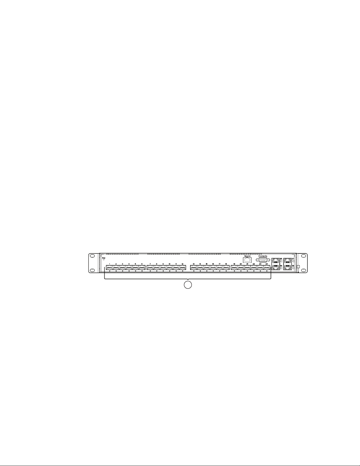
10 Gbps ports
Ports 1 - 24 support 1-GbE SFP transceivers and 10-GbE SFP and SFP+ transceivers listed in
Tab le 1. Figure 3 shows ports 1 - 24.
FIGURE 3 24 10-GbE ports
110-GbE Ports
Four 10/100/1000 Mbps ports
The ports 25~28 are 10/100/1000 copper ports that use auto-sensing and auto-negotiating to
determine the speed (10 Mbps, 100 Mbps, or 1000 Mbps) and mode (full-duplex or half-duplex) of
the port at the other end of the link, and adjust port speed accordingly.
10/100/1000 ports on the TurboIron 24X support RJ-45 copper connectors. The output of the
show media command displays C next to the ports that have copper connectors installed.
Gigabit copper ports on the TurboIron 24X support auto MDI or MDIX detection. For more
information about this feature, refer to "Configuring MDI/MDIX" in the TurboIron Configuration
Guide.
10GbE SFP+ transceiver
TurboIron 24X support a 10GbE SFP+ transceiver specifically for ports 1-24. LEDs on the module
faceplates indicate operational status:
4 Brocade TurboIron 24X Series Hardware Installation Guide
53-1002981-01
Page 15

Hardware features
1
• If the LED is on, the port is connected. If the LED is off, no connection exists, or the link is down
• If the LED is on or blinking, traffic is being transmitted and received on the port
LEDs for network interfaces and power supplies
The fiber and copper ports on TurboIron 24X provide status information through the LEDs listed in
Tab le 2. The LEDs for network interfaces and power supplies are:
• 24 10-Gbps fiber ports (1~24 port) have LEDs located under each of them.
• Four 10/100/1000 copper ports (25~28) have Link and Activity LEDs to indicate port status.
• The Management port has a Link LED and Activity LED to indicate port status. The Link LED is
on the left of the copper connector and the Activity LED is on the right.
• The System power on LED is on the left side of the front panel.
• The dual power supply 1 and 2 LEDs are on the front panel of the power supply (when you are
facing the rear of the device).
TABLE 2 LEDs
LEDs Position State Meaning
10Gbps Port LEDs
LNK or ACT Located under the 10-GbE
ports
10/100/1000 Copper Port LEDs
Lnk This is the left LED on RJ45 On The port is connected.
Act This is the right LED on RJ45 On or Blinking Traffic is being transmitted or
Management Port LEDs
Lnk This is the left LED on RJ45 On The port is connected.
Act This is the right LED on RJ45 On or Blinking Traffic is being transmitted or
System Power and Power Supply LEDs
On The port is connected.
Off No fiber port connection exists or the
link is down.
Blinking Traffic is begin transmitted or
received on the fiber port.
Off No copper port connection exists or
the link is down.
received on the copper port.
Off No traffic is being transmitted or
received on the fiber port.
Off No copper port connection exists or
the link is down.
received on the copper port.
Off No traffic is being transmitted or
received on the fiber port.
Brocade TurboIron 24X Series Hardware Installation Guide 5
53-1002981-01
Page 16
Hardware features
1
1
TABLE 2 LEDs (Continued)
LEDs Position State Meaning
Power On the upper left side of the
front panel (when facing the
front of the device)
AC OK Upper center of power supply's
front panel (when facing the
rear of the device)
On The device is powered on and has
enough power to operate.
Off The device is not powered on, or has
been powered on but does not have
sufficient power to operate.
On Indicated power supply is installed
and is functioning normally.
NOTE: Power supply 1 is located in
the right-hand bay and power
supply 2 in the left-hand bay
(when facing the rear of the
device).
Off Power supply is not installed or is not
providing power.
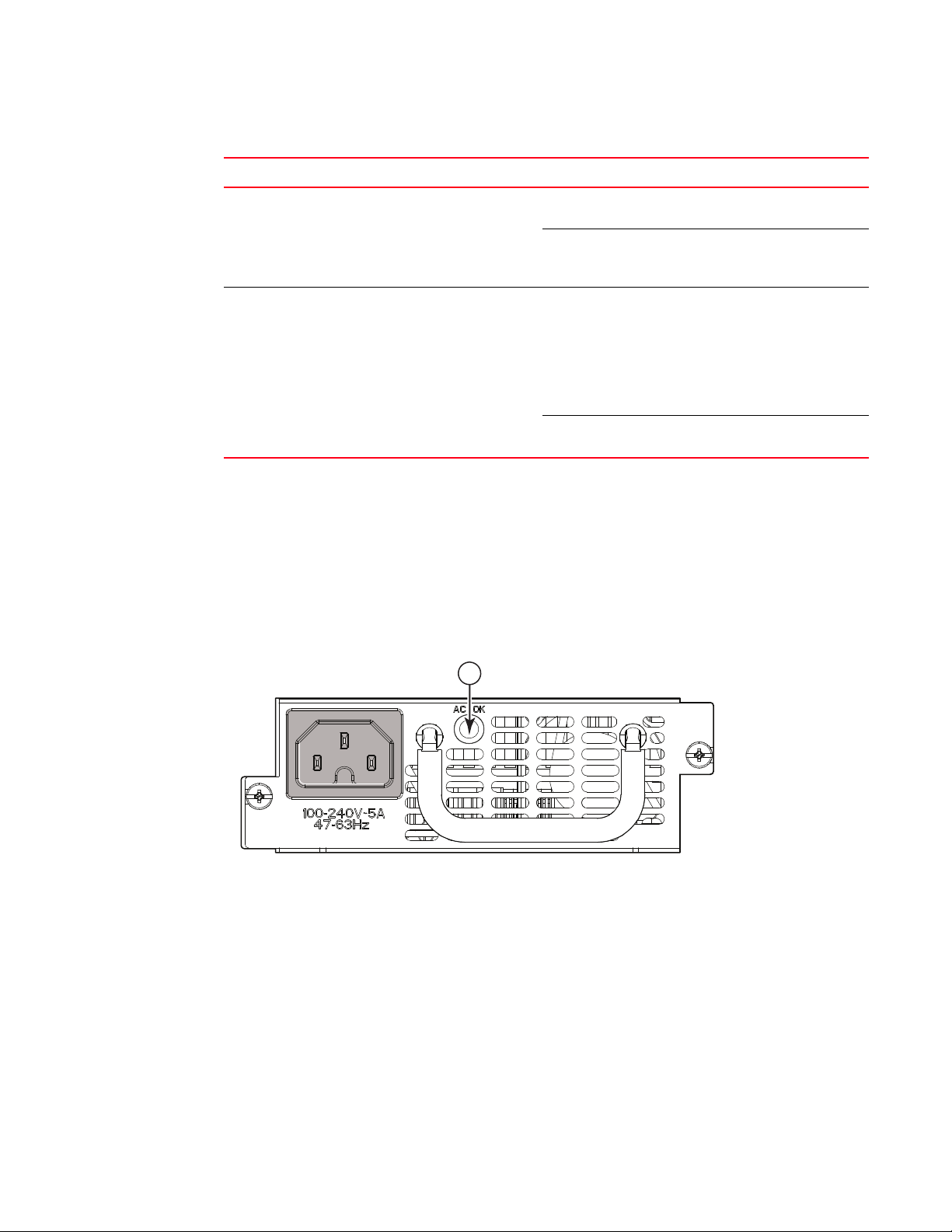
Power supplies
Each TurboIron 24X device comes with dual alternating-current (AC) power supplies (RPS-TI24X).
Power supplies are hot-swappable.
Figure 4 shows the front panel of the AC power supplies used in the TurboIron 24X (at the rear of
the device).
FIGURE 4 AC power supply front panel
1AC LED
The power supplies are auto-sensing and auto-switching, and provide up to 300 watts of total
output power, having a universal input (90 VAC to 264 VAC) and 12 VDC regulated output.
Power supplies can be swapped in or out of the device while the device is running, and without
opening the device. You can remove one of the supplies without interrupting operation because the
remaining power supply provides enough power for all of the ports.
For power supply hardware specifications, refer to “Power supply specifications” on page 55.
6 Brocade TurboIron 24X Series Hardware Installation Guide
53-1002981-01
Page 17
Hardware features
CAUTION
CAUTION
Disconnect the power supply cable from the power source (outlet) before you install it in or
remove it from the device. Failure to do this can result in damage to the power supply or the
device, or both (the device can be running while a power supply is being installed or removed, but
the power supply itself should not be connected to a power source).
The TurboIron 24X power supply is designed exclusively for use with TurboIron 24X. Installing the
power supply in a device other than a TurboIron 24X will cause extensive damage to your
equipment.
1
Brocade TurboIron 24X Series Hardware Installation Guide 7
53-1002981-01
Page 18

Hardware features
1
8 Brocade TurboIron 24X Series Hardware Installation Guide
53-1002981-01
Page 19

Chapter
DANGER
Installing the TurboIron 24X
This chapter contains the following sections:
•Unpacking a system . . . . . . . . . . . . . . . . . . . . . . . . . . . . . . . . . . . . . . . . . . . . . 9
•Summary of installation tasks . . . . . . . . . . . . . . . . . . . . . . . . . . . . . . . . . . . . 10
•Installation precautions . . . . . . . . . . . . . . . . . . . . . . . . . . . . . . . . . . . . . . . . . 11
•Preparing the installation site. . . . . . . . . . . . . . . . . . . . . . . . . . . . . . . . . . . . . 14
•Installing the device . . . . . . . . . . . . . . . . . . . . . . . . . . . . . . . . . . . . . . . . . . . . 15
•Powering on the system . . . . . . . . . . . . . . . . . . . . . . . . . . . . . . . . . . . . . . . . . 18
•Verifying proper operation. . . . . . . . . . . . . . . . . . . . . . . . . . . . . . . . . . . . . . . . 19
•Attaching a PC or terminal . . . . . . . . . . . . . . . . . . . . . . . . . . . . . . . . . . . . . . . 20
Unpacking a system
2
The procedures in this manual are intended for qualified service personnel.
Information about configuring IP addresses and connecting network devices is in the Chapter 3,
“Connecting Network Devices and Checking Connectivity”.
Brocade TurboIron systems ship with all of the items listed below. Please review the list and verify
the contents. If any items are missing, please contact the place of purchase.
Package contents
Verify the package contents listed below:
• Brocade TurboIron 24X device with dual AC power supplies installed
• AC power cord
• Rack mount brackets and mounting screws (already secured on the device)
General requirements
To manage the system, you will need the following items for serial connection to a Layer 2 or Layer
3 switch:
• A management station, such as a PC running a terminal emulation application.
Brocade TurboIron 24X Series Hardware Installation Guide 9
53-1002981-01
Page 20

Summary of installation tasks
2
• A straight-through EIA or TIA DB-9 serial cable (F/F). This cable can be ordered separately from
Brocade. If you prefer to build your own cable, refer to the pinout information in “Attaching a PC
or terminal” on page 20.
• Use the serial connection to perform basic configuration tasks, such as assigning an IP
address and network mask. This information is required to manage the system using the
Brocade Network Advisor or using the CLI through Telnet.
Summary of installation tasks
Follow the steps listed below to install your TurboIron 24X device. Details for each of these steps
are provided in this chapter and in the following chapter.
TABLE 3 Summary of installation tasks
Task No. Task Where to Find More Information
1 Ensure that the physical environment where the device will be
installed has the proper cabling and ventilation.
2 Install the Brocade device on a desktop or in an equipment rack.
Devices may also be wall-mounted.
3 When the device is installed, plug the power cord into a nearby
power source that adheres to the regulatory requirements outlined
in this manual.
4 Verify that power LED is on after the system is powered-on. “Verifying proper operation” on
5 Attach a terminal or PC to the Brocade device. This enables you to
configure the device through the Command Line Interface (CLI).
6 No default password is assigned to the CLI. For additional access
security, assign a password.
7 Before attaching equipment to the device, you must configure an
interface IP address to the subnet on which it will be located. Initial
IP address configuration is performed using the CLI with a direct
serial connection.
8 Once you power-on the device and assign IP addresses, the system
is ready to accept network equipment.
9 Test IP connectivity by pinging other devices and tracing routes. “Testing connectivity” on
10 Continue configuration using the CLI. You also can use Brocade
Network Advisor to manage the device.
11 Secure access to the device. TurboIron Configuration Guide
“Preparing the installation site”
on page 14
“Installing the device” on
page 15
“Powering on the system” on
page 18
page 19
“Attaching a PC or terminal” on
page 20
“Assigning permanent
passwords” on page 23
“Configuring IP addresses” on
page 25
“Connecting network devices”
on page 26
page 29
TurboIron Configuration Guide
10 Brocade TurboIron 24X Series Hardware Installation Guide
53-1002981-01
Page 21
Installation precautions
CAUTION
CAUTION
CAUTION
CAUTION
CAUTION
DANGER
Follow these precautions when installing a Brocade device.
General precautions
Do not install the device in an environment where the operating ambient temperature might
exceed 40°C (104°F).
Make sure that air flow around the front, sides, and back of the device is not restricted.
Installation precautions
2
Never leave tools inside the device.
Use the erase startup-config command only for new systems. If you enter this command on a
system you have already configured, the command erases the configuration. If you accidentally
do erase the configuration on a configured system, enter the write memory command to save the
running configuration to the startupconfig file.
Changes or modifications made to this device that are not expressly approved by the party
responsible for compliance could void the user's authority to operate the equipment.
All fiber-optic interfaces use Class 1 lasers.
Brocade TurboIron 24X Series Hardware Installation Guide 11
53-1002981-01
Page 22
Installation precautions
DANGER
DANGER
DANGER
CAUTION
CAUTION
CAUTION
2
Lifting precautions
Make sure the rack or cabinet housing the device is adequately secured to prevent it from
becoming unstable or falling over.
Do not use the handles on the power supply units to lift or carry a Brocade device.
Mount the devices you install in a rack or cabinet as low as possible. Place the heaviest device at
the bottom and progressively place lighter devices above.
Power precautions
The following precautions apply to TurboIron 24X devices:
Use a separate branch circuit for each AC power cord, to provide redundancy in case one of the
circuits fails.
Ensure that the device does not overload the power circuits, wiring, and over-current protection.
To determine the possibility of overloading the supply circuits, add the ampere (amp) ratings of all
devices installed on the same circuit as the device. Compare this total with the rating limit for the
circuit. The maximum ampere ratings are usually printed on the devices near the input power
connectors.
Make sure you insert the power supply right-side up. It is possible to insert the supply upside
down, although the supply will not engage with the power backplane cotter pin when plugged
upside down. The label of the power supply is on the top when you plug in the power supply
right-side up when the power connector is on the left and the fan vent is on the right.
12 Brocade TurboIron 24X Series Hardware Installation Guide
53-1002981-01
Page 23
Installation precautions
CAUTION
CAUTION
CAUTION
DANGER
DANGER
DANGER
Remove the power cord from a power supply before you install it in or remove it from the device.
Otherwise, the power supply or the device could be damaged (the device can be running while a
power supply is being installed or removed, but the power supply itself should not be connected
to a power source).
The TurboIron 24X power supply is designed exclusively for use with TurboIron 24X devices.
Installing the power supply in a device other than the TurboIron 24X will cause extensive damage
to your equipment.
Risk of explosion if battery is replaced by an incorrect type. Replace the battery only with the
same or equivalent type recommended by the manufacturer. Dispose of used battery according
to the instructions.
2
Disconnect the power cord from all power sources to completely remove power from the device.
Make sure to choose the appropriate circuit device depending on the number of AC power
supplies installed in the device. The minimum current draw for the system is one AC power
supply.
Power supplies are hot swappable. However, Brocade recommends that you disconnect the
power supply from AC power before installing or removing the supply. The device can be running
while a power supply is being installed or removed, but the power supply itself should not be
connected to a power source. Otherwise, you could be injured or the power supply or other parts
of the device could be damaged.
Brocade TurboIron 24X Series Hardware Installation Guide 13
53-1002981-01
Page 24
Preparing the installation site
DANGER
DANGER
DANGER
2
Make sure that the power source circuits are properly grounded, then use the power cord
supplied with the device to connect it to the power source.
If the installation requires a different power cord than the one supplied with the device, make
sure you use a power cord displaying the mark of the safety agency that defines the regulations
for power cords in your country. The mark is your assurance that the power cord can be used
safely with the device.
For safety reasons, the ESD wrist strap should contain a series 1 MB ohm resistor.
Preparing the installation site
Cabling infrastructure
Ensure that the proper cabling is installed in the site. Refer to “Device specifications” on page 50
or visit http://www.brocade.com for a summary of supported cabling types and their specifications.
Installation location
Before installing the device, plan its location and orientation relative to other devices and
equipment. Allow at least 3 in. of space at the front of the device for the twisted-pair, fiber-optic,
and power cabling. Also, allow a minimum of 3 in. of space between the sides and the back of the
device and walls or other obstructions.
14 Brocade TurboIron 24X Series Hardware Installation Guide
53-1002981-01
Page 25
Installing the device
DANGER
DANGER
DANGER
DANGER
You can install Brocade TurboIron devices on a desktop or in an equipment rack.
Make sure the rack or cabinet housing the device is adequately secured to prevent it from
becoming unstable or falling over.
Mount devices in a rack or cabinet as low as possible. Place the heaviest device at the bottom
and progressively lighter devices above.
Desktop installation
Follow the steps for desktop installation.
Installing the device
2
1. Set the device on a flat desktop, table, or shelf. Make sure that adequate ventilation is
provided for the system. A 3 in. clearance is recommended on each side.
2. Proceed to “Powering on the system” on page 18.
Rack mount installation
For rack mount installation, the Brocade TurboIron 24X supports the use of a two post Telco
equipment rack.
A rack mount kit with short mounting brackets ships with the device.
In addition to the rack mount kit, you will need the following tools for installation:
• #2 Phillips-head screwdriver
• Four 12-24 screws to mount the Brocade device in the rack.
Make sure the rack or cabinet housing the device is adequately secured to prevent it from
becoming unstable or falling over.
Mount the devices you install in a rack or cabinet as low as possible. Place the heaviest device at
the bottom and progressively place lighter devices above.
Brocade TurboIron 24X Series Hardware Installation Guide 15
53-1002981-01
Page 26
Installing the device
DANGER
DANGER
DANGER
DANGER
DANGER
2
Mechanical Loading - Mounting of the equipment in the rack should be such that a hazardous
condition is not achieved due to uneven mechanical loading.
Elevated Operating Ambient - If installed in a closed or multi-unit rack assembly, the operating
ambient temperature of the rack environment may be greater than room ambient. Therefore,
consideration should be given to installing the equipment in an environment compatible with the
maximum ambient temperature (Tma) specified by the manufacturer.
Reduced Air Flow - Installation of the equipment in a rack should be such that the amount of air
flow required for safe operation of the equipment is not compromised.
Circuit Overloading - Consideration should be given to the connection of the equipment to the
supply circuit and the effect that overloading of the circuits might have on overcurrent protection
and supply wiring. Appropriate consideration of equipment nameplate ratings should be used
when addressing this concern.
Reliable Earthing - Reliable earthing of rack-mounted equipment should be maintained.
Particular attention should be given to supply connections other than direct connections to the
branch circuit (e.g., use of power strips).
16 Brocade TurboIron 24X Series Hardware Installation Guide
53-1002981-01
Page 27

Installing the device
DANGER
Follow the steps to install the rack mount brackets and mount the device in a rack.
1. Remove the rack mount kit from the shipping carton. The kit contains two mounting brackets.
2. Place the Network switch on a hard flat surface with the front panel facing you.
3. Attach a rack-mount bracket to one side of the Network switch with the supplied screws. Then
attach the other bracket to the other side.
Make sure you use the screws supplied with the mounting brackets. Using the wrong screws
could damage the TurboIron 24X and would invalidate your warranty.
Figure 5 shows how to attach the short mounting brackets.
2
FIGURE 5 Attaching the short mounting brackets
Mount the device in the rack as illustrated in Figure 6.
Brocade TurboIron 24X Series Hardware Installation Guide 17
53-1002981-01
Page 28

Powering on the system
NOTE
2
FIGURE 6 Installing the device in a rack
4. Proceed to “Powering on the system”.
Powering on the system
Note the following before powering on the system:
• The socket should be installed near the equipment and should be easily accessible.
• If the outlet is not rated 115 or 120V, stop and get the appropriate cable for the outlet.
• If your installation requires a different power cord than that supplied with the device, make
sure you obtain a power cord displaying the mark of the safety agency that defines the
regulations for power cords in your country. The mark is your assurance that the power cord
can be used safely with the device.
• Ensure that all power supplies are fully and properly inserted.
• Remove the power cord from the shipping package.
• Attach the AC power cord to the AC connector on the rear panel as shown in Figure 7.
Align the locating notch on the underside of the AC power cord before inserting.
• Insert the power cord plug into a properly grounded 115V or 120V electrical outlet.
18 Brocade TurboIron 24X Series Hardware Installation Guide
53-1002981-01
Page 29

Verifying proper operation
FIGURE 7 Attaching the AC power cord
• Repeat this procedure for the second power supply.
• Verify the device is working properly (refer to “Verifying proper operation”.)
2
Powering off the system
To turn an AC system OFF:
• Unplug the power cords from the power source.
Verifying proper operation
After you have installed any additional power supplies and powered on the system, verify that the
device is working properly.
1. Verify that the LEDs on the power supply and system power LED are solid green.
2. Verify proper operation by observing the LEDs on the front panel.
10G port LEDs should be lit while the device performs diagnostics. After the diagnostics are
complete, the LEDs will be dark except for those that are attached by cables to other devices.
If the links on these cables are good and the connected device is powered on, the link LEDs will
light. Table 4 provides more details on specific LED conditions after system start-up.
Observing the power status LEDs
Tab le 4 lists the device LEDs that show power status.
Brocade TurboIron 24X Series Hardware Installation Guide 19
53-1002981-01
Page 30

Attaching a PC or terminal
NOTE
2
TABLE 4 Power LEDs
LEDs Position State Meaning
Pwr (Power) Left-most LED on the
front panel
AC OK On power supply 1 front
panel
AC OK On power supply 2 front
panel
The software regularly polls the hardware for power status information. You can display the status
information from any management session using the show chassis CLI command. In addition, the
software automatically generates a Syslog message and SNMP trap if a status change occurs.
Attaching a PC or terminal
On The device is powered on and has enough
power to operate.
Off The device is not powered on, or has been
powered on but does not have sufficient
power to operate.
On Power supply 1 is installed and is functioning
normally. Power supply 1 is located in the
right-hand bay (when you are facing the rear
of the device).
Off Power supply 1 is not installed or is not
providing power.
On Power supply 2 is installed and is functioning
normally. Power supply 2 is located in the lefthand bay (when you are facing the rear of the
device).
Off Power supply 2 is not providing power.
To assign an IP address, you must have access to the Command Line Interface (CLI). The CLI is a
text-based interface that can be accessed through a direct serial connection to the device or
through Telnet connections.
You will need to assign an IP address using the CLI. You can access the CLI by attaching
management station through a serial cable to the Console port. After you assign an IP address, you
can access the system through Telnet or Brocade Network Advisor.
Follow the steps to attach a management station using the serial port.
1. Use a straight-through cable to connect a PC or terminal to the male DB-9 serial port
connector.
You need to run a terminal emulation program on the PC.
2. Open the terminal emulation program and set the session parameters as follows:
• Baud: 9600 bps
• Data bits: 8
• Parity: None
• Stop bits: 1
• Flow control: None
When you establish the serial connection to the system, press Enter to display the CLI prompt in the
terminal emulation window. For example,
20 Brocade TurboIron 24X Series Hardware Installation Guide
53-1002981-01
Page 31

Attaching a PC or terminal
Pin Assignment
DB-9 mal
Pin Number
Switch Signal
6
1 Reserved
2 TXD (output)
3 RXD (input)
4 Reserved
5 GND
6 Reserved
7 Reserved
8 Reserved
9 Reserved
1 5
9
e
TurboIron>
2
When you see one of these prompts, you are connected to the system and can proceed to
“Assigning permanent passwords” on page 23.
You can customize the prompt by changing the system name. Refer to the TurboIron Configuration
Guide.
If you do not see a prompt:
• Make sure the cable is securely connected to your PC and to the Brocade device.
• Check the settings in your terminal emulation program. In addition to the session settings
listed above, make sure the terminal emulation session is running on the same serial port you
attached to the Brocade device.
The EIA or TIA 232 serial communication port serves as a connection point for management by a
PC or SNMP workstation. Brocade switches and Layer 3 Switches come with a standard male DB-9
connector, shown in Figure 8.
FIGURE 8 Serial port pin and signalling details
Most PC serial ports also require a cable with a female DB-9 connector.
Terminal connections will vary, requiring either a DB-9 or DB-25 connector, male or female.
Serial cable options between a Brocade switch or router and a PC or terminal are shown in
Figure 9.
Brocade TurboIron 24X Series Hardware Installation Guide 21
53-1002981-01
Page 32

Attaching a PC or terminal
NOTE
1
2
3
4
5
6
7
8
9
1
2
3
4
5
6
7
8
9
8
3
2
20
7
6
4
5
22
1
2
3
4
5
6
7
8
9
DB-9 to DB-9
Female Switch
Terminal or PC
Reserved
Reserved
Reserved
Reserved
DB-9 to DB-25
Female Switch
Terminal or PC
Reserved
Reserved
Reserved
Reserved
2
FIGURE 9 Serial port pin assignments showing cable connection options to a terminal or PC
As indicated in Figure 8 and Figure 9, some of the wires should not be connected. If you do connect
the wires that are labeled "Reserved", you might get unexpected results with some terminals.
22 Brocade TurboIron 24X Series Hardware Installation Guide
53-1002981-01
Page 33

Chapter
DANGER
NOTE
NOTE
Connecting Network Devices and Checking Connectivity
This chapter contains the following sections:
•Assigning permanent passwords . . . . . . . . . . . . . . . . . . . . . . . . . . . . . . . . . . 23
•Configuring IP addresses . . . . . . . . . . . . . . . . . . . . . . . . . . . . . . . . . . . . . . . . 25
•Connecting network devices. . . . . . . . . . . . . . . . . . . . . . . . . . . . . . . . . . . . . . 26
•Testing connectivity . . . . . . . . . . . . . . . . . . . . . . . . . . . . . . . . . . . . . . . . . . . . . 29
•Troubleshooting network connections . . . . . . . . . . . . . . . . . . . . . . . . . . . . . . 31
Assigning permanent passwords
The procedures in this manual are intended for qualified service personnel.
3
This chapter provides the details for connecting network devices and checking network
connectivity.
By default, the CLI is not protected by passwords. To secure CLI access, Brocade strongly
recommends assigning passwords.
You can assign passwords using Brocade Network Advisor if an enable password for a Super User
has been configured on the device.
The CLI contains the following access levels:
• User EXEC—The level you enter when you first start a CLI session. At this level, you can view
some system information but you cannot configure system or port parameters.
• Privileged EXEC—Also called the Enable level, and can be secured by a password. At this level,
you can perform tasks such as manage files on the flash module, save the system
configuration to flash, and clear caches.
• CONFIG—This level lets you configure the system IP address, and switching and routing
features. To access the CONFIG mode, you must already be logged into the Privileged level of
the EXEC mode (the Enable level).
You can set the following levels of Enable passwords:
• Super User - Allows complete read-and-write access to the system. This is generally for system
administrators and is the only password level that allows you to configure passwords.
You must set a Super User password before you can set other types of passwords.
Brocade TurboIron 24X Series Hardware Installation Guide 23
53-1002981-01
Page 34

Assigning permanent passwords
NOTE
NOTE
NOTE
3
• Port Configuration - Allows read-and-write access for specific ports but not for global
(system-wide) parameters.
• Read Only - Allows access to the Privileged EXEC mode and CONFIG mode but only with read
access.
Follow the steps to set passwords.
1. At the opening CLI prompt, enter the following command to change to the Privileged level of the
EXEC mode.
TurboIron> enable
2. Access the configuration level of the CLI by entering the following command.
TurboIron# configure terminal
TurboIron(config)#
3. Enter the following command to set the Super User password.
TurboIron# enable super-user-password text
You must set the Super User password before you can set other types of passwords.
4. Enter the following commands to set the port configuration and read-only passwords.
TurboIron(config)# enable port-config-password text
TurboIron(config)# enable read-only-password text
If you forget your Super User password, refer to “Recovering from a lost password”.
Syntax: enable super-user-password | read-only-password | port-config-password text
Passwords can be up to 32 characters long.
Recovering from a lost password
By default, the CLI does not require passwords. However, if someone has configured a password for
the device but the password has been lost, you can regain Super User access to the device using
the following procedure.
Recovery from a lost password requires direct access to the serial port and a system reset.
Follow the steps to recover from a lost password.
1. Start a CLI session over the serial interface to the Brocade device.
2. Reboot the device.
3. While the system is booting, before the initial system prompt appears, enter b to enter the boot
monitor mode.
4. Enter no password at the prompt. (You cannot abbreviate this command.)
5. Enter boot system flash primary at the prompt. This command causes the device to bypass the
system password check.
6. After the console prompt reappears, assign a new password.
24 Brocade TurboIron 24X Series Hardware Installation Guide
53-1002981-01
Page 35

Configuring IP addresses
CAUTION
NOTE
You must configure at least one IP address using the serial connection to the CLI before you can
manage the system using the other management interfaces. In addition, Brocade routers require
an IP subnet address for the subnet in which you plan to place them in your network.
Brocade devices support both classical IP network masks (Class A, B, and C subnet masks, and so
on) and Classless Interdomain Routing (CIDR) and network prefix masks as follows:
• To enter a classical network mask, enter the mask in IP address format. For example, enter,
"10.157.22.99 255.255.255.0" for an IP address with a Class-C subnet mask.
• To enter a prefix number for a network mask, enter a forward slash ( /) and the number of bits
in the mask immediately after the IP address. For example, enter,
"10.157.22.99/24" for an IP address that has a network mask with 24 significant ("mask") bits.
By default, the CLI displays network masks in classical IP address format (example:
255.255.255.0). You can change the display to the prefix format. Refer to the Turbo Iron
Configuration Guide.
Devices running Layer 2 software
Configuring IP addresses
3
Follow the steps to configure an IP address on a device running Layer 2 software.
1. At the opening CLI prompt, enter enable.
TurboIron> enable
2. Enter the following command at the Privileged EXEC level prompt (for example, TurboIron
Switch#), then press Enter. This command erases the factory test configuration if still present.
TurboIron# erase startup-config
Use the erase startup-config command only for new systems. If you enter this command on a
system you have already configured, the command erases the configuration. If you accidentally
do erase the configuration on a configured system, enter the write memory command to save the
running configuration to the startup-config file.
3. Access the CONFIG level of the CLI by entering the following command.
TurboIron# configure terminal Privileged EXEC Level
TurboIron(config)# Global CONFIG Level
4. Configure the IP address and mask for the switch.
TurboIron(config)# ip address 10.22.3.44 255.255.255.0
5. Set a default gateway address for the switch.
TurboIron(config)# ip default-gateway 10.22.3.1
You do not need to assign a default gateway address for single subnet networks.
Syntax: enable [password]
Brocade TurboIron 24X Series Hardware Installation Guide 25
53-1002981-01
Page 36

Connecting network devices
NOTE
3
Syntax: configure terminal
Syntax: [no] ip address ip-addr ip-mask
or
Syntax: [no] ip address ip-addr/mask-bits
Syntax: ip default-gateway ip-addr
Connecting network devices
Brocade devices support connections to routers, switches, and hubs from other vendors, as well as
other Brocade devices.
Connectors and cable specifications
Refer to “Cable specifications” on page 53 for cable lengths and types supported on the TurboIron
24X devices. For port pinouts, refer to “10/100/1000 Gigabit port pinouts” on page 53.
Connecting to Ethernet or fast Ethernet hubs
For copper connections to Ethernet hubs, a 10/100Base-TX or 1000Base-T switch, or another
Brocade device, a crossover cable is required (Figure 10 and Figure 11). If the hub is equipped with
an uplink port, it will require a straight-through cable instead of a crossover cable.
The 802.3ab standard (automatic MDI or MDIX detection) calls for automatic negotiation of the
connection between two 1000Base-T ports. Therefore, a crossover cable may not be required; a
straight-through cable may work as well. For more information about this feature, refer to the
TurboIron Configuration Guide.
26 Brocade TurboIron 24X Series Hardware Installation Guide
53-1002981-01
Page 37

FIGURE 10 UTP crossover cable
NOTE
11
22
33
66
4
5
7
11
22
33
6
8
44
5
7
8
1
8
UTP Crossover Cable 10/100BaseTX
- Unused
Unused - - Unused
Unused -
Unused -
Unused -
- Unused
- Unused
11
22
33
66
88
44
5
7
5
7
1
8
Cat-5 Crossover Cable 1000BaseT
FIGURE 11 Cat-5 crossover cable for 1000Base-T
Connecting network devices
3
Brocade TurboIron 24X Series Hardware Installation Guide 27
53-1002981-01
The 802.3ab standard calls for automatic negotiation of the connection between two 1000Base-T
ports. Consequently, a crossover cable may not be required; a straight-through cable may work as
well.
Connecting to workstations, servers, or routers
Straight-through UTP cabling is required for direct UTP attachment to workstations, servers, or
routers using network interface cards (NICs).
Fiber cabling is required for direct attachment to Gigabit NICs or switches and routers through fiber
ports. Refer to “Connecting a network device to a fiber port”.
Automatic MDI or MDIX detection
All 10/100/1000 Copper ports on the Brocade TurboIron 24X devices support automatic Media
Dependent Interface (MDI) and Media Dependent Interface Crossover (MDIX) detection. This
feature is enabled on all Gigabit copper ports by default. For each port, you can disable auto MDI or
MDIX, designate the port as an MDI port, or designate the port as an MDIX port.
For more information about this feature and how configure it, refer to the TurboIron Configuration
Guide.
Page 38

Connecting network devices
DANGER
3
Connecting a network device to a fiber port
For direct attachment from the Brocade device to a Gigabit NIC, switch, or router, fiber cabling with
an LC connector is required.
To connect the Brocade device to another network device using a fiber port, you must do the
following:
• Install a fiber optic module (SFP transceiver or mini-GBIC for Gigabit Ethernet ports, or SFP+
• Cable the fiber optic module
The following sections provide information about performing these tasks.
Installing a fiber optic module
You must install a fiber optic module (SFP or SFP+ transceiver) in each Gigabit Ethernet and
10-Gigabit Ethernet fiber port you want to use.
You can install a new fiber optic module in a port while the Brocade device is powered on and
running.
To install a fiber optic module, you will need an ESD wrist strap with a plug for connection to a metal
surface.
transceiver for 10-Gigabit Ethernet ports)
For safety reasons, the ESD wrist strap should contain a series 1 meg ohm resistor.
Follow the steps to install a fiber optic module.
1. Put on the ESD wrist strap and ground yourself by attaching the clip end to a metal surface
(such as an equipment rack) to act as ground.
2. Remove the new module from its protective packaging.
3. Gently insert the fiber optic module into the port until the module clicks into place. The module
is keyed to prevent incorrect insertion.
Cabling a fiber optic module
Follow the steps to cable a fiber optic module.
1. Remove the protective covering from the fiber-optic port connectors and store the covering for
future use.
2. Before cabling a fiber optic module, Brocade strongly recommends that the cable connectors
and the port connectors are cleaned thoroughly. For more information, refer to “Cleaning the
fiber-optic connectors”.
3. Gently insert the cable connector or connectors (a tab on each connector should face upward)
into the port connector or connectors until the tabs lock into place.
4. Observe the link and active LEDs to determine if the network connections are functioning
properly. Refer to Tab le 5.
28 Brocade TurboIron 24X Series Hardware Installation Guide
53-1002981-01
Page 39

Cleaning the fiber-optic connectors
NOTE
To avoid problems with the connection between the fiber optic module (SFP (mini-GBIC) or SFP+)
and the fiber cable connectors, Brocade strongly recommends that both connectors are cleaned
thoroughly each time you disconnect and reconnect them. In particular, dust can accumulate in the
connectors and cause problems such as reducing the optic launch power.
To clean the fiber cable connectors, Brocade recommends that you use the fiber-optic cleaner that
shipped with your Brocade device. You can also purchase this type of cleaner from the following
Website.
http://www.fisfiber.com
When not using an SFP or SFP+ connector, make sure to keep the protective covering on.
Testing connectivity
After you install the network cables, you can test network connectivity to other devices by pinging
those devices. You also can observe the LEDs related to network connection and perform trace
routes.
Testing connectivity
3
Pinging an IP address
To verify that a TurboIron device can reach another device through the network, enter a command
such as the following at any level of the CLI on the TurboIron device.
TurboIron> ping 10.33.4.7
Syntax: ping ip addr | hostname [source ip addr] [count num] [timeout msec] [ttl num] [size byte]
[quiet] [numeric] [no-fragment] [verify] [data 1-to-4 byte hex] [brief]
If you address the ping to the IP broadcast address, the device lists the first four responses to the
ping.
Observing LEDs
After you install the network cables, you can observe certain LEDs to determine if the network
connections are functioning properly. Tab le 5 describes the LEDs related to network connections,
the desired state of each LED, possible abnormal states of each LED, and what to do if an LED
indicates an abnormal state.
Brocade TurboIron 24X Series Hardware Installation Guide 29
53-1002981-01
Page 40

Testing connectivity
3
TABLE 5 Network connection-related LED states
LED Desired State Meaning Abnormal
State
Meaning or Action
Link
(Lnk)
Active
(Act)
On (Green) A link is established
with the remote port.
On or blinking
(Yellow)
The port is
transmitting and
receiving user
packets.
Off A link is not established with the remote port.
You can do the following:
• Verify that the connection to the other
network device has been properly made.
Also, make certain that the other
network device is powered on and
operating correctly.
• Verify that the transmit port on the
Brocade device is connected to the
receive port on the other network device,
and that the receive port on the Brocade
device is connected to the transmit port
on the other network device. If you are
uncertain, remove the two cable
connectors from the port connector and
reinsert them in the port connector,
reversing their order.
• Dust may have accumulated in the cable
connector or port connector. For
information about cleaning the
connectors, refer to “Cleaning the
fiber-optic connectors”.
• If the other actions don't resolve the
problem, try using a different port or a
different cable.
Off for an
extended
period.
The port is not transmitting or receiving user
packets. You can do the following:
• Check the Link LED to make sure the link
is still established with the remote port.
If not, take the actions described in the
Meaning or Action column for the Link
LED.
• Verify that the port has not been
disabled through a configuration
change. You can use the CLI. If you have
configured an IP address on the device,
you also can use Brocade Network
Advisor.
If a problem persists after taking these actions, contact TurboIron technical support.
30 Brocade TurboIron 24X Series Hardware Installation Guide
53-1002981-01
Page 41

Tracing a route
To determine the path through which a TurboIron device can reach another device, enter a
command such as the following at any level of the CLI on the TurboIron device.
TurboIron> traceroute 10.33.4.7
Syntax: traceroute host-ip-addr [maxttl value] [minttl value] [numeric] [timeout value] [source-ip ip
addr]
The CLI displays trace route information for each hop as soon as the information is received.
Traceroute requests display all responses to a given TTL. In addition, if there are multiple equal-cost
routes to the destination, the Brocade device displays up to three responses by default.
Troubleshooting network connections
• For the indicated port, verify that both ends of the cabling (at the TurboIron device and the
connected device) are snug.
• Verify that the TurboIron device and the connected device are both powered on and operating
correctly.
• Verify that you have used the correct cable type for the connection:
• For twisted-pair connections to an end node, use straight-through cabling.
• For fiber-optic connections, verify that the transmit port on the device is connected to the
receive port on the connected device, and that the receive port on the device is connected
to the transmit port on the connected device.
• Verify that the port has not been disabled through a configuration change. You can use the CLI.
If you have configured an IP address on the device, you also can use Brocade Network Advisor.
• For copper ports, you can test the cable using Virtual Cable Testing (VCT). Refer to "Monitoring
Hardware Components" in the TurboIron Configuration Guide.
• If the other procedures don't resolve the problem, try using a different port or a different cable.
Troubleshooting network connections
3
Support for digital optical monitoring
You can configure your TurboIron device to monitor optical transceivers in the system, either
globally or by specified port. When this feature is enabled, the system monitors the temperature
and signal power levels for the optical transceivers in the specified ports. Console messages and
syslog messages are sent when optical operating conditions fall below or rise above the SFP+ or
SFP manufacturer recommended thresholds. For more information about digital optical monitoring,
refer to the TurboIron Configuration Guide.
Brocade TurboIron 24X Series Hardware Installation Guide 31
53-1002981-01
Page 42

Troubleshooting network connections
3
32 Brocade TurboIron 24X Series Hardware Installation Guide
53-1002981-01
Page 43

Chapter
Managing the TurboIron 24X
This chapter contains the following sections:
•Managing temperature settings . . . . . . . . . . . . . . . . . . . . . . . . . . . . . . . . . . . 33
•Removing MAC address entries . . . . . . . . . . . . . . . . . . . . . . . . . . . . . . . . . . . 35
Managing temperature settings
This section describes how to display temperature settings on the TurboIron 24X and how to
change the temperature warning levels.
Using the temperature sensor
The TurboIron 24X comes with two built-in temperature sensors; one at the air intake, and the other
at the exhaust (refer to Figure 25 on page 51). The temperature sensor at the air intake monitors
the incoming air temperature. The temperature sensor at the air exhaust monitors the air
temperature as it exits the device. The temperature sensors cause the device to generate a Syslog
message and SNMP trap if the temperature exceeds a specified warning level The software reads
the temperature sensors according to the device poll time, which is 60 seconds by default. If the
temperature equals or exceeds the warning temperature the software generates a Syslog message
and SNMP trap.
4
You can use the CLI to perform the following:
• “Displaying the temperature”
• “Changing the temperature warning level”
• “Changing the device temperature polling interval”
Displaying the temperature
By default, the software polls the temperature sensor every 60 seconds to get the current
temperature. This poll rate is controlled by the device poll time, which also controls how often the
software polls other system components.
To display the temperature of a device, enter the show chassis command at any level of the CLI.
The following shows an example output.
TurboIron#show chassis
Power supply 1 (NA - NA - Regular) present, status ok
Power supply 2 not present
Fan 1 ok, speed (auto):