

Broan RRK51 Installation Manual
RM51000-RM52000
Series
ENGLISH......................................2
FRANÇAIS..................................13
ESPAÑOL...................................24
In USA - BROAN, 926 West State St.,Hartford, WI 53027 www.broan.com (800-558-1711)
In CANADA - BROAN, 1140 Tristar Dr., Mississauga, ON LST 1H9 www.broan.ca (1-877-896-1119)
REGISTER YOUR PRODUCT ONLINE AT : www.Broan.com/register
For additional Information visit www.Broan.com

READ AND SAVE THESE INSTRUCTIONS
!
INTENDED FOR DOMESTIC COOKING ONLY
!
WARNING
TO REDUCE THE RISK OF FIRE, ELECTRIC SHOCK, OR INJURY TO PERSONS,
OBSERVE THE FOLLOWING:
1. Use this unit only in the manner intended by the manufacturer. If you have questions,
contact the manufacturer at the address or telephone number listed in the warranty.
2. Before servicing or cleaning unit, switch power off at service panel and lock service
panel to prevent power from being switched on accidentally. When the service
disconnecting means cannot be locked, securely fasten a prominent warning device,
such as a tag, to the service panel.
3. Installation work and electrical wiring must be done by a qualified person(s) in accordance with all applicable codes and standards, including fire-rated construction codes
and standards.
4. Sufficient air is needed for proper combustion and exhausting of gases through the flue
(chimney) of fuel burning equipment to prevent backdrafting. Follow the heating equipment manufacturer’s guidelines and safety standards such as those published by the
National Fire Protection Association (NFPA), and the American Society for Heating,
Refrigeration and Air Conditioning Engineers (ASHRAE), and the local code authorities.
5. When cutting or drilling into wall or ceiling, do not damage electrical wiring and other
hidden utilities.
6. Ducted fans must always be vented to the outdoors.
7. Do not use this unit with any separate solid-state speed control device.
8. To reduce the risk of fire, use only metal ductwork.
9. This unit must be grounded.
TO REDUCE THE RISK OF A RANGE TOP GREASE FIRE:
A. Never leave surface units unattended at high settings. Boilovers cause smoking and
greasy spillovers that may ignite. Heat oils slowly on low or medium settings.
B. Always turn hood ON when cooking at high heat or when flambeing food (i.e. Crepes
Suzette, Cherries Jubilee, Peppercorn Beef Flambe’).
C. Clean ventilating fans frequently. Grease should not be allowed to accumulate on fan or
filter.
D. Use proper pan size. Always use cookware appropriate for the size of the surface
element.
WARNING
TO REDUCE THE RISK OF INJURY TO PERSONS IN THE EVENT OF A RANGE TOP
GREASE FIRE, OBSERVE THE FOLLOWING:*
1. SMOTHER FLAMES with a close-fitting lid, cookie sheet, or metal tray, then turn off the
burner. BE CAREFUL TO PREVENT BURNS. If the flames do not go out immediately,
EVACUATE AND CALL THE FIRE DEPARTMENT.
2. NEVER PICK UP A FLAMING PAN - You may be burned.
3. DO NOT USE WATER, including wet dishcloths or towels - violent steam explosion will
result.
4. Use an extinguisher ONLY if:
A. You know you have a Class ABC extinguisher and you already know how to operate
it.
B. The fire is small and contained in the area where it started.
C. The fire department is being called.
D. You can fight the fire with your back to an exit.
* Based on “Kitchen Fire Safety Tips” published by NFPA.
- 2 -

!
CAUTION
1. For indoor use only.
2. To reduce risk of fire and to properly exhaust air, be sure to duct air outside. Do not vent
exhaust air into spaces within walls or ceilings or into attics, crawl spaces, or garages.
3. Take care when using cleaning agents or detergents.
4. Avoid using food products that produce flames under the Range Hood.
5. For general ventilating use only. Do not use to exhaust hazardous or explosive materials and vapors.
6. To avoid motor bearing damage and noisy and/or unbalanced impellers, keep drywall
spray, construction dust, etc. off power unit.
7. Your hood motor has a thermal overload which will automatically shut off the motor if it
becomes overheated. The motor will restart when it cools down. If the motor continues
to shut off and restart, have the hood serviced.
8. For best capture of cooking impurities, the bottom of the hood should be a minimum of
24" and a maximum of 30" above the cooking surface.
9. Two installers are recommended because of the large size and weight of this hood.
10. This product is equipped with a thermostat which may start blower automatically. To
reduce the risk of injury and to prevent power from being switched on accidentally,
switch power off at service panel and lock or tag service panel.
11. Please read specification label on product for further information and requirements.
- 3 -

PREPARE THE HOOD
Unpack hood and check contents.
You should receive:
1 - Hood
1 - Decorative Flue Assembly
1 - Parts Bag (B080810501) containing:
1 - Mounting Bracket
1 - Discharge Collar
1 - Flue Mounting Bracket
8 - Mounting Screws (4,8 x 38mm Pan Head)
6 - Mounting Screws (3,9 x 9,5mm Pan Head)
8 - Drywall Anchors
1 - Installation Instructions
MOUNTING
BRACKET
DECORATIVE
FLUE
(RM51000 model)
FLUE MOUNTING
BRACKET
DECORATIVE
FLUE
(RM52000 model)
DISCHARGE
COLLAR
8 MOUNTING SCREWS
(4,8 x 38mm Pan Head)
- 4 -
6 MOUNTING
SCREWS (3,9 x
9,5mm Pan Head)
8 DRYWALL
ANCHORS
INSTALL THE DUCTWORK
(DUCTED HOODS ONLY)
NOTE: To reduce the risk of fire, use only
metal ductwork.
1. Decide where the ductwork will run
between the hood and the outside.
2. A straight, short duct run will allow the hood
to perform most efficiently.
3. Long duct runs, elbows, and transitions
will reduce the performance of the hood.
Use as few of them as possible. Larger
ducting may be required for best
performance with longer duct runs.
4. Install a roof or wall cap. Connect round
metal ductwork to cap and work back towards hood location. Use duct tape to seal
the joints between ductwork sections.
ROOF CAP
DECORATIVE
FLUE
HOOD
24” TO 30” ABOVE
COOKING SURFACE
ROUND
DUCT
WALL
CAP
ROUND
ELBOW
6”
ADAPTER
WIRING
Note: This range hood must be properly
grounded. The unit should be installed by
a qualified electrician in accordance with
all applicable national and local electrical
codes.
GROUNDING INSTRUCTIONS
This appliance must be grounded. In the
event of an electrical short circuit, grounding
reduces the risk of electric shock by
providing an escape wire for the electric
current. This appliance is equipped with a
cord having a grounding wire with a
grounding plug. The plug must be plugged
into an outlet that is properly installed and
grounded.
WARNING - Improper grounding can result in a risk of electric shock.
Consult a qualified electrician if the grounding instructions are not completely
understood, or if doubt exists as to whether the appliance is properly grounded.
Do not use an extension cord. If the power supply cord is too short, have a qualified
electrician install an outlet near the appliance.
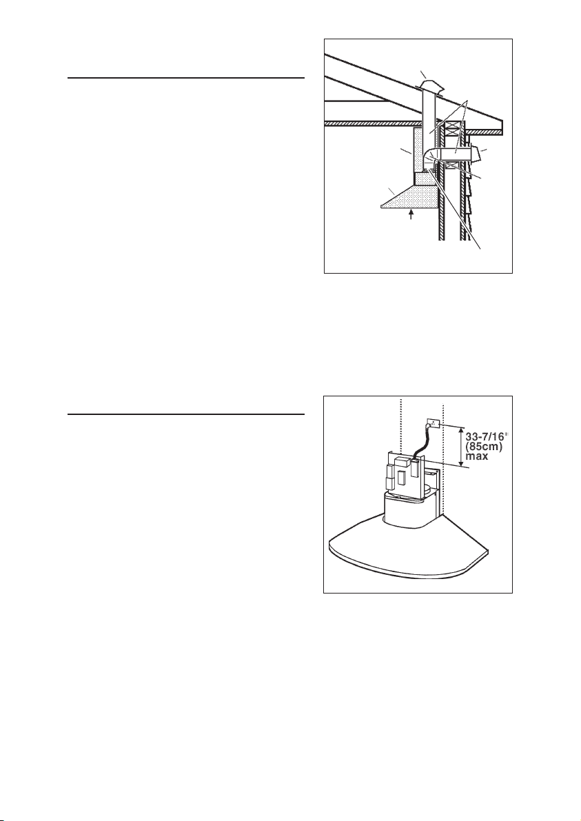
Set the electrical power supply within the space covered by the decorative flues.
Position the power socket at a maximum distance of 33-7/16” (85 cm) from where
the lead exits from the hood (see illustration alongside). Make sure this does not
interfere with the bracket fastening area or with the decorative flue (where the flue
touches the wall).
Fit the plug into the power socket.
- 5 -
INSTALL MOUNTING
BRACKET
1. Construct wood wall framing that is flush
with interior surface of wall studs.
Make sure:
a) the framing is centered over
installation location.
b) the height of the framing will allow the
mounting bracket to be secured to
the framing within the dimensions
shown.
After wall surface is finished, secure mount-
2.
ing bracket to framing using dimensions
shown.
NOTE:
- On 8’ ceilings, the hood distance above
cook top is :
minimum 24”, maximum 30” (for Ducted
Configuration).
minimum 24”, maximum 28” (for NonDucted Configuration).
- On 9’ ceilings, the hood distance above
cook top is :
minimum 26”, maximum 30” (the air vents
on the upper flue will be exposed after
installation).
FRAMING BEHIND DRYWALL
38-1/16” to 44-1/16” above
cooktop
38-1/16"= bottom of hood 24" above cooktop
44-1/16"= bottom of hood 30" above cooktop
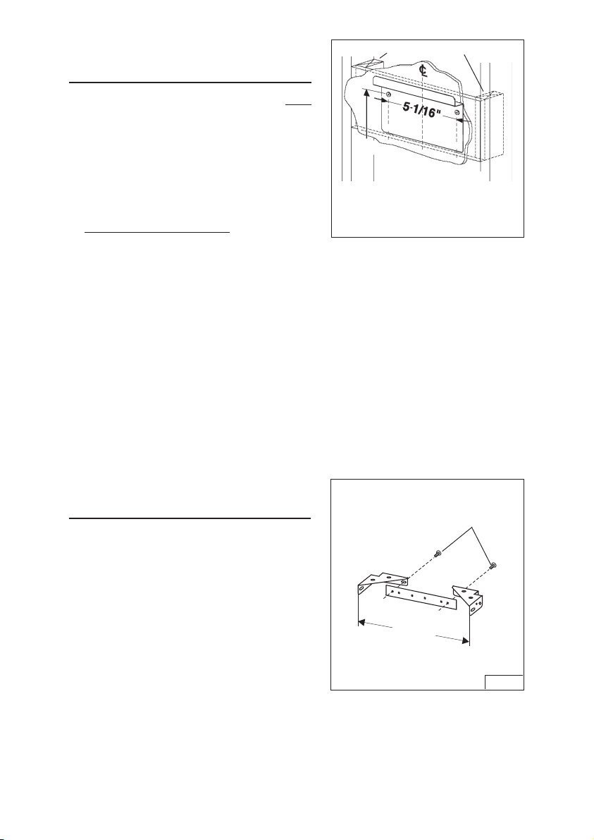
INSTALL FLUE MOUNTING
BRACKET
DUCTED AND NON-DUCTED
1. Assemble the flue mounting bracket,
adjusting outside width as shown. Fig.4
2. Carefully center the mounting bracket
directly over the range hood location.
3. Secure the bracket assembly to the ceiling
using (2) 4.8x38mm mounting screws
and drywall anchors. Make sure the
bracket is pushed into the corner, tight
against the wall and centered over the
hood.
- 6 -
FLUE MOUNTING
BRACKET
9 13/16”
(249.8mm)
3.9 x 5.7mm
FLAT HEAD
BRACKET SCREWS
FIG. 4

PREPARE THE HOOD
Note: On stainless steel hoods, carefully
remove the plastic protective film from all
exterior surfaces of the hood and
decorative flues, prior to final installation.
DUCTED CONFIGURATION
1.Install the discharge collar into the duct
connector of the range hood. Fig. 5
2. Attach an adequate length of 6” round steel
ducting to the range hood duct connector.
Fig. 5
3.Duct tape all joints to make them secure
and air tight.
4.Carefully place the lower decorative flue
into the recessed area of the range hood
top. Fig. 6
5.Carefully slide the upper decorative flue
down inside the lower flue. Fig. 6
Note: On 8” ceilings the air vents on the
upper flue are concealed by installing the
flue with air vents down.
On 9” ceilings, air vents on the upper flue
will be exposed after installation.
6”
DIAMETER
DUCT
DISCHARGE
COLLAR
DUCT
CONNECTOR
FIG. 5
UPPER
FLUE
LOWER
FLUE
UPPER
FLUE
VENTS
CONCEALED
- 7 -
UPPER
FLUE
LOWER
FLUE
UPPER
FLUE
VENTS
EXPOSED
FIG. 6
PREPARE THE HOOD
NON - DUCTED CONFIGURATION
Note: The following materials must be purchased separately for non-ducted
recirculation installations.
• Non - Ducted Recirculation Kit,
Model RRK51
• 1/16” diameter twist drill.
CAUTION: Do not use plastic or rigid metal ducting.
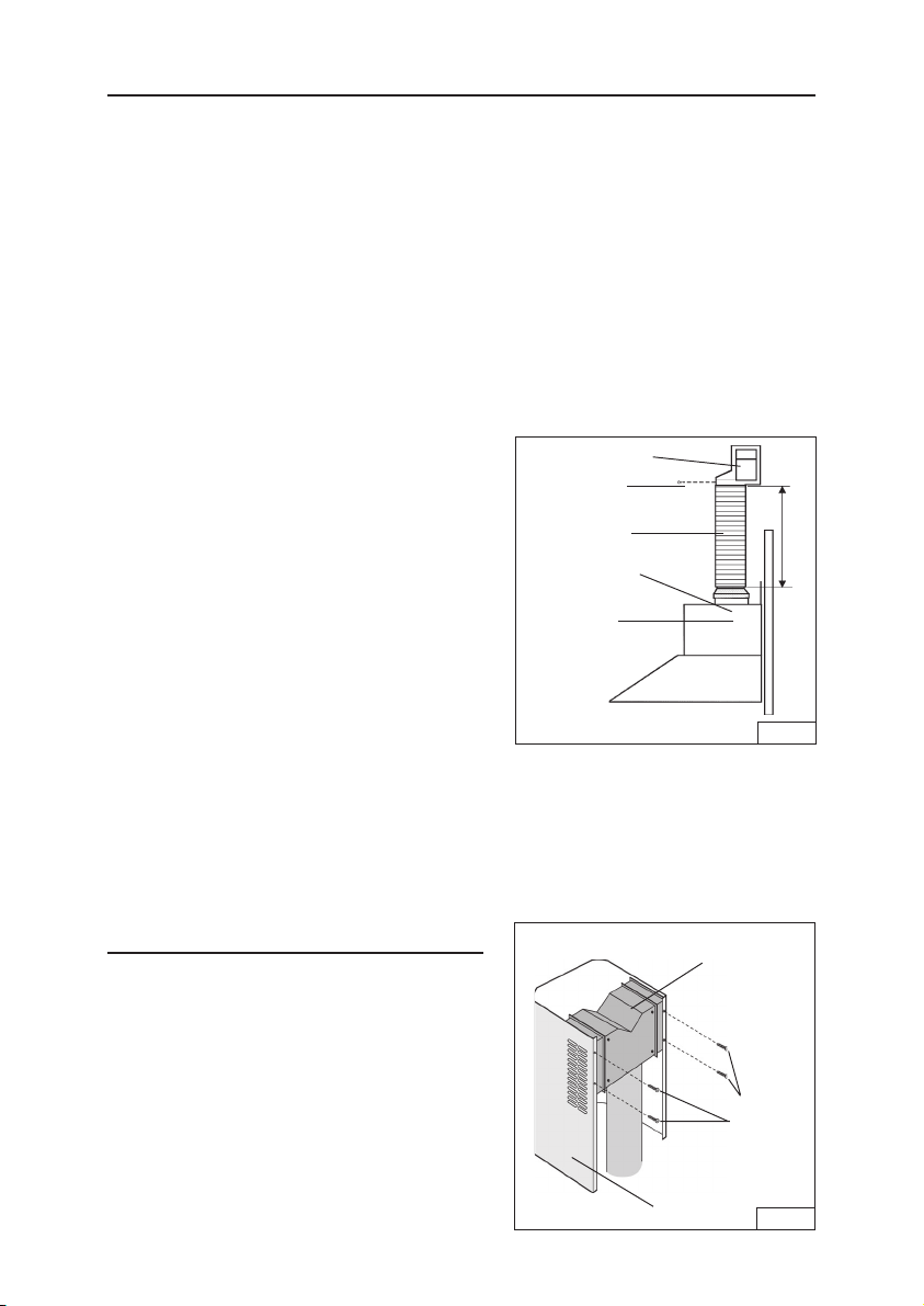
1.Discard discharge collar and damper supplied with the hood. Install the 5” to 6”
adapter supplied with the Non-Ducted
Recirculation Kit. Fig. 7.
2.Measure the distance “A”.
3.Attach aluminum flexible duct to the 5”
adapter. Tape all joints with duct tape.
Fig. 7.
4.Assemble the recirculation plenum to the
flexible duct. Fig. 7.
5.Drill three (3) 1/16” diameter equally
spaced holes through the duct and duct
connector of the recirculation plenum.
Fig.7.
PLENUM
(3) SCREWS
5” ALUMINUM
FLEX DUCT
5” 6” ADAPTER
BLOWER
COLLAR
A
FIG. 7
6.Secure duct to the plenum’s connector
with (3) sheet metal screws (not included).
Tape all joints with duct tape. Fig. 7.
PREPARE THE HOOD
NON - DUCTED CONFIGURATION, cont’d.
7. Carefully place the lower decorative flue
into the recessed area of the range hood
top. Fig. 6
8. Carefully slide the upper decorative flue
down inside the lower flue.
Note: air vents must be up. Fig. 6
9. Secure the recirculation plenum to the
upper flue with (4) flat head screws.
Fig. 8
- 8 -
UPPER
FLUE
PLENUM
4 FLAT
HEAD
SCREWS
FIG. 8

INSTALL THE
HOOD
LEVEL
SCREWS
(3.9x9.5mm)
MOUNTING
SCREWS
(4.8x38mm)
WALL FRAMING
Note: at least two people
will be required to mount
the hood.
MOUNTING
SCREWS
(4.8x38mm)
1. Raise the hood into its
mounting position.
2. Plug the power cord into
the electric wall
receptacle. Tuck
excess cord behind the
flue.
3. Align the rectangular
opening on the back of the hood with the
wall-mounting bracket. Gently lower the
hood until it securely engages the bracket.
Fig. 9
4. Level the hood with (2) screws
(3.9x9.5mm) and secure with (4)
mounting screws (4.8x38mm). Use
drywall anchors provided if wall studs or
framing are not available. Fig. 9
5. Secure the electrical system plate to the
range hood with (2) mounting screws
(3.9x9.5mm). Fig. 10
6. Raise the upper flue until its holes align
with holes in the flue mounting bracket
(located on ceiling). Fig. 11
7. Secure the flue with (2) mounting screws
(3.9x9.5mm). Fig. 11
3.9x9.5mm
SCREWS
3.9x9.5mm
MOUNTING SCREWS
MOUNTING
BRACKET
RECTANGULAR
CUTOUT
FIG. 9
ELECTRICAL
SYSTEM
PLATE
FIG.10
- 9 -
FIG.11

NON-DUCTED
RECIRCULATION FILTER
INSTALLATION
1. Purchase a charcoal filter (B03300488)
from your dealer.
2. Install the filter by pressing the 2 tabs on
the filter down into the special housing and
rotating upward.
CHARCOAL
FILTER
MAINTENANCE
Proper maintenance of the Range Hood will
assure proper performance of the unit.
Grease Filters
The grease filters should be cleaned fre-
quently. Use a warm detergent solution.
Grease filters are dishwasher safe.
Remove filter by pushing filter towards the
back of hood and rotating filter downward.
Charcoal Filter
The charcoal filter should be changed every
6 months. To remove the filter press inward
on the clamp and rotate the filter downward
until the 2 tabs can be removed from the
housing.
Hood Cleaning
Stainless steel is one of the easiest materials
to keep clean. Occasional care will help preserve its fine appearance.
Cleaning tips:
• Hot water with soap or detergent is all that is usually needed.
• Follow all cleaning by rinsing with clear water. Wipe dry with a clean, soft cloth to
avoid water marks.
• For discolorations or deposits that persist, use a non-scratching household cleanser
or stainless steel polishing powder with a little water and a soft cloth.
• For stubborn cases, use a plastic scouring pad or soft bristle brush together with
cleanser and water. Rub lightly in direction of polishing lines or "grain" of the
stainless finish. Avoid using too much pressure which may mar the surface.
• DO NOT allow deposits to remain for long periods of time.
• DO NOT use ordinary steel wool or steel brushes. Small bits of steel may adhere
to the surface causing rust.
• DO NOT allow salt solutions, disinfectants, bleaches, or cleaning compounds to
remain in contact with stainless steel for extended periods. Many of these compounds contain chemicals which may be harmful. Rinse with water after exposure and wipe dry with a clean cloth.
Painted surfaces should be cleaned with warm water and mild detergent only.
GREASE FILTERS
TABS
CLAMP
- 10 -

OPERATION
Controls
The hood is operated using the slide controls
under the bottom of the hood.
LIGHT
SWITCH
PILOT
LAMP
BLOWER
SWITCH
The light switch turns the lamps on and off.
The blower switch :makes it possible to
select the motor operating speed. Position 0:
motor off.
The pilot lamp lights up whenever the blower
is on.
HEAT SENTRY™
Your hood is equipped with a HEAT SENTRY™ thermostat. This thermostat is a
device that will turn on or speed up the blower if it senses excessive heat above
the cooking surface.
1) If blower is OFF - it turns blower ON to HIGH speed.
2) If blower is ON at a lower speed setting - it turns blower up to HIGH speed.
When the temperature level drops to normal, the blower will return to its original
setting.
WARNING
The HEAT SENTRY thermostat can start the blower even if the hood is turned
OFF. When this occurs, it is impossible to turn the blower OFF with its switch.
If you must stop the blower, do it from the main electrical panel.
HALOGEN BULBS
This range hood requires two halogen bulbs
(Type T3, 12Volt, 20 Watt Max, G-4 Base).
ALWAYS SWITCH OFF THE ELECTRICITY
SUPPLY BEFORE CARRYING OUT ANY
OPERATIONS ON THE APPLIANCE.
To change bulbs:
1. Loosen the ring nut by turning it
counterclockwise.
2. Remove the bulb by pulling sideward(DO
NOT ROTATE). CAUTION: BULB MAY BE
HOT!
3. Replace with Type T3, 12Volt, 20 Watt
Max, G-4 Base halogen bulb. Do not touch
replacement bulb with bare hands!
- 11 -
RING NUT

FUSE REPLACEMENT
SWITCH OFF THE ELECTRICITY SUPPLY.
Remove the decorative flue.
Open the fuse box.
Replace with the same type of fuse (5x20mm,
4A, 125V).
DECORATIVE
FLUE
FUSE
BOX
FUSE
WARRANTY
Broan-NuTone LLC (Broan-NuTone) warrants to the original consumer purchaser of Broan products that such products will
be free from defects in materials or workmanship for a period of one year from the date of original purchase. THERE ARE
NO OTHER WARRANTIES, EXPRESS OR IMPLIED, INCLUDING, BUT NOT LIMITED TO, IMPLIED WARRANTIES
OR MERCHANT ABILITY OR FITNESS FOR A PARTICULAR PURPOSE.
During this one-year period, Broan-NuTone will, at its option, repair or replace, without charge, any product or part which
is found to be defective under normal use and service.
THIS WARRANTY DOES NOT EXTEND TO FLUORESCENT LAMP STARTERS, TUBES, HALOGEN AND INCANDESCENT BULBS, FUSE, FILTERS, DUCTS, ROOF CAPS, WALL CAPS AND OTHER ACCESSORIES FOR DUCTING. This warranty does not cover (a) normal maintenance and service or (b) any products or parts which have been subject
to misuse, negligence, accident, improper maintenance or repair (other than by Broan-NuTone), faulty installation or installation contrary to recommended installation instructions.
The duration of any implied warranty is limited to the one-year period as specified for the express warranty. Some states
do not allow limitation on how long an implied warranty lasts, so the above limitation may not apply to you.
BROAN-NUTONE'S OBLIGATION TO REPAIR OR REPLACE, AT BROAN-NUTONE'S OPTION, SHALL BE THE
PURCHASER'S SOLE AND EXCLUSIVE REMEDY UNDER THIS WARRANTY. BROAN-NUTONE SHALL NOT BE
LIABLE FOR INCIDENTAL, CONSEQUENTIAL OR SPECIAL DAMAGES ARISING OUT OF OR IN CONNECTION
WITH PRODUCT USE OR PERFORMANCE. Some states do not allow the exclusion or limitation of incidental or consequential damages, so the above limitation or exclusion may not apply to you.
This warranty gives you specific legal rights, and you may also have other rights, which vary from state to state. This
warranty supersedes all prior warranties.
To qualify for warranty service, you must (a) notify Broan-NuTone at the address stated below or telephone number stated
below, (b) give the model number and part identification and (c) describe the nature of any defect in the product or part. At
the time of requesting warranty service, you must present evidence of the original purchase date.
In USA - BROAN, 926 West State St.,Hartford, WI 53027 www.broan.com (800-558-1711)
In CANADA - BROAN, 1140 Tristar Dr., Mississauga, ON LST 1H9 www.broan.ca (1-877-896-1119)
ONE YEAR LIMITED WARRANTY FOR BROAN PRODUCTS
- 12 -
 Loading...