

Page 1
INSTALLATION GUIDE
VB0185
1. T h e o n e a n d o n l y m a i n w a l l
2. These units have a new balancing
3. The terminal connectors for
IMPORTANT NOTES
control compatible with these
units is the VT9W wall control.
procedure, see Section 7.
these units are not in the
installation kit; they are already
mounted to their control board.
ERV200 ECM HRV200 ECM
ERV250 ECM HRV250 ECM
These products earned the ENERGY STAR® by meeting strict energy efficiency guidelines set by Natural
Resources Canada and the US EPA. They meet ENERGY STAR requirements only when used in Canada.
! !
RESIDENTIAL USE ONLY
READ AND SAVE THESE INSTRUCTIONS
Broan-NuTone LLC; Hartford, Wisconsin www.broan.com 800-543-3055
REGISTER YOUR PRODUCT ONLINE AT: www.broan.com/register
For additional information - visit www.broan.com
21992 rev. 01
Page 2
ABOUT THIS GUIDE
!
Because of the large amount of models covered in this publication, the illustrations are typical ones. Some details of your unit may be
slightly different than the ones shown.
Please take note that this guide uses the following symbols to emphasize particular information:
WARNING
Identifies an instruction which, if not followed, might cause serious personal injuries including possibility of death.
CAUTION
Denotes an instruction which, if not followed, may severely damage the unit and/or its components.
NOTE: Indicates supplementary information needed to fully complete an instruction.
ABOUT THESE UNITS
LIMITATION
For residential (domestic) installation only. Installation work and electrical wiring must be done by a qualified person(s) in accordance with
all applicable codes and standards, including fire-rated construction codes and standards.
WARNING
!
TO REDUCE THE RISK OF FIRE, ELECTRIC SHOCK, OR INJURY TO PERSON(S) OBSERVE THE FOLLOWING:
1. Use this unit only in the manner intended by the manufacturer. If you have questions, contact the manufacturer at the address or
telephone number listed in the warranty.
2. We recommend that your unit be inspected by a specialized technician once a year.
3. Before servicing or cleaning the unit, disconnect power cord from electrical outlet.
4. This unit is not designed to provide combustion and/or dilution air for fuel-burning appliances.
5. When cutting or drilling into wall or ceiling, do not damage electrical wiring and other hidden utilities.
6. Do not use the units with any solid-state speed control device other than the corresponding ones listed below:
UNIT MAIN CONTROL AUXILIARY CONTROL
ERV200 ECM, ERV250 ECM,
HRV200 ECM, HRV250 ECM
VTW9 EXCLUSIVELY VB60W
7. This unit must be grounded. The power supply cord has a 3-prong grounding plug for your personal safety. It must be plugged into a
mating 3-prong grounding receptacle, grounded in accordance with the national electrical code and local codes and ordinances. Do
not remove the ground prong. Do not use an extension cord.
8. Do not install in a cooking area or connect directly to any appliances.
9. Do not use to exhaust hazardous or explosive materials and vapors.
10. When performing installation, servicing or cleaning these units, it is recommended to wear safety glasses and gloves.
11. Due to the weight of the unit, two installers are recommended to perform installation.
12. When applicable local regulations comprise more restrictive installation and/or certification requirements, the aforementioned
requirements prevail on those of this document and the installer agrees to conform to these at his own expenses.
CAUTION
1. To avoid prematurate clogged filters, turn OFF the unit during construction or renovation.
2. Please read specification label on product for further information and requirements.
3. Be sure to duct air outdoors – Do not intake/exhaust air into spaces within walls or ceiling or into attics, crawl spaces, or garage.
4. Intended for residential installation only in accordance with the requirements of NFPA 90B (for a unit installed in USA).
5. Do not run any air ducts directly above or closer than 2 ft (0.61 m) to any furnace or its supply plenum, boiler, or other heat producing
appliance. If a duct has to be connected to the furnace return plenum, it must be connected not closer than 9’ 10” from this plenum
connection to the furnace.
6. The ductwork is intended to be installed in compliance with all applicable codes.
7. When leaving the house for a long period of time (more than two weeks), a responsible person should regularly check if the unit
operates adequately.
8. If the ductwork passes through an unconditioned space (e.g.: attic), the ducts must be insulated, and the unit must operate continuously
except when performing maintenance and/or repair. Also, the ambient temperature of the house should never drop below 65°F.
TECHNICAL SUPPORT
F
OR ASSISTANCE, CALL ON WEEKDAYS, 8:30 AM TO 5:00 PM (EASTERN STANDARD TIME): 1-800-543-3055.
NOTE: T
HIS PHONE NUMBER IS STRICTLY RESERVED FOR INSTALLERS USE ONLY. Do not call this number for ordering parts.
2
Page 3

TABLE OF CONTENTS
1. S ERVICE PARTS ...............................................................................................................................................................4-5
2. AIR DISTRIBUTION ...............................................................................................................................................................6
3. I
NSTALLATION .................................................................................................................................................................6-12
3.1 INSPECT THE CONTENT OF THE BOX ............................................................................................................................................... 6
3.2 LOCATING THE UNIT ..................................................................................................................................................................6-7
3.3 PLANNING OF THE DUCTWORK ....................................................................................................................................................... 8
3.4 DUCT SIZE ................................................................................................................................................................................ 8
3.5 INSTALLING THE DUCTWORK AND REGISTERS ............................................................................................................................... 8-10
3.6 CONNECTING THE DUCTS TO THE UNIT ..........................................................................................................................................11
3.7 INSTALLING TWO EXTERIOR HOODS .............................................................................................................................................. 12
3.8 CONNECTING THE DRAIN ............................................................................................................................................................ 12
4. CONTROLS ..................................................................................................................................................................13-16
4.1 UNITS BOOTING SEQUENCE ........................................................................................................................................................ 13
4.2 WALL CONTROL(S) ELECTRICAL CONNECTION ........................................................................................................................... 13-15
4.3 SETTING UNIT OPERATION IN THE REMAINING 40 MINUTES ON 20 MIN/H MODE AND SETTING UNIT DEFROST CYCLE TYPE
USING VT9W MAIN WALL CONTROL ............................................................................................................................................ 16
5. ELECTRICAL CONNECTION TO THE FURNACE ..........................................................................................................................17
6. WIRING DIAGRAM .............................................................................................................................................................. 18
7. B ALANCING THE UNIT ....................................................................................................................................................19-24
7.1 WHAT Y OU NEED TO BALANCE THE UNIT ...................................................................................................................................... 19
7.2 PRELIMINARY STAGES TO BALANCE THE UNIT.................................................................................................................................. 19
7.3 USING MAGNEHELIC GAUGES ....................................................................................................................................................... 19
7.4 BALANCING CHART AND PRESET SPEEDS TABLE ........................................................................................................................ 19-20
7.5 BALANCING PROCEDURE ........................................................................................................................................................ 21-24
8. TROUBLESHOOTING .......................................................................................................................................................25-27
3
Page 4
O
D
N
B
M
L
K
J
D
F
I
C
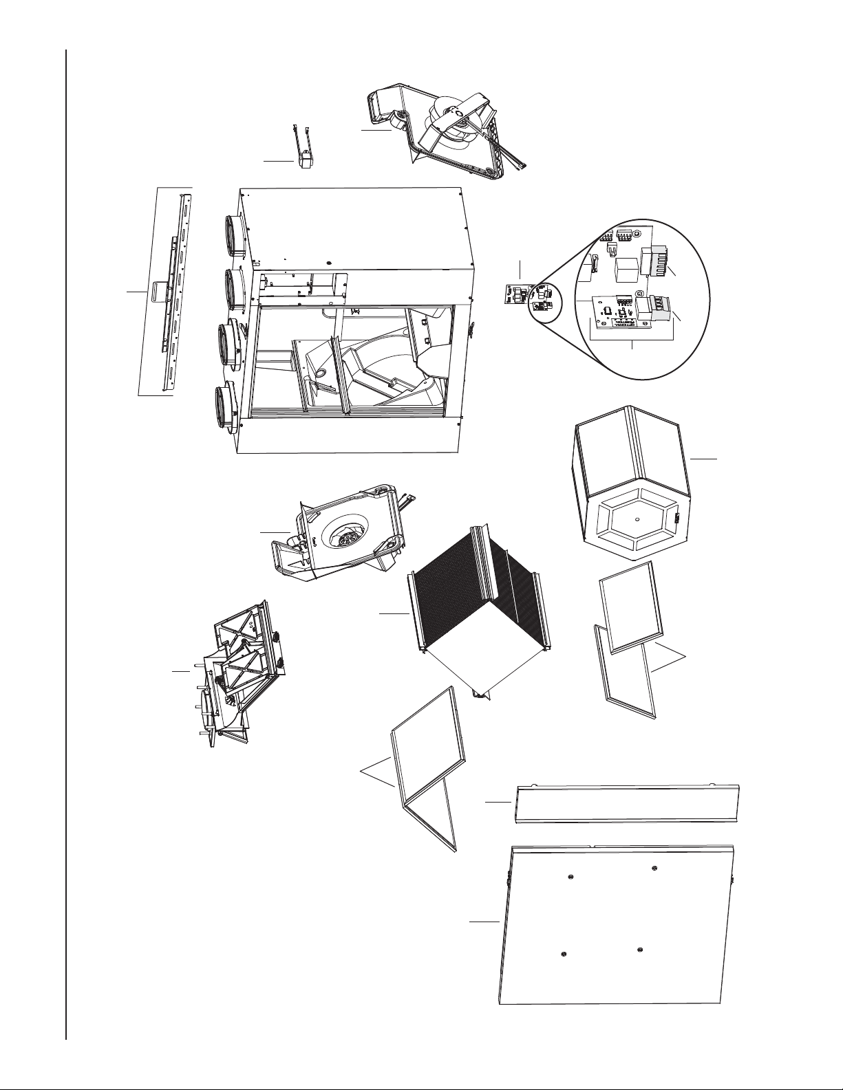
1. SERVICE PARTS
E
H
G
VL0071
4
Page 5
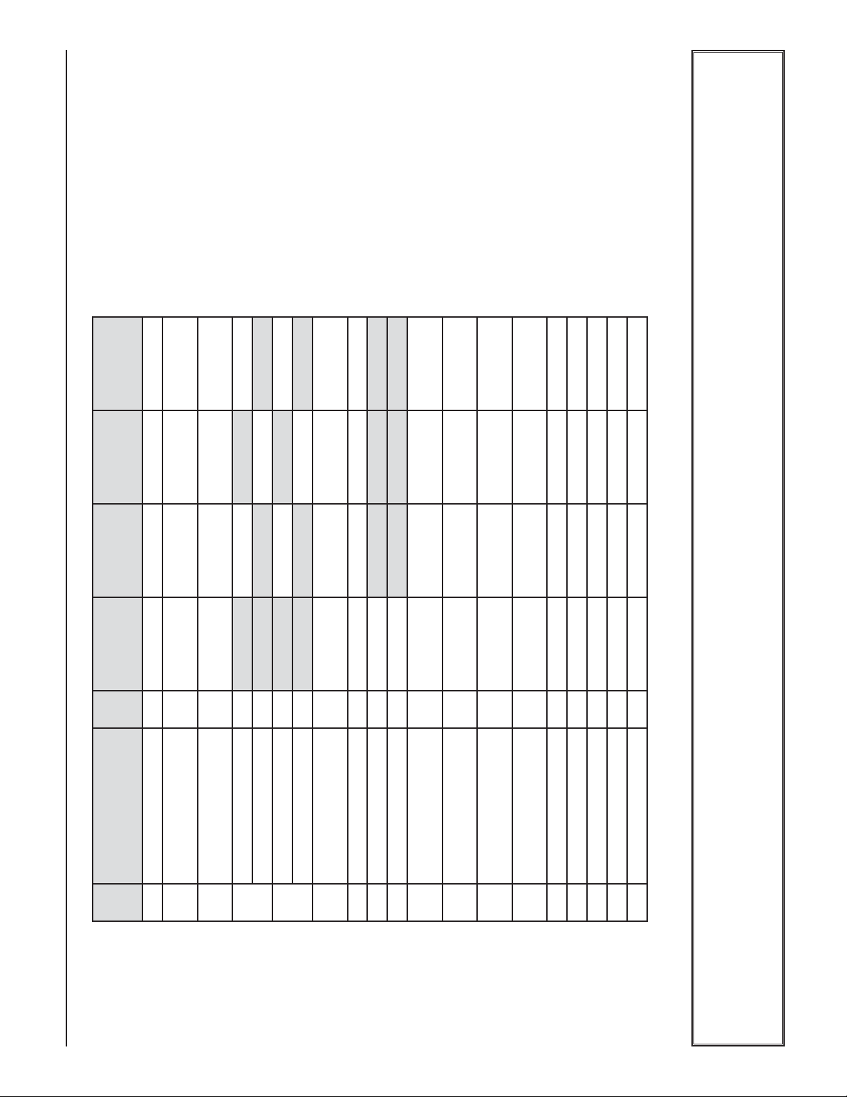
1 SV63420 SV63420 SV63420 SV63420
2 SV63421 SV63421 SV63421 SV63421
1 SV63569 SV63569 SV63569 SV63569
1 SV63437 SV63437 SV63437 SV63437
1 SV63434 SV63434 SV63434 SV63434
1 SV63435 SV63435 SV63435 SV63435
1 SV63436 SV63441 SV63442 SV63443
ORE FILTER (PAIR) 1 SV63426 SV63426
1BRACKET KIT 1 SV63419 SV63419 SV63419 SV63419
NO.DESCRIPTION QTY. ERV200 ECM HRV200 ECM ERV250 ECM HRV250 ECM
ORE FILTER (PAIR) 1 SV63433
AMPER SYSTEM ASSEMBLY
LOWER ASSEMBLY
(INCLUDING 2 PLASTIC SCREWS)
D
2
(INCLUDING 3 PLASTIC SCREWS)
B
3
HRV C
4
ERV C
EAT RECOVERY CORE 1 SV63422 SV63423
NERGY RECOVERY CORE 1 SV63425
E
H
5
OOR ASSEMBLY
D
6
IGHT PANEL 1 SV63565 SV63566 SV63567 SV63568
(INCLUDING NO. 16)
7R
ORE FILTER (PAIR) 1 SV63427
NERGY RECOVERY CORE 1 SV63424
8 ERV C
9E
1. SERVICE PARTS (CONT’D)
AUGHTER BOARD
D
5
10
(INCLUDING INO. 11)
ONNECTOR
(MAIN CONTROL)
PCB C
11
ONNECTOR
(AUXILIARY CONTROL)
PCB C
12
INCLUDING NOS. 10 &12)
PCB
(
13
ARM SIDE THERMISTOR KIT* 1 SV62481 SV62481 SV62481 SV62481
RANSFORMER 1 SV63438 SV63438 SV63438 SV63438
14 T
15 W
OOR MAGNETIC SWITCH* 1 SV19060 SV19060 SV19060 SV19060
16 D
ARDWARE KIT* 1 SV22488 SV22488 SV22488 SV22488
LASTIC SCREW (SET OF 6)* 1 SV63439 SV63439 SV63439 SV63439
17 P
18 H
* Not shown.
REPLACEMENT PARTS AND REPAIR
In order to ensure your ventilation unit remains in good working condition, you must use the Broan-Nutone LLC genuine replacement parts only. The Broan-NuTone LLC genuine
replacement parts are specially designed for each unit and are manufactured to comply with all the applicable certification standards and maintain a high standard of safety. Any
third party replacement part used may cause serious damage and drastically reduce the performance level of your unit, which will result in premature failing. Broan-NuTone LLC
recommends to contact a BRoan-NuTOne LLC certified service depot for all replacement parts and repairs.
Page 6
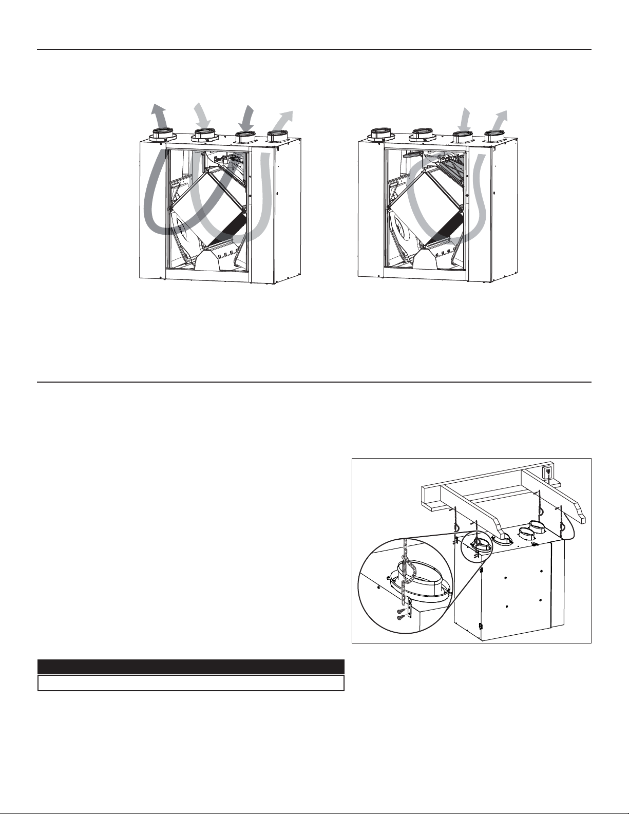
2. AIR DISTRIBUTION
STALE AIR
TO OUTDOORS
VF0063
NORMAL OPERATION DEFROST OR RECIRCULATION
FRESH AIR
FROM OUTDOORS
STALE AIR
FROM
BUILDING
FRESH AIR
BUILDING
TO
STALE AIR
FROM
BUILDING
FILTERED AIR
BUILDING
TO
3. INSTALLATION
3.1 INSPECT THE CONTENT OF THE BOX
Inspect the exterior of the unit for shipping damage. Ensure that there is no damage to the door, ports, power cord, etc.
3.2 LOCATING THE UNIT
Choose an appropriate location for the unit.
• Within an area of the house where the ambient temperature is kept
between 50°F and 104°F.
• Away from living areas (dining room, living room, bedroom), if possible.
• So as to provide easy access to the interior of the unit, for regular and
annual maintenance.
NOTE: There must be a 27” clearance in front of the unit to fully open
the door. In limited space, the door can be removed by lifting it
up, but there must be a 18” clearance in front of the unit to
remove the core.
• Close to an exterior wall, so as to limit the length of the insulated flexible
duct to and from the unit.
• Away from hot chimneys and other fire hazards.
• Allow for a power source (standard 3-prong grounding outlet).
• Close to a drain. If no drain is close by, use a pail to collect run-off.
The unit can be hung using provided 4 chains and springs (see at right) or
hung to the wall using provided brackets (see next page).
CAUTION
In every case, make sure the unit is level.
VD0378
UNIT HUNG BY CHAINS AND SPRINGS
6
Page 7
3. INSTALLATION (CONT’D)
!
OCATING THE UNIT (CONT’D)
3.2 L
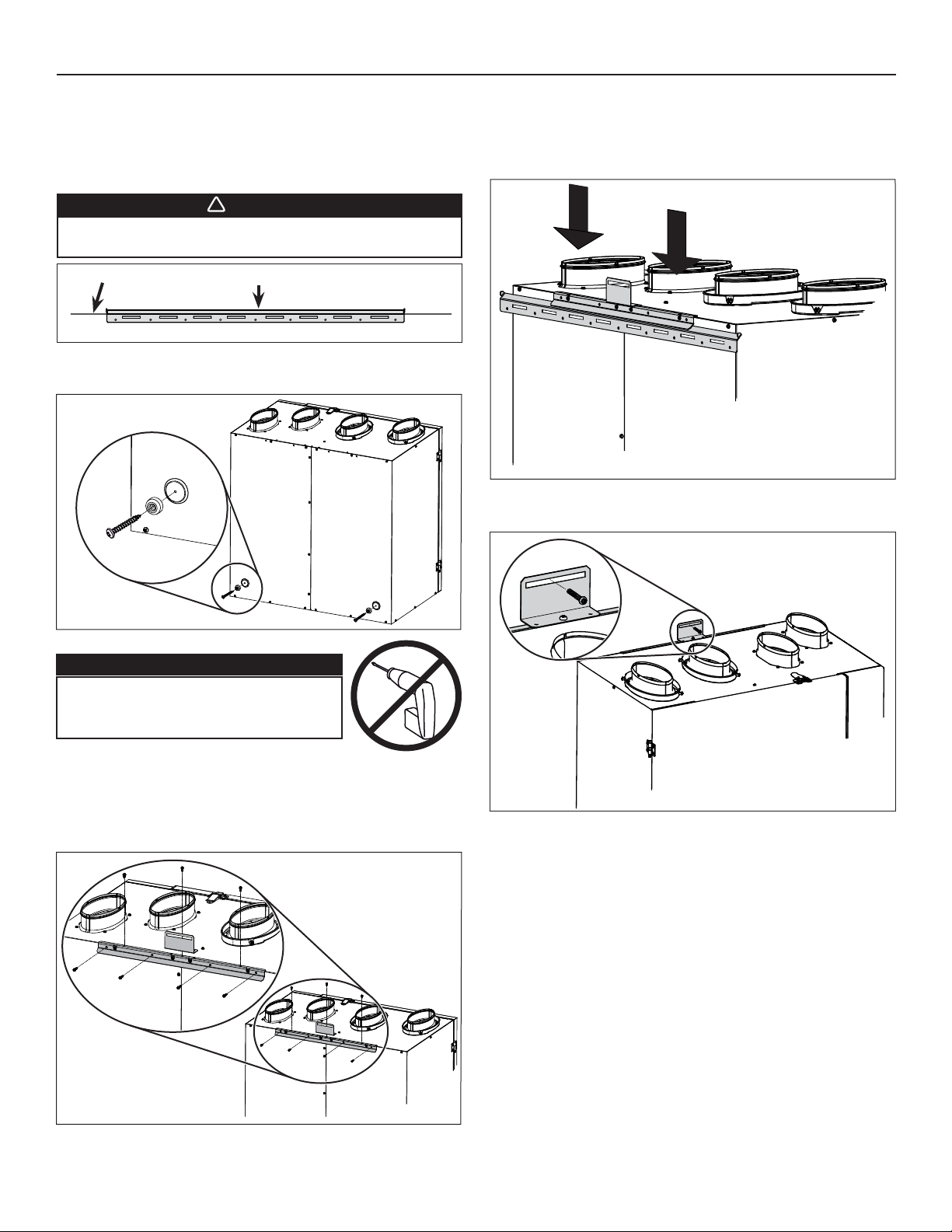
UNIT HUNG TO WALL BRACKET
Trace a level line on the wall; align the wall bracket (the longer
one) to the line and secure this bracket to the wall using 4 provided
screws (1½” long) and washers, if using the slots on bracket).
WARNING
Ensure the wall bracket is attached to all of the
available studs, not into the drywall alone.
LEVEL LINE WALL BRACKET
VD0379
Using 1½” long provided screws, assemble both spacers to left and
right back bottom corner of the unit.
Lift the unit and hang it to the wall bracket. Ensure the bracket
assembled on back of the unit rests on the wall bracket.
VO0271
Secure the unit to the wall using one 1½” long provided screw
through the small bracket.
VD0380
CAUTION
Never use an electric screwdriver or
drill to screw the brackets to the unit;
use a standard screwdriver.
VR0086
Using 3/8” long provided screws, mount the other bracket (A) to the
back of the unit; start with the 4 back screws, then 2 screws on top
left and right sides, then use the last center one to assemble the
last small bracket (B).
NOTE: These screws must be hand tightened.
B
A
VO0272
VD0392
7
Page 8
3. INSTALLATION (CONT’D)
!
3.3 PLANNING OF THE DUCTWORK
• Keep it simple. Plan for a minimum of bends and joints.
• Keep the length of insulated and non-insulated ducts to a minimum, because the length of the ductwork impacts directly the unit
airflow performances.
• Do not ventilate crawl spaces or cold rooms. Do not attempt to recover the exhaust air from a dryer or a range hood. This would cause
clogging of the filters and recovery module.
• If the house has two floors or more, be sure to plan for at least one exhaust register on the highest lived-in level.
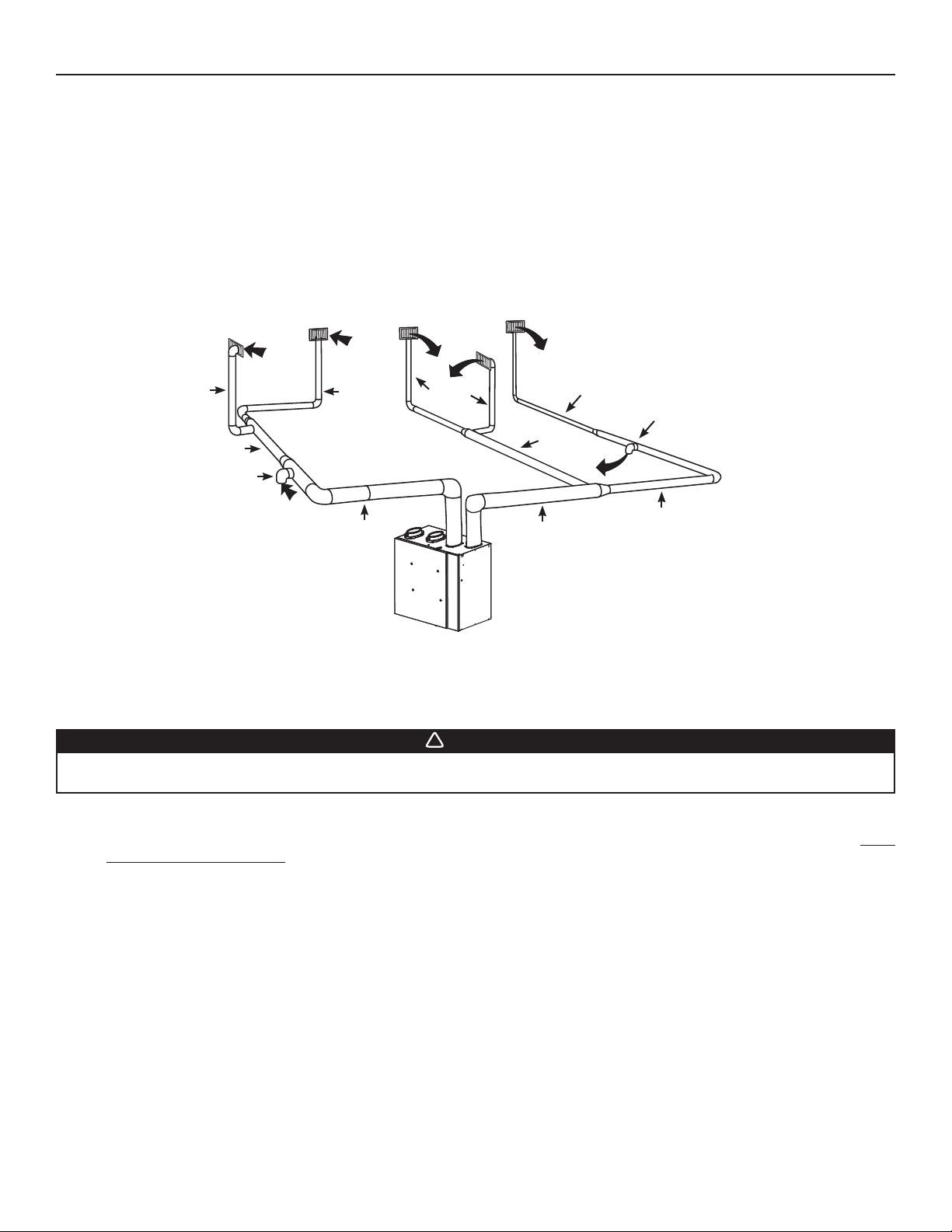
3.4 DUCT SIZE
To determine the appropriate duct size to be used, refer to the ASHRAE or HRAI HANDBOOK. Below is an example of a design
for a fully ducted system with a unit having a high speed performance of 160 cfm.
4" Ø, 47 CFM
5" Ø, 93 CFM
5" Ø, 67 CFM
4"
VI0019
4" 4"
4" Ø,
46 CFM
5"
6"
6" Ø, 160
4"
CFM
4"
4" Ø,
37 CFM
5"
4"
4" Ø, 24 CFM
5" Ø,
74 CFM
6"
6" Ø, 160 CFM
4"
5" Ø, 62 CFM
5"
5"
5" Ø, 86 CFM
3.5 INSTALLING THE DUCTWORK AND REGISTERS
3.5.1 FULLY DUCTED SYSTEM
WARNING
Never install a stale air exhaust register in a closed room where a combustion device operates, such as a gas
furnace, a gas water heater or a fireplace.
Stale air exhaust ductwork
• Install the stale air exhaust registers where the contaminants are produced: kitchen, living room, etc. Position the registers as far
from the stairway as possible and in such a way that the air circulates in all the lived-in spaces in the house.
• If a register is installed in the kitchen, it must be located at least 4 feet from the range.
• Install the registers 6 to 12 inches from the ceiling on an interior wall OR install them in the ceiling.
• If possible, measure the velocity of the air flowing through the registers. If the velocity is higher than 400 ft/min, then the register
type is too small. Replace with a larger one.
Fresh air distribution ductwork
• Install the fresh air distribution registers in bedrooms, dining rooms, living room and basement.
• Keep in mind that the fresh air registers must be located as far as possible from the stale air registers.
• Install the registers either in the ceiling or high on the walls with air flow directed towards the ceiling. (The cooler air will then cross
the upper part of the room and mix with room air, before descending to occupant’s level.)
• If a register must be floor installed, direct the airflow up the wall.
8
Page 9
3. INSTALLATION (CONT’D)
!
3.5 INSTALLING THE DUCTWORK AND REGISTERS (CONT’D)
3.5.2 CENTRAL DRAW POINT SYSTEM
Stale air exhaust ductwork
Same as for Fully Ducted System, described on point 3.5.1
WARNING
When performing duct connections, always use approved tools and materials. Respect all corresponding laws and
safety regulations. Please refer to your local building code.
CAUTION
When performing duct connections to the furnace supply duct, this duct must be sized to support the additional
airflow produced by the unit. Also, the use of metal duct is highly recommended.
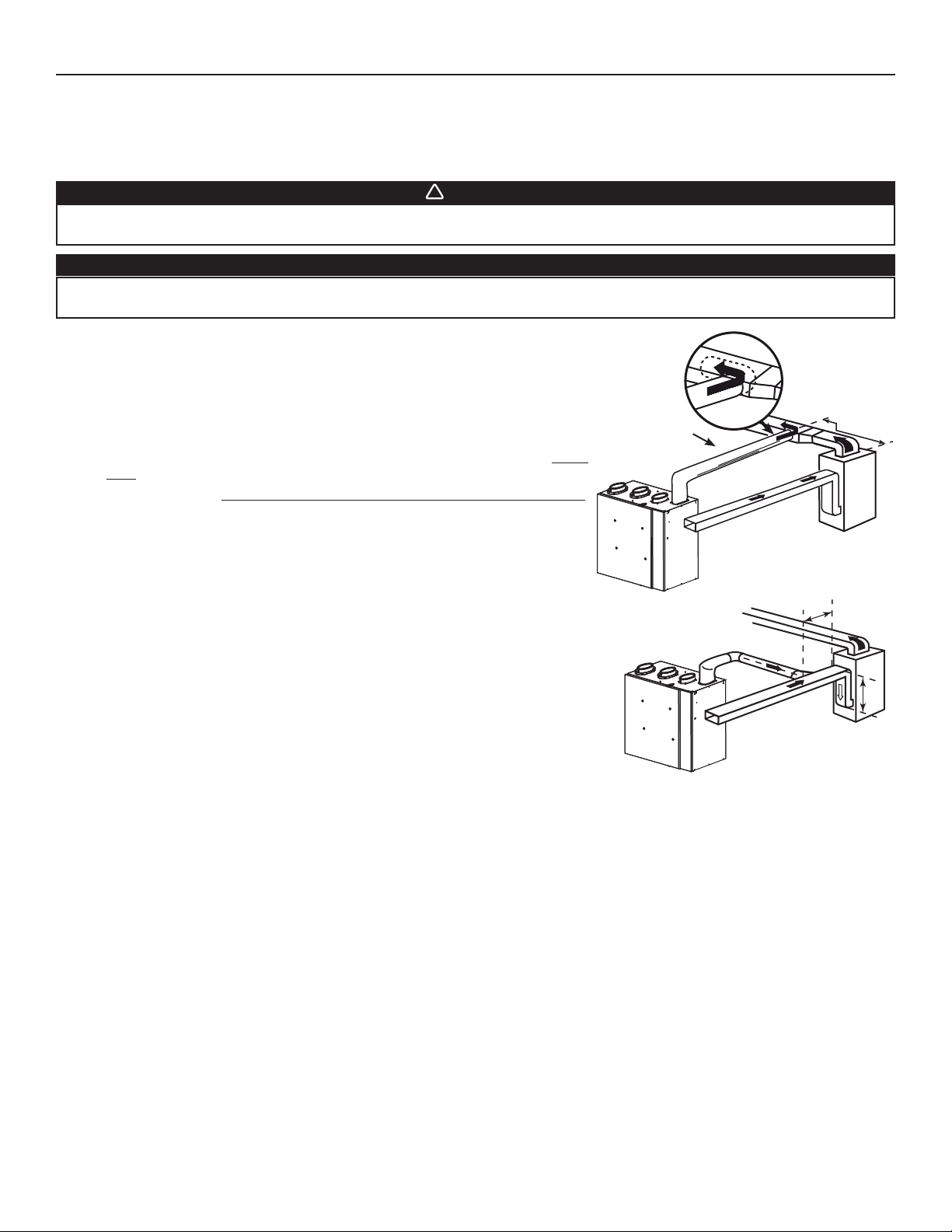
Fresh air distribution ductwork
• There are 2 methods for connecting the unit to the furnace/air handler:
Method 1: Supply side connection
• Cut an opening into the furnace supply duct at least 18 inches from the furnace/
air handler.
• Connect this opening to the Fresh air distribution port of the unit (use metal
duct, see figure at right).
• Make sure the unit duct forms an elbow inside the furnace/air handler ductwork.
• If desired, interlock (synchronize) the furnace/air handler blower operation (see
Section 5 ELECTRICAL CONNECTION TO THE FURNACE).
METAL DUCT
MINIMUM 18"
Method 2: Return side connection
• Cut an opening into the furnace return duct not less than 10 feet from the furnace/
air handler (A+B).
• Connect this opening to the Fresh air distribution port of the unit (see figure at
right).
NOTE: For Method 2, it is not essential that the furnace/air handler runs when the
unit is operation, but we recommend it. If desired, interlock (synchronize)
the furnace/air handler blower operation (see Section 5 ELECTRICAL
CONNECTION TO THE FURNACE).
VJ0128
A
B
A+B = NOT LESS
THAN 10’
VJ0129
9
Page 10

3. INSTALLATION (CONT’D)
!
3.5 INSTALLING THE DUCTWORK AND REGISTERS (CONT’D)
3.5.3 SIMPLIFIED INSTALLATION
WARNING
When performing duct connections, always use approved tools and materials. Respect all corresponding laws and
safety regulations. Please refer to your local building code.
CAUTION
When performing duct connections to the furnace supply duct (Method 1), this duct must be sized to support the
additional airflow produced by the unit. Also, the use of metal duct is highly recommended. For a Return-return
installation, the furnace blower must be in operation when the unit is in operation.
There are 2 methods for connecting the unit to the furnace/air handler:
Method 1: Supply-return connection Method 2: Return-return
A
MINIMUM 18"
METAL DUCT
B
MINIMUM 3'
B
VJ0131
A+B = NOT LESS
THAN 10’
A
A+B = NOT LESS
VJ0130
THAN 10’
Stale air intake
• Cut an opening into the furnace/air handler return duct not less than 10 feet from the furnace/air handler (A+B).
• Connect this opening to the Exhaust air from building port of the unit.
Fresh air distribution
• Same instructions as for Method 1 or Method 2, Section 3.5.2.
For Method 2 (Return-return), make sure there is a distance of at least 3 feet between the 2 connections to the furnace/air handler.
CAUTION
If using Method 2, make sure the furnace/air handler blower operation is synchronized with the unit operation!
See Section 5.
NOTE: For Method 1, it is not essential to synchronize the furnace blower operation with the unit operation, but we recommend it.
10
Page 11
3. INSTALLATION (CONT’D)
3.6 CONNECTING THE DUCTS TO THE UNIT
NOTE: All unit ports are were created to be connected to ducts having a minimum of 6” diameter, but if need be, they can be connected
to bigger sized ducts by using an appropriate transition (e.g.: 6” diameter to 7” diameter transition).
Insulated flexible ducts
Use the following procedure to connect the insulated flexible ducts to the ports of the unit (Exhaust air to outdoors and Fresh air
from outdoors ports).
CAUTION
If ducts have to go through an unconditioned space (e.g.: attic), always use insulated ducts.
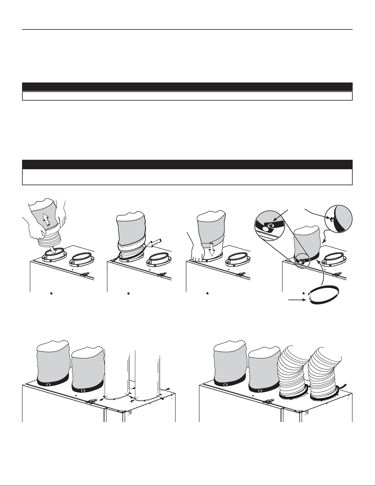
Pull back the insulation to expose the flexible duct.
Attach the flexible duct to the port using tie wrap.
Pull the insulation over the joint and tuck in between the inner and outer rings of the double collar.
Pull down the vapor barrier (shaded part in illustrations below) over the outer ring to cover it completely. Fasten in place the vapor
barrier using the port strap (included in unit parts bag). To do so, insert one collar pin through vapor barrier and first strap hole,
then insert the other collar pin through vapor barrier and center strap hole and close the loop by inserting the first collar pin in the
last strap hole.
CAUTION
Make sure the vapor barrier on the insulated ducts does not tear during installation to avoid condensation within
the ducts.
12 3 4
VJ0132
Non-insulated rigid ducts
Use metal screws and duct tape to connect the rigid ducts to the
unit ports.
COLLAR PINS
STRAP
Non-insulated flexible ducts
Use tie wraps to connect the flexible ducts to the unit ports.
VJ0133
11
Page 12
3. INSTALLATION (CONT’D)
!
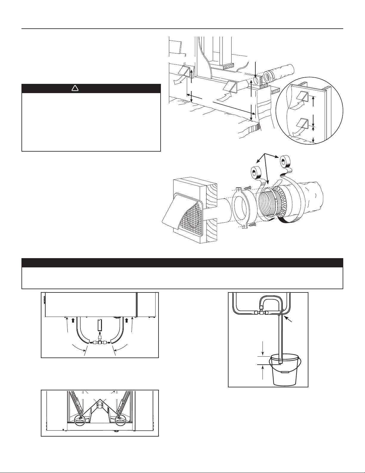
3.7 INSTALLING TWO EXTERIOR HOODS
Choose an appropriate location to install the exterior hoods:
• There must be a minimum distance of 6 feet between
the hoods to avoid cross-contamination.
• There must be a minimum distance of 18 inches from
the ground.
EXHAUST HOOD
INTAKE HOOD
6" Ø
PTIONAL DUCT
O
LOCATION
WARNING
Make sure the intake hood is at least 6 feet away
from any of the following:
• Dryer exhaust, high efficiency furnace vent,
central vacuum vent
• Gas meter exhaust, gas barbecue-grill
• Any exhaust from a combustion source
• Garbage bin and any other source of
contamination.
Refer to figure at right for connecting insulated ducts to the
exterior hoods. An “Anti-gust intake hood’’ should be installed
in regions where a lot of snow is expected to fall.
3.8 CONNECTING THE DRAIN
VD0028
18"
6'
18"
6'
18"
TAPE AND DUCT TIE
CAUTION
A drain tubing (included) must be installed for all HRV units. For ERV units, it is not required, however, it is
recommended for climates where the outdoor temperature typically remains below -13°F, (over a 24-hour period)
for several days in a row, combined with an indoor humidity of 40% or higher.
TIE WRAP
16"
(406 mm)
VO0273A
16"
(406 mm)
± 1”
Cut 2 sections of the plastic tube, at least 16” long, and attach them
to each inner drain fitting, located under the unit.
Join both short sections to the “T” junction and main tube as shown.
DRAIN PLUG LOCATIONS
VD0387
NOTE: For ERV units installed in cold climate, remove both drain
plugs inside the unit prior to install tubing.
Make a water trap loop in the tube to prevent the unit from
drawing unpleasant odors from the drain source. Make sure this
loop is located OVER the “T” as shown. Run the tube to the floor
drain or to an alternative drain pipe or pail.
IMPORTANT
If using a pail to collect water, locate the tube end approximately
1” from the top of the pail in order to prevent water from being
drawn back up into the unit.
12
VD0337A
Page 13
4. CONTROLS
!
4.1 UNIT BOOTING SEQUENCE
The unit booting sequence is similar to a personnal computer boot sequence. Each time the unit is plugged after being unplugged, or after
a power failure, the unit will perform a 30-second booting sequence before starting to operate.
During the booting sequence, the unit is checking and resetting the motorized damper position.
Once the motorized damper position completely set, the booting sequence is done.
NOTE: No command will be taken until the unit is fully booted.
4.2 WALL CONTROL(S) ELECTRICAL CONNECTION
WARNING
The VT9W wall control is the only main wall control compatible to your unit. Never attempt to install another wall
control model. Always disconnect the unit before making any connections. Failure to disconnect power could
result in electric shock or damage to the wall control or electronic module inside the unit.
CAUTION
Failure to comply with the following can cause erratic operation of the unit and/or the wall control:
Never install more than one VT9W main wall control per unit. Make sure that the wires do not short-circuit between
themselves or by touching any other components on the wall control. Avoid poor wiring connections. To reduce
electrical interference (noise) potential, do not run wall control wiring next to control contactors or near light
dimming circuits, electrical motors, dwelling/building power or lighting wiring, or power distribution panel.
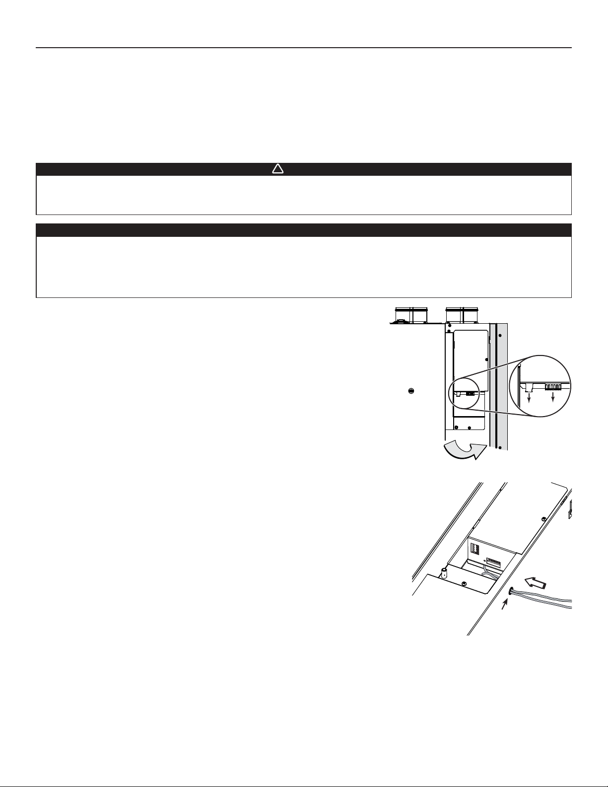
Unplug the unit from power source. Open the side panel to access terminal blocks
(A is the one for main control connection only and B is the one for auxiliary controls). Pull
out from the unit board the needed connector(s).
VE0351
Run the end of the control wire(s) through the grommet located on the unit wall. Refer to
illustration at right (side panel removed to ease understanding).
GROMMET
B
A
13
Page 14
4. CONTROLS (CONT’D)
4.2 WALL CONTROL(S) ELECTRICAL CONNECTION (CONT’D)
4.2.1 TERMINAL BLOCK(S) CONNECTION
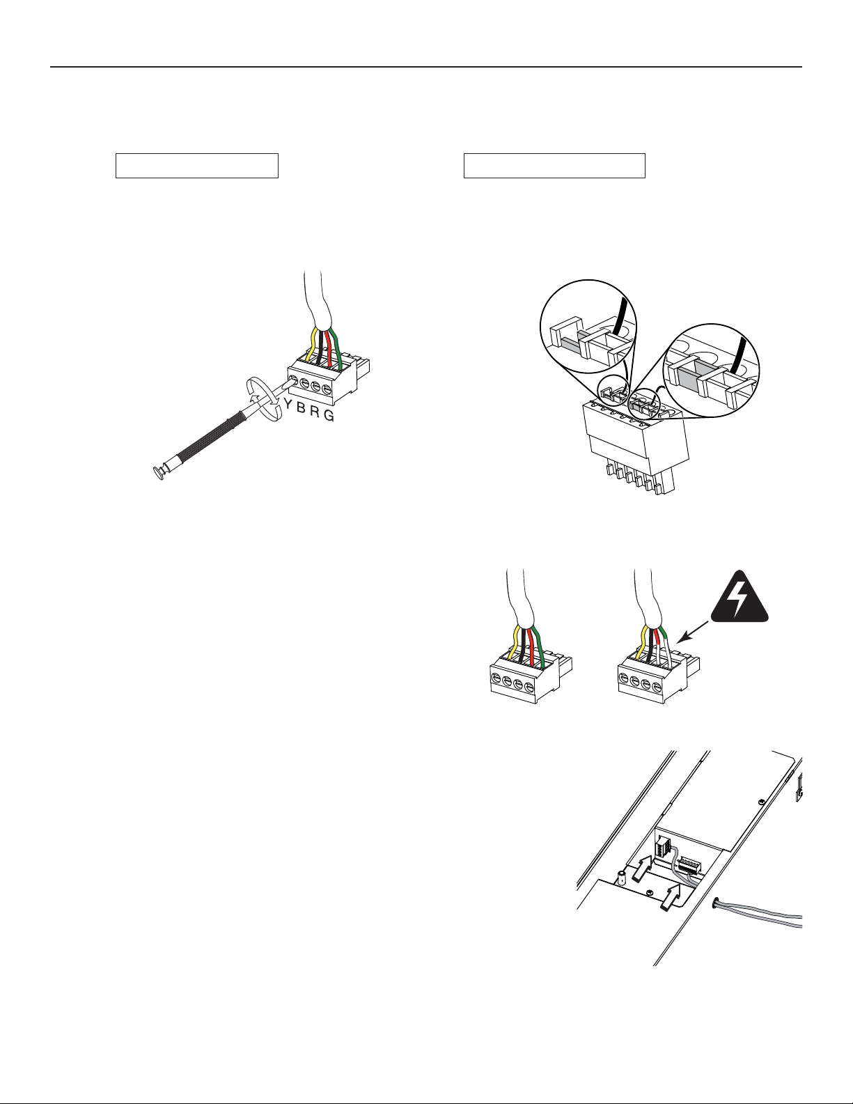
MAIN CONTROL TERMINAL BLOCK
Strip the end of the main control cable to access the 4 wires.
Strip the end of each wire. Using a small flat blade screwdriver,
connect each wire to its corresponding terminal, by referring
on the sticker affixed on the unit: YELLOW wire to “Y”, BLACK
wire to “B”, RED wire to “R” and GREEN wire to “G”.
VE0352
AUXILIARY CONTROL TERMINAL BLOCK
Strip the end of the auxiliary control cable to access the wires.
Strip the end of 3 wires. Check if all wires are correctly inserted in
their corresponding holes in the terminal block. (A wire is correctly
inserted when its orange receptacle is lower than another one
without wire. On illustration below, wire A is correctly inserted,
but wire B is not.)
A
B
VE0353
RIGHT WRONG
When stripping the wires, ensure to remove only the necessary
lenght of sheat in order to prevent short circuits.
VE0354
Once the terminal block(s) connections have been made, reinstall it (them)
on the unit PC board. Refer to illustration at right (side panel removed to ease
understanding). Close the side panel.
NOTE: For information about the operation of the wall controls, refer to their
installation sheet.
VE0355
14
Page 15
4. CONTROLS (CONT’D)
4.2 WALL CONTROL(S) ELECTRICAL CONNECTION (CONT’D)
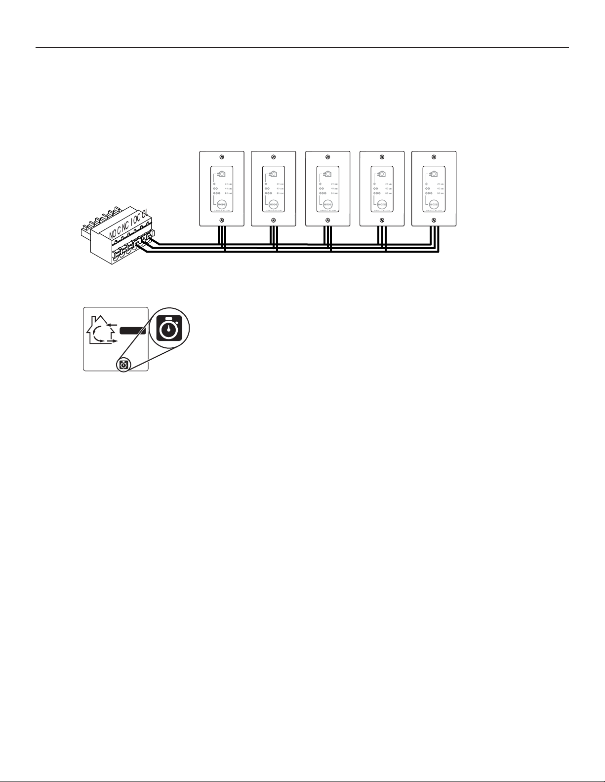
4.2.2 E
LECTRICAL CONNECTION TO VB60W OPTIONAL AUXILIARY CONTROL(S)
Up to five (5) VB60W auxiliary controls can be installed.
VE0349
When used, the VB60W activation will override the main control operation, as well as the unit
CONT
defrost cycle. On example shown on the left, the unit was in CONT mode when the auxiliary
control was activated; so the actual operation mode stays on VT9W main wall control screen,
but the chronometer icon appears as long as the VB60W is activated.
NOTE: In colder regions, the chronometer icon may stay after the end of the VB60W cycle,
due to defrost cycle.
15
Page 16
4. CONTROLS (CONT’D)
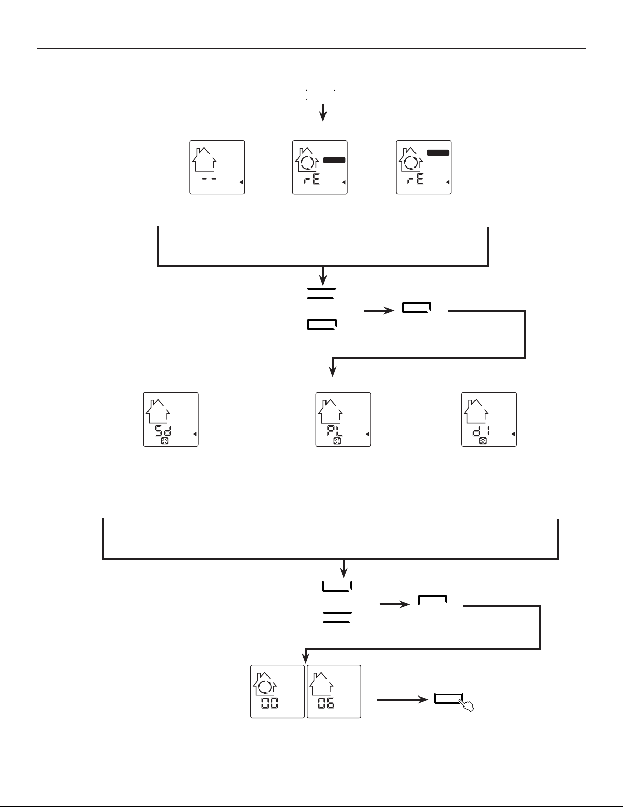
4.3 SETTING UNIT OPERATION IN THE REMAINING 40 MINUTES ON 20 MIN/H MODE AND SETTING UNIT DEFROST CYCLE TYPE
USING VT9W MAIN WALL CONTROL
Press and hold the
MODE key for 3 seconds.
The LCD screen will show one of these configurations:
MODE
3 sec.
OR
Two lines are flashing
to show Standby
(default configuration
setting).
Use MODE or TURBO key to
see all 3 configurations.
The LCD screen will show one of these defrost cycle types:
Recirculation arrows
flashes and CONT
label appears to show
RECIRCULATION on
OR
CONT
are turning, rE
low speed.
MODE
!
OR
TURBO
TURBO
OR
Recirculation arrows
are turning, rE
flashes and TURBO
label appears to show
RECIRCULATION on
high speed.
% HUM
Press % HUM key to accept chosen
configuration and go to setting defrost
cycle type.
OR
Sd (Standard)
(factory defrost cycle setting).
When needed, the unit will
perform defrost cycle on high
speed.
NOTE: This is the defrost type
used for the data published by
HVI and ENERGY STAR®.
Use MODE or TURBO key
to see all 3 defrost cycle type.
LCD screen alternates between the
house with circled arrows and the house
without arrow. The numbers under the
house are the software version number.
PL (Plus)
Use this cycle in cold region
(outdoor temperature -17°F and
lower). When needed, the unit
will perform defrost cycle on
high speed on a longer period
of time.
MODE
!
OR
TURBO
16
Press % HUM key to accept
chosen defrost cycle type and
go to software version display
dI (Discretion)
When needed, the defrost cycle
will be performed on the same
speed than the unit ventilation
speed. (e.g.: if the unit is set on
TURBO, the defrost cycle will
be done on high speed, and
if the unit is set on CONT, the
defrost cycle will be done on
low speed.
% HUM
% HUM
Press % HUM key OR
wait 10 seconds to exit
user setting menu.
Page 17
5. ELECTRICAL CONNECTION TO THE FURNACE
!
WARNING
Never connect a 120-volt AC circuit to the terminals of the furnace interlock (standard wiring). Only use the low
voltage class 2 circuit of the furnace blower control.
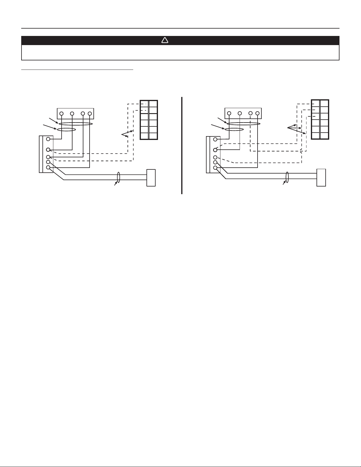
For a furnace connected to a cooling system:
On some older thermostats, energizing the “R” and “G” terminals at the furnace has the effect of energizing “Y” at the thermostat and
thereby turning on the cooling system. If you identify this type of thermostat, you must use the
STANDARD FURNACE INTERLOCK WIRING ALTERNATE FURNACE INTERLOCK WIRING
UNIT TERMINAL CONNECTOR
NO C NC I OC OL
ALTERNATE FURNACE INTERLOCK WIRING.
NO C NC I OC OL
UNIT TERMINAL CONNECTOR
4 WIRES
2 WIRES
heating only
FURNACE
24-VOLT
TERMINAL BLOCK
VE0350A
WRGY
W
R
G
C
Y
Y
THERMOSTAT
TERMINALS
LOW VOLTAGE
CLASS 2
2 WIRES
COOLING SYSTEM
4 WIRES
2 WIRES
heating only
W
R
G
C
Y
FURNACE
24-VOLT
TERMINAL BLOCK
WRGY
R
Y
THERMOSTAT
TERMINAL
LOW VOLTAGE
CLASS 2
NO
NC
C
2 WIRES
COOLING SYSTEM
17
Page 18

6. WIRING DIAGRAM
r
!
WARNING
• Risk of electric shocks. Before performing any maintenance or servicing, always disconnect the unit from its power source.
• This product is equipped with an overload protection (fuse). A blown fuse indicates an overload or a short-circuit situation.
If the fuse blows, unplug the product and check the polarity and voltage output from the outlet. Replace the fuse as per the
servicing instructions (refer to wiring diagram for proper fuse rating) and verify the product. If the replaced fuse blows, it may
be a short-circuit and the product must be discarded or returned to an authorized service center for examination and/or repair.
From
supply motor
From
Neutral
120V, 60Hz
LOGIC DIAGRAM
Line
120 V, 60Hz
J10-1J10-2
321
HI MED
J5-2
Exhaust
fan motor
J5-1
A1
K1
JU1
K2
F1
J9-2
J9-1
B
J5-3
J9-3
to A1-J17
J7-2
J9-4
J7-1
Supply
fan motor
K3
J4-1
J4-2
J4-3
to A1-J15
J6-2
J6-1
A2
J2-5
J12-5
J2-4
J12-4
Damper motor
J2-3
J12-3
K4
J3-2
J2-2
J12-2
J8-1
120 V
J3-1
J2-1
J12-1
J8-2
24 V
J8-4
class 2
Door interlock switch
J11-2
J8-5
9.5 V
class 2
J11-1
neutral
Furnace
blower
interlock
J14-3
J14-1
K5
K2K4K5
(optional; see
J14-2
K1
notes 3 & 5)
J15
12345
K3
nc
J17
12345
exhaust moto
nc
CPU
J16
J2
A3
Override
switch
(optional; see
J14-4
J14-5
notes 3 & 4)
J14-6
J3-4
J3-3
J3-2
J3-1
Field wiring
remote control
(see notes 3 & 4)
WIRING DIAGRAM
B
Damper motor
DAMPER
A2
1234512
J3
12
B
M3
ELECTRONIC ASSEMBLY
J1
J2
S1
reed switch)
Door interlock switch
(magnetically actuated
Defrost
temperature sensor
Class 2
to A1-J12
W W
T1
120 V
B
R1
t˚
low voltage
24 V
class 2
factory wiring
9.5 V
From
exhaust motor
From
supply motor
class 2
W
neutral
control cable
control cable
BR
BR
Y
Y
Override
R2
Thermistor
t˚
J17
nc
W
R
BL
Y
12345
nc
W
R
BL
Y
12345
J15
12
J11
12345
J8
123
J5
BL
BR
G
Power cable
switch
notes 3 & 4)
(optional; see
65432
J20
12345
to
A2-J2
123
MED HI
JU1
M1
Exhaust fan motor
18
J14-1: NO
Furnace blower interlock
J14
1
2
1
J13
J12
A1
12
1234
J9
See note 1
123
Control cable
W
R
BL
Y
to A1-J17
Power cable
J14-2: COM
J14-3: nc
(optional; see notes 3 & 5)
BDM
J2
J16
ASSEMBLY
ELECTRONIC
W
B
J10
F1
J4
BL
BR
M2
Supply fan motor
G
Field wiring
remote control
(see notes 3 & 4)
Y
R
B
G
J3
432
1
A3
W1
120 V, 60 Hz
Control cable
W
R
BL
Y
to A1-J15
Line voltage factory wiring
Class 2 low voltage factory wiring
Class 2 low voltage field wiring
G
Critical characteristic.
WHITE
COLOR CODE
BBLACK
BL BLUE
BR BROWN
GGREEN
RRED
Y YELLOW
W
nc no connection
NOTES
codes, ordinances and regulations.
be replaced, use the same equivalent wire.
(3A, 3AG Type).
1. Use specified UL listed/CSA Certified line fuse
2. If any of the original wire, as supplied, must
3. Field wiring must comply with applicable
4. Remote controls (class 2 circuit) available,
see instruction manual.
5. Furnace fan circuit must be class 2 circuit only.
VE0346A
Page 19

7. BALANCING THE UNIT
7.1 WHAT YOU NEED TO BALANCE THE UNIT
• One VT9W main wall control close to the unit.
• A magnehelic gauge capable of measuring 0 to 0.5 inch of water (0 to 125 Pa) and 2 plastic
tubes.
• The balancing chart of the unit.
VP0009
7.2 PRELIMINARY STAGES TO BALANCE THE UNIT
• Seal all the unit ductwork with tape. Close all windows and doors.
• Turn off all exhaust devices such as range hood, dryer and bathroom fans.
• Make sure all filters are clean (if it is not the first time the unit is balanced).
NOTE: Make sure that the furnace/air handler blower is ON if the installation is in any way connected to the ductwork of the cold air
return. If not, leave furnace/air handler blower OFF.
7.3 USING MAGNEHELIC GAUGES
HIGH
1. Place the magnehelic gauge on a level surface and adjust it to zero.
2. According to the airflow to be measured, connect tubing from gauge
to STALE air flow or FRESH air flow pressure taps (see illustration at
right).
Be sure to connect the tubes to their appropriate high/low fittings. If
the gauge drops below zero, reverse the tubing connections.
VP0027A
7.4 BALANCING CHART AND PRESET SPEEDS TABLE
The unit balancing chart and the unit preset speed table are affixed on the unit, behind the
right panel (circled area on illustration at right).
LOW
FRESH AIR FLOW
HIGH
LOW
STALE AIR FLOW
19
VD0388
Page 20

7. BALANCING THE UNIT (CONT’D)
7.4 BALANCING CHART AND PRESET SPEEDS TABLE (CONT’D)
Use the balancing chart to convert pressure (in. w.g.) values read from magnehelic gauge to airflow (CFM) values. While balancing,
the VT9W wall control screen shows which pressure taps have to be used. See example below.
UNIT BALANCING CHART
Plug magnehelic gauge
tubing to STALE airflow.
Plug magnehelic gauge
tubing to FRESH airflow.
NOTE: The unit is considered balanced even if there is a difference of ± 10 CFM (or ± 5 L/s or 17 m³/h) between the two airflows.
The special design of these units, combined with the VT9W main wall control, offer many preset speeds ranges according
to the unit models.
See preset speeds table example below.
PRESET SPEEDS TABLE
FLOW FRESH STALE
CFM IN. W.G. IN. W.G.
120 0.71 0.73
125 0.67 0.70
130 0.63 0.67
135 0.59 0.64
140 0.55 0.61
145 0.51 0.58
150 0.47 0.55
FRESH reading value with
its corresponding CFM
STALE reading value with
its corresponding CFM
UNIT MODEL
P
RESET
SPEEDS NO.
__
01 250 125 250 250
02 225 110 250 225
03 200 100 250 200
04 175 85 225 175
05 150 75 200 150
06 125 60 175 125
07 100 50 150 100
08 This speed must be used for HVI testing at 64 CFM @ 13°F (-25°C)
09 This speed must be used for HVI testing at 98 CFM @ 13°F (-25°C)
TURBO
IGH SPEED
H
(CFM@ 0.4 IN. W.G.)
From 60 to 250
CONT
LOW SPEED
(CFM@ 0.2 IN. W.G.)
From 30 CFM to
75% of adjusted
TURBO speed
R
20/40/60
ONTROL STALE AIR
C
(CFM@ 0.4 IN. W.G.)
From 60 to 250 From 60 to 250
MIN.
ECIRCULATION SPEED
(CFM@ 0.4 IN. W.G.)
20
Page 21

7. BALANCING THE UNIT (CONT’D)
7.5 BALANCING PROCEDURE
B Connect an VT9W main wall control nearby the unit.
ENERAL INFORMATION ABOUT VT9W WALL CONTROL USAGE IN UNIT BALANCING PROCEDURE
G
MODE
% HUM
TURBO
PROG flashes on screen as long as you
are in Program Mode Setting menus (preset
speeds or custom speeds). It disappears
from screen when all settings are done or
when there is no change after 60 seconds.
Enter Program Mode.
C
% HUM
AND
TURBO
Press and hold both
% HUM and TURBO
keys for 10 seconds.
Press on MODE key to raise the value.
Press on % HUM key to accept.
Press on TURBO key to lower the value.
10 sec.
!
PROG start flashing.
A 10-second
countdown appears.
TURBO
MODE
!
% HUM
TURBO
Press any key to enter
program mode. If there
is no key pressed before
the end of the countdown,
the unit will go back to its
previous mode.
!
OR
OR
This label section shows which speed is
being set (e.g.: TURBO).
Arrow shows where to install the
magnehelic gauge tubing
(e.g.: EXHAUST).
Motor speed indicator.
Choose between two options: • 01, 02, etc.: Preset speeds (balance the unit only, faster option)
•
VB60W control and RECIRC speeds).
Select the Preset speeds or Custom speeds.
D
01 speed value
(preset value) will
appear on screen.
NOTE: From 01 value, pressing on TURBO key will access to custom speed settings (see page 23).
E Connect the magnehelic tubings to the unit (see 7.3).
_ _: Custom speeds (adjust TURBO speed and balance the unit, then set CONT,
MODE
!
OR
TURBO
Press on MODE key to
raise the value.
Press on TURBO key to
lower the value.
Write selected
preset speed
on label affixed
on the unit for
future reference.
% HUM
Press % HUM key
to accept chosen
preset speed.
21
Page 22

7. BALANCING THE UNIT (CONT’D)
7.5 BALANCING PROCEDURE (CONT’D)
F
If the unit speed is set close to its highest speed, we recommend to first measure and note both airflows.
Refer to the unit balancing chart to find the corresponding CFMs.
G
H
Determine which airflow should be adjusted (the higher airflow must be lowered to equalize the lower one).
See example below.
Pressure
in. w.g.
0.31 152 155
0.32 156 159
0.33 159 162
0.34 162 166
0.35 165 169
0.36 168 172
0.37 171 176
0.38 174 179
0.39 177 183
0.40 180 186
0.41 183 189
0.42 186 193
0.43 189 196
0.44 193 200
0.45 196 203
0.46 199 206
0.47 202 210
0.48 205 213
0.49 208 217
0.50 211 220
0.51 214 223
0.52 217 227
0.53 220 230
0.54 223 234
0.55 226 237
Fresh
CFM
Stale
CFM
STALE reading
value with its
corresponding
CFM
FRESH reading
value with its
corresponding
CFM
NOTE: At first airflow readings, for speed value 01, both stale and fresh airflow
values displayed on control screen are 100%.
Before airflow adjustment
STALE airflow
reading:
0.41 in. w.g.,
189 CFM
FRESH airflow
reading:
0.50 in. w.g.,
211 CFM
TURBO
TURBO
After airflow adjustment
TURBO
STALE airflow
reading:
0.41 in. w.g.,
189 CFM
TURBO
FRESH airflow
reading:
0.43 in. w.g.,
189 CFM
In that case, the FRESH
airflow must be lowered
to reach the STALE
airflow value.
I
Adjust stale air TURBO speed (or press % HUM key to keep it as is).
NOTE: The following shown values are example. The real values vary according to the preset speed chosen, the unit
installation, etc.
TURBO
TURBO
Take the reading
from stale airflow
pressure taps.
MODE
!
OR
TURBO
Press on MODE key to
raise the value.
Press on TURBO key to
lower the value.
TURBO
Check the magnehelic
Write selected
airflow percentage
on label affixed on
the unit for future
reference.
% HUM
Press % HUM key
to accept chosen
percentage.
gauge along with the unit
balancing chart until the
desired airflow is reached.
22
Page 23

7. BALANCING THE UNIT (CONT’D)
7.5 BALANCING PROCEDURE (CONT’D)
J
Adjust fresh air TURBO speed (or press % HUM key to keep it as is).
TURBO
TURBO
Install tubing on fresh
airflow pressure taps
and take the reading.
Press on MODE key to raise
Press on TURBO key to lower
Ajust the airflow until the
reading on magnehelic gauge
reaches the stale airflow value.
MODE
!
OR
TURBO
the value.
the value.
TURBO
Check the magnehelic
gauge along with the unit
balancing chart until the
desired airflow is reached.
If you have selected the preset speed balancing at H, the balancing procedure is completed.
If you have selected the custom speed balancing, continue with the following:
K
Set CONT speed.
CONT
CONT
MODE
!
OR
TURBO
Press on MODE key to raise
CONT
Write selected
airflow percentage
on label affixed on
the unit for future
the value.
Press on TURBO key to lower
the value.
Ajust the airflow until the
reading on magnehelic gauge
reaches the desired CFM value.
Check the magnehelic
gauge along with the unit
balancing chart until the
desired airflow is reached.
Write selected
airflow percentage
on label affixed on
the unit for future
reference.
reference.
% HUM
Press % HUM key
to accept chosen
percentage.
% HUM
Press % HUM key
to accept chosen
percentage.
23
Page 24

7. BALANCING THE UNIT (CONT’D)
7.5 BALANCING PROCEDURE (CONT’D)
Set VB60W control speed.
L
NOTE: According to the installation, the magnehelic gauge tubing can be
connected to exhaust OR supply air flow. The arrow on screen will
shown which airflow will have to be set.
Plug magnehelic gauge
tubing to STALE airflow.
Plug magnehelic gauge
tubing to FRESH airflow.
Set RECIRC speed.
M
Connect the
magnehelic gauge to
Fresh airflow taps.
MODE
!
OR
TURBO
Press on MODE key to raise
the value.
Press on TURBO key to lower
the value.
Ajust the airflow until the
reading on magnehelic gauge
reaches the desired CFM value.
MODE
!
OR
TURBO
Press on MODE key to raise
the value.
Press on TURBO key to lower
the value.
Ajust the airflow until the
reading on magnehelic gauge
reaches the desired CFM value.
Check the magnehelic
gauge along with the unit
balancing chart until the
desired airflow is reached
Check the magnehelic
gauge along with the unit
balancing chart until the
desired airflow is reached
Write selected
airflow percentage
on label affixed on
the unit for future
reference
Write selected
airflow percentage
on label affixed on
the unit for future
reference
% HUM
Press % HUM key
to accept chosen
percentage.
% HUM
Press % HUM key to
accept chosen percentage
and exit the menu OR
wait 60 seconds.
The balancing procedure is completed.
NOTE: The adjusted airflow values are stored within the unit, so, if needed, any VT9W main control can be used to adjust
the unit speeds and balance the unit again. If a power failure occurs, the unit will keep these setting values. To change the
setting values, go to step G and follow the procedure, the new values will replace the previous ones.
24
Page 25

8. TROUBLESHOOTING
If the unit does not work properly, reset the unit by unplugging and then replug it. If it is still not working properly, refer to the
table below.
If the LED of the unit is flashing, this means the unit sensors have detected a problem. See the table below to know where the problem
occurs on the unit.
LED SIGNAL
ON UNIT
LED flashes
GREEN
(double blink
every
2 seconds).
LED flashes
GREEN
(2 blinks per
second; faster
blink).
LED flashes
AMBER.
LED flashes
RED
(one blink
every
2 seconds).
LED flashes
RED
(2 blinks per
second; faster
blink).
ERROR CODE ON
CONTROL SCREEN
E21 Cold side thermistor
E22 Warm side
E23 Damper system
E25 and E26
alternately
E25 Cold side motor
E26 Warm side motor
ERROR TYPE ACTION UNIT STATUS
error.
thermistor error.
error.
Open door while the
unit is in function or
magnetic switch bad
contact.
error.
error.
Unit is on protection
mode.
• Ensure J12 connector is properly connected
and its wires are not damaged. If they are
correct:
• Replace the damper system assembly.
• Ensure J20 connector is properly connected
and its wires are not damaged. If they are
correct:
• Replace the warm side thermistor.
• Go to point 6 in next table. Unit does not work.
• Reset the VT9W wall control by pressing on
MODE and %HUM keys for 10 seconds.
• Check if the unit door is properly closed and for
the door magnet to be properly seated onto the
door. If not, correct the situation, close the door
and reset the VT9W wall control by pressing
on MODE and %HUM keys for 10 seconds.
• Ensure J11 connector is properly connected
and its wires are not damaged. If not, correct the
situation, close the door and reset the VT9W
wall control by pressing on MODE and %HUM
keys for 10 seconds.
• Using a flat blade screwdriver, jump J11, reset
the VT9W wall control by pressing on MODE
and %HUM keys for 10 seconds and set the
unit on CONT.
If the LED is still flashing, go to point 8 in next
table for motor diagnosis.
• Go to point 8 in next table.
• Go to point 8 in next table.
• If outside temperature is colder than -25°C, it
could be normal for the unit to enter in
protection mode. There is no action to be taken.
• If the snowflake icon appears frequently, the
airflows of the unit may be not balanced or the
damper system may be damaged. See point 7
in next table.
Unit works but will
defrost frequently.
Unit does not work.
Unit does not work.
Unit perform a special
defrost and go back to
its previous mode when
completed.
25
Page 26

8. TROUBLESHOOTING (CONT’D)
PROBLEMS POSSIBLE CAUSES YOU SOULD TRY THIS
The error code E01 is
1
displayed on VT9W wall
control screen.
The VT9W wall control
2
screen alternates between
normal display and E03.
The VT9W wall control
3
does not work.
4 Unit does not work.
The VB60W push-button
timer does not work (unit
5
LED lit, no matter the
color).
Unit is always on high
6
speed.
• The wires may be in reverse position.
• The wires may be misconnected.
• The wires may be broken.
• The VT9W wall control may be
defective.
• Wrong main control.
• The wires may be in reverse position.
• The wires may be misconnected.
• The wires may be broke.
• Defective wall control.
• Unit is unplugged.
• No power to power outlet.
• The fuse may be defective.
• J10, J9, or J8 connector(s) may be
unplugged.
• The transformer may be defective
(no 9.5 VAC between J8-4 and J8-5).
The main PCB may be defective.
•
• The wires may be in reverse postion.
• The wires may be misconnected.
• The wires may be broken.
• The push button may be defective.
• The VB60W push-button timer wires
may be shorted.
• Ensure that the color coded wires have been connected to
their appropriate places.
• Ensure the wires are correctly connected.
• Inspect every wire and replace any damaged ones. If wires
are hidden into walls, test the control using a shorter wire.
• Replace the VT9W wall control.
• Ensure the main control is an VT9W.
• Ensure that the color coded wires have been connected to
their appropriate places.
• Ensure the wires are correctly connected.
• Inspect every wire and replace any damaged ones. If wires
are hidden into walls, test the control using a shorter wire.
• Replace the wall control.
• Make sure the unit is plugged.
• Test the power outlet with another electrical device (e.g.: a
lamp). If it does not work, call an electrician.
• Check if fuse F1 (located on the PCB) is blown. In that case,
replace fuse F1 as per product nameplate.
• Check the connection of J10, J9, and J8 connectors.
• With unit powered on and J9 connected, check if there is
about 9.5 VAC between J8-4 and J8-5 (YELLOW wires)
transformer connector. If not, change the transformer.
• Replace the main PCB.
• Ensure that the color coded wires have been connected to
their appropriate places.
• Ensure the wires are correctly connected.
• Inspect every wire and replace any damaged ones. If wires
are hidden into walls, test the control using a shorter wire.
• Jump the OL and OC terminals. If the unit
switches to high speed, remove the push
button and test it right beside the unit
using another shorter wire. If it works here,
change the wire. If it doesn’t, change the
push button.
• Ensure OC and OL wires do not touch each others.
• Unplug wires from the auxiliary control terminal block and
measure the resistance between cables (there should be
no resistance). If resistance has been detected, ensure the
wires are correctly connected, then inspect every wire and
replace damaged ones.
VE0356
26
Page 27

8. TROUBLESHOOTING (CONT’D)
PROBLEMS POSSIBLE CAUSES YOU SOULD TRY THIS
The damper system
does not work
(LED flashes AMBER,
error code E23).
7
A. The supply motor does
not work, but exhaust
motor works.
(LED flashes RED, error
code E25)
8
B. The exhaust motor does
not work, but supply
motor works.
(LED flashes RED, error
code E26)
Unit works on CONT and
TURBO modes, but not in
RECIRC mode.
9
At power up, no RED LED. • See point 4.
At power up, LED lights RED and
there is a clicking sound coming
from electrical compartment, but
damper does not move:
• Ice or other things hindering the
• Remove ice or hindering elements.
damper movement.
• J12 unconnected or bad contact.
• Wrong connection of J8.
• The transformer may be defective
(no 24 VAC between J8-1 and J8-2).
• Check J12 connection (both harness side and board side).
• Check J8 connection.
• With unit powered and J9 connected, check if there is about
20-24 VAC between J8-1 and J8-2 (BROWN wires)
transformer connector. If no, change the transformer.
• Erase the error code by pressing on MODE and %HUM
keys for 10 sec., then set the unit in CONT and check if the
error code is displayed again.
• The damper actuator
• If the error code is back, replace the damper system.
may be defective.
Damper moves but does not stop
when supposed to:
• Bad connection of J12 connector.
• Damper system PCB defective or
• Check J12 connection (both harness side and board side).
• Replace the damper system.
damper motor stripped gear.
• The main PCB is defective.
• The supply motor may be defective.
• Replace the main PCB.
• Check the connection of J4 and J15 connectors.
• Jump the OL and OC terminals and plug
supply motor to J5 connector and exhaust
motor to J4 connector. If the supply motor
works but the exhaust motor does not,
replace the main PCB. If the supply motor is
still not working, plug back supply motor to J4 connector and
exhaust motor to J5 connector and continue to investigate.
• Swap both motor control cable connections on PCB:
connect supply control cable to J17 connector and exhaust
control cable to J15 connector. If the supply motor works
but the exhaust motor does not, replace the main PCB. If
the supply motor is still not working, plug back the exhaust
control cable to J17 connector and replace the supply motor.
• The exhaust motor may be defective.
• Check the connection of J5 and J17 connectors.
• Jump the OL and OC terminals and plug
exhaust motor to J4 connector and supply
motor to J5 connector. If the exhaust motor
works but the supply motor does not,
replace the main PCB. If the exhaust motor
is still not working, plug back exhaust motor to J5 connector
and supply motor to J4 connector and continue to investigate.
• Swap both motor control cable connections on PCB: connect
exhaust control cable to J15 connector and supply control
cable to J17 connector. If the exhaust motor works but the
supply motor does not, replace the main PCB. If the exhaust
motor is still not working, plug back the supply control cable
to J15 connector and replace the exhaust motor.
• Reversed motor connections. • Swap both motor power cable connections J4 and J5 on
PCB. Check for the supply motor (on right side of the unit)
operation in RECIRC mode.
• If the exhaust motor is still running in RECIRC mode instead
of supply, connect back in place power cable connections
J4 and J5 on PCB and swap control cables J15 and J17 on
PCB.
• If the problem is not solved, change the PCB.
VE0356
VE0356
27
Page 28

NOTES
28
Page 29

VB0185
MANUAL DE INSTALACIÓN
1. El único control mural compatible
con estas unidades es el control
mural VT9W.
2. Estas unidades están sujetas
a un nuevo procedimiento de
equilibrado. Véase la Sección 7.
3. Los conectores de terminales de
estas unidades no vienen con el
kit para la instalación; ya están
montados en su placa de control
electrónico.
NOTAS IMPORTANTES
ERV200 ECM HRV200 ECM
ERV250 ECM HRV250 ECM
Estos productos han sido distinguidos con el logotipo ENERGY STAR® al cumplir las directrices de
eficiencia energética establecidas por el Ministerio de Recursos Naturales de Canadá y la Agencia Federal
de Protección Ambiental (EPA) de Estados Unidos. Los productos cumplen las exigencias del programa
ENERGY STAR únicamente cuando se emplean en Canadá.
! !
SÓLO PARA USO RESIDENCIAL
LEA Y CONSERVE ESTAS INSTRUCCIONES
Broan-NuTone LLC; Hartford, Wisconsin www.broan.com 800-543-3055
REGISTRE SU PRODUCTO EN LÍNEA EN: www.broan.com/register
Para obtener más información, visitar nuestro sitio www.broan.com
21992 rev. 01
Page 30

ACERCA DE ESTE MANUAL
!
Dado el gran número de modelos de los que trata este manual, las ilustraciones son de carácter general. Algunos detalles de su aparato
pueden ser ligeramente distinos de los que se muestran aquí.
Con el fin de hacer hincapié en determinada información, en este manual se emplean los siguientes símbolos:
ADVERTENCIA
Se refiere a una instrucción que, de no siguirse podría causar heridas corporales graves e incluso la muerte.
PRECAUCIÓN
Se refiere a una instrucción que, si no seguirse, podría dañar gravemente el aparato o sus piezas.
NOTA : Da información complementaria para realizar una instrucción.
ACERCA DE ESTOS APARATOS
LIMITACIÓN
Sólo para instalaciones residenciales. El trabajo de instalación y el cableado eléctrico han de ser efectuados por personal cualificado
conforme a todos los códigos y normas aplicables, incluso los relativos a lugares con alto riesgo de incendo.
!
ADVERTENCIA
PARA REDUCIR EL RIESGO DE INCENDIO, DESCARGA ELÉCTRICA O LESIÓN CORPORAL, RESPETE LAS SIGUIENTES
INDICACIONES:
1. Utilice este aparato únicamente de la forma en que indica el fabricante. Si tiene cualquier pregunta, comunique con el fabricante en
la dirección o el teléfono que aparecen en la garantía.
2. Le aconsejamos que un técnico especializado examine el aparato una vez por año.
3. Antes de reparar o limpiar el aparato, desenchufe el cable de alimentación de la toma.
4. Este aparato no se ha concebido para proporcionar aire de combustón o de dilución a otros aparatos de combustión.
5. Al cortar o perforar la pared o el techo, procure no dañar el cableado eléctrico ni otras instalaciones de servicios públicos.
6. No utlice este aparato con un dispositivo de control de velocidad con semiconductores distito al control siguientes:
UNIDAD CONTROL PRINCIPAL CONTROL AUXILIAR
ERV200 ECM, ERV250 ECM,
HRV200 ECM, HRV250 ECM
7. Este aparato debe conectarse a tierra. El cable de alimentación tiene un enchufe de tres pastillas para su seguridad personal. Este
enchufe debe enchufarse en una toma tres pastillas, conectada a tierra según el código nacional de electricidad y los códigos y
ordeneza locales. No quite la pastilla de tierra ni utilice un cable prolongador.
8. No instale este aparato en una zona donde se cocine ni lo conecte directamente a ningún tipo de aparato.
9. No utilice este aparato para extraer materiales y vapores peligrosos o explosivos.
10. Al instalar, reparar o limpiar estos aparatos, se aconseja llevar anteojos y guantes de seguridad.
11. Teniendo en cuenta el peso del aparato, se aconseja que lo instalen dos personas.
12. Cuando una reglamentación local esta en vigor y conlleva exigencias de instalación y/o de certificación mas estrictas, susodichas
exigencias prevalecen sobre aquellas en este documento y el instalador acepta somerterse a estas exigencias a sus gastos.
VT9W EXCLUSIVAMENTE VB60W
PRECAUCIÓN
1. Para evitar que los filtros se obtruyan prematuramente, apague el aparato cuando realice obras de construción o renovación.
2. Para mayor información y conocer mejor los requisitos del aparato, lea la etiqueta con las caracrerístocas téchnicas del producto.
3. Comprobe que el aire va fuera. No introduzca ni saque el aire de espacios situados entre paredes, techos o altillos, sótanos ococheras.
4. Aparato previsto únicamente para instalaciones residenciales con arreglo a los requisitos NFPA 90B.
5. No ponga ningún tubo de aire diractamente sobre (o a menos de 2 pies) una caldera o de su cámara de alimentación, de una cámara
de combustión o de cualquier otro aparato que produzca calor. Si hay que conectar un tubo a la cámara de retorno de una caldera,
la conexión debe acerse a 9’10’’ o más de la conexión de dicha cámara con la caldera.
6. Los tubos deben instalarse con arreglo a los códigos locales y nacionales aplicables.
7. Si no va a estar en la casa durante un largo periodo (más de dos semanas), un responsable debería verificar regularmente que el
aparato funciona debidamente.
8. Si las tuberías pasa a través de un espacio do acondicionado (p. ej., un altillo), el aparato debería funcionar constantemente, menos
cuando se repare o se limpie. Asimismo, la temperatura ambiente de la casa nunca debería bajar de 65°F.
ASISTENCIA TÉCNICA
P
ARA OBTENER ASSISTANCIA, LLAME DURANTE DíAS LABORABLE, ENTRE LAS 8:30 AM Y LAS 5:00 PM (HORA ESTÁNDAR DEL ESTE): 1-800-543-3055.
NOTA: ÉSTE NÚMERO ESTA SÓLO PARA INSTALADORES. No llame a éste número para ordenar piezas.
2
Page 31

ÍNDICE
1. P IEZAS ..........................................................................................................................................................................4-5
2. DISTRIBUCIón DEL AIRE ........................................................................................................................................................6
3. I
NSTALACIóN ..................................................................................................................................................................6-12
3.1 EXAMEN DEL CONTENIDO DE LA CAJA .............................................................................................................................................. 6
3.2 UBICACIóN DEL APARATO ............................................................................................................................................................ 6-7
3.3 PLANIFICACIóN DE LOS TUBOS ....................................................................................................................................................... 8
3.4 TAMAÑO DE LOS CONDUCTOS ........................................................................................................................................................8
3.5 INSTALACIóN DE LOS TUBIOS Y REGISTROS .................................................................................................................................. 8-10
3.6 CONEXIÓN DE LOS TUBULOS AL APARATO ........................................................................................................................................11
3.7 INSTALACIóN DE 2 BOCAS EXTERIORES ........................................................................................................................................... 12
3.8 CONEXIóN DEL DESAGüE ............................................................................................................................................................ 12
4. CONTROLES ................................................................................................................................................................13-16
4.1 SECUENCIA DE PUESTA EN MARCHA .............................................................................................................................................. 13
4.2 CONEXIÓN ELÉCTRICA DEL CONTROL O CONTROLES MURALES ........................................................................................................ 13-15
4.3 CONFIGURACIÓN DEL FUNCIONAMIENTO DE LA UNIDAD EN LOS 40 MINUTOS RESTANTES EN EL MODO 20 MIN/H
Y CONFIGURACIÓN DEL TIPO DE CICLO DE DESHIELO DE LA UNIDAD MEDIANTE EL CONTROL MURAL PRINCIPAL VT9W. ..................................... 16
5. CONEXIóN ELÉCTRICA CON LA CALDERA ................................................................................................................................. 17
6. DIAGRAMA DE CABLEADO ....................................................................................................................................................18
7. E QUILIBRADO DEL APARATO ............................................................................................................................................19-24
7.1 ELEMENTOS NECESARIOS PARA EQUILIBRAR EL APARATO ................................................................................................................... 19
7.2 ETAPAS PRELIMINARES PARA EQUILIBRAR EL APARATO ........................................................................................................................ 19
7.3 USO DE CAUDALÍMETROS DE HÉLICE ............................................................................................................................................... 19
7.4 CUADRO DE EQUILIBRADO Y TABLA DE VELOCIDADES PRESELECCIONADAS ......................................................................................... 19-20
7.5 PROCEDIMIENTO DE EQUILIBRADO ............................................................................................................................................. 21-24
8. SOLUCIÓN DE PROBLEMAS ..............................................................................................................................................25-27
3
Page 32

O
D
N
B
M
L
K
J
D
F
I
C
E
H
G
VL0071
1. PIEZAS
4
Page 33

1 SV63420 SV63420 SV63420 SV63420
2 SV63421 SV63421 SV63421 SV63421
1 SV63434 SV63434 SV63434 SV63434
1 SV63435 SV63435 SV63435 SV63435
1 SV63436 SV63441 SV63442 SV63443
ONJUNTO DEL SISTEMA DE LA CLAPETA
IT DE SOPORTES 1 SV63419 SV63419 SV63419 SV63419
C
1K
N.o DESCRIPCIóN CTD ERV200 ECM HRV200 ECM ERV250 ECM HRV250 ECM
(INCLUYE 2 TORNILLOS DE PLÁSTICO)
2
ONJUNTO DEL VENTILADOR IMPELENTE
C
(INCLUYE 3 TORNILLOS DE PLÁSTICO)
3
CLEO DE RECUPERACIóN DE CALOR 1 SV63422 SV63423NúCLEO DE RECUPERACIóN DE ENERGíA 1 SV63425
ILTRO DEL NúCLEO RECUPERADOR DE CALOR HRV (PAR) 1 SV63426 SV63426FILTRO DEL NúCLEO RECUPERADOR DE ENERGíA ERV (PAR) 1 SV63433
Nú
F
5
4
ONJUNTO DE LA PUERTA (INCLUYE EL íTEM 16) 1 SV63569 SV63569 SV63569 SV63569
6C
1. PIEZAS (CONTINUACIÓN)
CLEO DE RECUPERACIóN DE ENERGíA 1 SV63424
ANEL DE DERECHA 1 SV63565 SV63566 SV63567 SV63568
ILTRO DEL NúCLEO RECUPERADOR DE ENERGíA ERV (PAR) 1 SV63427
8F
9 Nú
7P
ONECTOR DE LA PLACA DE CIRCUITOS IMPRESOS (PCB)
LACA SECUNDARIA (INCLUYE íTEM 11) 1 SV63437 SV63437 SV63437 SV63437
C
11
10 P
5
(CONTROL PRINCIPAL)
ONECTOR DE LA PLACA DE CIRCUITOS IMPRESOS (PCB)
C
(CONTROL AUXILIAR)
12
ONECTOR DE LA PLACA DE CIRCUITOS IMPRESOS (PCB)
C
(INCLUYE LOS ÍTEMS 10 Y 12)
13
IT DEL TERMISTOR DEL LADO CALIENTE* 1 SV62481 SV62481 SV62481 SV62481
RANSFORMADOR 1 SV63438 SV63438 SV63438 SV63438
14 T
15 K
NTERRUPTOR MAGNÉTICO DE PUERTA* 1 SV19060 SV19060 SV19060 SV19060
16 I
IT DE PIEZAS* 1 SV22488 SV22488 SV22488 SV22488
ORNILLO DE PLÁSTICO (JUEGO DE 6)* 1 SV63439 SV63439 SV63439 SV63439
17 T
18 K
Sin illustración*
SUSTICTUCIón de piezas y reparación
Para que la unidad se conserve en buen estado, debe usar repuestos genuinos Broan-NuTone LLC únicamente. Estas piezas se han diseñado especialmente para cada unidad y
se han fabricado conforme a las normas de certificación aplicables y un elevado nivel de seguridad. El uso de repuestos de otros fabricantes podría causar daños graves y reducir
radicalmente el desempeño de la unidad, causando así fallas prematuras. Broan-NuTone LLC también aconseja ponerse en contacto con un taller de reparación homologado por
Broan-NuTone LLC para todos los repuestos y reparaciones.
Page 34

2. DISTRIBUCIÓN DEL AIRE
FUNCIONAMIENTO NORMAL DESHIELO O RECIRCULACIóN
AIRE
AIRE VICIADO
HACIA EL
EXTERIOR
VF0063
DESDE EL
EXTERIOR
FRESCO
AIRE DE SALIDA
DEL EDIFICIO
AIRE PURO DE
ENTRADA EN EL
EDIFICIO
AIRE DE SALIDA
DEL EDIFICIO
AIRE
FILTRADO
DE ENTRADA EN
EL EDIFICIO
3. INSTALACIÓN
3.1 EXAMEN DEL CONTENIDO DE LA CAJA
Examine el exterior del aparato para ver si hay daños debidos al envío. Compruebe que la puerta, los pestillos, el cable de alimentación,
etc., no estén dañados.
3.2 UBICACIóN DEL APARATO
Elija un lugar apropriado para el aparato.
• En una zona de la casa donde la temperatura ambiente se sitúe entre
50°F y 104°F.
• Lejos de las zonas habitables (comedor, sala de estar, dormitorio) de
ser posible.
• De manera que se tenga acceso fácilmente al interior del aparato para
las tareas de mantenimiento semestrales y anuales.
NOTA: Es necesario que haya un espacio de 27’’ delante de la unidad
para poder abrir la puerta completamente. En espacios limitados,
la puerta se puede retirar levantántola, pero se necesita un
espacio de 18” adelante de la unidad para retirar el núcleo.
• Cerca de una pared exterior para limitar la longitud del tubo flexible
aislado que va del aparato al exterior.
• Lejos de las chimenea calientes y otros peligros relacionados con el fuego.
• Cerca de una fuente de alimentación (toma con puesta a tierra
de 3 patillas).
• Cerca de un desagüe. Si no hay un desagüe, utilice un balde para
recoger los residuos líquidos.
VD0378
UNIDAD COLGADA CON CADENAS Y MUELLES
La unidad puede colgarse con las 4 cadenas y muelles provistos (véase la ilustración a la derecha) o colgarse de la pared con les
soportes provistos (véase la página siguiente).
PRECAUCIÓN
En cualquiera de los casos, verifique que la unidad esté a nivel.
6
Page 35

3. INSTALACIÓN (CONTINUACIÓN)
!
3.2 UBICACIóN DEL APARATO (CONTINUACIóN)
UNIDAD COLGADA AL SOPORTE MURAL
Trace una línea a nivel en la pared; alinee el soporte mural (el
más largo) con la línea y fije el soporte a la pared con los
4 tornillos (1½’’ de largo) y las arandelas provistos, si se usan los
huecos del soporte).
ADVERTENCIA
Compruebe que el soporte mural esté fijado a todos
los montantes disponibles y no sólo al panel mural.
LINEA AL NIVEL SOPORTE MURAL
VD0379
Utilice los tornillos largos de 1½” provistos, ensamble los dos
espaciadores en las esquinas inferiores izquierda y derecha de
la unidad.
Levante la unidad y cuélguela al soporte mural. Compruebe que
el soporte instalado en la parte trasera de la unidad reposa en el
soporte mural.
VO0271
Sujete la unidad a la pared con el tornillo largo de 1½’’ provisto
haciéndolo pasar a través del soporte mural.
VD0380
PRECAUCIÓN
No use nunca un destornillador
o una taladradora eléctricos para
atornillar los soportes a la unidad;
use un destornillador normal.
Utilice los tornillos largos de 3/8” provistos; instale el otro soporte
(A) en la parte trasera de la unidad; empiece con los 4 tornillos
traseros y continúe con los 2 tornillos en la parte superior izquierda
y derecha. A continuación, use el último tornillo central para sujetar
el último soporte pequeño (B).
NOTA: Estos tornillos deben apretarse manualmente.
VR0086
B
A
VO0272
VD0392
7
Page 36

!
3. INSTALACIÓN (CONTINUACIÓN)
3.3 PLANIFICACIóN DE LOS TUBOS
• Intente hacer una instalación sencilla. Prevea la menor cantitad posible de tubos curvados y juntas.
• Utilice conductos aislados de una longitud mínima ya que dicha longitud influye directamente en el rendimiento
de las corrientes de aire de la unidad.
• No ventile sótanos ni cuartos fríos. No intente recuperar el aire de salida de una secadora o de una campana de cocina.
De hacerlo, podrían obstruirse los filtros y el módulo de recuperación.
• Si la casa tiene dos plantas o más, prevea al menos un registro de extracción en la planta más alta habitada.
3.4 TAMAÑO DE LOS CONDUCTOS
Para calcular el tamaño adecuado de los conductos que hay que utilizar, consulte el manual ASHRAE o HRAI.
A continuación se presenta un ejemplo de diseño para un sistema totalmente conectado con conductos con una unidad de un
rendimiento a alta velocidad de 160 pi3/min.
4"
4" Ø, 24 PCM
5" Ø,
74 PCM
6"
6" Ø, 160 PCM
4"
5" Ø, 62 PCM
5"
5"
5" Ø, 86 PCM
4" Ø, 47 PCM
5" Ø, 93 PCM
5" Ø, 67 PCM
4"
VI0019
4"
4" Ø, 46
PCM
5"
6"
6" Ø,
PCM
160
4"
37
4"
4"
4" Ø,
PCM
5"
3.5 INSTALACIóN DE LOS TUBOS Y REGISTROS
3.5.1 SISTEMA TOTALMENTE ENTUBADO
ADVERTENCIA
No instale nunca un registro de aire viciado en un cuarto cerrado donde funcione un dispositivo de combustión,
como un homo o caldera de gas, un calentador de agua o una chimenea de leña.
Tubos de extración de aire viciado
• Instale los registros de extracción del aire viciado donde se producen los contaminantes: cocina, sala de estar, etc. Coloque los
registros lo más lejos que pueda de la escalera y de manera que le aire circule por todos los espacios habitados de la casa.
• Si se instala un registro en la cocina, debe colocarse al menos a 4 pies de la campana.
Instale los registros a una distancia de entre 6 pulgadas y 12 pulgadas del techo, en una pared interior, O en el techo.
• De ser posible, mida la velocidad del aire que corre a través de los registros. Si es superior a 400 pi/min, el tipo de registro es
demasiado pequeño. Sustitúyalo por otro mayor.
Tubos de distribución del aire puro
• Instale los registros de distribución del aire puro en dormitorios, comedores, salas de estar y sótanos.
• Recuerde que los registros de aire puro han de estar lo más lejos posible de los registros de aire viciado.
• Instale los registros en el techo o en la parte superior de las paredes dirigiendo la corriente de aire hacia el techo. (El aire más
frío cruzará la parte superior de la habitación y se mezclará con el aire de ésta antes de descender a la altura del ocupante).
• Si hay que instalar un registro en el suelo, dirija la corriente de aire hacia arriba.
8
Page 37

3. INSTALACIÓN (CONTINUACIÓN)
!
3.5 INSTALACIóN DE LOS TUBOS Y REGISTROS (CONTINUACIóN)
3.5.2 SISTEMA DE VENTILACIó EN PUNTO DE ORIGEN
Tubo de extracción de aire viciado
Siga la misma indicaciones que cuando se trata de un sistema totalmente entubado, descrito en la sección 3.5.1
ADVERTENCIA
Utilice siempre herramientas y materiales homologados para conectar los tubos. Aténgase a todas las leyes y
reglementos de seguridad correspondientes. Consulte el código de construcción local.
PRECAUCIÓN
Al conectar un tubo al tubo de alimentación de una caldera, el tamaño de este tubo debe adaptarse para soportar
la corriente de aire adicional que produce el aparato. Asimismo, debe utilizarse un tubo de metal.
Tubos de distribución del aire puro
• Hay dos métodos para conectar el aparato a la caldera/armario de tratamiento del aire:
Método 1: Conexión por el lado de la alimentación
• Corte una apertura en el tubo de alimentación de la caldera al menos a
18 pulgadas de la caldera/armario de tratamiento del aire.
• Conecte esta apertura a la abertura de Aire puro de entrada en el edificio del
aparato (debe utilizarse un tubo de metal, véase la ilustración de la derecha).
• Compruebe que el tubo del aparato forma un codo dentro del tubo de la
caldera/armario de tratamiento del aire.
• Si desea, interbloquee (sincronice) el funcionamiento del ventilador impelente
de la caldera/armario de tratamientodel aire (véase la sección 5 CONEXIÓN
ELÉCTRICA CON LA CALDERA).
Método 2: Conexión por el lado de retorno:
• Corte una apertura en el tubo de retorno de la caldera a no menos de
10 pies de la caldera/armario de tratamiento del aire (A+B).
• Conecte esta apertura a la abertura de Aire puro de entrada en el edificio
delaparato (véase la ilustración de la derecha).
NOTA : Para el secundo método, no es fundamental que la caldera/armado de
tratamiento del aire funcione cuando el aparato está en marcha, pero
se aconseja. Si se desea, interbloque (sincronice) el funcinamiento des
ventilador impelente de la caldera/armario de tratamiento del aire (véase
la sección 5 CONEXION ELÉCTRICA CON LA CALDERA).
TUBO DE
METAL
VJ0128
A+B = NO MENOS
DE 10'
VJ0129
A
M
INIMO 18"
B
9
Page 38

3. INSTALACIÓN (CONTINUACIÓN)
!
3.5 INSTALACIóN DE LOS TUBOS Y REGISTROS (CONTINUACIóN)
3.5.3 INSTALACIóN SENCILLA
ADVERTENCIA
Utilice siempre herramientas y materiales homologados para conectar los tubos. Aténgase a todas las leyes y
reglementos de seguridad correspondientes. Consulte el código de construcción local.
PRECAUCIÓN
Al realizar las conexiones de los tubos con el tubo de alimentación de la caldera (Método 1), debe adaptarse el
tamaño de este tubo para soportar la corriente de aire adicional que produce el aparato. Asimismo, debe utilizarse
un tubo de metal. Para una instalación retorno-retorno, es obligatorio que el ventilador impelente de la caldera
funcione cuando el aparato esté funcionado.
Hay dos métodos para conectar el aparato a la caldera/armario de tratamiento del aire:
Método 1: Conexión alimentación-retorno Método 2: Retorno-retorno
A
NIMO 18"
Mí
TUBO DE
METAL
B
VJ0130
A
A+B = NO MENOS
10’
DE
MíNIMO 3'
B
VJ0131
A+B = NO
MENOS DE 10’
Admisión de aire viciado
• Corte una apertura en el tubo de retorno de la caldera/armario de tratamiento del aire a no menos de 10 pies de la caldera/
armario de tratamiento del aire (A+B).
• Conecte esta apertura a la apertura de aire de salida del edificio del aparato.
Distribución del aire puro
• Las instrucciones son las mismas que para el método 1 o 2, sección 3.5.2.
• Para el método 2 (retorno-retorno), compruebe que hay una distancia de al menos 3 pies (0.9 m) entre las 2 conexiones con la
caldera/armario de tratamiento del aire.
PRECAUCIÓN
Si se utiliza el método 2, compruebe que el funcionamiento del ventilador impelente de la caldera/armario de
tratamiento del aire está sincronizado con el del aparato, véase la sección 5.
NOTA: Para el método 1, no es esencial sincronizar el funcionamiento del ventilador impelente de la caldera con el aparato, pero se
aconseja.
10
Page 39

3. INSTALACIÓN (CONTINUACIÓN)
3.6 CONEXIÓN DE LOS TUBULOS AL APARATO
NOTA: Todas las bocas de los aparatos han sido diseñadas para conectarse a tubos de un diámetro mínimo de 6”, pero de ser
necesario, se pueden conectar con tubos de mayor diámetro utilizando un cambio de sección adecuado (p. ej., un cambio
de sección de 6” a 7” de diámetro).
Tubos flexibles aislados
Siga el método siguiente para conectar los tubos flexibles aislados a la abertura del aparato (aberturas Aire de salida hacia el
exterior y Aire puro del exterior).
PRECAUCIÓN
Si los tubos tienen que pasar a través de un espacio no acondicionado (como un desván), utilice siempre tubos
aislados.
Tire hacia atrás el aislamiento para dejar a la vista el tubo flexible.
Coloque el tubo flexible en la abertura por medio de la sujeción autobloqueante.
Tire del aislamiento, colóquelo sobre la junta metiéndolo entre el anillo interior y el exterior del collarín doble.
Pase la película impermeable al vapor (parte sombreada de la ilustración de abajo) por encima del anillo exterior cubriéndolo
completamente. Sujete la película impermeable con la cincha de la boca (incluida en la bolsa de piezas). Para ello, introduzca un
perno de collarín a través de la película impermeable y del primer agujero de la cincha; a continuación, introduzca el otro perno
de collarín a través de la película impermeable y del agujero central de la cincha y cierre el lazo introduciendo el primer perno
de collarín en el último agujero de la cincha.
PRECAUCIÓN
Procure que la película impermeable al vapor de los tubos aislados no se rompa durante la instalación para evitar
que se forme condensación en los tubos.
12 3 4
VJ0132
Tubos rígidos no aislados
Utilice tornillos metálicos y cinta adhesiva para tubos para conectar
los tubos rígidos a las bocas del aparato.
PERNOS DE
COLARíN
CINCHA
Tubos flexibles no aislados
Utilice cintas de amarre para conectar los tubos flexibles a las
bocas del aparato.
VJ0133
11
Page 40

3. INSTALACIÓN (CONTINUACIÓN)
!
3.7 INSTALACIóN DE 2 BOCAS EXTERIORES
Eligir un lugar apropiado para to instalar las bocas exteriores:
• Es preciso que haya una distancia mínima de 6 pies
entre las bocas para evitar la contaminación cruzada.
• Es preciso que haya una distancia mínima de
18 pulgadas del suelo.
ADVERTENCIA
Compruebe que la boca de entrada del aire
puro se encuentra a una distancia mínima de
6 pies (1.8 m) de los siguientes elementos:
• Salida de secadora, de caldera de alto
rendimiento, de aspirador central
• Salida de un gasómetro o una parrilla de gas
• Cualquier salida de una fuente de combustión
• Un cubo de basura y cualquier otra fuente de
contaminación.
Véase la ilustración de la derecha para la conexión de los
tubos flexibles aislados a los bocas exteriores. Una “boca
de entrada con anti-ráfada” debe ser instalada en regións
donde baja mucha nieve.
BOCA DE
EXPULSIóN
18"
(457 MM)
(1.8 M)
6" Ø
MM)
(152
L
UGAR DE TUBOS
BOCA DE
ENTRADA
6'
18"
(457 MM)
CINTA Y SUJECIóN
AISLAMIENTO
OPTATIVO
6'
(1.8 M)
18"
(457 MM)
VD0028
3.8 CONEXIóN DEL DESAGüE
PRECAUCIÓN
Para modelos HRV, debe instalare un tubo de desagüe (incluido). Para modelos ERV, no es necesario, aunque
se aconseja en climas en los que la temperatura exterior normalmente si sitúa por debajo de -13°F durante un
periodo de 24 horas durante varios días seguidos y la humedad interior es del 40% o más.
SUJECIÓN
16"
(406 mm)
VO0273A
16"
(406 mm)
Corte dos secciones del tubo de plástico de una longitud mínima
de 16” y conecte cada una de ellas con los desagües interiores
situados debajo del aparato. Una ambas secciones cortas al
empalme en “T” y al tubo principal, como se ve en la ilustración.
TAPONES DE DESAGüE
NOTA: Para modelos ERV, retire ambos tapones de desagüe que
hay dentro del aparato antes de instalar los tubos.
± 1”
VD0337E
Haga un lazo de retención en el tubo para evitar que se
desprendan malos olores de la fuente de desagüe. El lazo
debe pasar POR ENCIMA del empalme en “T”, como se ve en
la ilustración. Lleve el tubo al desagüe del suelo, a otro tubo de
desagüe o a un balde.
IMPORTANTE
Si se utiliza un balde para recoger el agua, tiene que colocar la
punta del tubo aproximadamente a 1” de la parte superior del
balde para evitar que el agua retroceda en el aparato.
12
AUTOBLOQUEANTE
Page 41

4. CONTROLES
!
4.1 SECUENCIA DE PUESTA EN MARCHA
La secuencia de puesta en marcha del aparato es similar a la de una computadora personal. Cada vez que se enchufa el aparato
despuésde haberlo desenchufado o tras un corte de corriente, el aparato pasára por una secuencia de puesta en marcha de unos
30 segundos antes de empezar a funcionar. Durante la secuencia, el aparato está verificando y tratando de reconfigurar la posición del
registro motorizado.Una vez terminada esta operación, the booting sequence is done.
NOTA: el aparato no acepta ninguna instrucción hasta que se haya puesto en marcha totalmente.
4.2 CONEXIÓN ELÉCTRICA DEL CONTROL O CONTROLES MURALES
ADVERTENCIA
El control mural VT9W es el único control mural principal compatible con la unidad. No trate nunca de instalar
otro modelo de control mural. Desconecte siempre la unidad antes de cualquier conexión. Si no desconecta la
alimentación, podría producirse una descarga eléctrica o daños en el control mural o en el módulo electrónico
dentro de la unidad.
PRECAUCIÓN
De no seguirse las siguientes instrucciones, la unidad y/o el control mural podrían funcionarin correctamente:
No instale nuncas más de un control de pared principal opcional por aparato. Compruebe que los cables no
hagancortocircuito entre ellos o tocando otros componentes del control de pared. Evite las malas conexiones de
loscables. Para reducir la interferancia eléctrica (ruido) potencial, no pase los cables del control de pared cerca
delos contactores de control ni de circuitos de atenuación de la luz, motores eléctricos, alimentación de viviendas
oedificios, cables de iluminación o tableros de distribución de energía.
Desenchufe la fuente de alimentación de la unidad. Abra el tablero lateral para tener
acceso a los bloques de terminales (A es para la conexión del control principal únicamente
y B es para el control auxiliar). Saque de la placa de la unidad los conectores necesarios.
VE0351
Pase el extremo del hilo o hilos de control a través del orificio situado en la pared de la unidad.
Consulte la ilustración de la derecha (se ha suprimido de la imagen el tablero lateral para poder
entender las instrucciones).
VD0381
ORIFICIO
B
A
13
Page 42

4. CONTROLES (CONTINUACIÓN)
4.2 CONEXIÓN ELÉCTRICA DEL CONTROL O CONTROLES MURALES (CONTINUACIóN)
4.2.1 CONEXIÓN DE LOS BLOQUES DE TERMINALES
BLOQUE DE TERMINALES DEL CONTROL PRINCIPAL
Pele el extremo del cable del control principal para tener acceso a los 4 hilos. Pele el extremo de cada hilo. Utilice un
pequeño destornillador de punta plana para conectar cada
hilo a su terminal correspondiente consultando para ello la
pegatina pegada en la unidad: el hilo AMARILLO se conecta
a “Y”, el NEGRO a “B”, el ROJO a “R” y el VERDE a “G”.
BLOQUE DE TERMINALES DEL CONTROL AUXILIAR
Pele el extremo del cable del control auxiliar para tener
acceso a los hilos. Pele el extremo de los 3 hilos. Verifique
si todos los hilos están introducidos correctamente en sus
agujeros correspondientes del bloque de terminales. (Un
hilo está introducido correctamente cuando su receptáculo
naranja está más bajo que el de un receptáculo sin hilo. En la
ilustración de abajo el hilo A está introducido correctamente
pero el hilo B no.)
A
B
VE0353
CORRECTO INCORRECTO
Al pelar los hilos, quite sólo la longitud de la funda que sea
necesaria con el fin de evitar cortocircuitos.
VE0354
Cuando se hayan hecho las conexiones de los bloques de terminales, vuelva a
instalar los bloques en la placa de circuitos impresos (PCB). Consulte la ilustración
de la derecha (se ha suprimido de la imagen el tablero lateral para poder entender
las instrucciones). Cierre el tablero lateral.
NOTA: Para informarse sobre el funcionamiento de los controles murales,
consulte su ficha de instalación.
14
Page 43

4. CONTROLES (CONTINUACIÓN)
4.2 CONEXIÓN ELÉCTRICA DEL CONTROL O CONTROLES MURALES (CONTINUACIóN)
4.2.2 C
ONEXIÓN ELÉCTRICA CON EL CONTROL O CONTROLES AUXILIARES OPCIONALES VB60W
Se pueden instalar hasta cinco (5) controles auxiliares VB60W
VE0349
Cuando se use, la activación del control auxiliar VB60W anulará el funcionamiento del control
CONT
principal así como el ciclo de deshielo de la unidad. En el ejemplo que se muestra a la
izquierda, la unidad estaba en modo CONT cuando se activó el control auxiliar; el modo de
funcionamiento real permanece en la pantalla del control mural principal VT9W, pero aparece
el icono del cronómetro en cuanto se activa el control auxiliar VB60W.
NOTA: En las regiones más frías el icono del cronómetro puede permanecer cuando termine el
ciclo de VB60W debido al ciclo de deshielo.
15
Page 44

4. CONTROLES (CONTINUACIÓN)
4.3 CONFIGURACIÓN DEL FUNCIONAMIENTO DE LA UNIDAD EN LOS 40 MINUTOS RESTANTES EN EL MODO 20 MIN/H Y CONFIGURACIÓN DEL TIPO
DE CICLO DE DESHIELO DE LA UNIDAD MEDIANTE EL CONTROL MURAL PRINCIPAL VT9W.
Presione la tecla MODE
durante 3 segundos
La pantalla mostrará una de estas tres configuraciones:
MODE
.
3 s.
Las dos líneas
parpadean para
indicar ESPERA
(configuración
predeterminada).
Use la tecla MODE o TURBO
para ver las 3 configuraciones.
La pantalla mostrará uno de los tres tipos de ciclo de deshielo.
Sd (Estandard)
(factory defrost cycle setting).
Cuando es necesario, el aparato
efectúa un ciclo de deshielo a
alta velocidad.
NOTA: Es el tipo de deshielo
utilizado para los datos publicados
por HVI y ENERGY STAR®.
CONT
O
Las flechas de
RECIRC giran, rE
parpadea, y CONT
aparece para indicar
recirculación a baja
velocidad.
MODE
!
O
TURBO
O
PL (Plus)
Use este ciclo en regiones frías
(temp. ext. de -27 °C [-17 °F] y
menos). Cuando es necesario,
el aparato efectúa un ciclo de
deshielo a alta velocidad durante
más tiempo.
TURBO
O
Las flechas de
RECIRC giran, rE
parpadea y TURBO
aparece para indicar
recirculación a alta
velocidad.
% HUM
Presione la tecla % HUM para aceptar
la configuración elegida y ir al ajuste del
tipo de ciclo de deshielo.
O
dI (Discreción)
Cuando es necesario, el aparato efectúa
un ciclo de deshielo a la misma velocidad
que la utilizada para la ventilación del
aparato (p. ej., si el aparato está en
modo TURBO, el deshielo se efectuará
a alta velocidad y si el aparato está en
modo CONT, el deshielo se hará a baja
velocidad.
Use la tecla MODE o TURBO para ver
los 3 tipos de ciclo de deshielo.
En la pantalla aparecen alternativamente la casa
con el círculo de flechas y la casa sin flechas. Las
cifras debajo de la casa indican el número de la
versión del programa informático.
16
MODE
O
TURBO
!
% HUM
Presione la tecla % HUM para aceptar
el tipo de ciclo de deshielo
elegido y ver la versión del programa
informático.
% HUM
Presione la tecla
% HUM o espere
10 segundos para salir
del menú Ajustes.
Page 45

5. CONEXIÓN ELÉCTRICA CON LA CALDERA
!
ADVERTENCIA
No conecte nunca un circuito de corriente alterna de 120 voltios a los terminales del interbloqueo de la caldera
(cableado estándar). Utilice sólo el circuito de clase 2 de bajo voltaje del control del ventilador impelente de la
caldera.
Para una caldera conectada a un sistema de refrigeración:
En algunos termostatos más antiguos, si se activan los terminales «R» y «G» en la caldera, se activaría también el terminal
«Y» en el termostato y se pondría en marcha el sistema de refrigeración. Si reconoce este tipo de termostato, utilice el
CABLEO DE INTERBLOQUE ALTERNATIVO DE LA CALDERA.
CABLEADO DE INTERBLOQUEO ESTÁNDAR DE LA CALDERA CABLEADO DE INTERBLOQUEO ALTERNATIVO DE LA CALDERA
CONECTOR DE TERMINALES DEL APARATO
CONECTOR DE TERMINALES DEL APARATO
4 CABLES
2 CABLES
sólo calefacción
BLOQUE DE
TERMINALES
DE 24 VOLTIOS
DE LA CALDERA
VE0350E
WRGY
W
R
G
C
Y
Y
TERMINALES
DE TERMOSTATO
BAJA TENSION
CLASE 2
2 CABLES
NO C NC I OC OL
SISTEMA DE
REFRIGERACIÓN
4 CABLES
2 CABLES
sólo calefacción
BLOQUE DE
TERMINALES
DE 24 VOLTIOS
DE LA CALDERA
WRGY
W
R
R
G
C
Y
Y
TERMINALES
DE TERMOSTATO
BAJA TENSION
DE CLASE 2
NO
NC
C
2 CABLES
NO C NC I OC OL
SISTEMA DE
REFRIGERACIÓN
17
Page 46

6. DIAGRAMA DE CABLEADOS
!
ADVERTENCIA
• Riesgo de choque eléctrico. Desenchufe el aparato antes de efectuar cualquier reparación o actividad de mantenimiento.
• El aparato está equipado con una protección contra la sobrecarga (fusible). Un fusible quemado indica que se ha producido
una sobrecarga o cortocircuito. Si el fusible se quema, desenchufe el aparato y verifique la polaridad y el voltaje en la toma.
Sustituya el fusible conforme a las instrucciones de mantenimiento (consulte el diagrama del cableado para conocer el valor
nominal del fusible) y verifique el aparato. Si el nuevo fusible se quema también, puede tratarse de un cortocircuito.
Deje de utilizar el aparato y envíelo a un centro de servicio autorizado para que lo examinen o reparen.
Desde el motor
de alimentación
Desde el motor
J10-1J10-2
Cable neutro de
120V, 60Hz
de
Motor del
ventilador
A1
JU1
Línea de
120 V, 60Hz
321
ALTA MED
K2
F1
NE
DIAGRAMA LÓGICO
J5-2
extración
J5-1
K1
J9-2
J9-1
J9-3
J5-3
J9-4
Motor del
a A1-J17
J7-2
J7-1
J4-2
ventilador
de inyección
J4-1
K3
J4-3
a A1-J15
J6-2
J6-1
Motor de la clapeta
A2
J3-2
J2-3
J2-4
J2-5
J2-2
J12-2
J12-5
J12-4
J12-3
K4
J8-1
120 V
Interbloqueo del ventilador
impelente
de la caldera
(opcional; véanse
las notas 3 y 5)
J3-1
J2-1
J14-3
K5
J14-1
J15
J14-2
Interruptor de interbloqueo de la puerta
J11-2
J11-1
J12-1
K2K4K5
K1
K3
J8-2
J8-4
J8-5
9.5 V
clase 2
24 V
clase 2
neutro
12345
nc
J17
12345
de extracción
nc
CPU
J16
J2
A3
Interruptor
de anulación
(opcional; véanse
notas 3 y 4)
J14-4
J14-5
J14-6
J3-4
J3-3
J3-2
J3-1
in situ
Cableado
del control a distancia
(véanse las notas 3 y 4)
Sensor de la
temperatura de
A2
1234512
UNIDAD
ELECTRONICA
J3
12
NE
NE
M3
DIAGRAMA DE CABLEADO
Motor de la clapeta
Interruptor de interbloqueo
R1
t˚
deshielo
J1
Desde el cable
a A1-J12
Cableado de
J2
fábrica de bajo
voltaje de clase 2
S1
de la puerta
(accionado magnéticamente)
Desde el cable
B B
24 V
clase 2
9.5 V
T1
clase 2
120 V
NE
del control
del motor
de salida
del motor
del control
alimentación
M
M
A
A
B
neutro
Cable de
Interruptor
R2
Termistor
t˚
J17
sc
B
R
AZ
A
12345
sc
B
R
AZ
A
12345
J15
12
J11
12345
J8
123
J5
AZ
M
V
alimentación
las
véanse
(opcional;
notas 3 y 4)
de annulación
65432
1
2
1
J20
12345
J12
a
A2-J2
123
MED ALTA
JU1
J9
de extracción
M1
Cable de control
Motor del ventilador
B
R
AZ
A
18
J14-1: NO
J14-2: COM
J14-3: sc
(opcional; véanse las notas 3 y 5)
BDM
J2
J16
UNIDAD
ELECTRONICA
B
NR
J10
F1
J4
AZ
M
M2
V
alimentación
V
432
Motor del ventilador de alimentación
Interbloqueo del ventilador
impelente de la caldera
J14
J13
A1
12
1234
Véase la nota 1
123
a A1-J17
Cable de
del control
Cableado in situ
(véanse las notas 3 y 4)
A
R
NE
J3
1
A3
V
W1
120 V, 60 Hz
Cable de control
B
R
AZ
A
a A1-J15
MMARRÓN
AAMARILLO
AZ AZUL
BBLANCO
CODIGOS DE
LOS COLORES
Cableado de fábrica de la tensión de la línea
Cableado de baja tensión de fábrica de clase 2
Cableado de baja tensión in situ de clase 2
NNARANJA
NOTAS
los codigos, ordenanzas y reglamentos aplicables.
2. Si hay que sustituir alguno de los cables
originales, utilice cable equivalente.
3. La conexión in situ de la instalación debe respetar
1. Utilice fusible de línea homologado por CSA
Característica crítica.
o enumerado por UL (tipo 3A, 3AG).
4. Controles a distancia (circuito de clase 2)
RROJO
V VERDE
sc sin conexión
NE NEGRO
disponibles, véase el manual de instrucciones.
5. El circuito del ventilador de la caldera debe ser
un circuito de clase 2 únicamente.
VE0346E
Page 47

7. EQUILIBRADO DEL APARATO
7.1 ELEMENTOS NECESARIOS PARA EQUILIBRAR EL APARATO
• Un control mural principal VT9W cerca de la unidad.
• Un caudalímetro de hélice capaz de medir de 0 pulgada a 0.5 pulgadas de agua (0 Pa a 125 Pa)
y 2 tubos de plástico.
• Cuadro de equilibrado del aparato.
VP0009
7.2 ETAPAS PRELIMINARES PARA EQUILIBRAR EL APARATO
• Obture todos los tubos del aparato con cinta. Cierre todas las ventanas y puertas.
• Apague todos los dispositivos de extracción, como la campana de cocina, la secadora y los ventiladores del baño.
• Compruebe que todos los filtros estén limpios (si no es la primera vez que equilibra el aparato).
NOTA: Compruebe que el ventilador impelente de la caldera/armario de tratamiento del aire esté en posición ON (encendido) si la
instalación está de alguna forma conectada a los tubos de retorno de aire frío. De no ser así, deje el ventilador impelente
de la caldera/armario de tratimiento del aire en posición OFF (apagado).
7.3 USO DE CAUDALÍMETROS DE HÉLICE
ALTA
1. Coloque el caudalímetro de hélice sobre una superficie a nivel y
póngalo en cero.
2. Según la corriente de aire que se vaya a medir, conecte un tubo entre
el caudalímetro y la toma de presión de la corriente de aire VICIADO
o la toma de presión de la corriente de aire FRESCO (véase la
ilustración de la derecha).
Compruebe que conecta los tubos a los empalmes apropriados alta
o baja. Si el caudalímetro desciende por debajo de cero, invierta las
conexiones de los tubos.
VP0027E
7.4 CUADRO DE EQUILIBRADO Y TABLA DE VELOCIDADES PRESELECCIONADAS
El cuadro de equilibrado y la tabla de velocidades preseleccionadas están colocados en la
unidad, detrás de la puerta de derecha (en la ilustración de la derecha están rodeados por
un círculo).
BAJA
CORRIENTE DE
AIRE FRESCO
ALTA
BAJA
CORRIENTE DE
AIRE VICIADO
19
VD0388
Page 48

7. EQUILIBRADO DEL APARATO (CONTINUACIÓN)
7.4 CUADRO DE EQUILIBRADO Y TABLA DE VELOCIDADES PRESELECCIONADAS (CONTINUACIóN)
Use el cuadro de equilibrado para convertir los valores de presión (pulgadas de columna de agua o in. w.g.) del caudalímetro de
hélice a valores de corriente de aire (pi3/min). Durante la conversión, la pantalla del control mural principal VT9W muestra las tomas
de presión que han de usarse. Véase el ejemplo de abajo.
CUADRO DE EQUILIBRADO DE LA UNIDAD
Enchufe el tubo del
caudalímetro de hélice a la
corriente de aire VICIADO.
Enchufe el tubo del
caudalímetro de hélice a la
corriente de aire FRESCO.
NOTA: La unidad se considera equilibrada aunque haya una diferencia de ± 10 pi3/min (o ± 5 L/s o 17 m³/h) entre las dos corrientes
de aire.
El diseño especial de estas unidades, combinado con el control mural principal VT9W, ofrece numerosas gamas de
velocidades preseleccionadas, según los modelos.
Véase abajo el ejemplo de tabla de velocidades preseleccionadas.
TABLA DE VELOCIDADES PRESELECCIONADAS
CORRIENTE FRESCO VICIADO
pi3/min IN. W.G. IN. W.G.
120 0.71 0.73
125 0.67 0.70
130 0.63 0.67
135 0.59 0.64
140 0.55 0.61
145 0.51 0.58
150 0.47 0.55
Valor del aire FRESCO con su
valor en pi3/min correspondiente
Valor del aire VICIADO
con su valor en pi3/min
correspondiente.
MODELO DE LA UNIDAD
No
DE
VELOCIDAD
PRESELECIONADA
__
01 250 125 250 250
02 225 110 250 225
03 200 100 250 200
04 175 85 225 175
05 150 75 200 150
06 125 60 175 125
07 100 50 150 100
08 Esta velocidad esta para prueba de HVI a 64 pi3/min a 13°F (-25°C)
09 Esta velocidad debe estar utilizada para prueba de HVI a 98 pi3/min a 13°F (-25°C)
TURBO
ALTA VELOCIDAD
(PI3/MIN@ 0.4 IN. W.G.)
De 60 a 250
CONT
BAJA VELOCIDAD
(PI3/MIN@ 0.2 IN. W.G.)
De 30 pi3/min a
75 % de la
velocidad TURBO
ajustada
VB60W C
(PI3/MIN@ 0.4 IN. W.G.)
De 60 a 250 De 60 a 250
ONTROL
AIRE VICIADO
DE RECIRCULACIÓN
(PI3/MIN@ 0.4 IN. W.G.)
VELOCIDAD
20
Page 49

7. EQUILIBRADO DEL APARATO (CONTINUACIÓN)
7.5 PROCEDIMIENTO DE EQUILIBRADO
B Conecte un control mural principal VT9W próximo a la unidad.
NFORMACIÓN GENERAL SOBRE EL USO DEL CONTROL MURAL VT9W EN EL PROCEDIMIENTO DE BALANCEO DE LA UNIDAD
I
MODE
% HUM
Presione la tecla MODE para aumentar
el valor.
Presione la tecla % HUM para aceptar.
TURBO
PROG parpadea en la pantalla
mientras esté en los menús de configuración
del modo de funcionamiento (velocidades
preseleccionadas o velocidades
convencionales). Desaparece de la
pantalla cuando se hayan hecho todas las
configuraciones o cuando no se produzca
ningún cambio durante 60 segundos.
Introduzca el modo de funcionamiento.
C
% HUM
Y
TURBO
Presione la tecla TURBO para disminuir
el valor.
10 s.
!
TURBO
MODE
% HUM
TURBO
Esta sección de la etiqueta muestra la
velocidad que se está seleccionando
(p. ej., TURBO).
La flecha muestra dónde hay que
instalar el tubo del caudalímetro de
hélice (p. ej., SALIDA DEL AIRE).
Indicador de la velocidad del motor.
!
O
!
O
!
Presione
simultáneamente
durante 10 segundos
las teclas % HUM y
TURBO.
Elija entre dos optiones: • 01, 02, etc.: velocidades preseleccionadas (balancear la unidad únicamente, es la opción
más rápida)
•
continuación, establecer las velocidades de CONT, de control VB60W y de RECIRC).
PROG empieza a
parpadear.
Aparece una cuenta
atrás de
10 segundos.
Presione cualquier tecla para
introducir el modo de
funcionamiento. Si no se presiona
ninguna tecla antes de que acabe
la cuenta atrás, la unidad volverá
al modo anterior.
_ _: Velocidades convencionales (ajustar la velocidad TURBO y balancear la unidad; a
Seleccione las velocidades preseleccionadas o velocidades convencionales.
D
MODE
!
O
TURBO
El valor de la
velocidad 01 (valor
preseleccionado)
aparecerá en la
pantalla.
NOTA: A partir del valor 01, si presiona la tecla TURBO tendrá acceso a los parámetros de las
velocidades convencionales (véase la página 23).
E Conecte a la unidad los tubos del caudalímetro (véase 7.3).
Presione la tecla MODE
para incrementar el
valor.
Presione la tecla TURBO
para disminuir el valor.
21
Escriba la
velocidad
preseleccionada
eligida en la
etiqueta pegada
en la unidad
para futuras
consultas.
% HUM
Presione la tecla %
HUM para aceptar
la velocidad
preseleccionada
elegida.
Page 50

7. EQUILIBRADO DEL APARATO (CONTINUACIÓN)
7.5 PROCEDIMIENTO DE EQUILIBRADO (CONTINUACIÓN)
F Si la velocidad de la unidad está cerca de su velocidad más alta, se aconseja tomar la medida de los dos corrientes
de aire y de notarlos.
Consulte el cuadro de equilibrado de la unidad para encontrar el valor pi3/min correspondiente.
G
H
Determine la corriente de aire que debe ajustarse (la corriente de aire más alta debe disminuirse hasta igualar a la
más baja). Véase el ejemplo de abajo.
NOTA: En las primeras mediciones de las corrientes de aire para la
Presión
in. w.g.
0.31 152 155
0.32 156 159
0.33 159 162
0.34 162 166
0.35 165 169
0.36 168 172
0.37 171 176
0.38 174 179
0.39 177 183
0.40 180 186
0.41 183 189
0.42 186 193
0.43 189 196
0.44 193 200
0.45 196 203
0.46 199 206
0.47 202 210
0.48 205 213
0.49 208 217
0.50 211 220
0.51 214 223
0.52 217 227
0.53 220 230
0.54 223 234
0.55 226 237
Fresco
pi3/min
Viciado
pi3/min
Valor de la
medición del
aire VICIADO
con su
valor pi3min
correspondiente
Valor de la
medición del
aire FRESCO
con su
valor pi3/min
correspondiente
velocidad 01 de la tabla, los valores de las corrientes de aire viciado
y de aire fresco que aparecen en la pantalla de control son el 100 %.
Antes del ajuste de la
corriente de aire
Medición de
la corriente de
aire VICIADO:
0.41 in. w.g.,
189 pi3/min
Medición de
la corriente de
aire FRESCO:
0.50 in.w.g.,
211 pi3/min
TURBO
TURBO
Después del ajuste de la
corriente de aire
TURBO
Medición de
la corriente de
aire VICIADO:
0.41 in. w.g.,
189 pi3/min
Medición de
TURBO
la corriente de
aire FRESCO:
0.43 in. w.g.,
189 pi3/min
En tal caso, la corriente
de aire FRESCO debe
bajarse hasta alcanzar
el valor de la corriente
de aire VICIADO.
Ajuste la velocidad TURBO del aire viciado (o presione la tecla % HUM para dejarla tal cual).
I
NOTA : Las valores siguientes son ejemplos. Los valores reales pueden variar según la velocidad preseleccionada
elegida, la instalación de la unidad, etc.
TURBO
TURBO
Tome la medición de
las tomas de presión
de la corriente de
aire viciado.
MODE
!
O
TURBO
Presione la tecla MODE
para incrementar el valor.
Presione la tecla TURBO
para disminuir el valor.
TURBO
Consulte el caudalímetro de
Escriba el
porcentaje de
corriente de aire
seleccionado en
la etiqueta pegada
en la unidad para
futuras consultas.
% HUM
Presione la tecla
% HUM para
aceptar el
porcentaje
elegido.
hélice y el cuadro de
equilibrado de la unidad
hasta alcanzar la corriente
de aire deseada.
22
Page 51

7. EQUILIBRADO DEL APARATO (CONTINUACIÓN)
7.5 PROCEDIMIENTO DE EQUILIBRADO (CONTINUACIóN)
J
Ajuste la velocidad TURBO del aire viciado (o presione la tecla % HUM para dejarla tal cual).
TURBO
TURBO
Instale los tubos en
las tomas de presión
de la corriente de
aire fresco y efectúe
la medición.
MODE
!
O
TURBO
Presione la tecla MODE para
incrementar el valor.
Presione la tecla TURBO
para disminuir el valor.
Ajuste la corriente de aire
hasta que la medición en el
caudalímetro de hélice
alcance el valor de la
TURBO
Consulte el caudalímetro de
hélice y el cuadro de
equilibrado de la unidad
hasta alcanzar la corriente
de aire deseada
Escriba el
porcentaje de
corriente de aire
seleccionado en la
etiqueta pegada
en la unidad para
futuras consultas.
% HUM
Presione la tecla
% HUM para
aceptar el
porcentaje elgido.
corriente de aire viciado.
Si ha seleccionado el equilibrado de la velocidad preseleccionada en la etapa H, el procedimiento de equilibrado está terminado.
Si ha seleccionado el equilibrado de la velocidad convencional, continúe de la siguiente manera:
K
Ajuste la velocidad CONT.
CONT
CONT
MODE
!
O
TURBO
Presione la tecla MODE para
incrementar el valor.
Presione la tecla TURBO para
disminuir el valor.
Ajuste la corriente de aire hasta
que la medición del
caudalímetro de hélice alcance
el valor pi3/min deseado.
CONT
Consulte el caudalímetro de
hélice y el cuadro de
equilibrado de la unidad
hasta alcanzar la corriente
de aire deseada.
Escriba el
porcentaje de
corriente de aire
seleccionado en
la etiqueta pegada
en la unidad para
futuras consultas.
% HUM
Presione la tecla
% HUM para
aceptar el
porcentaje
elegido.
23
Page 52

7. EQUILIBRADO DEL APARATO (CONTINUACIÓN)
7.5 PROCEDIMIENTO DE EQUILIBRADO (CONTINUACIóN)
Seleccione la velocidad de control VB60W
L
NOTA: Según la instalación, el tubo del caudalímetro de hélice puede
conectarse a la corriente de aire de salida O de alimentación. La
flecha de la pantalla mostrará la corriente de aire que hay que
ajustar.
Enchufe el tubo del
caudalímetro de hélice a la
corriente de aire VICIADO.
Enchufe el tubo del
caudalímetro de hélice a la
corriente de aire FRESCO.
MODE
O
TURBO
Presione la tecla MODE para
incrementar el valor.
Presione la tecla TURBO para
disminuir el valor.
Ajuste la corriente de aire hasta
que la medición del
caudalímetro de hélice alcance
el valor pi3/min deseado.
Seleccione la velocidad RECIRC.
M
MODE
!
O
TURBO
Conecte el
caudalímetro de hélice
a las tomas de la
corriente de aire fresco.
El procedimiento de equilibrado está terminado.
Presione la tecla MODE para
incrementar el valor.
Presione la tecla TURBO para
disminuir el valor.
Ajuste la corriente de aire hasta
que la medición del
caudalímetro de hélice alcance
el valor pi3/min deseado.
!
Consulte el caudalímetro de
hélice y el cuadro de
equilibrado de la unidad
hasta alcanzar la corriente
de aire deseada.
Consulte el caudalímetro de
hélice y el cuadro de
equilibrado de la unidad
hasta alcanzar la corriente
de aire deseada.
Escriba el
porcentaje de
corriente de aire
seleccionado en la
etiqueta pegada
en la unidad para
futuras consultas.
Escriba el
porcentaje de
corriente de aire
seleccionado en la
etiqueta pegada
en la unidad para
futuras consultas.
% HUM
Presione la
tecla % HUM
para aceptar el
p or c e n t a j e
seleccionado.
% HUM
Presione la tecla %
HUM para aceptar el
porcentaje elegido y
salir del menú O espere
60 segundos.
NOTA: Los valores ajustados de las corrientes de aire se guardan en la unidad; si se necesita, se puede usar cualquier control principal
VT9W para ajustar las velocidades de la unidad y para balancear de nuevo la unidad. Si se produjera un corte de corriente
eléctrica, la unidad conservará estos valores. Para cambiarlos, vaya a la etapa G y siga el procedimiento. Los nuevos valores
sustituirán a los anteriores.
24
Page 53

8. SOLUCIÓN DE PROBLEMAS
Si el aparato no funciona debidamente, desenchúfelo durante un minuto y vuélvalo a enchufar para reiniciarlo. Si sigue sin
funcionar debidamente, consulte la tabla de abajo.
Si el diodo del aparato parpadea es que los sensores han detectado un problema. Vea la tabla siguiente para saber dónde se ha
producido dicho problema.
CÓDIGO DE
SEÑAL LED
EN LA UNIDAD
La señal LED
parpadea en
VERDE (doble
parpadeo
cada 2
segundos).
La señal LED
parpadea en
VERDE (dos
parpadeos
por segundo;
parpadeo más
rápido).
La señal LED
parpadea en
ÁMBAR.
La señal LED
parpadea en
ROJO
(un parpadeo
cada 2
segundos).
La señal LED
parpadea en
ROJO (dos
parpadeos
por segundo;
parpadeo más
rápido).
ERROR EN LA
PANTALLA DEL
CONTROL
TIPO DE ERROR ACCIÓN ESTADO DE LA UNIDAD
E21 Error del motor en el
lado frío.
E22 Error del termistor
del lado caliente.
E23 Error en el sistema
de la clapeta.
E25 y E26
alternativamente
Puerta abierta
mientras la unidad
está funcionando
o mal contacto
del interruptor
magnético.
E25 Error del motor en el
lado frío.
E26 Error del motor en el
lado caliente.
La unidad está en
modo protección.
• Compruebe que el conector J12 esté bien
conectado y que sus hilos no estén dañados. Si
todo está bien:
La unidad funciona
pero deshiela con
frecuencia.
• Sustituya el conjunto del sistema de la clapeta.
• Compruebe que el conector J20 esté bien
La unidad no funciona.
conectado y que sus hilos no estén dañados. Si
todo está bien:
• Sustituya el conjunto del sistema de la clapeta
• Vaya el punto 6 de la tabla siguiente. La unidad no funciona.
• Reinicie el control mural VT9W presionando las
teclas MODE y %HUM durante 10 segundos.
• Verifique si la puerta de la unidad está bien
cerrada y si el imán de la puerta está bien
ajustado a la puerta. De no ser así, corrija la
situación, cierre la puerta y reinicie el control
mural VT9W presionando las teclas MODE y
% HUM durante 10 segundos.
• Compruebe que el conector J11 esté bien
conectado y que sus hilos no estén dañados. De
no ser así, corrija la situación, cierre la puerta y
reinicie el control mural VT9W presionando las
teclas MODE y %HUM durante 10 segundos.
• Use un destornillador de punta plana para
La unidad no funciona.
puentear el conector J11, reinicie el control
mural VT9W presionando las teclas MODE y
% HUM durante 10 segundos y ponga la unidad
en CONT.
Si la señal LED sigue parpadeando, vaya
al punto 8 de la tabla siguiente para los
diagnósticos del motor.
• Vaya el punto 8 de la tabla siguiente.
• Vaya el punto 8 de la tabla siguiente.
• Si la temperatura exterior es inferior a -25°C,
podría ser normal que la unidad se pusiera en
modo protección. No hay que hacer nada en tal
caso.
La unidad realiza un
deshielo especial y,
cuando termina, vuelve
al modo anterior.
• Si aparece el icono del copo de nieve con
frecuencia, puede que las corrientes de aire
de la unidad no estén bien equilibradas o que
el sistema de la clapeta esté dañado. Véase el
punto 7 en la tabla siguiente.
25
Page 54

8. SOLUCIÓN DE PROBLEMAS (CONTINUACIÓN)
PROBLEMAS CAUSAS POSIBLES INTENTE ESTO
• Los hilos pueden estar en posición
El código de error E01
1
aparece en la pantalla del
control mural VT9W.
La pantalla del control
2
mural VT9W alterna entre
una pantalla normal y E03.
El control mural VT9W no
3
funciona.
4 La unidad no funciona.
inversa.
• Los hilos pueden estar mal
conectados.
• Los hilos pueden estar rotos.
• El control mural VT9W puede estar
defectuoso.
• Control mural equivocado.
• Los hilos pueden estar en posición
inversa.
• Los hilos pueden estar mal
conectados.
• Los hilos pueden estar rotos.
• Control mural defectuoso.
• La unidad está desenchufada.
• No hay corriente en la toma eletrica.
• El fusible puede estar defectuoso.
• Los conectores J10, J9 o J8 pueden
estar desenchufados.
• El transformador puede estar
defectuoso (no hay 9.5 VAC entre
J8-4 y J8-5).
• Compruebe que los hilos con códigos de colores han sido
conectados en los lugares adecuados.
• Compruebe que los hilos estén bien conectados.
• Examine cada hilo y sustituya los que estén dañados. Si los
hilos están escondidos en las paredes, pruebe el control
usando un hilo más corto.
• Sustituya el control mural VT9W.
• Compruebe que el control mural sea un VT9W.
• Compruebe que los hilos con códigos de colores han sido
conectados en los lugares adecuados.
• Compruebe que los hilos estén bien conectados.
• Examine cada hilo y sustituya los que estén dañados. Si los
hilos están escondidos en las paredes, pruebe el control
usando un hilo más corto.
• Sustituya el control mural.
• Compruebe que la unidad esté enchufada
• Pruebe la toma de corriente con otro aparato eléctrico
(p. ej., una lámpara). Si no funciona, llame a un electricista.
• Verifique si el fusible F1 (situado en la placa PCB) está
fundido. En tal caso, sustitúyalo conforme a lo indicado en
la etiqueta del producto.
• Verifique la conexión de los conectores J10, J9 y J8.
• Con la unidad encendida y el conector J9 conectado,
verifique si hay alrededor de 9.5 VAC entre el conector
J8-4 del transformador y J8-5 (hilos AMARILLOS). En caso
negativo, cambie el transformador.
El botón temporizador
VB60W no funciona
5
(señal LED de la unidad
encendida en cualquier
color).
La unidad funciona
6
siempre a alta velocidad.
• La placa de circuitos impresos (PCB)
principal puede estar defectuosa.
• Los hilos pueden estar en posición
inversa.
• Los hilos pueden estar mal
conectados.
• Los hilos pueden estar rotos.
• El botón puede estar defectuoso.
• Los hilos del botón temporizador
VB60W pueden estar
cortocircuitados.
• Sustituya la placa PCB principal.
• Compruebe que los hilos con códigos de colores han sido
conectados en los lugares adecuados.
• Compruebe que los hilos estén bien conectados.
• Examine cada hilo y sustituya los que estén dañados. Si los
hilos están escondidos en las paredes, pruebe el control
usando un hilo más corto.
• Puentee los terminales OL y OC. Si la
unidad pasa a alta velocidad, retire el botón
y pruébelo al lado de la unidad usando otro
hilo más corto. Si funciona así, cambie el
hilo. Si no funciona, cambie el botón.
VE0356
• Compruebe que los hilos de los conectores OC y OL no
se toquen.
• Desenchufe los hilos del bloque de terminales del control
auxiliar y mida la resistencia entre los cables (no debería
haber resistencia). Si se detecta resistencia, compruebe
que los hilos estén bien conectados, examine luego cada
hilo y sustituya los hilos dañados.
26
Page 55

8. SOLUCIÓN DE PROBLEMAS (CONTINUACIÓN)
VE0356
PROBLEMAS CAUSAS POSIBLES INTENTE ESTO
El sistema de la clapeta
no funciona (la señal LED
parpadea en ÁMBAR, código
de error E23).
7
A. El motor de alimentación
no funciona pero el motor
de extracción del aire sí
(la señal LED parpadea
en ROJO, código de error
E25).
8
B. El motor de extracción
del aire no funciona, pero
el motor de alimentación
sí (la señal LED parpadea
en ROJO, código de error
E26).
La unidad funciona en modo
CONT y TURBO, pero no en
modo RECIRC.
9
Al encender, no hay señal LED ROJA. • Véase el punto 4.
Al encender, la señal LED se pone en
ROJO y hay un sonido de clic proveniente
del compartimento eléctrico, pero la
clapeta no se mueve:
• El hielo o otras cosas obstaculizan el
movimiento de la clapeta.
• El conector J12 está desconectado o
tiene un mal contacto
• Conexión errónea del conector J8.
• El transformador puede estar defectuoso
(no hay 24 VAC entre J8-1 y J8-2).
• El accionador de la clapeta puede estar
defectuoso.
La clapeta se mueve pero no sedetiene
cuando debiera:
• Mala conexión del conector J12.
• La placa PCB de la clapeta está
defectuosa o el engranaje del motor de la
clapeta está estropeado.
• La placa PCB principal está defectuosa.
• El motor de alimentación puede estar
defectuoso.
• El motor de extracción puede estar
defectuoso.
• Conexiones de los motores invertidas • Intercambie ambas conexiones J4 y J5 del cable de alimentación
27
• Retire el hielo o los elementos que obstaculicen.
• Verifique la conexión de J12 (en el lado del arnés y de la placa).
• Verifique la conexión de J8.
• Con la unidad encendida y J9 conectado, verifique si hay alrededor
de 20-24 VAC entre el conector del transformador J8-1 y J8-2
(hilos MARRÓN). En caso negativo, cambie el transformador.
• Elimine el código de error presionando las teclas MODE y % HUM
durante 10 segundos; a continuación, ponga la unidad en modo
CONT y verifique si el código de error aparece de nuevo.
• Si vuelve a aparecer el código de error, sustituya el sistema de la
clapeta.
• Verifique la conexión de J12 (en el lado del arnés y de la placa).
• Sustituya el sistema de la clapeta.
• Sustituya la placa PCB principal.
• Verifique la conexión de los conectores J4 y J15.
• Puentee los terminales OL y OC y enchufe el motor
de alimentación a J5 y el motor de extracción a J4.
Si el motor de alimentación funciona pero no el
motor de extracción, sustituya la placa PCB
principal. Si el motor de alimentación sigue sin
funcionar, vuelva a enchufar e l motor de alimentación
a J4 y el motor de extracción a J5 y siga estudiando la situación.
• Conecte el cable de control de la alimentación a J17 y el cable de
control de la extracción a J15. Si el motor de alimentación funciona
pero no el motor de extracción, sustituya la placa PCB principal.
Si el motor de alimentación sigue sin funcionar, vuelva a enchufar
el cable de control de la extracción a J17 y sustituya el motor de
alimentación.
• Verifique la conexión de los connectores J5 y J17.
• Puentee los terminales OL y OC y enchufe
el motor de extracción a J4 y el motor de
alimentación a J5. Si el motor de extracción
funciona pero no el motor de alimentación,
sustituya la placa PCB principal. Si el motor de
VE0356
extracción sigue sin funcionar, vuelva a enchufar el motor de extracción
a J5 y el motor de alimentación a J4 y siga estudiando la situación.
• Conecte el cable de control de la extracción a J15 y el cable de control
de alimentación a J17. Si el motor de extracción funciona pero no
el motor de alimentación, sustituya la placa PCB principal. Si el
motor de extracción sigue sin funcionar, vuelva a enchufar el cable
de control de la alimentación a J15 y sustituya el motor de extracción.
del motor en la placa PCB. Verifique el funcionamiento del motor de
alimentación (en el lado derecho de la unidad) en el modo RECIRC.
• Si el motor de extracción sigue funcionando en modo RECIRC en
vez de alimentar, vuelva a conectar las conexiones J4 y J5 del cable
de alimentación en la placa PCB y intercambie los cables de control
J15 y J17 en la placa PCB.
• Si no se resuelve el problema, cambie la placa PCB.
Page 56

NOTAS
28
 Loading...