

Page 1

CHIMNEY
!
!
!
!
RANGE HOOD
READ AND SAVE THESE INSTRUCTIONS
Intended for domestIc cookIng only.
MODELS B5330SS • B5336SS
Page 1
To register this product visit:
www.broan.com
WARNING
TO REDUCE THE RISK OF FIRE, ELECTRIC
SHOCK, OR INJURY TO PERSON(S) OBSERVE THE
FOLLOWING:
1. Use this unit only in the manner intended by the manufacturer.
If you have questions, contact the manufacturer at the
address or telephone number listed in the warranty.
2. Before servicing or cleaning unit, switch power off at service
panel and lock service disconnecting means to prevent
power from being switch on accidentally. When the service
disconnecting means cannot be locked, securely fasten a
prominent warning device, such as a tag, to the service
panel.
3. Installation work and electrical wiring must be done by
qualified personnel in accordance with all applicable codes
and standards, including fire-rated construction codes and
standards.
4. Sufficient air is needed for proper combustion and exhausting
of gases through the flue (chimney) of fuel burning equipment
to prevent backdrafting. Follow the heating equipment
manufacturer’s guidelines and safety standards such as
those published by the National Fire Protection Association
(NFPA), the American Society for Heating, Refrigeration
and Air Conditioning Engineers (ASHRAE) and the local
code authorities.
5. This product may have sharp edges. Be careful to avoid cuts
and abrasions during installation or cleaning.
6. When cutting or drilling into wall or ceiling, do not damage
electrical wiring and other hidden utilities.
7. Ducted fans must always be vented to the outdoors.
8. Do not use this unit with any other solid-state speed control
device.
9. To reduce the risk of fire, use only steel ductwork.
10. This unit must be grounded.
TO REDUCE THE RISK OF A RANGE TOP GREASE
FIRE:
a) Never leave surface units unattended at high settings.
Boilovers cause smoking and greasy spillovers that may
ignite. Heat oils slowly on low or medium settings.
b) Always turn hood ON when cooking at high heat or when
cooking flaming foods (i.e. Crêpes Suzette, Cherries Jubilee,
Peppercorn Beef Flambé).
c) Clean ventilating fans frequently. Grease should not be
allowed to accumulate on fan or filters.
d) Use proper pan size. Always use cookware appropriate for
the size of the surface element.
WARNING
TO REDUCE THE RISK OF INJURY TO PERSON(S)
IN THE EVENT OF A RANGE TOP GREASE FIRE,
OBSERVE THE FOLLOWING*:
1. SMOTHER FLAMES with a close-fitting lid, cookie sheet, or
metal tray, then turn off the burner. BE CAREFUL TO PREVENT
BURNS. IF THE FLAMES DO NOT GO OUT IMMEDIATELY,
EVACUATE AND CALL THE FIRE DEPARTMENT.
2. NEVER PICK UP A FLAMING PAN – You may be burned.
3. DO NOT USE WATER, including wet dishcloths or towels –
This could cause a violent steam explosion.
4. Use an extinguisher ONLY if:
A. You know you have a Class ABC extinguisher and you
know how to operate it.
B. The fire is small and contained in the area where it
started.
C. The fire department has been called.
D. You can fight the fire with your back to an exit.
* Based on “Kitchen Fire Safety Tips” published by NFPA.
CAUTION
1. For indoor use only.
2. For general ventilating use only. Do not use to exhaust
hazardous or explosive materials and vapors.
3. To avoid motor bearing damage and noisy and/or
unbalanced impeller, keep drywall spray, construction dust,
etc. off power unit.
4. Do not use over cooking equipment greater than 60,000
BTU/hr. as the blower motor will shut down intermittantly.
5. Your hood motor has a thermal overload which will
automatically shut off the motor if it becomes overheated.
The motor will restart when it will cool down. If the motor
continues to shut off and restart, have the hood serviced.
6. A maximum height of 36” above the cooktop is recommended
for best capture of cooking impurities. The bottom of the
hood MUST NOT BE LESS than 30” above the cooktop.
7. Two installers are recommended because of the size of
this hood.
8. To reduce risk of fire and to properly exhaust air, be sure
to duct air outside. Do not exhaust air into spaces within
walls or ceilings or into attics, crawl spaces, or garages.
9. Be careful when installing the decorative flue and hood,
they may have sharp edges.
10. Please read specification label on product for further
information and requirements.
INSTALLER: LEAVE THIS GUIDE TO THE HOMEOWNER.
HOMEOWNER: OPERATION AND MAINTENANCE INFORMATION ON PAGE 2.
Page 2
MODELS B5330SS • B5336SS
!
Page 2
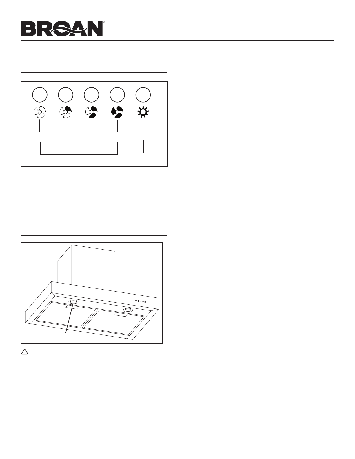
OPERATION
OFF
The hood is operated using the push buttons on the front panel.
Push the light button to turn the lights on and off.
Push the fan controls to select low, medium, or high blower
speed.
Push the OFF button to turn the blower off.
LOW
FAN CONTROLS
MED.
HIGH
LIGHT
ON/OFF
LIGHT BULBS
CLEANING AND MAINTENANCE
Proper maintenance of the Range Hood will assure proper
performance of the unit.
MOTOR
The motor is permanently lubricated and never needs oiling. If
the motor bearings make excessive or unusual noise, replace
the motor with the exact service motor. The impeller should also
be replaced.
GREASE FILTER
The grease filter should be cleaned frequently. Use a warm
detergent solution. Grease filter is dishwasher safe.
Clean all-metal filters in the dishwasher using a non-phosphate
detergent. Discoloration of the filter may occur if using phosphate
detergents, or as a result of local water conditions - but this will
not affect filter performance. This discoloration is not covered
by the warranty.
Remove grease filter by pushing back on the metal latch tab. This
will disengage the filter from the hood. Tilt the filter downward
and remove.
NON-DUCTED RECIRCULATION FILTERS
The non-ducted recirculation filters should be changed every
3-6 months. Replace more often if your cooking style generates
extra grease, such as frying and wok cooking.
Rotate the filters to remove them from the blower and replace.
LIGHT BULB COVER
WARNING
Bulbs may be hot. Always allow bulbs to cool down before
removing them.
This range hood requires two halogen bulbs (Type JC, 12V, 20W
Max, G-4 Base - included).
To change bulbs:
1. Remove light bulb cover by gently pushing it upward and
turning it counterclockwise.
2. Replace bulb.
3. Re-install light bulb cover by gently pushing it upward and
turning it clockwise.
STAINLESS STEEL CLEANING
DO:
• Regularly wash with clean cloth or rag soaked with warm
water and mild soap or liquid dish detergent.
• Alwayscleaninthedirectionoforiginalpolishlines.
• Alwaysrinsewellwithclearwater(2or3times)afterclean-
ing. Wipe dry completely.
• You may also use a specializedhousehold stainless steel
cleaner.
DON’T:
• Useanysteelorstainlesssteelwooloranyotherscrapersto
remove stubborn dirt.
• Useanyharshorabrasivecleansers.
• Allowdirttoaccumulate.
• Letplasterdustoranyotherconstructionresiduesreachthe
hood. During construction/renovation, cover the range hood
to make sure no dust sticks to the stainless steel surface.
Avoid: When choosing a detergent
• Anycleanersthatcontainbleachwillattackstainlesssteel
• Any productscontaining: chloride, fluoride,iodide, bromide
will deteriorate surfaces rapidly.
• Anycombustibleproductsusedforcleaningsuchasacetone,
alcohol, ether, benzol, etc., are highly explosive and should
never be used close to a range.
Page 3
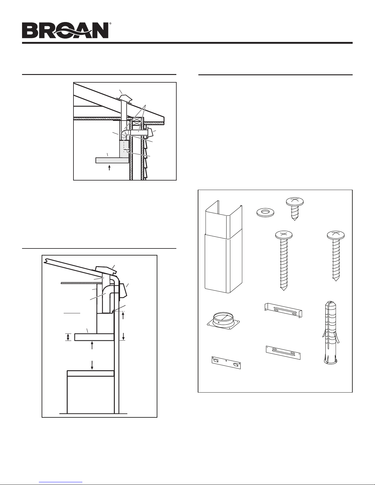
INSTALL THE DUCTWORK
MODELS B5330SS • B5336SS
Page 3
(Ducted Hoods Only)
1. Decide where
the ductwork
will run
between the
hood and the
outside.
2. A straight, short
duct run will
allow the hood
to perform most
efficiently.
3. Long duct
runs, elbows
and transitions
will reduce the
30" TO 36"
ABOVE COOKING SURFACE
performance of
the hood. Use as few of them as possible. Larger ducting
may be required for best performance with longer duct runs.
4. Install wall cap or roof cap. Connect round metal ductwork
to cap and work back towards the hood location. Use duct
tape to seal the joints between ductwork sections.
ROOF CAP
DECORATIVE
FLUE
HOOD
6"
ROUND DUCT
ROUND
ELBOW
3¼” FROM
WALL TO
DUCT
CENTERLINE
WALL CAP
MEASURE THE INSTALLATION
ROOF CAP
6” ROUND DUCT
DECORATIVE FLUE
ROUND ELBOW
HOOD
3-5/32”
WALL CAP
HOOD
MOUNTING
BRACKET
13-9/16”
TO CENTER OF
BRACKET HOLES
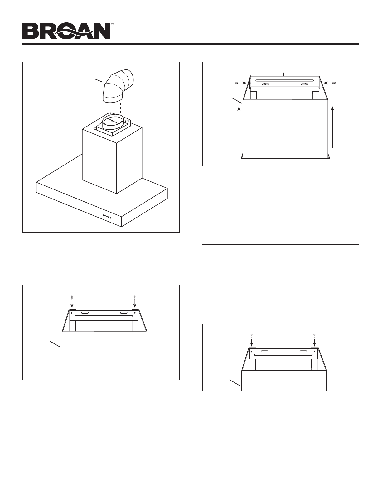
PREPARE THE HOOD
Unpack hood and check contents. You should receive:
1 - Hood
1 - Decorative Flue Assembly
1 - Damper / Duct Connector
1 - Lower Flue Mounting Bracket
1 - Upper Flue Mounting Bracket
1 - Hood Mounting Bracket
2 - Aluminum Grease Filters (installed in hood)
1 - Parts Bag containing:
8 - Mounting Screws (#8 x 3/8” Pan Head)
5 - Mounting Screws (#8 x 1-1/2” Flat Head)
2 - Mounting Screws (#8 x 1-3/16” Pan Head)
5 - Drywall Anchors
2 - Washers
1 - Installation Manual
8 MOUNTING
SCREWS (#8 x
3/8” Pan Head)
2 WASHERS
DECORATIVE FLUE
DAMPER / DUCT
CONNECTOR
5 MOUNTING
SCREWS
(#8 X 1-1/2”
Flat Head)
UPPER
FLUE MOUNTING
BRACKET
2 MOUNTING
SCREWS
(#8 X 1-3/16”
Pan Head)
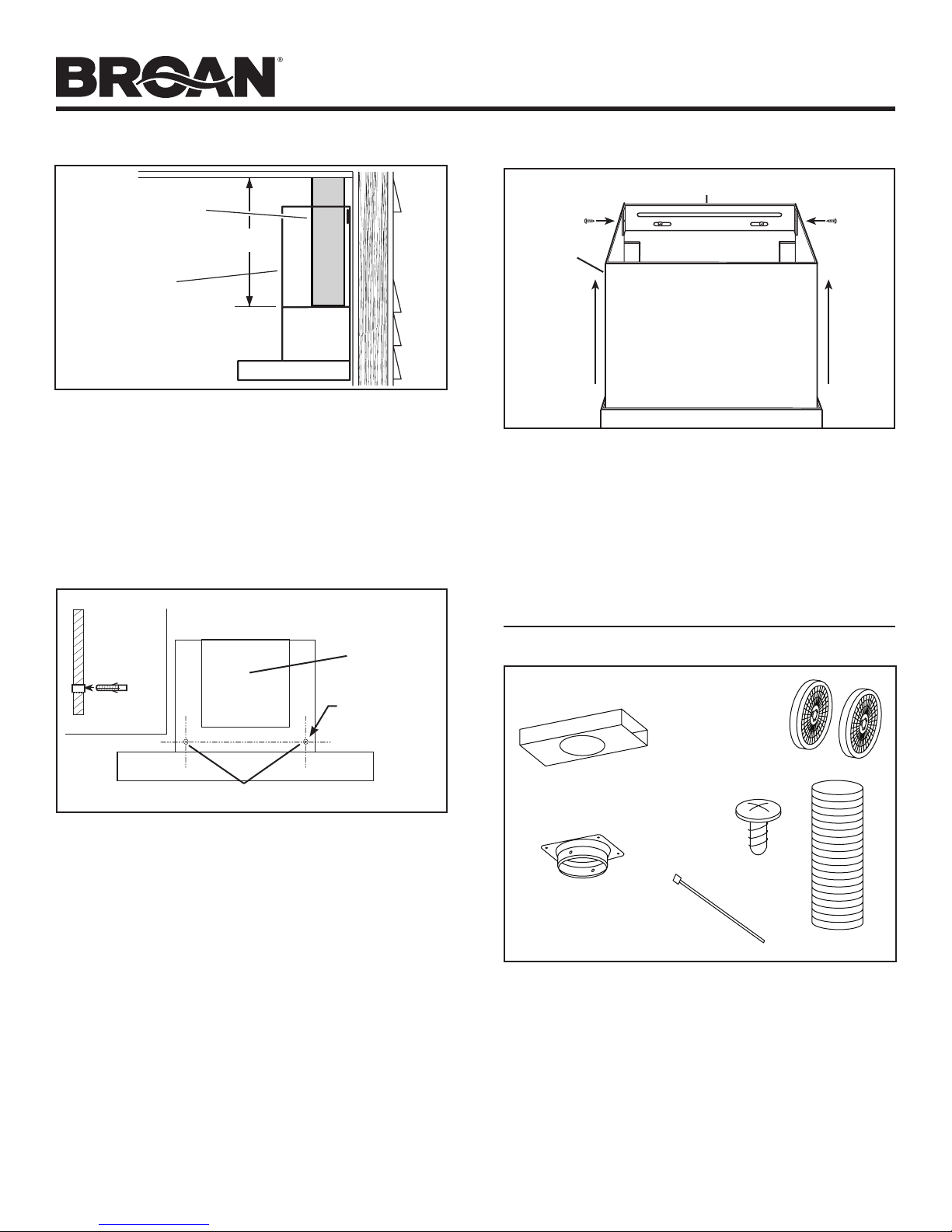
30” TO 36” ABOVE
COOKING SURFACE
A maximum of 36” above cooktop is recommended for best
capture of cooking impurities. The bottom of the hood MUST
NOT BE LESS than 30” above the cooktop.
Distances over 36” are at the installer and users discretion;
providing that the ceiling height permits.
HOOD MOUNTING
BRACKET
LOWER
FLUE MOUNTING
BRACKET
5 DRYWALL
ANCHORS
Page 4
MODELS B5330SS • B5336SS
”
Desired Hood Distance Above 36" High Cooktop (see note 1)
Notes:
1
bottom of the hood MUST NOT BE LESS than 30” above the cooktop. Distances over 36” above the cooktop
2
Page 4
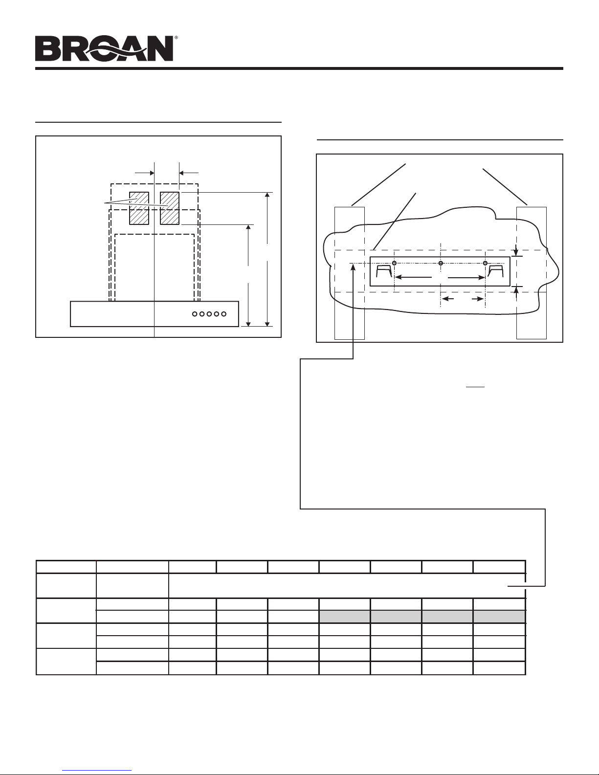
INSTALL THE WIRING
CENTER
LINE
LOCATE
ELECTRICAL
OUTLET
WITHIN THESE
AREAS.
(Verify location
will not interfere
with duct,
mounting
brackets
and flue.)
1. GROUNDING INSTRUCTIONS
This appliance must be grounded. In the event of an electrical short circuit, grounding reduces the risk of electric shock
by providing an escape wire for the electric current. This
appliance is equipped with a cord having a grounding wire
with a grounding plug. The plug must be plugged into an
outlet that is properly installed and grounded.
NOTE:
A recessed “clock” outlet is recommended.
2. Position the electrical outlet within the space covered by the
decorative flue and where it will not interfere with the round
duct. Make sure the outlet is no further than 14” from where
the cord exits from the hood and that the outlet does not
interfere with a mounting bracket fastening area or where the
decorative flue touches the wall.
5¼”
22
16”
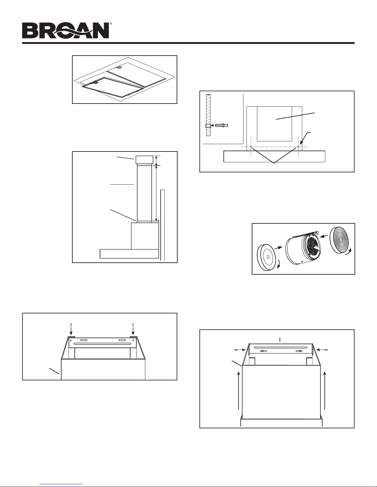
INSTALL THE HOOD MOUNTING
BRACKET
WALL STUDS
FRAMING BEHIND
DRYWALL
C
L
9”
4½”
43-9⁄16” = bottom of hood 30” above cooktop
49-9⁄16” = bottom of hood 36” above cooktop
1. Construct wood wall framing that is flush with interior surface
of wall studs.
Make sure:
a) the framing is centered over installation location.
b) the height of the framing will allow the mounting bracket
to be secured to the framing within the dimensions
shown.
2. After wall surface is finished, carefully center and level the
hood mounting bracket and secure it to wall framing with (3)
#8 x 1-1/2” mounting screws. Tighten the screws completely.
19⁄16”
30" 31" 32" 33" 34" 35" 36"
Ceiling
Height
8 Feet
9 Feet
10 Feet
(see note 2)
Duct
Method
Ducted
Non-Ducted
Ducted
Non-Ducted
Ducted
Non-Ducted
Mounting Bracket Mounting Holes Location Above 36" High Cooktop
43-9/16" 44-9/16" 45-9/16" 46-9/16" 47-9/16" 48-9/16" 49-9/16"
43-9/16" 44-9/16" 45-9/16"
43-9/16" 44-9/16" 45-9/16" 46-9/16" 47-9/16" 48-9/16" 49-9/16"
43-9/16" 44-9/16" 45-9/16" 46-9/16" 47-9/16" 48-9/16" 49-9/16"
43-9/16" 44-9/16" 45-9/16" 46-9/16" 47-9/16" 48-9/16" 49-9/16"
43-9/16" 44-9/16" 45-9/16" 46-9/16" 47-9/16" 48-9/16" 49-9/16"
A maximum height of 36” above the cooktop is recommended for best capture of cooking impurities. The
are at the installer’s and user’s discretion - providing that the ceiling height and flue length permit.
Requires 10-ft. flue extension accessory - Model Number FXN53SS.
Page 5
MODELS B5330SS • B5336SS
Page 5
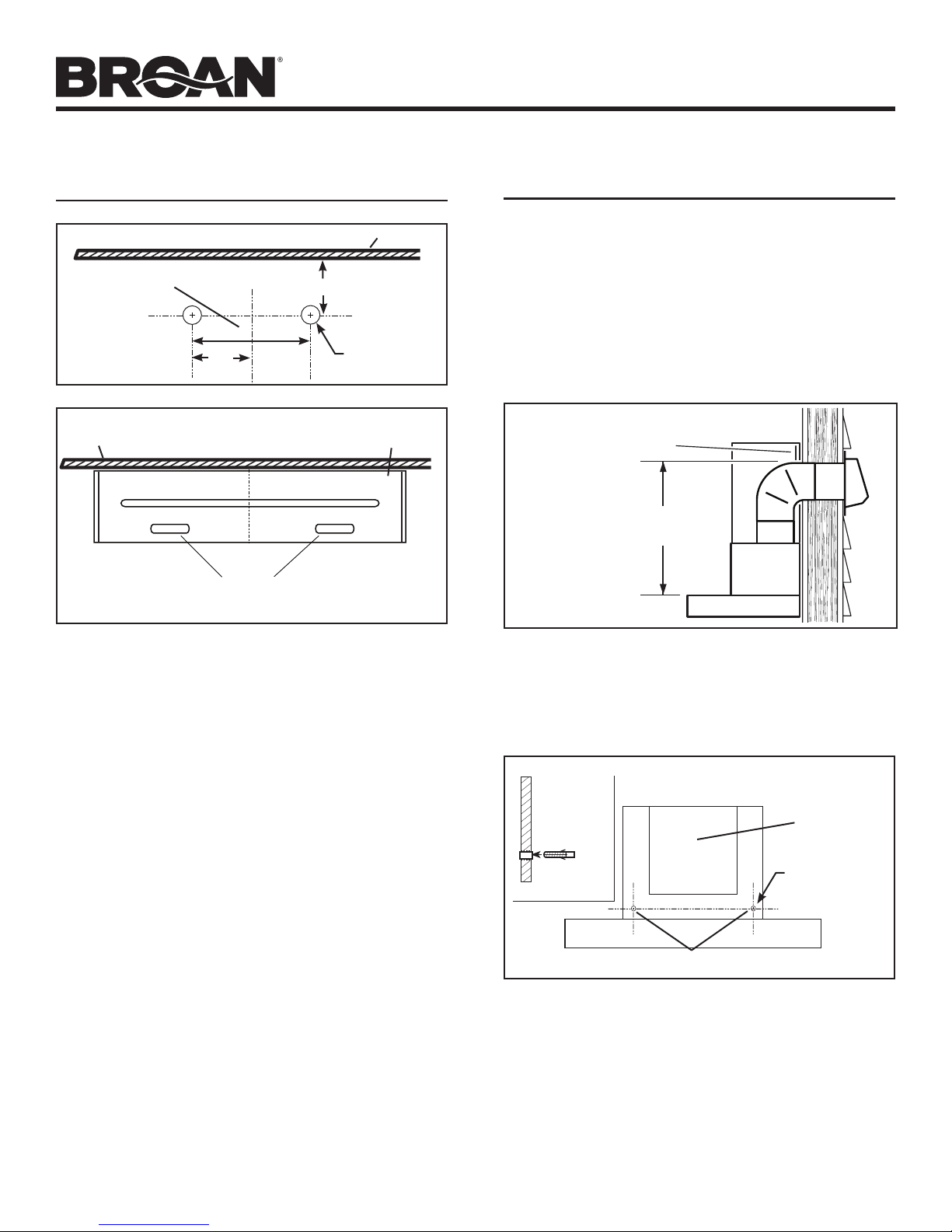
INSTALL UPPER FLUE MOUNTING
BRACKET
Ceiling
11⁄16”
Ø 5/16” TYP.
Flush with
the ceiling
Recommended
distance between
screw holes
Ceiling
Center of installation
C
L
7 1⁄4”
3¾”
Center of
installation
C
L
Upper flue mounting
bracket slots
INSTALL THE HOOD
(Horizontally Ducted Hoods Only)
1. DO NOT REMOVE the protective plastic film covering the
decorative flue and the hood at this time.
2. Lay the back side of the hood flat on a table. Use a piece of
cardboard to avoid damaging the table or the hood.
3. Attach damper / duct connector to top of hood using (4) #8
x 3/8” Pan Head mounting screws.
4. Remove the grease filters by pushing back the metal latch
tab and tilting filters downward to remove.
5. Carefully rotate hood upright.
LOWER FLUE
MOUNTING BRACKET
19”
MAX.
1. Drill two 5⁄16” diameter holes where shown. Insert drywall
anchors into the holes.
2. Center the bracket over the hood location and flush with the
ceiling. Make sure that the slots of the upper flue bracket are
at the bottom. Secure the upper flue bracket to the wall using
(2) #8 x 1½” mounting screws.
3. Tighten the screws completely. Make sure that the bracket
is tight against the wall.
6. To make sure there will be adequate clearance between top
of hood and lower flue mounting bracket for ductwork: Elbow
must be located below lower flue mounting bracket.
7. Align the hood and center it above the hood mounting
bracket. Gently lower the hood until it securely engages the
bracket.
INSIDE BACK OF HOOD
MOTOR/
BLOWER
ASSEMBLY
Ø 5/16” TYP.
SIDE VIEW
HOLE LOCATIONS
8. With the hood hanging in place, drill through both holes
located in the inside lower back of hood using a 5⁄16” drill bit.
Insert the included drywall anchors into the drilled holes (one
for each hole). Install (2) washers and (2) #8 x 1-3/16” pan
head mounting screws through the hood back and into the
drywall anchors. Verify that the hood is centered and leveled.
Tighten all screws completely.
9. Reinstall grease filters by aligning rear filter tabs with slots
in the hood. Push back the metal latch tab, push filter into
position and release. Make sure filters are securely engaged
after installation.
Page 6
MODELS B5330SS • B5336SS
Page 6
6” ROUND
DUCT ELBOW
10. Measure and install 6” round steel ductwork to roof cap or
wall cap and 90o elbow over duct collar on hood. Use duct
tape to make all joints secure and air tight.
11. Plug hood power cord into the outlet.
LOWER FLUE MOUNTING BRACKET
UPPER FLUE MOUNTING BRACKET
UPPER
FLUE
14. Slide the upper flue upward until it is aligned with its upper
mounting bracket. The bracket should be inside the flue.
Secure the upper flue to the upper flue mounting bracket
using (2) #8 x 3/8” mounting screws.
15. Remove any protective plastic remaining on hood.
INSTALL THE HOOD
(Vertically Ducted Hoods Only)
1. DO NOT REMOVE the protective plastic film covering the
decorative flue and the hood at this time.
2. Lay the back side of the hood flat on a table. Use a piece of
cardboard to avoid damaging the table or the hood.
3. Attach damper / duct connector to top of hood using (4) #8
x 3/8” Pan Head mounting screws.
4. Remove the grease filters by pushing back the metal latch
tab and tilting filters downward to remove.
5. Carefully rotate hood upright.
LOWER
FLUE
NOTE: 10-ft. ceilings require 10-ft. Flue Extension Model
FXN53SS (purchase separately). Discard the upper flue
supplied with your hood and replace it with the Model
FXN53SS flue extension.
12. Remove the upper flue from inside the lower flue. Install the
lower flue bracket to the lower flue using (2) flue bracket
screws #8 x 3/8”, make sure that the slots are at the top.
Remove protective plastic film covering the lower flue only.
Carefully replace the upper flue inside the lower flue.
13. Carefully place both flues into the recessed area of hood
top. Make sure tabs on the lower flue are pointing down and
engage with the slots on the top of the hood.
LOWER FLUE MOUNTING BRACKET
LOWER
FLUE
NOTE: 10-ft. ceilings require 10-ft. Flue Extension Model
FXN53SS (purchase separately). Discard the upper flue
supplied with your hood and replace it with the Model
FXN53SS flue extension.
6. Remove the upper flue from inside the lower flue. Install the
lower flue bracket to the lower flue using (2) flue bracket
screws #8 x 3/8”, make sure that the slots are at the top.
Remove protective plastic film covering both flues. Carefully
replace the upper flue inside the lower flue.
7. Carefully place both flues into the recessed area of hood
top. Make sure tabs on the lower flue are pointing down and
engage with the slots on the top of the hood.
Page 7
MODELS B5330SS • B5336SS
Page 7
6” ROUND
STEEL DUCT
DUCT LENGTH
DECORATIVE
FLUE
8. Measure and install steel ductwork to hood duct connector.
Use duct tape to make all joints secure and air tight.
9. Hold hood up close to wall mounting location and plug
power cord into wall outlet.
10. Align the hood and center it above the hood mounting
bracket. Make sure ductwork on hood lines up and attaches
to ductwork in ceiling. Gently lower the hood until it securely
engages the bracket.
11. Use duct tape to make all joints secure and air tight.
INSIDE BACK OF HOOD
UPPER FLUE MOUNTING BRACKET
UPPER
FLUE
14. Slide the upper flue upward until it is aligned with its mounting
bracket. The bracket should be inside the flue. Secure the
upper flue to the upper flue mounting bracket using (2) #8 x
3/8” mounting screws.
15. Remove any protective plastic remaining on hood.
INSTALL THE HOOD
(Non-Ducted Hoods Only)
MOTOR/
BLOWER
ASSEMBLY
Ø 5/16” TYP.
SIDE VIEW
HOLE LOCATIONS
12. With the hood hanging in place, drill through both holes
located in the inside lower back of hood using a 5⁄16” drill bit.
Insert the included drywall anchors into the drilled holes (one
for each hole). Install (2) washers and (2) #8 x 1-3/16” pan
head mounting screws through the hood back and into the
drywall anchors. Verify that the hood is centered and leveled.
Tighten all screws completely.
13. Reinstall grease filters by aligning rear filter tabs with slots
in the hood. Push back the metal latch tab, push filter into
position and release. Make sure filters are securely engaged
after installation.
NON-DUCT KIT MODEL RK56 CONTENTS
NON-DUCTED
RECIRCULATION
FILTERS
NON-DUCT
PLENUM
NON-DUCT PLENUM
COLLAR
NOTE: Non-ducted installations require Non-Duct Kit,
Model RK56 (purchase separately).
1. CAUTION: Do not use plastic or rigid metal duct.
2. Do not remove the protective plastic film covering the
decorative flue and the hood at this time.
3. Lay the back side of the hood flat on a table. Use a piece of
cardboard to avoid damaging the table or the hood.
4. Attach damper / duct connector to top of hood using (4) #8
x 3/8” Pan Head mounting screws.
5. Remove damper flaps from damper / duct connector and
discard flaps.
8 MOUNTING
SCREWS
(ST4 x 8
Round Head)
2 TIE
WRAPS
FLEXIBLE DUCT
Page 8
6. Remove the
grease filters
by pushing
back the
metal latch
tab and
tilting filters
downward to
remove.
7. Attach non-duct collar to non-duct plenum using (4) ST4 x
8 round head screws.
8. Measure distance “A”. This will be the length of the
extended flex duct.
MODELS B5330SS • B5336SS
Page 8
14. Hold hood up close to wall mounting location and plug
power cord into wall outlet.
15. Align the hood and center it above the hood mounting bracket.
Gently lower the hood until it securely engages the bracket.
INSIDE BACK OF HOOD
MOTOR/
BLOWER
ASSEMBLY
Ø 5/16” TYP.
SIDE VIEW
9. Attach
aluminum
NON-DUCT PLENUM
3-5/8”
flexible
duct to the
damper / duct
connector
6” ALUMINUM
FLEX DUCT
A
with a tie
wrap.
10. Attach flexible
DAMPER / DUCT
CONNECTOR
duct to nonduct plenum
collar and
secure with
tie wrap. Tape
all joints with
duct tape.
NOTE: 10-ft. ceilings require 10-ft. Flue Extension Model
FXN53SS (purchase separately). Discard the upper flue
supplied with your hood and replace it with the Model
FXN53SS flue extension.
LOWER FLUE MOUNTING BRACKET
HOLE LOCATIONS
16. With the hood hanging in place, drill through both holes
located in the inside lower back of hood using a 5⁄16” drill
bit. Insert the included drywall anchors into the drilled
holes (one for each hole). Install (2) washers and (2) #8 x
1-3/6” pan head mounting screws through the back of the
hood and into the drywall anchors. Verify that the hood is
centered and leveled. Tighten all screws completely.
17. Attach (2)
two non-duct
recirculation
filters to sides
of blower by
aligning key lock
slot and rotating
until filters lock
into place.
For replacement
non-duct recirculation filters - purchase S97018030 or
ROUNDFILTER.
18. Reinstall grease filters by aligning rear filter tabs with slots
in the hood. Push back the metal latch tab, push filter
into position and release. Make sure filters are securely
engaged after installation.
LOWER
FLUE
11. Remove the upper flue from inside the lower flue. Install the
lower flue bracket to the lower flue using (2) flue bracket
screws #8 x 3/8”, make sure that the slots are at the top.
Remove protective plastic film covering both flues. Carefully
replace the upper flue inside the lower flue.
12. Carefully place both flues into the recessed area of hood
top. Make sure tabs on the lower flue are pointing down and
engage with the slots on the top of the hood.
13. Attach non-duct plenum with collar to upper flue using (4)
ST4 x 8 round head screws.
UPPER FLUE MOUNTING BRACKET
UPPER
FLUE
19. Slide the upper flue upward until it is aligned with its mounting
bracket. The bracket should be inside the flue. Secure the
upper flue to the upper flue mounting bracket using (2) #8 x
3/8” mounting screws.
20.
Remove any protective plastic remaining on hood.
Page 9
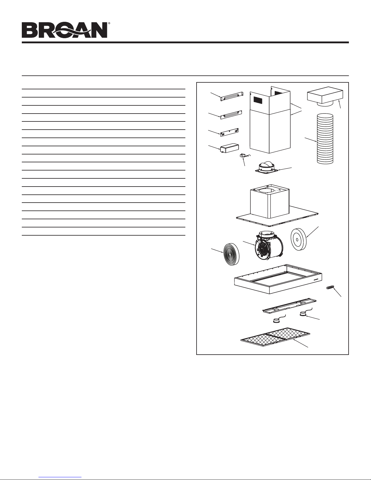
SERVICE PARTS
MODELS B5330SS • B5336SS
Page 9
KEY PART NO. DESCRIPTION QTY.
1 S99528454 Decorative Upper and Lower Flues 1
2 S99526974 Motor / Blower Assembly 1
3 S99526975 Light Socket Assembly 2
4 S99527010 Light Trim Ring / Lens Assembly 2
5 S99526976 Push Button Assembly 1
6 S97018027 Aluminum Grease Filters (2 per hood) B5330SS 1
S97018028 Aluminum Grease Filters (3 per hood) B5336SS 1
7 S97018030 Non-Duct Recirculation Filters (pair) 1
8 S99526983 Damper / Duct Connector 1
9 S99526984 6” Dia. Expandable Flexible Aluminum Duct 1
10 S99526985 Non-Duct Plenum Assembly 1
11 S99526987 Hood Mounting Bracket 1
12 S99526989 Lower Flue Mounting Bracket 1
13 S99526991 Upper Flue Mounting Bracket 1
14 S99527012 Capacitor 1
15 S99527013 Plastic Cover 1
S99527011 Transformer (not shown) 1
S99528455 Parts Bag (not shown) 1
Order service parts by Part No. - not by Key No.
12
11
15
13
1
10
9
14
8
7
2
7
5
3, 4
6
Replacement parts can be ordered on our website:
www.broan.com
Page 10

MODÈLES B5330SS • B5336SS
!
!
!
!
Pour enregistrer ce produit,
HOTTE DE
visitez : www.broan.com
CUISINE À CHEMINÉE
LIRE CES DIRECTIVES ET LES CONSERVER
Pour usage domestIque seulement.
Page 10
AVERTISSEMENT
AFIN DE RÉDUIRE LES RISQUES D’INCENDIE, DE CHOC
ÉLECTRIQUE OU DE BLESSURES CORPORELLES,
VEUILLEZ OBSERVEZ LES DIRECTIVES SUIVANTES :
1. N’utilisez cet appareil que de la manière prévue par le fabricant.
Si vous avez des questions, communiquez avec le fabricant à
l’adresse ou au numéro de téléphone indiqués dans la garantie.
2. Avant de procéder à l’entretien ou au nettoyage de l’appareil, coupez
l’alimentation du panneau électrique et verrouillez l’interrupteur
principal afin d’empêcher que le courant ne soit accidentellement
rétabli. S’il est impossible de verrouiller l’interrupteur principal,
fixez solidement un message d’avertissement, par exemple une
étiquette, sur le panneau électrique.
3. L’installation et les branchements électriques doivent être effectués
par un personnel compétent, conformément aux normes et aux
codes en vigueur, y compris les normes et les codes du bâtiment
relatifs à la résistance au feu.
4. Pour éviter les refoulements, l’apport d’air doit être suffisant pour
brûler les gaz produits par les appareils à combustion et les
évacuer dans le conduit de fumée (cheminée). Respectez les
directives du fabricant de l’appareil de chauffage et les normes de
sécurité, notamment celles publiées par la National Fire Protection
Association (NFPA), l’American Society for Heating, Refrigeration
and Air Conditioning Engineers (ASHRAE) et les codes des
autorités locales.
5. Ce produit peut comporter des arêtes tranchantes. Prenez garde
aux coupures et aux éraflures lors de l’installation et du nettoyage.
6. Veillez à ne pas endommager le câblage électrique ou d’autres
équipements non apparents lors de la découpe ou du perçage du
mur ou du plafond.
7. Les ventilateurs canalisés doivent toujours rejeter l’air à l’extérieur.
8. N’utilisez pas de commande de régime à semi-conducteurs
avec cet appareil.
9. Pour réduire les risques d’incendie, utilisez seulement des conduits
en acier.
10. Cet appareil doit être relié à une mise à la terre.
POUR RÉDUIRE LES RISQUES D’INCENDIE CAUSÉS PAR
DE LA GRAISSE SUR LE PLAN DE CUISSON :
a) Ne laissez jamais les éléments de surface allumés à haute
température. Les débordements peuvent causer de la fumée et
occasionner des écoulements de graisse inflammables. L’huile doit
être chauffée graduellement à basse ou à moyenne température.
b) Mettez toujours la hotte en MARCHE lors de la cuisson à feu vif
ou lors de la cuisson d’aliments à flamber (par ex., crêpes Suzette,
cerises jubilé, bœuf au poivre flambé).
c) Nettoyez souvent la hotte. Ne laissez pas la graisse s’accumuler sur
le ventilateur ou les filtres.
d) Utilisez des casseroles de dimension appropriée. Utilisez
toujours une batterie de cuisine adaptée à la dimension de la
surface chauffante.
AVERTISSEMENT
OBSERVEZ LES CONSIGNES SUIVANTES AFIN DE
RÉDUIRE LES RISQUES DE BLESSURES CORPORELLES
EN CAS D’INCENDIE CAUSÉ PAR DE LA GRAISSE SUR LE
PLAN DE CUISSON* :
1. ÉTOUFFEZ LES FLAMMES à l’aide d’un couvercle étanche,
d’une tôle à biscuits ou d’un plateau en métal puis éteignez le
brûleur. FAITES ATTENTION DE NE PAS VOUS BRÛLER. SI LES
FLAMMES NE S’ÉTEIGNENT PAS IMMÉDIATEMENT, QUITTEZ
LES LIEUX ET APPELEZ LE SERVICE DES INCENDIES.
2. NE SOULEVEZ JAMAIS UNE CASSEROLE EN FLAMMES – vous
pourriez vous brûler.
3. N’UTILISEZ PAS D’EAU, ni de linges ou de serviettes mouillés –
une violente explosion de vapeur pourrait survenir.
4. Utilisez un extincteur SEULEMENT si :
A. Vous savez qu’il est de classe ABC et vous connaissez déjà son
mode de fonctionnement.
B. L’incendie n’est pas très important et ne se propage pas.
C. Vous avez déjà téléphoné au service des incendies.
D. Vous pouvez combattre l’incendie en faisant dos à une sortie.
* Conseils tirés de la publication de la NFPA « Kitchen Fire Safety Tips ».
ATTENTION
1. Pour une utilisation en intérieur seulement.
2. Cet appareil ne doit servir qu’à la ventilation générale. Ne pas
l’utiliser pour l’évacuation de matières ou de vapeurs dangereuses
ou explosives.
3. Pour ne pas endommager les roulements du moteur, déséquilibrer
les pales ou les rendre bruyantes, protégez l’appareil de la
poussière de plâtre, de construction, etc.
4. Ne pas utiliser cette hotte au-dessus d’un appareil de cuisson
dépassant 60 000 BTU/heure car le moteur du ventilateur s’arrêtera
par intermittence.
5. Le moteur de la hotte est muni d’un dispositif de protection de
surcharge électrique qui coupe automatiquement le moteur en
cas de surchauffe. Il se remet en marche lorsqu’il a refroidi.
Faites réparer la hotte si le moteur continue à fonctionner
par intermittence.
6. Une hauteur maximale de 91,4 cm (36 po) au-dessus de la table de
cuisson est recommandé pour une meilleure évacuation des odeurs
de cuisson. Le fond de la hotte DOIT ÊTRE AU MINIMUM à 76 cm
(30 po)au-dessus de la table de cuisson.
7. Il est recommandé que les installateurs soient deux, compte tenu
de la taille de cette hotte.
8. Pour réduire les risques d’incendie et évacuer l’air correctement,
assurez-vous qu’il est canalisé à l’extérieur. Ne pas évacuer l’air
dans des espaces enfermés par des murs ou un plafond ou dans
un grenier, un vide sanitaire ou un garage.
9. Prenez garde en installant la cheminée décorative et la hotte, car
elles peuvent comporter des bords tranchants.
10. Veuillez lire l’étiquette de spécifications du produit pour obtenir plus
de renseignements, notamment sur les exigences.
INSTALLATEUR : VEUILLEZ REMETTRE CE GUIDE AU PROPRIÉTAIRE.
PROPRIÉTAIRE : DIRECTIVES DE NETTOYAGE, D’ENTRETIEN ET D’UTILISATION À LA PAGE 11.
Page 11

MODÈLES B5330SS • B5336SS
!
!
!
Page 11
FONCTIONNEMENT
ARRÊT
La hotte fonctionne à l’aide de quatre (4) boutons-poussoirs
situés sur la face avant.
Allumez et éteignez la lumière à l’aide du bouton d’éclairage.
Actionnez le ventilateur à l’aide des boutons de régime lent,
moyen ou élevé.
Appuyez sur le bouton OFF pour arrêter le ventilateur.
RÉGIME
LENT
COMMANDES DU VENTILATEUR
RÉGIME
MOYEN
RÉGIME
ÉLEVÉ
MARCHE/ARRÊT
LUMIÈRE
AMPOULES
NETTOYAGE ET ENTRETIEN
Un entretien adéquat de la hotte assurera son bon
fonctionnement.
MOTEUR
Le moteur est lubrifié en permanence et n’a pas besoin d’être
huilé. Si les roulements du moteur sont anormalement bruyants,
remplacez le moteur exactement par le même modèle. La roue à
ailettes doit aussi être remplacée.
FILTRE À GRAISSES
Le filtre à graisses doit être nettoyé fréquemment. Utilisez une
solution tiède de détergent. Le filtre à graisses est lavable au
lave-vaisselle.
Nettoyez les filtres entièrement métalliques au lave-vaisselle avec
un détergent sans phosphate. Une décoloration du filtre peut se
produire si des détergents phosphatés sont utilisés et selon les
conditions locales de l’eau, sans toutefois affecter le rendement
du filtre. Cette décoloration n’est pas couverte par la garantie.
Enlevez le filtre à graisse en repoussant la languette métallique
de retenue. Le filtre se dégagera de la hotte. Inclinez le filtre vers
le bas et enlevez-le.
FILTRES DE RECIRCULATION POUR INSTALLATION SANS
CONDUIT
Dans une installation sans conduit, les filtres de recirculation
doit être remplacé tous les trois à six mois. Remplacez-les plus
souvent si le type de cuisine produit plus de graisses, telle que
la friture et la cuisson au wok.
Tournez les filtres pour les dégager du ventilateur et les remplacer.
COUVERCLE DES AMPOULES
AVERTISSEMENT
Les ampoules peuvent être très chaudes. Laissez toujours
les ampoules refroidir avant de les enlever.
Cette hotte requiert deux ampoules halogènes (type JC, 12 volts,
20 watts max., base G4 - inclus).
Pour remplacer les ampoules :
1. Enlevez le couvercle des ampoules en le poussant
délicatement vers le haut et en le tournant dans le sens
antihoraire.
2. Remplacez la ou les ampoules.
3. Replacez le couvercle en le poussant délicatement vers le
haut et en le tournant dans le sens horaire.
NETTOYAGE DE L’ACIER INOXYDABLE
À FAIRE :
• Régulièrement, nettoyez toutes les surfaces avec un chiffon
propre imbibé d’eau tiède et de savon doux ou de liquide à
vaisselle.
• Nettoyeztoujoursdanslesensdeslignesdupolioriginal.
• Rincez toujoursàl’eaupropre(2ou3fois) aprèslenettoyage.
Séchez complètement en essuyant.
• Vous pouvezégalementutiliser unnettoyantspécial pouracier
inoxydable.
À NE PAS FAIRE :
• N’utilisez pas de laine d’acier ordinaire ni de laine d’acier
inoxydable ou tout genre de grattoir pour déloger la saleté.
• N’utilisezaucunnettoyantpuissantouabrasif.
• Nelaissezpaslasaletés’accumuler.
• Protégez la hotte de la poussière de plâtre ou de tout autre
résidu de construction. Pendant des travaux de construction ou
de rénovation, couvrez la hotte pour empêcher la poussière de
toucher aux surfaces d’acier inoxydable.
À éviter : Lors du choix d’un détergent
• Tout nettoyant contenant de l’eau de javel attaquera l’acier
inoxydable.
• Toutproduitcontenant:duchlore,dufluor,del’iodeoudubrome
détériorera rapidement les surfaces.
• Toutproduitcombustibleutilisépourlenettoyagecommel’acétone,
l’alcool, l’éther, le benzol, etc., est hautement explosif et ne doit
jamais être utilisé à proximité d’une hotte.
Page 12

INSTALLATION DES CONDUITS
MODÈLES B5330SS • B5336SS
Page 12
(hottes avec conduits seulement)
1. Planifiez
la pose du
conduit en
déterminant
son tracé entre
la hotte et
l’extérieur de la
maison.
2. Un tracé droit
et court permet
à la hotte d’être
plus efficace.
3. Des conduits
longs, des
coudes et des
transitions
réduisent
l’efficacité de la hotte. N’en utilisez que le moins possible.
Pour plus d’efficacité, des conduits plus gros peuvent être
nécessaires si le parcours est trop long.
4. Installez le capuchon mural ou de toit. Connectez un
conduit rond en métal au chapeau en progressant vers
la hotte. Scellez les joints avec du ruban à conduit à
chaque section.
CAPUCHON DE TOIT
CONDUIT
DÉCORATIF
HOTTE
30 PO À 36 PO AU-DESSUS
DU PLAN DE CUISSON
CONDUIT ROND
DE 15,2 CM (6 PO)
CAPUCHON
MURAL
COUDE
ROND
3¼ PO DE
MUR À LA
LIGNE DE
CENTRE DE
CONDUITE
MESURES DE L’INSTALLATION
CAPUCHON DE TOIT
CONDUIT ROND
15,2 CM (6 PO)
CONDUIT DÉCORATIF
COUDE ROND
8,02 CM
(3-5/32 PO)
30 PO À 36 PO AU-DESSUS
DU PLAN DE CUISSON
HOTTE
CAPUCHON
MURAL
SUPPORT DE
MONTAGE DE
LA HOTTE
13-9/16 PO (34,4 CM)
AU CENTRE
DES TROUS
DU SUPPORT
PRÉPARATION DE LA HOTTE
Déballez la hotte et vérifiez le contenu de la boîte. Celle-ci doit
contenir les éléments suivants :
1 - Hotte
1 - Conduit décoratif de cheminée
1 - Clapet / raccord de conduit
1 - Bride de montage de conduit décoratif inférieur
1 - Bride de montage de conduit décoratif supérieur
1 - Support de hotte
2 - Filtres à graisse en aluminium (installés dans la hotte)
1 - Sac de pièces contenant :
8 - Vis de montage (n° 8 x 3/8 po à tête cylindrique)
5 - Vis de montage (n° 8 x 1-1/2 po à tête plate)
2 - Vis de montage (n° 8 x 1-3/16 po à tête cylindrique)
5 - Chevilles d’ancrage pour cloisons sèches
2 - Rondelles
1 - Manuel d’installation
8 - VIS DE
MONTAGE
(n° 8 x 3/8 po
à tête cylindrique)
2 - VIS DE
MONTAGE
(n° 8 x 1-3/16 po
à tête
cylindrique)
5 CHEVILLES
D'ANCRAGE
(n° 8 x 1-1/2 po
CONDUIT DÉCORATIF
DE CONDUIT DÉCORATIF
CLAPET / RACCORD
DE CONDUIT
BRIDE
DE MONTAGE
DE HOTTE
2 RONDELLES
5 - VIS DE
MONTAGE
à tête plate)
BRIDE DE MONTAGE
SUPÉRIEUR
BRIDE DE MONTAGE
DE CONDUIT
DÉCORATIF INFÉRIEUR
Un maximum de 91,4 cm (36 po) est également recommandé
pour mieux capter les vapeurs de cuisson. La distance minimale
de la hotte au-dessus de la surface de cuisson NE DOIT PAS
ÊTRE INFÉRIEURE à 76 cm (30 po).
Une distance de plus de 91,4 cm (36 po) est laissée à la
discrétion de l’installateur et des utilisateurs si la hauteur du
plafond le permet.
Page 13

MODÈLES B5330SS • B5336SS
Distance voulue de la hotte au-dessus d’une surface de cuisson à 91,4 cm (36 po) (voir remarque 1)
Remarques
1.
Les distances de plus de 91,4 cm (36 po) sont laissées à la discrétion de l'installateur et de l'utilisateur si la hauteur
2.
Page 13
INSTALLATION DU CÂBLAGE INSTALLATION DE LA BRIDE DE
MONTAGE DE LA HOTTE
LIGNE DE
PLACER LA
PRISE DE
COURANT
DANS CES
ZONES.
(Vérifier qu’elle
de nuit pas au
conduit, aux
brides de
montage
et au conduit
décoratif.)
CENTRE
13,3 cm
(5¼ po)
55,9 cm
(22 po)
40,6 cm
(16 po)
POTEAUX MURAUX
CHARPENTE DERRIÈRE
LA CLOISON SÈCHE
C
L
22,9 cm (9 po)
11,4 cm
(4½ po)
4 cm (1 9⁄16 po)
1. INSTRUCTIONS DE MISE À LA TERRE
Cet appareil doit être correctement mis à la terre. Dans
l’éventualité d’un court-circuit, la mise à la terre réduit les
risques de choc électrique en permettant au courant de
s’échapper dans un fil. Cette appareil comporte un cordon
électrique muni d’un fil et d’une fiche de mise à la terre.
Cette fiche doit être branchée dans une prise de courant
correctement installée et mise à la terre.
REMARQUE :
Une prise encastrée pour « horloge » est recommandée.
2. Placez la prise de courant dans l’espace recouvert par le
conduit décoratif de cheminée et à un endroit où elle ne nuira
pas au passage du conduit rond. Elle ne doit pas être à plus
de 35,6 cm (14 po) du point où le cordon sort de la hotte et ne
pas empiéter sur la zone de fixation d’un support de montage
et de l’endroit où le conduit décoratif touche au mur.
76,2 cm (30 po) 78,7 cm (31 po) 81,3 cm (32 po) 83,8 cm (33 po) 86,4 cm (34 po) 88,9 cm (35 po) 91,4 cm (36 po)
Hauteur
du plafond
244 cm (8 pi)
274 cm (9 pi)
305 cm (10 pi)
(voir remarque 2)
Méthode de
canalisation
Avec conduits
Sans conduits
Avec conduits
Sans conduits
Avec conduits
Sans conduits
Emplacement des trous de la bride de montage au-dessus d’une
surface de cuisson à 91,4 cm (36 po)
110,6 cm (43-9/16 po)113,2 cm (44-9/16 po)115,7 cm (45-9/16 po)118,3 cm (46-9/16 po)120,8 cm (47-9/16 po)123,3 cm (48-9/16 po)
110,6 cm (43-9/16 po)113,2 cm (44-9/16 po)115,7 cm (45-9/16 po)
110,6 cm (43-9/16 po)113,2 cm (44-9/16 po)115,7 cm (45-9/16 po)118,3 cm (46-9/16 po)120,8 cm (47-9/16 po)123,3 cm (48-9/16 po)125,9 cm (49-9/16 po)
110,6 cm (43-9/16 po)113,2 cm (44-9/16 po)115,7 cm (45-9/16 po)118,3 cm (46-9/16 po)120,8 cm (47-9/16 po)123,3 cm (48-9/16 po)125,9 cm (49-9/16 po)
110,6 cm (43-9/16 po)113,2 cm (44-9/16 po)115,7 cm (45-9/16 po)118,3 cm (46-9/16 po)120,8 cm (47-9/16 po)123,3 cm (48-9/16 po)125,9 cm (49-9/16 po)
110,6 cm (43-9/16 po)113,2 cm (44-9/16 po)115,7 cm (45-9/16 po)118,3 cm (46-9/16 po)120,8 cm (47-9/16 po)123,3 cm (48-9/16 po)125,9 cm (49-9/16 po)
1. Construisez une charpente de bois qui affleure la surface
intérieure des montants du mur.
Prenez soin :
a) de centrer cette charpente avec l’emplacement
b) de donner une hauteur suffisante à la charpente afin de
2. Une fois la surface du mur finie, centrez la bride de montage
bien de niveau et fixez-la à la charpente à l’aide de trois (3)
vis n° 8 x 1 ½ po. Serrez complètement les vis.
110,6 cm (43-9⁄16 po) = bas de la hotte à 76 cm (30
po) au-dessus de la surface de cuisson
125,9 cm (49-9⁄16 po) = bas de la hotte à 91,4 cm (36
po) au-dessus de la surface de cuisson
d’installation.
pouvoir y fixer solidement la bride de montage selon les
mesures indiquées.
125,9 cm (49-9/16 po)
:
La distance minimale de la hotte au-dessus de la surface de cuisson ne doit pas être inférieure à 76.2 cm (30 po).
Un maximum de 91,4 cm (36 po) est également fortement recommandé pour mieux capter les vapeurs de cuisson.
du plafond et la longueur du conduit décoratif le permettent.
Exige la rallonge de conduit décoratif de 305 cm (10 pi) - numéro de modèle FXN53SS.
Page 14

INSTALLATION DE LA BRIDE DE MONTAGE
DE CONDUIT DÉCORATIF SUPÉRIEUR
MODÈLES B5330SS • B5336SS
Page 14
INSTALLATION DE LA HOTTE
(hotte à conduits horizontaux seulement)
Plafond
Ø 7,9 mm
(5/16 po) TYP.
Au ras
du plafond
Distance
recommandée
entre les vis
Plafond
Centre de l’installation
C
2,7 cm (1-1⁄16 po)
L
18,4 cm (7¼ po)
9,5 cm
(3¾ po)
Centre de
l’installation
C
L
Fentes de la bride de montage
de conduit décoratif supérieur
1. Percez deux trous de 7,9 mm (5/16 po) de diamètre aux endroits
illustrés. Insérez les chevilles d’ancrage dans les trous.
2. Centrez la bride à l’emplacement de la hotte au ras avec le plafond.
Assurez-vous que les fentes de la bride supérieure sont en bas.
Fixez la bride supérieure au mur avec deux (2) vis de n° 8 x 1 ½ po.
3. Serrez complètement les vis. Assurez-vous que la bride est
fermement appuyée contre le mur.
1. N’ENLEVEZ PAS À CETTE ÉTAPE la pellicule protectrice en plastique
recouvrant la hotte et le conduit décoratif de cheminée.
2. Placez la hotte sur une table, sur le dos. Utilisez un carton pour éviter
d’endommager la table ou la hotte.
3. Fixez le clapet / raccord de conduit au sommet du boîtier de la hotte à
l’aide de (4) vis n° 8 x 3/8 po à tête cylindrique.
4. Enlevez les filtres à graisse en repoussant la languette métallique et en
basculant les filtres vers le bas.
5. Avec précaution, tournez la hotte à la verticale.
BRIDE DE MONTAGE
DE CONDUIT
DÉCORATIF
INFÉRIEUR
MAX. 48,3 CM
(19 PO)
6. Assurez-vous qu’il y a suffisamment d’espace entre le haut de hotte
et la bride de montage inférieure pour laisser passer le conduit. Le
coude doit être situé en dessous de la bride de montage inférieure.
7. Alignez la hotte et centrez-la au-dessus de sa bride de montage.
Abaissez doucement la hotte jusqu’à ce qu’elle s’engage solidement
dans la bride.
INTÉRIEUR DE L’ARRIÈRE DE LA HOTTE
ENSEMBLE
MOTEUR /
VENTILATEUR
Ø 7,9 MM
VUE LATÉRALE
POSITION DES TROUS
8. La hotte étant suspendue en place, percez à travers les deux trous
situés à l’intérieur de l’arrière du boîtier de la hotte à l’aide d’une
mèche de 7,9 mm (5/16 po). Insérez les chevilles d’ancrage dans
les trous percés (une dans chaque trou). Installez (2) rondelles et
(2) vis de montage n° 8 x 1-3/16 po à tête cylindrique à travers
l’arrière de la hotte et dans les chevilles d’ancrage. Vérifiez que la
hotte est centrée et de niveau. Serrez complètement les vis.
9. Pour remettre les filtres à graisse, alignez les ergots arrière
des filtres dans les fentes de la hotte. Repoussez la languette
métallique, poussez les filtres en place et relâchez. Vérifiez si les
filtres sont bien fixés une fois replacés.
(5/16 PO) TYP.
Page 15

MODÈLES B5330SS • B5336SS
Page 15
CONDUIT ROND
ET COUDE DE
15,2 CM (6 PO)
10. Mesurez et installez un conduit rond de 15,2 cm (6 po) jusqu’au
capuchon de toit ou capuchon mural et un coude de 90° sur le
raccord de conduit de la hotte. Utilisez du ruban pour conduit afin
de fixer solidement tous les joints et les étancher.
11. Branchez le cordon électrique de la hotte dans la prise.
BRIDE DE MONTAGE DE CONDUIT DÉCORATIF INFÉRIEUR
BRIDE DE MONTAGE DU CONDUIT DÉCORATIF SUPÉRIEUR
CONDUIT
DÉCORATIF
SUPÉRIEUR
14. Glissez le conduit décoratif supérieur vers le haut jusqu’à ce qu’il
soit aligné avec sa bride de montage supérieure. La bride doit être à
l’intérieur du conduit décoratif. Fixez le conduit supérieur à la bride
supérieure avec deux (2) vis de n° 8 x 3/8 po.
15. Enlevez le reste de pellicule protectrice en plastique de la hotte.
INSTALLATION DE LA HOTTE
(hotte à conduits verticaux seulement)
1. N’ENLEVEZ PAS À CETTE ÉTAPE la pellicule protectrice en plastique
recouvrant la hotte et le conduit décoratif de cheminée.
2. Placez la hotte sur une table, sur le dos. Utilisez un carton pour éviter
d’endommager la table ou la hotte.
3. Fixez le clapet / raccord de conduit au sommet du boîtier de la hotte à
l’aide de (4) vis n° 8 x 3/8 po à tête cylindrique.
4. Enlevez les filtres à graisse en repoussant la languette métallique et en
basculant les filtres vers le bas.
5. Avec précaution, tournez la hotte à la verticale.
CONDUIT
DÉCORATIF
INFÉRIEUR
REMARQUE : Les plafonds de 3 m (10 pi) exigent la
Rallonge de conduit décoratif pour plafonds de 3 m (10
pi), modèle FXN53SS, pour les installations avec ou sans
conduits (vendue séparément). Jetez le conduit décoratif
supérieur fourni avec votre hotte et remplacez-le par la
rallonge de conduit décoratif, modèle FXN53SS.
12. Enlevez la section supérieure de conduit décoratif qui se trouve à
l’intérieur du conduit inférieur. Fixez la bride sur le conduit décoratif
inférieur à l’aide de (2) vis n° 8 x 3/8 po. Assurez-vous que les fentes
sont en haut. Replacez soigneusement le conduit décoratif supérieur
à l’intérieur des deux conduits. Glissez soigneusement le conduit
décoratif supérieur à l’intérieur du conduit décoratif inférieur.
13. Placez soigneusement les conduits décoratifs dans l’espace
au-dessus de la hotte. Assurez-vous que les onglets du conduit
décoratif inférieur pointent vers le bas et s’engagent dans les fentes
du dessus de la hotte.
BRIDE DE MONTAGE DE CONDUIT DÉCORATIF INFÉRIEUR
CONDUIT
DÉCORATIF
INFÉRIEUR
REMARQUE : Les plafonds de 3 m (10 pi) exigent la Rallonge de
conduit décoratif pour plafonds de 3 m (10 pi), modèle FXN53SS
(vendue séparément). Jetez le conduit décoratif supérieur fourni
avec votre hotte et remplacez-le par la rallonge de conduit
décoratif, modèle FXN53SS.
6. Enlevez la section supérieure de conduit décoratif qui se trouve à
l’intérieur du conduit inférieur. Fixez la bride sur le conduit décoratif
inférieur à l’aide de (2) vis n° 8 x 3/8 po en vous assurant que les
fentes sont en haut. Enlevez la pellicule protectrice en plastique
recouvrant les deux conduits décoratifs. Glissez soigneusement le
conduit décoratif supérieur à l’intérieur du conduit décoratif inférieur.
7. Placez soigneusement les conduits décoratifs dans l’espace
au-dessus de la hotte. Assurez-vous que les onglets du conduit
décoratif inférieur pointent vers le bas et s’engagent dans les fentes
du dessus de la hotte.
Page 16

MODÈLES B5330SS • B5336SS
Page 16
CONDUIT ROND
DE 15,2 CM (6 PO)
LONGUEUR DU CONDUIT
CONDUIT
DÉCORATIF
8. Mesurez et fixez le conduit en acier sur le raccord de la hotte.
Utilisez du ruban pour conduit afin de fixer solidement tous les joints
et les étancher.
9. Soulevez la hotte, maintenez-la près de son emplacement et
branchez son cordon électrique dans la prise.
10. Alignez la hotte et centrez-la au-dessus de sa bride de montage.
Assurez-vous qu’elle est alignée avec le conduit du plafond et fixez
celui-ci. Abaissez doucement la hotte jusqu’à ce qu’elle s’engage
solidement dans la bride.
11. Utilisez du ruban pour conduit afin de fixer solidement tous les joints
et les étancher.
INTÉRIEUR DE L’ARRIÈRE DE LA HOTTE
ENSEMBLE
MOTEUR /
VENTILATEUR
Ø 7,9 MM
VUE LATÉRALE
(5/16 PO) TYP.
BRIDE DE MONTAGE DE CONDUIT DÉCORATIF SUPÉRIEUR
CONDUIT
DÉCORATIF
SUPÉRIEUR
14. Glissez le conduit décoratif supérieur vers le haut jusqu’à ce qu’il
soit aligné avec sa bride de montage. La bride doit être à l’intérieur
du conduit décoratif. Fixez le conduit supérieur à la bride supérieure
avec deux (2) vis de n° 8 x 3/8 po.
15. Enlevez le reste de pellicule protectrice en plastique de la hotte.
INSTALLATION DE LA HOTTE
(hotte sans conduits seulement)
CONTENU DE L’ENSEMBLE MODÈLE RK56
POUR HOTTE SANS CONDUITS
FILTRES DE
RECIRCULATION
POUR INSTALLATION
SANS CONDUITS
POSITION DES TROUS
12. La hotte étant suspendue en place, percez à travers les deux trous
situés à l’intérieur de l’arrière du boîtier de la hotte à l’aide d’une
mèche de 7,9 mm (5/16 po). Insérez les chevilles d’ancrage dans
les trous percés (une dans chaque trou). Installez (2) rondelles et
(2) vis de montage n° 8 x 1-3/16 po à tête cylindrique à travers
l’arrière de la hotte et dans les chevilles d’ancrage. Vérifiez que la
hotte est centrée et de niveau. Serrez complètement les vis.
13. Pour remettre les filtres à graisse, alignez les ergots arrière
des filtres dans les fentes de la hotte. Repoussez la languette
métallique, poussez les filtres en place et relâchez. Vérifiez si les
filtres sont bien fixés une fois replacés.
CAISSON
NON CANALISÉ
COLLIER DE CAISSON
NON CANALISÉ
REMARQUE : Les installations sans conduits nécessitent l’ensemble
sans conduits, modèle RK56 (vendu séparément).
1. ATTENTION : N’utilisez pas de conduit en métal rigide ou
en plastique.
2. N’enlevez pas à cette étape la pellicule protectrice en plastique
recouvrant la hotte et le conduit décoratif de cheminée.
3. Placez la hotte sur une table, sur le dos. Utilisez un carton pour
éviter d’endommager la table ou la hotte.
4. Fixez le clapet / raccord de conduit au sommet du boîtier de la hotte
à l’aide de (4) vis n° 8 x 3/8 po à tête cylindrique.
5. Enlevez les clapets de l’ensemble clapet / raccord de conduit
et jetez-les.
8 VIS DE
MONTAGE
(ST4 x 8 à
tête ronde)
2 ATTACHES
AUTOBLOCANTES
CONDUIT FLEXIBLE
Page 17

MODÈLES B5330SS • B5336SS
6. Enlevez les
filtres à graisse
en repoussant
la languette
métallique et en
basculant les
filtres vers le
bas.
7. Fixez le collier
d’installation
sans conduits au caisson non canalisé à l’aide de (4) vis ST4 x 8
à tête ronde.
8. Mesurez la distance « A ». Elle correspondra à la longueur du
conduit flexible allongé.
9. Fixez le conduit
flexible en
aluminium au
clapet / raccord
de conduit
avec l’attache
autoblocante.
CAISSON NON CANALISÉ
CONDUIT FLEXIBLE EN
ALUMINIUM
DE 15,2 CM (6 PO)
9,2 CM
(3 5/8 PO)
A
10. Fixez le
conduit flexible
au collier
CLAPET / RACCORD
DE CONDUIT
du caisson
avec l’attache
autoblocante.
Scellez tous les
joints avec du
ruban à conduit.
REMARQUE : Les
plafonds de 3 m
(10 pi) exigent la
Rallonge de conduit décoratif pour plafonds de 3 m (10 pi), modèle
FXN53SS, pour les installations avec ou sans conduits (vendue
séparément). Jetez le conduit décoratif supérieur fourni avec
votre hotte et remplacez-le par la rallonge de conduit décoratif,
modèle FXN53SS.
BRIDE DE MONTAGE DE CONDUIT DÉCORATIF INFÉRIEUR
Page 17
14. Soulevez la hotte, maintenez-la près de son emplacement et
branchez son cordon électrique dans la prise.
15. Alignez la hotte et centrez-la au-dessus de sa bride de montage.
Abaissez doucement la hotte jusqu’à ce qu’elle s’engage solidement
dans la bride.
INTÉRIEUR DE L’ARRIÈRE DE LA HOTTE
ENSEMBLE
MOTEUR /
VENTILATEUR
Ø 7,9 MM
VUE LATÉRALE
POSITION DES TROUS
16. La hotte étant suspendue en place, percez à travers les deux trous
situés à l’intérieur de l’arrière du boîtier de la hotte à l’aide d’une
mèche de 7,9 mm (5/16 po). Insérez les chevilles d’ancrage dans
les trous percés (une dans chaque trou). Installez (2) rondelles et
(2) vis de montage n° 8 x 1-3/16 po à tête cylindrique à travers
l’arrière de la hotte et dans les chevilles d’ancrage. Vérifiez que la
hotte est centrée et de niveau. Serrez complètement les vis.
17. Fixez deux
(2) filtres de
recirculation
aux côtés du
ventilateur en
alignant le cran
de retenue sur
la fente et en
tournant les filtres
en place.
Pour remplacer les filtres de recirculation - veuillez acheter les
filtres S97018030 ou FILTRES RONDS.
18. Pour remettre les filtres à graisse, alignez les ergots arrière
des filtres dans les fentes de la hotte. Repoussez la languette
métallique, poussez les filtres en place et relâchez. Vérifiez si les
filtres sont bien fixés une fois replacés.
(5/16 PO) TYP.
CONDUIT
DÉCORATIF
INFÉRIEUR
11. Enlevez la section supérieure de conduit décoratif qui se trouve à
l’intérieur du conduit inférieur. Fixez la bride sur le conduit décoratif
inférieur à l’aide de (2) vis n° 8 x 3/8 po en vous assurant que les
fentes sont en haut. Enlevez la pellicule protectrice en plastique
recouvrant les deux conduits décoratifs. Glissez soigneusement le
conduit décoratif supérieur à l’intérieur du conduit décoratif inférieur.
12. Placez soigneusement les conduits décoratifs dans l’espace
au-dessus de la hotte. Assurez-vous que les onglets du conduit
décoratif inférieur pointent vers le bas et s’engagent dans les fentes
du dessus de la hotte.
13. Fixez le caisson non canalisé et son collier au conduit décoratif
supérieur à l’aide de (4) vis ST4 x 8 à tête ronde.
BRIDE DE MONTAGE DU CONDUIT DÉCORATIF SUPÉRIEUR
CONDUIT
DÉCORATIF
SUPÉRIEUR
19. Glissez le conduit décoratif supérieur vers le haut jusqu’à ce qu’il
soit aligné avec sa bride de montage. La bride doit être à l’intérieur
du conduit décoratif. Fixez le conduit supérieur à la bride supérieure
avec deux (2) vis de n° 8 x 3/8 po.
20. Enlevez le reste de pellicule protectrice en plastique de la hotte.
Page 18

PIÈCES DE RECHANGE
N° DE N° DE
REPÈRE PIÈCE DESCRIPTION QTÉ
1 S99528454 Conduits décoratifs supérieur et inférieur 1
2 S99526974 Ensemble moteur / ventilateur 1
3 S99526975 Ensemble de douille d’ampoule 2
4 S99527010 Ensemble d’anneau de finition / lentille d’éclairage 2
5 S99526976 Ensemble de boutons-poussoirs 1
6 S97018027 Filtres à graisses en aluminium (2 par hotte) B5330SS 1
S97018028 Filtres à graisses en aluminium (3 par hotte) B5336SS 1
7 S97018030 Filtres de recirculation pour installation sans conduits (paire) 1
8 S99526983 Clapet / raccord de conduit 1
9 S99526984 Conduit d’aluminium flexible de 15,2 cm (6 po) extensible 1
10 S99526985 Ensemble de caisson non canalisé 1
11 S99526987 Bride de montage de hotte 1
12 S99526988 Bride de montage de conduit décoratif inférieur 1
13 S99526990 Bride de montage de conduit décoratif supérieur 1
14 S99527012 Condensateur 1
15 S99527013 Couvercle en plastique 1
S99527011 Transformateur (non illustré) 1
S99528455 Sachet de pièces (non illustré) 1
Veuillez commander les pièces par n° de pièce et non par n° de repère.
12
11
15
13
MODÈLES B5330SS • B5336SS
Page 18
14
1
9
8
10
7
2
7
3, 4
6
Les pièces de rechange peuvent être commandées sur
notre site : www.broan.com.
5
Page 19

MODELOS B5330SS• B5336SS
!
!
!
!
Para registrar este producto
CAMPANA DE
visite: www.broan.com
ESTUFA DE CHIMENEA
LEA Y CONSERVE ESTAS INSTRUCCIONES
IndIcada solamente Para cocInar en casa.
Página 19
ADVERTENCIA
PARA REDUCIR EL RIESGO DE INCENDIOS, DESCARGAS
ELÉCTRICAS O LESIONES PERSONALES OBSERVE LAS
SIGUIENTES PRECAUCIONES:
1. Use la unidad sólo de la manera indicada por el fabricante.
Si tiene preguntas, comuníquese con el fabricante a la dirección o
al número telefónico que se incluye en la garantía.
2. Antes de dar servicio o limpiar la unidad, interrumpa el suministro
eléctrico en el panel de servicio y bloquee los medios de
desconexión del servicio para evitar que la electricidad sea
reanudada accidentalmente. Cuando no sea posible bloquear los
medios de desconexión del servicio, fije firmemente una señal
de advertencia (como una etiqueta) en un lugar visible del panel
de servicio.
3. Sólo personal calificado debe realizar el trabajo de instalación y
el cableado eléctrico, de acuerdo con todos los códigos y normas
correspondientes, incluidos los códigos y normas de construcción
específicos sobre protección contra incendios.
4. Se necesita suficiente aire para que se lleve a cabo una combustión
adecuada y la extracción de los gases a través del tubo de humos
(chimenea) del equipo quemador de combustible, con el fin de evitar
las contracorrientes. Siga las directrices y las normas de seguridad
del fabricante del equipo de calefacción, como las publicadas por
la Asociación Nacional de Protección contra Incendios (National
Fire Protection Association, NFPA), la Sociedad Americana de
Ingenieros en Calefacción, Refrigeración y Aire Acondicionado
(American Society for Heating, Refrigeration and Air Conditioning
Engineers, ASHRAE) y las autoridades de los códigos locales.
5. Este producto puede tener bordes afilados. Tenga cuidado para
evitar cortes y abrasiones durante la instalación o la limpieza.
6. Al cortar o perforar a través de la pared o del techo, tenga cuidado
de no dañar el cableado eléctrico ni otros servicios ocultos.
7. Los ventiladores en conductos siempre deben ventearse hacia
el exterior.
8. No use esta unidad junto con ningún dispositivo de control de
velocidad de estado sólido.
9. Para reducir el riesgo de incendio, use solamente conductos
de acero.
10. Esta unidad debe conectarse a tierra.
PARA REDUCIR EL RIESGO DE INCENDIO PROVOCADO
POR GRASA PRESENTE EN LA ESTUFA:
a) Nunca deje desatendidas las unidades de la superficie cuando
estén en ajustes altos de calor. Los alimentos en ebullición
provocan derrames grasosos y con humo que se pueden incendiar.
Caliente el aceite lentamente en ajustes de calor bajo o medio.
b) Siempre ENCIENDA la campana cuando esté cocinando a altas
temperaturas o flameando alimentos (por ejemplo, crepas Suzette,
cerezas Jubilee, bistec con pimienta flameado).
c) Limpie frecuentemente los ventiladores. No permita la acumulación
de grasa en el ventilador ni en el filtro.
d) Use una cacerola del tamaño adecuado. Siempre use utensilios
de cocina que sean apropiados para el tamaño del elemento de
la superficie.
ADVERTENCIA
PARA REDUCIR EL RIESGO DE LESIONES PERSONALES
EN EL CASO DE QUE LA GRASA DE LA ESTUFA SE
INCENDIE, OBSERVE LAS SIGUIENTES PRECAUCIONES*:
1. APAGUE LAS LLAMAS con una tapa de ajuste exacto, una charola
para galletas o una bandeja de metal, y después apague el quemador.
PROCEDA CON CUIDADO PARA EVITAR QUEMADURAS.
SI LAS LLAMAS NO SE APAGAN INMEDIATAMENTE, EVACÚE
EL ÁREA Y LLAME AL DEPARTAMENTO DE BOMBEROS.
2. NUNCA LEVANTE UNA CACEROLA INCENDIADA, se puede
quemar.
3. NO USE AGUA ni toallas húmedas, ya que provocará una violenta
explosión de vapor.
4. Use un extintor SÓLO si:
A. El extintor es clase ABC y usted sabe cómo usarlo.
B. El incendio es pequeño y está confinado al área en la que
se inició.
C. Se ha llamado al departamento de bomberos.
D. Puede combatir el incendio teniendo la espalda orientada hacia
una salida.
*Basado en “Kitchen Fire Safety Tips” (Sugerencias para la seguridad
contra incendios en la cocina) publicado por NFPA.
PRECAUCIÓN
1. Para uso en interiores solamente.
2. Sólo para usarse como medio de ventilación general. No debe
usarse para la extracción de materiales ni vapores peligrosos
o explosivos.
3. Para evitar daños a los cojinetes del motor y rotores ruidosos o
desbalanceados, mantenga la unidad de potencia protegida contra
rociados de yeso, polvos de construcción, etc.
4. No use equipo para cocinar mayor de 60,000 BTU/hr, pues el motor
ventilador se apagará de manera intermitente.
5. Este motor de campana tiene una protección contra sobrecargas
térmicas que automáticamente apagará el motor en caso de
sobrecalentamiento. El motor reanudará su funcionamiento cuando
se enfríe. Si el motor continúa apagándose y encendiéndose,
solicite servicio para la campana.
6. Se recomienda una altura máxima de 36 pulg. (91.4 cm) por encima
de la estufa para mejor las impurezas al cocinar. La parte inferior de
la campana NO DEBE ESTAR A MENOS de 30 pulg. (76 cm) por
encima de la estufa.
7. Se recomienda que dos personas hagan la instalación debido al
gran tamaño de esta campana.
8. Para reducir el riesgo de incendio y para descargar adecuadamente
el aire, asegúrese de dirigir el aire hacia el exterior. No descargue
el aire en espacios contenidos entre paredes o cielos rasos, ni en
áticos, sótanos bajos ni en la cochera.
9. Tenga cuidado al instalar el tubo de humos decorativo y la
campana; pueden tener bordes afilados.
10. Lea la etiqueta de especificaciones que tiene el producto para ver
información y requisitos adicionales.
INSTALADOR: DEJE ESTA GUÍA CON EL PROPIETARIO DE LA VIVIENDA.
PROPIETARIO DE LA VIVIENDA: EN LA PÁGINA 20 ENCONTRARÁ INFORMACIÓN DE OPERACIÓN Y MANTENIMIENTO.
Page 20

MODELOS B5330SS• B5336SS
!
!
Página 20
FUNCIONAMIENTO
APAGADO
La campana se hace funcionar con los botones en el panel
frontal.
Presione el botón de la luz para encender y apagar las luces.
Presione los controles del ventilador para seleccionar la
velocidad baja, media o alta del ventilador.
Presione el botón de APAGADO para apagar el ventilador.
BAJO
CONTROLES DEL VENTILADOR
MEDIO
ALTO
LUZ
ENCENDIDO/
APAGADO
BOMBILLAS
CUBIERTA DE LA BOMBILLA DE LUZ
ADVERTENCIA
Las bombillas podrían estar calientes. Siempre permita que
se enfríen las bombillas antes de cambiarlas.
Esta campana de estufa requiere dos bombillas de halógeno
(tipo JC, 12 V, 20 W máximo y base G-4 - incluye).
Para cambiar las bombillas:
1. Retire la cubierta de la bombilla de luz empujándola
suavemente hacia arriba y girándola en sentido contrahorario.
2. Reemplace la bombilla.
3. Reinstale la cubierta de la bombilla de luz empujándola
suavemente hacia arriba y girándola en sentido horario.
LIMPIEZA Y MANTENIMIENTO
El mantenimiento correcto de la campana de la estufa asegurará el funcionamiento adecuado de la unidad.
MOTOR
El motor está permanentemente lubricado y nunca necesitará
ponerle aceite. Si los cojinetes del motor están haciendo ruido
excesivo o inusual, reemplace el motor con el motor de servicio
exacto. También debe reemplazar el impulsor.
FILTRO DE GRASA
El filtro de grasa se debe limpiar con frecuencia, con una solución
tibia de detergente y agua. El filtro de grasa se puede lavar en
el lavaplatos.
Limpie los filtros completamente metálicos en el lavaplatos con un
detergente sin fosfatos. El filtro se puede decolorar si se utilizan
detergentes con fosfatos o como resultado de la condición del
agua local, pero esto no afectará el desempeño del filtro. Esta
decoloración no está cubierta por la garantía.
Retire el filtro de la grasa empujando hacia atrás la cejilla
metálica. Esto desacoplará al filtro de la campana. Incline el filtro
hacia abajo y retírelo.
FILTROS DE RECIRCULACIÓN PARA SISTEMAS SIN
CONDUCTOS
Los filtros de recirculación para sistemas sin conductos se debe
cambiar cada 3-6 meses. Cámbielo con más frecuencia si su
estilo de cocinar genera más grasa, como al freír y al cocinar en
una sartén china de cuenco redondo.
Gire los filtros para retirarlos del ventilador y reemplace.
LIMPIEZA DEL ACERO INOXIDABLE
COSAS QUE PUEDE HACER:
• Regularmente, lave con una tela o trapo limpioremojado con
agua tibia y jabón o detergente líquido para platos.
• Siemprelimpieenladireccióndelaslíneasoriginalesdepulido.
• Siempre enjuaguebienconagualimpia (2o3veces)después
de la limpieza. Séquelo por completo.
• También puede usar un limpiador casero especializado para
acero inoxidable.
COSAS QUE NO DEBE HACER:
• Usar lana de acero o acero inoxidable ni algún otro tipo de
raspador para quitar mugre difícil de sacar.
• Usarlimpiadoresfuertesniabrasivos.
• Dejarqueseacumulelamugre.
• Dejar que el polvo forme plastas ni que quede en la campana
algún otro residuo de la construcción. Durante la construcción
o la renovación, cubra la campana para estar seguro de que el
polvo no se pegue a la superficie de acero inoxidable.
Evite: Al elegir un detergente
• Todolimpiadorquecontengablanqueador, puesatacaráal acero
inoxidable.
• Todo producto que contenga: cloruro, fluoruro, yoduro, bromuro,
pues deteriorará las superficies rápidamente.
• Todo producto combustible utilizado para la limpieza, como
acetona, alcohol, éter, benzol, etc., pues son altamente explosivos
y nunca se deben usar cerca de una estufa.
Page 21

INSTALE LOS CONDUCTOS
MODELOS B5330SS• B5336SS
Página 21
(sólo en campanas con conductos)
1. Decida dónde
instalará el
conducto entre
la campana y el
exterior.
2. Un conducto
recto y corto
permitirá que
la campana
TUBO DE HUMOS
funcione más
eficientemente.
3. Los tramos
largos de
conductos,
codos y
transiciones
reducirán el
rendimiento de
DE 30 A 36 PULG. (76 A 91.4 CM)
POR ENCIMA DE LA
SUPERFICIE DE COCINADO
la campana.
Use tan pocos de ellos como sea posible. Es posible que se
requieran conductos más grandes para un mejor funcionamiento
con tramos más largos de conductos.
4. Instale la tapa para pared o techo. Conecte un conducto metálico
redondo en la tapa y trabaje hacia atrás, hacia la ubicación de la
campana. Use cinta para conductos para sellar las uniones entre
las secciones de conductos.
TAPÓN DE TECHO
DECORATIVO
CAMPANA
CONDUCTO REDONDO
DE 6 pulg. (15.2 cm)
TAPÓN DE
PARED
CODO
REDONDO
3¼ PULG.
(8.3 CM) DE
PARED A LA
LÍNEA
CENTRAL DEL
CONDUCTO
MIDA LA INSTALACIÓN
TAPA DE TECHO
CONDUCTO REDONDO
DE 6 PULG. (15.2 CM)
TUBO DE HUMOS
DECORATIVO
CODO REDONDO
CAMPANA
3-5/32 PULG.
(8.02 CM)
DE 30 A 36 PULG. (76 A 91.4 CM)
POR ENCIMA DE LA
SUPERFICIE DE COCINADO
TAPA DE PARED
SOPORTE
PARA MONTAR
LA CAMPANA
13-9/16 PULG. (34.4 CM)
AL CENTRO DE LOS
ORIFICIOS DEL SOPORTE
PREPARE LA CAMPANA
Desempaque la campana y revise el contenido del paquete. Debe
contener lo siguiente:
1 campana
1 conjunto del tubo de humos decorativo
1 conector del regulador de tiro/conducto
1 soporte de montaje del tubo de humos inferior
1 soporte de montaje del tubo de humos superior
1 soporte de montaje de la campana
2 filtros de aluminio para grasa (instalados en la campana)
1 bolsa de piezas con:
8 tornillos de montaje (8 x 3/8 pulg. de cabeza troncocónica)
5 tornillos de montaje (8 x 1-1/2 pulg. de cabeza plana)
2 tornillos de montaje (8 x 1-3/16 pulg. de cabeza troncocónica)
5 taquetes para placa de yeso
2 arandelas
1 manual de instalación
8 TORNILLOS
DE MONTAJE
(8 X 3/8 PULG.
2 ARANDELAS
5 TORNILLOS
DE MONTAJE
DE CABEZA
TUBO DE HUMOS
DECORATIVO
MONTAJE DEL TUBO
DE HUMOS SUPERIOR
CONECTOR DEL
REGULADOR DE
TIRO/CONDUCTO
SOPORTE DE MONTAJE
DE LA CAMPANA
(8 x 1-1/2
PULG.
PLANA)
SOPORTE DE
SOPORTE DE
MONTAJE DEL TUBO
DE HUMOS INFERIOR
DE CABEZA
TRONCOCÓNICA)
2 TORNILLOS
DE MONTAJE
(8 x 1-3/16 PULG.
DE CABEZA
TRONCO-
CÓNICA)
5 TAQUETES PARA
PLACA DE YESO
Se recomienda una distancia máxima de 36 pulg. (91.4 cm) sobre la
superficie de la estufa para la mejor captura de las impurezas resultantes del cocinado. La distancia mínima de la campana sobre la
superficie de la estufa NO DEBE SER MENOR de 30 pulg. (76 cm).
Utilizar distancias superiores a las 36 pulg. (91.4 cm) quedan a discreción del usuario y del instalador, siempre y cuando lo permita la altura
hasta el cielo raso.
Page 22

MODELOS B5330SS• B5336SS
Distancia deseada de la campana por encima de la estufa de 36 pulg. (91.4 cm) de alto (vea la nota 1)
Notas
1.
2.
INSTALE EL CABLEADO INSTALE EL SOPORTE DE
MONTAJE DE LA CAMPANA
LÍNEA
LOCALICE EL
TOMACORRIENTE
ELÉCTRICO
DENTRO DE
ESTAS ÁREAS.
(Verifique que la
ubicación no
interfiera con el
conducto, los
soportes de
montaje y el tubo
de humos.)
CENTRAL
5¼ pulg.
(13.3 cm)
22 pulg.
(55.9 cm)
16 pulg.
(40.6 cm)
MONTANTES DE PARED
MARCO DETRÁS DE LA
PLACA DE YESO
C
L
9 pulg. (22.9 cm)
4½ pulg.
(11.4 cm)
Página 22
1 9⁄16 pulg.
(4 cm)
1. INSTRUCCIONES PARA LA PUESTA A TIERRA
Este aparato debe estar conectado a tierra. En caso de un
corto circuito eléctrico, la puesta a tierra reduce el riesgo de
una descarga eléctrica al suministrar un cable de escape
para la corriente eléctrica. Este aparato está equipado
con un cordón que tiene un cable con una clavija a tierra.
La clavija debe conectarse a una toma eléctrica que esté
instalada y conectada a tierra adecuadamente.
NOTA:
Se recomienda un tomacorriente de “reloj” ahuecado.
2. Coloque el tomacorriente eléctrico dentro del espacio cubierto
por el tubo de humos decorativo y donde no interfiera con el
conducto redondo. Asegúrese de que el tomacorriente no esté
a más de 14 pulg (35,6 cm) de donde sale el cordón de la
campana y que el tomacorriente no interfiera con un área de
sujeción de soportes o donde el tubo de humos toque la pared.
Altura
del techo
8 pies (244 cm)
9 pies (274 cm)
10 pies (305 cm)
(vea la nota 2)
Método de
conductos
Con conductos
Sin conductos
Con conductos
Sin conductos
Con conductos
Sin conductos
30 pulg. (76.2 cm) 31 pulg. (78.7 cm) 32 pulg. (81.3 cm) 33 pulg. (83.8 cm) 34 pulg. (86.4 cm) 35 pulg. (88.9 cm) 36 pulg. (91.4 cm)
Ubicación de los orificios de montaje del soporte por encima
de la estufa de 36 pulg. (91.4 cm) de alto
43 9/16 pulg. (110.6 cm) 44 9/16 pulg. (113.2 cm) 45 9/16 pulg. (115.7 cm) 46 9/16 pulg. (118.3 cm) 47 9/16 pulg. (120.8 cm) 48 9/16 pulg. (123.3 cm)
43 9/16 pulg. (110.6 cm) 44 9/16 pulg. (113.2 cm) 45 9/16 pulg. (115.7 cm)
43 9/16 pulg. (110.6 cm) 44 9/16 pulg. (113.2 cm) 45 9/16 pulg. (115.7 cm) 46 9/16 pulg. (118.3 cm) 47 9/16 pulg. (120.8 cm) 48 9/16 pulg. (123.3 cm) 49 9/16 pulg. (125.9 cm)
43 9/16 pulg. (110.6 cm) 44 9/16 pulg. (113.2 cm) 45 9/16 pulg. (115.7 cm) 46 9/16 pulg. (118.3 cm) 47 9/16 pulg. (120.8 cm) 48 9/16 pulg. (123.3 cm) 49 9/16 pulg. (125.9 cm)
43 9/16 pulg. (110.6 cm) 44 9/16 pulg. (113.2 cm) 45 9/16 pulg. (115.7 cm) 46 9/16 pulg. (118.3 cm) 47 9/16 pulg. (120.8 cm) 48 9/16 pulg. (123.3 cm) 49 9/16 pulg. (125.9 cm)
43 9/16 pulg. (110.6 cm) 44 9/16 pulg. (113.2 cm) 45 9/16 pulg. (115.7 cm) 46 9/16 pulg. (118.3 cm) 47 9/16 pulg. (120.8 cm) 48 9/16 pulg. (123.3 cm) 49 9/16 pulg. (125.9 cm)
1. Construya un bastidor de madera en la pared que quede
al ras de la superficie interior de los montantes de la pared.
Asegúrese de que:
a) el bastidor esté centrado en el lugar de la instalación.
b) la altura del bastidor permita fijar el soporte de montaje
en el bastidor dentro de las dimensiones mostradas.
2. Después de terminar con la superficie de la pared, centre
con cuidado y nivele el soporte de montaje de la campana,
y asegúrelo al bastidor de la pared con tres (3) tornillos de
montaje de 8 x 1 1/2 pulg. Apriete totalmente los tornillos.
43-9⁄16 (110.6 cm) = parte interior de la campana,
30 pulg. (76 cm) arriba de la estufa
49-9⁄16 (125.9 cm) = parte interior de la campana,
36 pulg. (91.4 cm)
arriba de la estufa
:
La distancia mínima de la campana sobre la superficie de la estufa no debe ser menor de 30 pulg. (76.2 cm).
Se recomienda enfáticamente una distancia máxima de 36 pulg. (91.4 cm) sobre la superficie de la estufa para
capturar mejor las impurezas resultantes del cocinado. Las distancias mayores de 36 pulg. (91.4 cm) sobre la
superficie de la estufa se dejan a criterio de la persona que hace la instalación y del usuario, siempre y cuando la
altura del cielo raso y la longitud del tubo de humos lo permitan.
Requiere un accesorio de extensión de tubo de humos de 10 pies (305 cm) – Modelo número FXN53SS.
49 9/16 pulg. (125.9 cm)
Page 23

INSTALE EL SOPORTE DE MONTAJE DEL
TUBO DE HUMOS SUPERIOR
MODELOS B5330SS• B5336SS
Página 23
INSTALE LA CAMPANA (sólo para
campanas con conductos horizontales)
Centro de la instalación
Distancia
recomendada entre
los orificios de los
tornillos
Cielo raso
C
L
7¼ pulg. (18.4 cm)
3¾ pulg.
(9,5 cm)
Centro de la
instalación
C
L
1-1⁄16 pulg. (2.7 cm)
Cielo raso
Ø 5/16 pulg.
(7.9 mm) Típico
A nivel con
el cielo raso
Ranuras del soporte de montaje
del tubo de humos superior
1. Perfore dos orificios de 5/16 pulg. (7.9 mm) de diámetro donde se
muestra. Inserte los taquetes para placa de yeso en los orificios.
2. Centre el soporte sobre la ubicación de la campana y a nivel con
el cielo raso. Asegúrese de que las ranuras del soporte del tubo de
humos superior estén en la parte inferior. Fije el soporte del tubo de
humos superior a la pared utilizando dos (2) tornillos de montaje de
8 x 1 1/2 pulg.
3. Apriete totalmente los tornillos. Asegúrese de que el soporte esté
apretado contra la pared.
1. En este momento NO QUITE la película de plástico protector que cubre
el tubo de humos decorativo y la campana.
2. Deje la parte posterior de la campana plana sobre una mesa. Utilice un
pedazo de cartón para evitar dañar la mesa o la campana.
3. Fije el conector del regulador/conducto en la parte superior de la
campana utilizando cuatro (4) tornillos de montaje de 8 x 3/8 pulg. de
cabeza troncocónica.
4. Retire los filtros para grasa empujando hacia atrás la cejilla metálica e
inclinando los filtros hacia abajo para quitarlos.
5. Gire con cuidado la campana hacia arriba.
SOPORTE DE
MONTAJE DEL
TUBO DE HUMOS
INFERIOR
19 pulg.
(48.3 cm) MÁX.
6. Asegúrese de que habrá una separación adecuada entre la parte
superior de la campana y el soporte de montaje para los conductos
del tubo de humos inferior. El codo debe colocarse debajo del
soporte de montaje del tubo de humos inferior.
7. Alinee la campana y céntrela arriba del soporte de montaje de
la campana. Lentamente baje la campana hasta que se fije con
seguridad en el soporte.
PARTE INTERIOR TRASERA DE
LA CAMPANA
CONJUNTO DEL
MOTOR/
VENTILADOR
Ø 5/16 PULG.
VISTA LATERAL
UBICACIÓN DE LOS ORIFICIOS
8. Con la campana colgada en su lugar, perfore los dos orificios
situados en la parte interior trasera de la campana, con una broca
de 5/16 pulg. (7.9 mm). Inserte los taquetes para placa de yeso
incluidos en los orificios perforados (uno para cada orificio). Instale
dos (2) arandelas y dos (2) tornillos de montaje de 8 x 1 3/16 pulg.
de cabeza troncocónica a través de la parte trasera de la campana
y en los taquetes para placa de yeso. Verifique que la campana
esté centrada y nivelada. Apriete totalmente todos los tornillos.
9. Reinstale los filtros para grasa alineando las lengüetas posteriores
del filtro con las ranuras de la campana. Empuje hacia atrás la
cejilla metálica, presione el filtro en su posición y libere. Asegúrese
de que los filtros estén seguramente enganchados después de su
instalación.
(0.8 CM) TÍPICO
Page 24

MODELOS B5330SS• B5336SS
Página 24
CODO DEL CONDUCTO
REDONDO DE 6 PULG.
(15.2 CM)
10. Mida e instale los conductos redondos de acero de 6 pulg.
(15.2 cm) a la tapa para techo o a la tapa para pared, y el codo
de 90° sobre el collarín del tubo en la campana. Use cinta para
conductos para fijar y sellar todas las uniones.
11. Conecte el cable eléctrico de la campana en el tomacorriente.
SOPORTE DE MONTAJE DEL TUBO
DE HUMOS INFERIOR
SOPORTE DE MONTAJE DEL TUBO DE HUMOS SUPERIOR
TUBO DE
HUMOS
SUPERIOR
14. Deslice el tubo de humos superior hacia arriba, hasta que quede
alineado con su soporte de montaje superior. El soporte debe
quedar dentro del tubo de humos. Asegure el tubo superior con el
soporte de montaje correspondiente, utilizando dos (2) tornillos de
montaje de 8 x 3/8 pulg.
15. Retire cualquier plástico protector que permanezca en la campana.
INSTALE LA CAMPANA (sólo para
campanas con conductos verticales)
1. En este momento NO QUITE la película de plástico protector que cubre
el tubo de humos decorativo y la campana.
2. Deje la parte posterior de la campana plana sobre una mesa. Utilice un
pedazo de cartón para evitar dañar la mesa o la campana.
3. Fije el conector del regulador/conducto en la parte superior de la
campana utilizando cuatro (4) tornillos de montaje de 8 x 3/8 pulg. de
cabeza troncocónica.
4. Retire los filtros para grasa empujando hacia atrás la cejilla metálica e
inclinando los filtros hacia abajo para quitarlos.
5. Gire con cuidado la campana hacia arriba.
TUBO DE
HUMOS
INFERIOR
NOTA: Los cielos rasos de 10 pies (3 m) requieren una extensión del
tubo de humos de 10 pies (3 m), modelo FXN53SS para instalaciones
con conductos o sin conductos (se compra por separado). Deseche
el tubo de humos superior incluido con la campana y reemplácelo
con la extensión del tubo modelo FXN53SS.
12. Retire el tubo de humos superior del interior del tubo de humos
inferior. Instale el soporte del tubo de humos inferior al tubo
de humos inferior usando dos (2) tornillos de soporte del tubo
de humos de 8 x 3/8 pulg. Asegúrese de que las ranuras se
encuentren en la parte superior. Vuelva a colocar con cuidado el
tubo de humos superior en el interior de los dos tubos de humos.
Reemplace con cuidado el tubo de humos superior al interior del
tubo de humos inferior.
13. Coloque con cuidado ambos tubos de humos en el área ahuecada
de la parte superior de la campana. Asegúrese de que las pestañas
en el tubo de humos inferior apunten hacia abajo y se acoplen con
las ranuras en la parte superior de la campana.
SOPORTE DE MONTAJE DEL TUBO DE HUMOS INFERIOR
TUBO DE
HUMOS
INFERIOR
NOTA: Los cielos rasos de 10 pies (3 m) requieren una extensión
del tubo de humos de 10 pies (3 m), modelo FXN53SS (se compra
por separado). Deseche el tubo de humos superior incluido con la
campana y reemplácelo con la extensión del tubo modelo FXN53SS.
6. Retire el tubo de humos superior del interior del tubo de humos
inferior. Instale el soporte del tubo inferior al tubo inferior usando
dos (2) tornillos de soporte del tubo de humos de 8 x 3/8 pulg.
asegurándose de que las ranuras estén en la parte superior.
Retire la película de plástico protector que cubre los dos tubos
de humos. Reemplace con cuidado el tubo de humos superior al
interior del tubo de humos inferior.
7. Coloque con cuidado ambos tubos de humos en el área ahuecada
de la parte superior de la campana. Asegúrese de que las pestañas
en el tubo de humos inferior apunten hacia abajo y se acoplen con
las ranuras en la parte superior de la campana.
Page 25

MODELOS B5330SS• B5336SS
Página 25
CONDUCTO REDONDO
DE ACERO
DE 6 PULG. (15.2 CM)
LONGITUD DEL CONDUCTO
TUBO DE HUMOS
DECORATIVO
8. Mida e instale los conductos de acero al conector de conductos de
la campana. Use cinta para conductos para fijar y sellar todas las
uniones.
9. Sostenga la campana cerca de la ubicación de montaje en la pared
y conecte el cordón eléctrico en el tomacorriente.
10. Alinee la campana y céntrela arriba del soporte de montaje de
la campana. Asegúrese de que los conductos en la campana se
alineen y se fijen a los conductos en el cielo raso. Lentamente baje
la campana hasta que se fije con seguridad en el soporte.
11. Use cinta para conductos para fijar y sellar todas las uniones.
PARTE INTERIOR TRASERA DE
LA CAMPANA
CONJUNTO DEL
MOTOR/
VENTILADOR
SOPORTE DE MONTAJE DEL TUBO DE HUMOS SUPERIOR
TUBO DE
HUMOS
SUPERIOR
14. Deslice el tubo de humos superior hacia arriba, hasta que quede
alineado con su soporte de montaje. El soporte debe quedar dentro
del tubo de humos. Asegure el tubo superior con el soporte de
montaje correspondiente, utilizando dos (2) tornillos de montaje de
8 x 3/8 pulg.
15. Retire cualquier plástico protector que permanezca en la campana.
INSTALE LA CAMPANA (sólo para
campanas para sistemas sin conductos)
CONTENIDO DEL KIT PARA SISTEMAS SIN
CONDUCTOS MODELO RK56
Ø 5/16 PULG.
VISTA LATERAL
UBICACIÓN DE LOS ORIFICIOS
12. Con la campana colgada en su lugar, perfore los dos orificios
situados en la parte interior trasera de la campana, con una broca
de 5/16 pulg. (7.9 mm). Inserte los taquetes para placa de yeso
incluidos en los orificios perforados (uno para cada orificio). Instale
dos (2) arandelas y dos (2) tornillos de montaje de 8 x 1 3/16 pulg.
de cabeza troncocónica a través de la parte trasera de la campana
y en los taquetes para placa de yeso. Verifique que la campana
esté centrada y nivelada. Apriete totalmente todos los tornillos.
13. Reinstale los filtros para grasa alineando las lengüetas posteriores
del filtro con las ranuras de la campana. Empuje hacia atrás la
cejilla metálica, presione el filtro en su posición y libere. Asegúrese
de que los filtros estén seguramente enganchados después de su
instalación.
(0.8 CM) TÍPICO
FILTROS DE
RECIRCULACIÓN
PARA SISTEMAS
SIN CONDUCTOS
PLENO PARA SISTEMAS
SIN CONDUCTOS
COLLARÍN DEL
PLENO PARA SISTEMAS
SIN CONDUCTOS
NOTA: Las instalaciones sin conductos requieren el kit para
sistemas sin conductos, modelo RK56 (se compra por separado).
1. PRECAUCIÓN: No use un conducto de plástico ni de metal rígido.
2. En este momento no quite la película de plástico protector que
cubre el tubo de humos decorativo y la campana.
3. Deje la parte posterior de la campana plana sobre una mesa. Utilice
un pedazo de cartón para evitar dañar la mesa o la campana.
4. Fije el conector del regulador/conducto en la parte superior de la
campana utilizando cuatro (4) tornillos de montaje de 8 x 3/8 pulg.
de cabeza troncocónica.
5. Quite las aletas del regulador del conector para conector/conducto
y deseche las aletas.
8 TORNILLOS
DE MONTAJE
(ST4 x 8 de
cabeza redonda)
2 AMARRES
CONDUCTO
FLEXIBLE
Page 26

MODELOS B5330SS• B5336SS
3 5/8 PULG.
6. Retire los filtros
para grasa
empujando
hacia atrás la
cejilla metálica
e inclinando
los filtros hacia
abajo para
quitarlos.
7. Fije el collarín
para sistemas sin conductos al pleno para sistemas sin conductos
usando cuatro (4) tornillos de cabeza redonda ST4 x 8.
8. Mida la distancia “A”. Será la longitud del conducto flexible
extendido.
9. Fije el conducto
flexible de
aluminio al
conector del
regulador/
conducto con
un amarre.
10. Fije el conducto
PLENO PARA SISTEMAS
SIN CONDUCTOS
CONDUCTO FLEXIBLE DE
ALUMINIO DE
6 PULG. (15.2 CM)
(9.2 CM)
A
flexible al
collarín del
pleno para
CONECTOR DEL REGULADOR
DE TIRO/CONDUCTO
sistemas sin
conductos
y fíjelo con
un amarre.
Coloque cinta
para conductos
en todas las
uniones.
NOTA: Los cielos
rasos de 10 pies
(3 m) requieren una extensión del tubo de humos de 10 pies (3
m), modelo FXN53SS para instalaciones con conductos o sin
conductos (se compra por separado). Deseche el tubo de humos
superior incluido con la campana y reemplácelo con la extensión
del tubo modelo FXN53SS.
SOPORTE DE MONTAJE DEL TUBO
DE HUMOS INFERIOR
Página 26
14. Sostenga la campana cerca de la ubicación de montaje en la pared
y conecte el cordón eléctrico en el tomacorriente.
15. Alinee la campana y céntrela arriba del soporte de montaje de
la campana. Lentamente baje la campana hasta que se fije con
seguridad en el soporte.
PARTE INTERIOR TRASERA DE LA CAMPANA
CONJUNTO DEL
MOTOR/
VENTILADOR
Ø 5/16 PULG.
VISTA LATERAL
UBICACIÓN DE LOS ORIFICIOS
16. Con la campana colgada en su lugar, perfore los dos orificios
situados en la parte interior trasera de la campana, con una broca
de 5/16 pulg. (7.9 mm). Inserte los taquetes para placa de yeso
incluidos en los orificios perforados (uno para cada orificio). Instale
dos (2) arandelas y dos (2) tornillos de montaje de 8 x 1 3/16 pulg.
de cabeza troncocónica a través de la parte trasera de la campana
y en los taquetes para placa de yeso. Verifique que la campana
esté centrada y nivelada. Apriete totalmente todos los tornillos.
17. Fije dos (2) filtros
de recirculación
para sistemas sin
conductos a los
lados del ventilador,
alineando la ranura
de bloqueo con llave
y girando hasta que
los filtros se fijen en
su lugar.
Para reemplazar los filtros de circulación para sistemas sin
conductos, compre el S97018030 o el FILTRO REDONDO.
18. Reinstale los filtros para grasa alineando las lengüetas posteriores
del filtro con las ranuras de la campana. Empuje hacia atrás la
cejilla metálica, presione el filtro en su posición y libere. Asegúrese
de que los filtros estén seguramente enganchados después de su
instalación.
(0.8 CM) TÍPICO
TUBO DE
HUMOS
INFERIOR
11. Retire el tubo de humos superior del interior del tubo de humos
inferior. Instale el soporte del tubo inferior al tubo inferior usando
dos (2) tornillos de soporte del tubo de humos de 8 x 3/8 pulg.
asegurándose de que las ranuras estén en la parte superior.
Retire la película de plástico protector que cubre los dos tubos
de humos. Reemplace con cuidado el tubo de humos superior al
interior del tubo de humos inferior.
12. Coloque con cuidado ambos tubos de humos en el área ahuecada
de la parte superior de la campana. Asegúrese de que las pestañas
en el tubo de humos inferior apunten hacia abajo y se acoplen con
las ranuras en la parte superior de la campana.
13. Fije el pleno con collarín para sistemas sin conductos al pleno
superior usando cuatro (4) tornillos de cabeza redonda ST4 x 8.
SOPORTE DE MONTAJE
DEL TUBO DE HUMOS SUPERIOR
TUBO DE
HUMOS
SUPERIOR
19. Deslice el tubo de humos superior hacia arriba, hasta que quede
alineado con su soporte de montaje. El soporte debe quedar dentro
del tubo de humos. Asegure el tubo superior con el soporte de
montaje correspondiente, utilizando dos (2) tornillos de montaje de
8 x 3/8 pulg.
20. Retire cualquier plástico protector que permanezca en la campana.
Page 27

PIEZAS DE REPUESTO
CLAVE PIEZA N.º DESCRIPCIÓN CANT.
1 S99528454 Tubos de humos decorativos superior e inferior 1
2 S99526974 Conjunto de motor/ventilador 1
3 S99526975 Conjunto de la base para la luz 2
4 S99527010 Conjunto del anillo de moldura para la luz/lente 2
5 S99526976 Conjunto de botones 1
6 S97018027 Filtros de aluminio para grasa (2 por campana) B5330SS 1
S97018028 Filtros de aluminio para grasa (3 por campana) B5336SS 1
7 S97018030 Filtros de recirculación para sistemas sin conductos (par) 1
8 S99526983 Conector del regulador de tiro/conducto 1
9 S99526984 Conducto de aluminio flexible expansible 6 pulg. de diám. 1
10 S99526985 Conjunto del pleno para sistemas sin conductos 1
11 S99526987 Soporte de montaje para la campana 1
12 S99526988 Soporte de montaje del tubo de humos inferior 1
13 S99526990 Soporte de montaje del tubo de humos superior 1
14 S99527012 Capacitor 1
15 S99527013 Cubierta de plástico 1
S99527011 Transformador (no se muestra) 1
S99528455 Bolsa de piezas (no se muestra) 1
Al hacer el pedido de una pieza de repuesto, especifique el número de la pieza
(no el número de la clave).
12
11
15
13
MODELOS B5330SS• B5336SS
Página 27
1
9
14
8
2
7
10
7
5
3, 4
6
Se pueden hacer los pedidos de las piezas de repuesto en
nuestro sitio Web: www.broan.com.
Page 28

WARRANTY / GARANTIE / GARANTÍA
Warranty Period and Exclusions: Broan-NuTone LLC (the “Company”) warrant s to the original consumer purchaser of its product (“you”) that the product (the “Product ”) will be free from material defects in the Product or its work manship for
a period of one (1) year from the date of original purchase.
The limited warranty period for any replacement parts provided by the Company and for any Products repaired or replaced under this limited warrant y shall be the remainder of the original warrant y period.
This warranty does not cover fluorescent lamp star ters, tubes, halogen and incandescent bulbs, fuses, filters, ducts, roof caps, wall caps and other accessories for ducting that may be purchased separ ately and installed with the Product. This
warr anty also d oes not cover (a)normal m aintenan ce and serv ice, (b)norma l wear and tea r, (c)any Products o r parts which have been sub ject to misuse, abuse, abno rmal usage , negligence, accident , improper or insufficient main tenance, s tor-
age or repair (ot her than rep air by the Comp any), (d)damag e caused by faulty installation, or in stallat ion or use contrar y to recommendati ons or instructions, (e)any Produc t that has been moved f rom its original point of installation, (f)damage
caused by environmental or natural elements, (g)damage in transit, (h)natural wear of finish, (i)Produc ts in commercial or nonresidential use, or (j)damage caused by fire, flood or other act of God. This warranty covers only Products sold to
original consumers in the United States by the Company or U.S. distributors authorized by the Company.
This warranty supersedes all prior warranties and is not transferable from the original consumer purchaser.
No Other Warranties: This Limited Warrant y cont ains the Company’s sole obligation and your sole remedy for defective products. The foregoing warranties are exclusive and in lieu of any other warr anties, express or implied. THE COMPANY
DISCL AIMS AND EXCLUDES A LL OTHER EX PRESS WARRANTIES, AND DISCLAIMS AND EXCLUDES ALL WA RRANTIE S IMPLIED BY LAW, INCLUDIN G WITHOUT LIMITATION THOSE OF M ERCHANTABILITY AND FITNESS F OR A PARTICUL AR
PURPOSE. To the ex tent that applicable law prohibits the exclusion of implied warranties, the dur ation of any applicable implied warran ty is limited to the period specif ied for the express warranty above. Some states do not allow limita tions on
how long an implied warrant y lasts, so the above limitation may not apply to you. Any oral or written description of the Product is for the sole purpose of identifying it and shall not be construed as an express warranty.
Whenever possible, each provision of this Limited Warr anty shall be interpreted in such manner as to be ef fective and valid under applicable law, but if any provision is held to be prohibited or invalid, such provision shall be inef fective only to
the ex tent of such prohibition or invalidity, without invalidating the remainder of such provision or the other remaining provisions of the Limited Warranty.
Remedy: During the applicable limited warranty period, the Company will, at its option, provide replacement parts for, or repair or replace, without charge, any Product or part thereof, to the extent the Company finds it to be covered by and in
breach of this limited warr anty under normal use and s ervice. T he Company will ship t he repaire d or replaced Product or rep lacement p arts to you at no charge. You are r esponsible for all costs for remov al, reinst allation and shipp ing, insura nce
or other freight charges incurred in the shipment of the Product or part to the Company. If you must send the Product or part to the Company, as instructed by the Company, you must properly pack the Product or part—the Company is not
responsible for damage in transit. The Company reser ves the right to utilize reconditioned, refurbished, repaired or remanufactured Products or parts in the warrant y repair or replacement process. Such Products and parts will be comparable
in func tion and performance to an original Product or part and warranted for the remainder of the original warr anty period.
Exclusion of Damages: THE COMPA NY’S OBLIGATION TO PROVIDE REPLACEMENT PARTS, OR REPAIR OR REPLACE, AT THE COMPANY’S OPTION, SHALL BE YOUR SOLE AND EXCLUSIV E REMEDY UNDER THIS LIMIT ED WARR ANT Y AND
THE COMPANY’S SOLE AND EXCLUSIVE OBLIGATION. THE COMPANY SHALL NOT BE LIABLE FOR INCIDENTAL, INDIRECT, CONSEQUENTIAL OR SPECIAL DAMAGES ARISING OUT OF OR IN CONNECTION WITH THE PRODUCT, ITS USE OR
PERFORMANCE.
Some states do not allow the exclusion or limitation of incident al or consequential damages, so the above limitation or exclusion may not apply to you. This warrant y gives you specific legal rights, and you may also have other rights, which
vary from st ate to state.
This warranty covers only replacement or repair of defective Products or par ts thereof at the Company’s main facility and does not include the cost of field service travel and living expenses.
Any assistance the Company provides to or procures for you outside the terms, limitations or exclusions of this limited warranty will not constitute a waiver of such terms, limitations or exclusions, nor will such assistance extend or revive the
war ranty.
The Company will not reimburse you for any expenses incurred by you in repairing or replacing any defective Product, except for those incurred with the Company’s prior written permission.
How to Obtain Warranty Ser vice: To qualify for warranty service, you must (a)notify the Company at the address or telephone number stated below within seven (7)days of discovering the covered defect, (b)give the model number and part
iden tificat ion and (c)descr ibe the nat ure of any def ect in the Pr oduct or pa rt. At the t ime of reque sting war ranty se rvice, yo u must pres ent eviden ce of the ori ginal purc hase date . If you canno t provide a co py of the ori ginal writ ten limit ed warra nty,
then the terms of the Company’s most current written limited warranty for your par ticular product will control.The most current limited written warranties for the Company’s products can be found at www.broan.com.
Broan-NuTone LLC 926 West State Street, Har tford, WI 53027 www.broan.com 800-637-1453
Période de garantie et exclusions: Broan-NuTone LLC (la «Société») garantit au consommateur acheteur initial («vous») de son produit (le «Produit») que celui-ci est exempt de tout vice de matériau ou de fabrication pour une période de
un (1) an à compter de la date d’achat originale.
La période de la garantie limitée sur toute pièce de remplacement fournie par la Société et sur tout produit réparé ou remplacé en vertu de la présente garantie limitée correspond au reste de la période de garantie originale.
La présente garantie ne s’applique pas aux tubes fluorescents et aux démarreurs, ni aux ampoules halogènes ou incandescentes, fusibles, filtres, conduits, capuchons de toit, capuchons muraux et autres accessoires pour conduits pouvant
avoir été achetés séparément et installés avec le produit. La présente garantie ne couvre pas (a) les travaux d’entretien et de service normaux, (b) l’usure normale, (c) tout produit ou toute pièce ayant fait l’objet d’une mauvaise utilis ation, d’un
abus, d’un usage anormal, d’une négligence, d’un accident, d’un entretien, rangement ou réparation inadéquats ou insuffisants (autre que par la Société), (d) les dommages dus à une mauvaise installation, ou à une installation ou utilisation
contraires aux recommandations ou instructions, (e) tout produit déplacé de son lieu d’installation original, (f) les dommages dus à des éléments environnementaux ou naturels, (g) les dommages dus au transport, (h) l’usure naturelle du fini,
(i) les produits utilisés à des fins commerciales ou non-résidentielles ou (j) les dommages dus à un incendie, à une inondation ou à un événement for tuit. La présente garantie ne couvre que les produits vendus au consommateur initial aux
États-Unis par la Société ou par les distributeurs américains autorisés par la Société.
La présente garantie remplace toute garantie précédente et le consommateur et acheteur initial ne peut la céder à quiconque.
Aucune autre garantie : La présente garantie limitée s tipule les seules obligations de la Société et votre seul recours en cas de produits défectueux. La gar antie ci-dessus est exclusive et remplace toute autre garantie, expresse ou tacite.
LA SOCIÉTÉ EXCLUT TOUTE AUTRE GARANTIE E XPRESSE ET TOUTE GARANTIE DÉCOUL ANT IMPLICITEMENT DE LA LOI, Y COMPRIS, SANS S’Y LIMITER, LES GARANTIES DE VALEUR MARCHANDE ET D’ADÉQUATION À UN USAGE
PARTICULIER. Dans la mesure où la loi en vigueur interd it l’exclusion des garanties tacites , la durée de tou te garantie tacite est limité e à la période s tipulée ci-dessus pour la garantie ex presse. Certa ines juridi ctions int erdisant d e limiter la durée
d’une garantie tacite, la limitation ci-dessus peut ne pas s’appliquer à votre situation. Toute description verbale ou écrite du produit a pour seule fin de l’identifier et ne doit pas être interprétée comme une garantie expresse.
Si possible, chaque disposition de cette garantie limitée doit être interprétée de sorte à être en vigueur et valide en vertu des lois applicables, mais si une disposition s’avère interdite ou invalide, elle le sera seulement dans la mesure de cette
interdiction ou invalidité, sans invalider le reste de cette disposition ni les autres dispositions de la présente garantie limitée.
Recours: Pendant la période de gar antie limitée applicable, la Société pourra, à son choix, fournir des pièces de rechange ou réparer ou remplacer, sans frais, tout produit ou toute pièce, dans la mesure où la Société constate qu’il est couver t
et contrevient à la présen te garantie limitée dans des conditio ns normales d’utilisation et de service. La S ociété vous enverra gratuitement le produit répar é ou remplacé ou les pièces de rechange. Vous êtes responsable des frais de démontag e,
de remontage, d’expédition, d’assurance ou de tous autres frais de transport pour l’envoi du produit ou de la pièce à la Société. Si vous devez envoyer le produit ou la pièce à la Société, tel que la Société vous l’indiquera, vous devrez l’emballer
correctement. La Société n’est pas responsable des dommages subis lors du transport. La Société se réser ve le droit d’utiliser des produits ou des pièces remis en état, remis à neuf, réparés ou réusinés dans le processus de réparation ou de
remplacement sous garantie. Lesdits produits ou pièces seront compar ables en fonction et en performance aux produits et pièces d’origine et seront garantis pendant le reste de la période de garantie originale.
Exclusion de dommages: L’OBLIGATION DE LA SOCIÉTÉ DE FOURNIR DES PIÈCES DE RECHANGE, OU DE RÉPARER OU REMPLACER LE PRODUIT, À SON CHOIX, CONSTIT UE VOTRE SEUL E T UNIQUE RECOURS EN VERTU DE LA PRÉSENTE
GARANTIE LIMITÉE ET LA SEULE ET UNIQUE OBLIGATION DE LA SOCIÉTÉ. LA SOCIÉTÉ NE PEUT ÊTRE TENUE RESPONSABLE DE TOUT DOMMAGE INDIRECT, CONSÉCUTIF, ACCESSOIRE OU SPÉCIAL DÉCOUL ANT DE L’UTILISATION OU
DU RENDEMENT DU PRODUIT.
Certains territoires ou provinces ne permettant pas la limitation ou l’exclusion des dommages indirects ou consécutifs, la limitation ci-dessus peut ne pas s’appliquer à votre situation. La présente garantie vous confère des droits spécifiques
reconnus par la loi. D’autres droits pourraient également vous être accordés selon la législation loc ale en vigueur.
La présente garantie ne couvre que le remplacement ou la réparation des produits ou pièces défectueux à l’usine principale de la Société et ne comprend pas les frais de voyage et ni les dépenses quotidiennes pour une réparation à domicile.
Toute aide que la Société vous fournit en dehors des dispositions, limitations ou exclusions de cette garantie limitée ne constituera en rien une renonciation auxdites dispositions, limitations ou exclusions, et ne prolongera aucunement cette
garantie pas plus qu’elle ne la remet tra en vigueur.
La Société ne vous remboursera aucune dépense encourue par vous pour la réparation ou le remplacement de tout produit défectueux, sauf celles que vous avez encourues avec la permission écrite préalable de la Société.
Comment bénéficier du ser vice de garantie: Pour vous prévaloir de cette garantie, vous devez (a) aviser la Société à l’adresse ou au numéro de téléphone indiqués ci-dessous dans les sept (7) jours du constat de la défectuosité couverte, (b)
donner le numér o de modèle du pr oduit et le num éro d’ident ification de la pi èce et (c) décrire la nat ure de la défe ctuosité du produit ou de la pièce. Lors de vo tre demande de garantie, vous devez présenter une preuve de la date d’achat originale.
Si vous ne pouvez pas fournir une copie écrite d e la garantie limitée ori ginale, les d ispositions de la garantie limi tée écrite la plus récente de la So ciété conc ernant ce pr oduit particulier s’appliquer ont. Vous trouvere z les garanties limitée s écrites
les plus récentes des produits de la Société sur le site www.broan.ca.
Broan-NuTone Canada, Inc. 1140 Tristar Drive, Mississauga, Ontario L5T 1H9 www.broan.ca 800-637-1453
Limited Warranty
Garantie limitée
Periodo y exclusiones de la garantía: Broan-NuTone LLC (la “Compañía”) gar antiza al consumidor comprador original de su producto (“usted”) que el producto (el “Produc to”) estará libre de defec tos en materiales o en mano de obra, por un
periodo de un (1) año a partir de la fecha de compra original.
El periodo de garantía limitada para cualquier pieza de repuesto proporcionada por la compañía y para cualquier Producto reparado o reemplazado bajo esta garantía limitada debe ser lo que reste del periodo de garantía original.
Esta garantía no cubre arrancadores de lámparas fluorescentes, tubos, bombillas de halógeno e inc andescentes, fusibles, filtros, conductos, tapas de techo, tapas de pared ni otros accesorios que pudieran ser comprados por separado e
instalados con el producto. Esta garantía tampoco cubre (a) mantenimiento y servicio normal, (b) uso y desgaste normal, (c) Productos o piezas sujetos a mal uso, abuso, uso anormal, negligencia, accidente, mantenimiento inadecuado o
insuficiente, alm acenamiento o reparación (que no sea reparación por parte de la Compañía), (d) daños causados por instalación defectuosa, o bien instalación o uso contr ario a las recomendaciones o instrucciones, (e) cualquier Producto que
se haya movido de su punto de instalación original, (f) daños ocasionados por el medio ambiente o los elementos naturales, (g) daños en tránsito, (h) desgaste natural del acabado, (i) Produc tos en uso comercial o no residencial, o (j) daños
ocasionados por incendio, inundación u otro caso fortuito. Esta garantía cubre solamente Productos vendidos a clientes originales en los Estados Unidos por la Compañía o a distribuidores de EE. UU. autorizados por la Compañía.
Esta garantía sustituye todas las garantías anteriores y no es transferible del comprador consumidor original.
No hay otras garantías: Esta garantía limitada contiene la única obligación de la Compañía y su único recur so ante productos defectuosos. Las garantías anteriores son exclusivas y en lugar de cualquier otra garantía, expresa o implícita. LA
COMPAÑÍA NIEGA Y EXCLUYE CUA LQUIER OTRA G ARANTÍA EXPRESA, Y NIEGA Y EXCLUYE TODAS L AS GARANTÍAS IMPLÍCITAS POR LEY, INCLUYENDO, ENTRE OTRAS, LAS DE COMERCIALIZACIÓN Y APTITUD PARA UN PROPÓSITO EN
PARTICULAR. Hasta el grado en que la ley aplicable prohíba la exclusión de las garantías implícitas, la duración de cualquier garantía implícita aplicable está limitada al periodo especificado para la garantía expres a antes mencionada. Algunos
estados no permiten limitaciones en la duración de una garantía implícita, así que la limitación anterior tal vez no aplique en su caso. Cualquier descripción verbal o escrita del Producto es para el único propósito de identificarlo y no deberá
considerarse como una garantía expresa.
Siempre que sea posible, toda disposición de esta garantía limitada deberá ser interpretada de tal forma que sea efectiva y válida de conformidad con la ley aplicable, pero si alguna disposición fuera considerada prohibida o inválida, quedará
sin efecto solo en vir tud de dicha prohibición o invalidez, sin invalidar el resto de dicha disposición o las demás disposiciones restantes de la gar antía limit ada.
Recurso: Durante el periodo de garantía limitada aplicable, la Compañía, a su opción, suministrará piezas de repuesto, o reparará o reemplazará, sin cargo alguno, cualquier Producto o pieza del mismo, hasta el gr ado en que la Compañía lo
encuentre cubierto bajo esta garantía limitada y en incumplimiento de la misma en condiciones normales de uso y servicio. La Compañía le enviará el Producto reparado o reemplazado o las piezas de repuesto sin cargo. Usted es responsable
de todo s los costos de retir o, reinsta lación y envío, seguro u otros cargos de fle te incurridos en el envío del Produc to o pieza a la Compañía. Si debe enviar el Producto o l a pieza a la Compañía, tal como lo indique la Compañía, debe empaqu etar
adecuadamente el Producto o la pieza: la Compañía no se hace responsable por los daños en tránsito. L a Compañía se reser va el derecho de utilizar Productos o piezas reacondicionados, renovados, reparados o refabricados en el proceso de
reemplazo o reparación de garantía. Dichos Productos y piezas serán comparables en función y desempeño a un Producto o una pieza original y tendrán garantía durante el resto del periodo de la garantía original.
Exclusión de daños: LA OBLIG ACIÓN DE LA COMPAÑÍA DE SUMINISTRAR PIEZAS DE REPUESTO, O DE REPAR AR O REEMPLAZAR, A OPCIÓN DE LA COMPAÑÍA, SER Á SU ÚNICO Y EXCLUSIVO RECURSO BAJO ESTA GARA NTÍA LIMITADA ,
Y LA ÚNICA Y EXCLUSIVA OBLIGACIÓN DE LA COMPAÑÍA. LA COMPAÑÍA NO SERÁ RESPONSABLE POR DA ÑOS INCIDENTALES, INDIRECTOS, RESULTANTES O ESPECIALES QUE SURJAN POR EL USO O DESEMPEÑO DEL PRODUCTO, O
EN RELACIÓN CON EL MISMO.
Algunos estados no permiten la exclusión o limitación de daños incidentales o resultantes, por lo que la limitación antes mencionada podría no aplicarse a usted. Esta garantía le otorga derechos legales específicos, y usted podría tener otros
derechos que varían de un est ado a otro.
Esta garantía cubre únicamente el reemplazo o la reparación de Productos defectuosos o piezas de los mismos en la planta principal de la Compañía, y no incluye el costo del viaje para el servicio de campo ni los viáticos.
Cualquier asistencia que proporcione o procure la Compañía para usted fuera de los términos, limitaciones o exclusiones de esta garantía limitada no constituirá una renuncia a dichos términos, limit aciones o exclusiones, ni dicha asistencia
extenderá o renovará la garantía.
La Compañía no le reembolsará ningún gasto en el que usted haya incurrido al reparar o reemplazar cualquier Producto defectuoso, excepto los incurridos con el permiso previo por escrito de la Compañía.
Cómo obtener el servicio cubierto por la garantía: Para tener derecho al servicio cubierto por la gar antía, usted debe (a) notificar a la Compañía a la dirección o número de teléfono que aparecen abajo en un plazo de siete (7) días después de
descubrir el defecto cubierto, (b) proporcionar el número de modelo y la identificación de la pieza y (c) describir la naturaleza de cualquier defecto en el Producto o la pieza. En el momento de solicit ar el servicio cubierto por la garantía, debe
presentar un comprobante de la fecha de compra original. Si usted no puede presentar una copia de la garantía limitada original por escrito, entonces regirán los términos de la garantía limitada por escrito más actualizada de la compañía para
su producto en particular. Las garantías limitadas por escrito más actualizadas para los productos de la Compañía se pueden encontrar en www.broan.com.
Broan-NuTone LLC 926 West State Street, Har tford, WI 53027 www.broan.com 800-637-1453
Garantía limitada
99528449D
 Loading...