


Wall Heaters
9810WH, 9815WH SERIES
IMPORTANT INSTRUCTIONS
INSTALLATION INSTRUCTIONS
READ & SAVE THESE INSTRUCTIONS!
READ ALL INSTRUCTIONS BEFORE INSTALLING OR
USING THIS HEATER.
To reduce the risk of fire, electric shock, or injury to persons,
observe the following:
1. Use this unit only in the manner intended by the
manufacturer. If you have questions, contact the
manufacturer at the address or telephone number listed
in the warranty.
2. Before servicing or cleaning unit, switch power off at
service panel and lock the service disconnecting means
to prevent power from being switched on accidentally.
When the service disconnecting means cannot be
locked, securely fasten a prominent warning device,
such as a tag, to the service panel.
3. Installation work and electrical wiring must be done by
a qualified person(s) in accordance with all applicable
codes and standards, including fire-rated construction
codes and standards.
4. When cutting or drilling into wall or ceiling, do not damage
electrical wiring and other hidden utilities.
5. This heater is hot when in use. To avoid burns, do not
let bare skin touch hot surfaces. Keep combustible
materials, such as furniture, pillows, bedding, papers,
clothes, etc. and curtains at least 3 feet (0.9 m) from the
front of the heater.
6. Extreme caution is necessary when any heater is used
by or near children or invalids and whenever the heater
is left operating and unattended.
7. Do not operate any heater after it malfunctions.
Disconnect power at service panel and have heater
inspected by a reputable electrician before reusing.
8. Do not use outdoors.
9. To disconnect heater, turn controls to off, and turn off
power to heater circuit at main disconnect panel (or
operate internal disconnect switch, if provided).
10. Do not insert or allow foreign objects to enter any
ventilation or exhaust opening, as this may cause an
electric shock or fire, or damage the heater.
11. To prevent a possible fire, do not block air intakes or
exhaust in any manner.
12. A heater has hot and arcing or sparking parts inside. Do
not use it in areas where gasoline, paint, or flammable
vapors or liquids are used or stored.
13. Use this heater only as described in this manual. Any
other use not recommended by the manufacturer may
cause fire, electric shock, or injury to persons.
14. Install heater at least 6 inches from floor or any adjacent
wall.
15. To avoid electrical shock: Do not install unit in a tub or
shower enclosure or any location where it may come in
contact with water. Never place a switch where it can be
reached from a tub or shower.
16. This product may ONLY be installed vertically in a wall.
Do not mount in any other position.
17. Do not connect heater to dimmer switch or speed control.
18. This product must be grounded.
SAVE THESE INSTRUCTIONS
SAFETY INSTRUCTIONS
• Carefully read all instructions and product labels before
beginning installation.
• Only mount the heater in a vertical position.
• Mount the heater at least 6” above the finished floor.
• Do not mount the heater over a bathtub or in a shower stall
enclosure.
• When mounted, the heater should not be closer than
12” to an adjacent wall.
• Do not block the wall heater — i.e., by mounting under a
towel rack, behind a door, etc.
ELECTRICAL SPECIFICATIONS
NOTE: See wiring label on heater housing. The heater
may be wired for either 120V or 240V operation and
requires a separate circuit.
UNIT DIMENSIONS
Housing: 121/2” high x 101/2” wide x 33/8” deep.
Grille: 143/4” high x 11 ” wide x 1” deep.
Wall Cutout: 125/8” high x 105/8” wide.
1
INSTALLATION
NEW CONSTRUCTION
WARNING: To reduce the risk of fire, do not store or use
gasoline or other flammable vapors and liquids in the
vicinity of the heater.
CAUTION: High temperature, risk of fire, keep electrical
cords, drapery, furnishings, and other combustibles at
least 3 feet (0.9 m) from the front of the heater and away
from the side and rear.
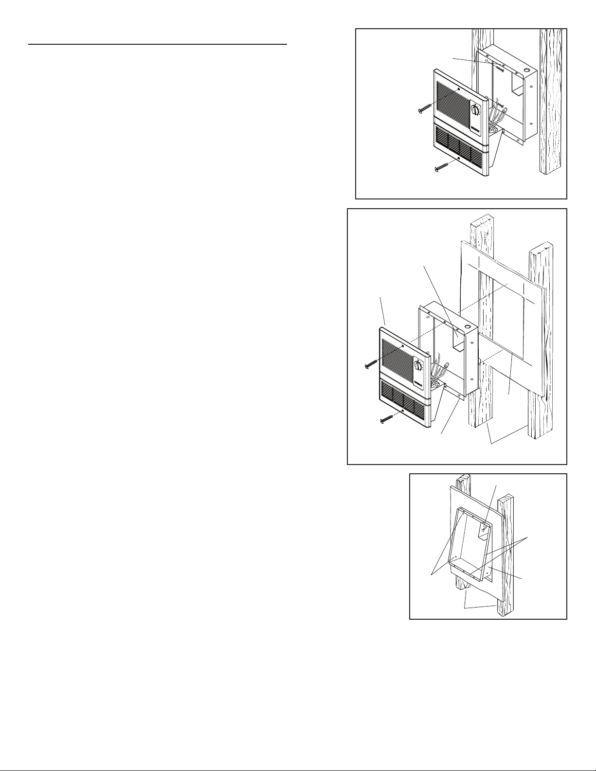
MOUNTING THE HOUSING
(New Construction)
Refer to Figure 1.
1. Choose heater location. Make sure the heater will not be
mounted closer than 12” from a vertical surface or 6”
from
the floor.
2. Using nails or screws, mount one side of housing to wall
stud. The flange must be flush to the stud.
3. Run wiring from circuit breaker or fuse box to heater
location.
4. Install box connector into wiring entrance hole in housing’s
junction box.
5. Pull wiring through entrance hole and secure cable to box
connector. Allow 6” of wiring to make connections.
6. Finished wall opening should be 125/8” high x 105/8” wide.
“B” UNIT MOUNTING HOLE
- TOP AND BOTTOM
EXISTING
CONSTRUCTION
JUNCTION BOX
HEATER ASSMBLY
←
10
5
/
FIGURE 1
8
”
→
←
12
5
/
8
”
→
MOUNTING THE HOUSING
(Existing Construction)
1. Choose heater location. Make sure the heater will not be
mounted closer than 12” from a vertical surface or 6” from
the floor.
2. Refer to Figure 2. Make wall cutout next to a wall stud.
Cutout size: 125/8” high x 105/8” wide.with frame.)
3. Run wiring from circuit breaker or fuse box to heater
location.
4. Install box connector into wiring entrance hole in housing’s
junction box.
5. Pull wiring through cutout and secure cable to box
connector. Allow 6” of wiring to make connections.
6. Refer to Figure 3. Insert TOP of housing into cutout first
so that box connector clears the wall. Then, insert bottom
of housing into cutout. The flange must be flush with the
wall.
7. Use nails or screws to mount one side of housing to wall
stud.
ROUGH-IN FRAME
MOUNTING
HOLES
WALL STUDS
WALL
CUTOUT
WALL STUDS
FIGURE 2
JUNCTION BOX
FLANGE
ROUGH-IN
BOX
FIGURE 3
2
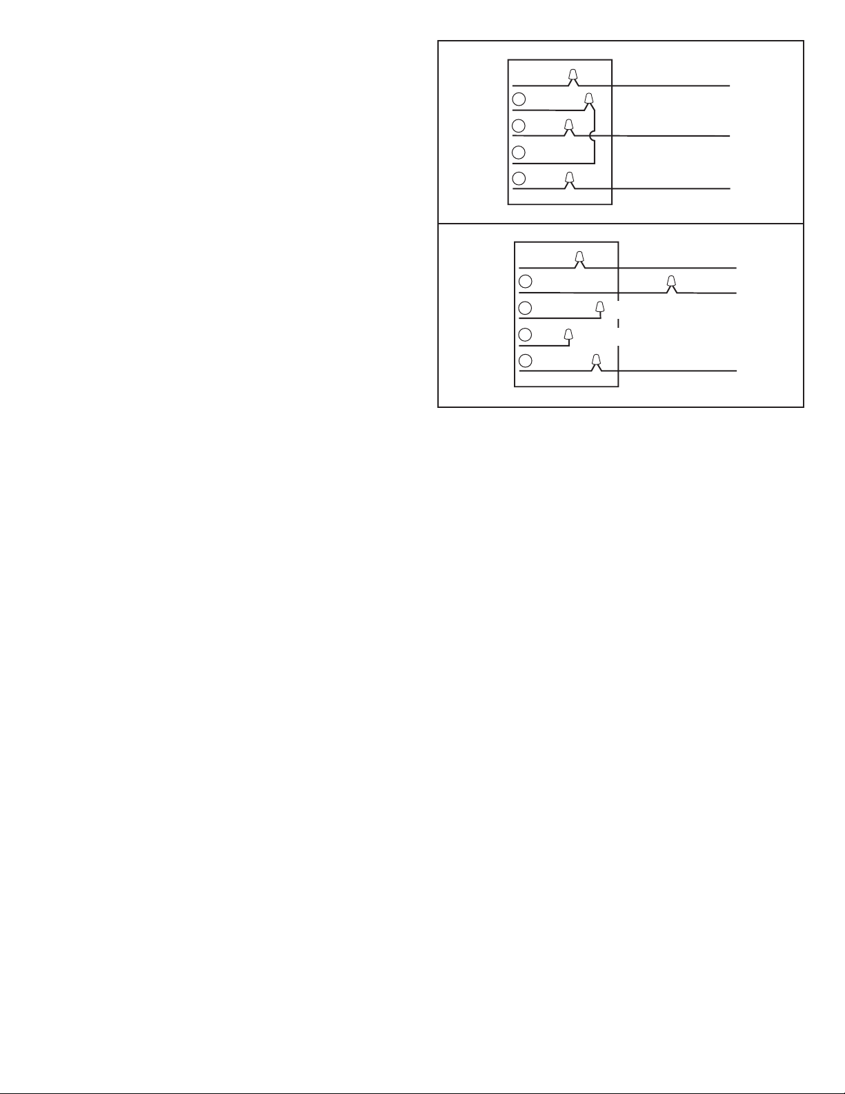
WIRING CONNECTIONS
Installation work and electrical wiring must be done by a
qualified person(s) in accordance with all applicable codes
and standards, including fire-rated construction codes and
standards.
1. While making wiring connections, support the heater
assembly on the bottom of the rough-in frame.
2. For 120 Volt operation, make wiring connections as shown
in Figure 4.
3. For 240 Volt operation, make wiring connections as shown
in Figure 5.
4. Use wire nuts to make connections. Insulate all
connections with electrical tape.
SECURING THE HEATER
1. Dress all wiring back to into junction box.
2. Locate center holes in housing flange and align with
mounting holes in grille.
3. Use two provided screws to attach grille to housing.
120vAC
240vAC
GREEN
GROUND
4
YELLOW
3
WHITE
2
RED
1
BLACK
GREEN
GROUND
4
YELLOW
3
2
1
WHITE
RED
BLACK
NO
CONNECTION
NO
CONNECTION
GREEN OR BARE
GROUND
WHITE
BLACK
GREEN OR BARE
GROUND
RED OR WHITE
BLACK
120vAC
60HZ
FIGURE 4
240vAC
60HZ
FIGURE 5
3

OPERATION
Turn thermostat fully clockwise to HIGH position. Allow heater
to run until room is at desired temperature. Adjust thermostat
as required to maintain desired temperature. Turn the
thermostat to FULL COUNTERCLOCKWISE position when
operation is no longer desired.
Thermal protector: If for any reason temperatures increase
beyond normal limits, a safety thermal fuse will shut heater
off. The heater will require servicing by a qualified electrician.
Check entire installation to determine cause of
overheating.
4

MAINTENANCE
The following maintenance and cleaning tasks can be performed by the user. All other servicing must be performed by
an authorized technician If you have any questions, please
consult with our customer service department at: 800-558-1711.
LUBRICATION
The heater is permanently lubricated and never needs oiling
or disassembly.
CLEANING
Clean heater once a month as follows:
1. Turn off power at service panel.
2. Make sure heating element is cool.
3. Use a soft brush attachment to gently vacuum grille open-
ings or wipe grille clean with a soft cloth.
4. Restore power.
CAUTION: METAL AND ELECTRICAL PARTS SHOULD
NEVER BE IMMERSED IN WATER.
5

SERVICE PARTS
WARRANTY
Key No. Part No. Description
1 99111432 Grille
2 99360253 Knob
3 52872039 Grille Screw
4 97018465 Heater Assembly (9810WH)
97018466 Heater Assembly (9815WH)
5 57271000 Thermostat, with Mounting Nut
6 33384000 Thermostat Cover
7 33178000 Blower & Motor
8 98010878 Heat Box
9 35841000 Thermal Fuse
10 99271433 Thermal Protector
8
5
1
3
2
7
6
9
10
4
BROAN-NUTONE ONE YEAR LIMITED WARRANTY
Broan-NuTone warrants to the original consumer purchaser of its
products that such products will be free from defects in materials
or workmanship for a period of one year from the date of original
purchase. THERE ARE NO OTHER WARRANTIES, EXPRESS
OR IMPLIED, INCLUDING, BUT NOT LIMITED TO, IMPLIED
WARRANTIES OF MERCHANTABILITY OR FITNESS FOR A
PARTICULAR PURPOSE.
During this one-year period, Broan-NuTone will, at its option, repair or replace, without charge, any product or part which is found
to be defective under normal use and service.
THIS WARRANTY DOES NOT EXTEND TO FLUORESCENT
LAMP STARTERS, TUBES, HALOGEN AND INCANDESCENT
BULBS, FUSES, FILTERS, DUCTS, ROOF CAPS, WALL CAPS
AND OTHER ACCESSORIES FOR DUCTING. This warranty
does not cover (a) normal maintenance and service or (b) any
products or parts which have been subject to misuse, negligence,
accident, improper maintenance or repair (other than by BroanNuTone), faulty installation or installation contrary to recommended installation instructions.
The duration of any implied warranty is limited to the one-year period as specified for the express warranty. Some states do not allow limitation on how long an implied warranty lasts, so the above
limitation may not apply to you.
BROAN-NUTONE’S OBLIGATION TO REPAIR OR REPLACE,
AT BROAN-NUTONE’S OPTION, SHALL BE THE PURCHASER’S SOLE AND EXCLUSIVE REMEDY UNDER THIS WARRANTY. BROAN-NUTONE SHALL NOT BE LIABLE FOR INCIDENTAL, CONSEQUENTIAL OR SPECIAL DAMAGES ARISING
OUT OF OR IN CONNECTION WITH PRODUCT USE OR PERFORMANCE. Some states do not allow the exclusion or limitation
of incidental or consequential damages, so the above limitation or
exclusion may not apply to you.
This warranty gives you specific legal rights, and you may also
have other rights, which vary from state to state. This warranty
supersedes all prior warranties.
To qualify for warranty service, you must (a) notify Broan-NuTone
at the address or telephone number below, (b) give the model
number and part identification and (c) describe the nature of any
defect in the product or part. At the time of requesting warranty
service, you must present evidence of the original purchase date.
Broan-NuTone LLC
926 W. State Street
Hartford, Wisconsin 53027
www.broan.com 800-558-1711
6
99045152B

Calefactores de pared
SERIES 9810WH, 9815WH
INSTRUCCIONES IMPORTANTES
INSTRUCCIONES DE INSTALACIÓN
¡LEA Y CONSERVE ESTAS INSTRUCCIONES!
LEA TODAS LAS INSTRUCCIONES ANTES DE INSTALAR O USAR
ESTE CALENTADOR.
Para reducir el riesgo de incendios, descargas eléctricas o lesiones
personales, observe las siguientes precauciones:
1. Use la unidad solo de la manera indicada por el fabricante. Si
tiene preguntas, comuníquese con el fabricante a la dirección
o al número telefónico que se incluye en la garantía.
2. Antes de dar servicio a la unidad o de limpiarla, interrumpa el
suministro eléctrico en el panel de servicio y bloquee los medios
de desconexión del servicio para evitar que la electricidad se
reanude accidentalmente. Cuando no sea posible bloquear los
medios de desconexión del servicio, fije firmemente una señal
de advertencia (como una etiqueta) en un lugar visible del panel
de servicio.
3. El trabajo de instalación y el cableado eléctrico deben estar a
cargo de personal capacitado, de acuerdo con todos los códigos
y normas correspondientes, incluidos los códigos y normas de
construcción específicos sobre protección contra incendios.
4. Al cortar o perforar a través de la pared o del cielo raso, tenga
cuidado de no dañar el cableado eléctrico ni otros servicios
ocultos.
5. Este calentador se calienta cuando se usa. Para evitar
quemaduras, no deje que la piel desnuda toque las superficies
calientes. Mantenga materiales combustibles como muebles,
almohadas, ropa de cama, papeles, ropa, etc., así como las
cortinas, por lo menos a 3 pies (0.9 m) de la parte delantera
del calentador.
6. Es necesario tener extremo cuidado cuando se use un
calentador cerca de niños o personas inválidas, y siempre que
el calentador se deje funcionando y sin atención.
7. No haga funcionar ningún calentador después de que presente
una falla. Desconecte la energía eléctrica en el panel de servicio
y pida que un electricista acreditado inspeccione el calentador
antes de volverlo a usar.
8. No lo use en exteriores.
9. Para desconectar el calentador, mueva los controles a la posición
de apagado y desconecte la energía eléctrica al circuito del
calentador en el panel de desconexión principal (o active el
interruptor de desconexión interna, si existe).
10. No inserte ni permita que objetos extraños entren en la abertura
de ventilación o de escape, pues esto puede ocasionar una
descarga eléctrica, un incendio o daños al calentador.
11. Para prevenir un posible incendio, no bloquee la entrada o salida
del aire de ninguna manera.
12. El calentador tiene piezas calientes y que pueden generar arcos
eléctricos o chispas en el interior. No lo use en áreas donde se
use o almacene gasolina, pintura o vapores o líquidos flamables.
13. Use este calentador solamente como se describe en este
manual. Cualquier otro uso no recomendado por el fabricante
puede ocasionar un incendio, una descarga eléctrica o lesiones
a personas.
14. Instale el calentador por lo menos 6 pulg. desde el piso o
cualquier pared adyacente.
15. Para evitar golpe eléctrico: No instale la unidad en una bañera
o recinto de ducha. Nunca coloque un interruptor en un lugar
que pueda ser alcanzado desde una bañera o ducha.
16. Este producto SOLAMENTE instalarse verticalmente en una
pared. No lo monte en ninguna otra posicion.
17. No conecte el calentador a un variador de luz o control de
velocidad.
18. Este producto debe ser conectado a tierra.
GUARDE ESTAS INSTRUCCIONES
INSTRUCCIONES DE
SEGURIDAD
• Lea detenidamente todas las instrucciones y etiquetas del
producto antes de comenzar la instalación.
• El calefactor puede instalarse únicamente en posición vertical.
• Instale el calefactor a una altura no menor de 15 cm (6 pulg.)
del piso acabado.
• No instale el calefactor sobre tinas ni en duchas.
• Una vez instalado, el calefactor debe estar alejado al menos
30 cm
(12 pulg.) de una pared adyacente.
• No obstruya el calefactor (por ejemplo, evite instalarlo debajo de
barras de toallas, detrás de puertas, etc.).
ESPECIFICACIONES
ELÉCTRICAS
NOTA: Consulte la etiqueta de cableado que se encuentra
en la cubierta del calefactor. El calefactor puede conectarse
para funcionar con 120 V o con 240 V y requiere un circuito
separado.
DIMENSIONES DE LA UNIDAD
Cubierta: 31.7 cm (12 ½ pulg.) de alto x 26.7 cm (10 ½ pulg.) de
ancho x 8.6 cm (3
Rejilla: 37.5 cm (14 ¾ pulg.) de alto x 29.4 cm (11 9/
ancho x 2.5 cm (1 pulg.) de profundidad.
Recorte de la pared:
pulg.) de ancho.
7
3
/8 pulg.) de profundidad.
32 cm (12
5
/8
pulg.) de alto x 27 cm (10
16 pulg.) de
5
/8

INSTALACION
ADVERTENCIA: Para reducir el riesgo de incendio, no
almacene ni use gasolina u otros vapores y líquidos
flamables en las cercanías del calentador.
PRECAUCIÓN: Temperatura alta, el riesgo de incendio,
mantenga los cables eléctricos, cortinas, muebles y otros
materiales combustibles por lo menos 3 pies (0,9 m) del frente
del calentador y lejos de la cara y la parte trasera.
MONTAJE DE LA CUBIERTA
(Construcción nueva)
Vea la figura 1.
1. Elija la posición del calefactor. Asegúrese de que el sitio
donde se instalará el calefactor esté alejado al menos
30 cm (12 pulg.) de una
no menor de 15 cm (6 pulg.) del piso.
2. Fije un lado de la cubierta al montante de la pared con
clavos o tornillos. La brida tiene que estar al ras con el
montante.
3. Tienda los cables del interruptor automático de circuitos
o de la caja de fusibles hacia el sitio de instalación del
calefactor.
4. Instale el conector de caja en el orificio de entrada del
cableado de la caja de conexiones de la cubierta.
5. Haga pasar los cables por el orificio de entrada y fije el
cable al conector de caja. Deje unos 15 cm (6 pulg.) de cable
para poder hacer las conexiones.
6. La abertura de pared terminada debe tener las siguientes
dimensiones: 32 cm (125/8 pulg.) de alto x 27 cm (105/8
pulg.) de ancho.
superficie vertical y a una altura
CONSTRUCCIÓN NUEVA
ORIFICIO DE MONTAJE
DE LA UNIDAD “B”: PARTE
SUPERIOR E INFERIOR
CONSTRUCCIÓN
EXISTENTE
CAJA DE CONEXIONES
MONTAJE DEL
CALEFACTOR
←
(10
27 cm
5
/8
pulg.)
FIGURA 1
→
← →
(12
5
32 cm
/8
pulg.)
MONTAJE DE LA CUBIERTA
(Construcción existente)
1. E
lija la posición del calefactor. Asegúrese de que el sitio
donde se instalará el calefactor esté alejado al menos 30
cm (12 pulg.) de una superficie vertical y a una altura no
menor de 15 cm (6 pulg.) del piso.
2. Vea la figura 2. Haga el recorte de la pared al lado de
un montante de la pared. Tamaño del recorte: 32 cm
(125/8 pulg.) de alto x 27 cm (105/8 pulg.) de ancho con el
armazón.
3. Tienda los cables del interruptor automático de circuitos o
de la caja de fusibles al sitio de instalación del calefactor.
4. Instale el conector de la caja en el orificio de entrada del
cableado de la caja de conexiones de la cubierta.
5. Haga pasar los cables por el recorte y fije el cable al
conector de caja. Deje unos 15 cm (6 pulg.) de cable para
poder hacer las conexiones.
6. Vea la figura 3. Inserte primero la PARTE SUPERIOR de
la cubierta en el recorte, de manera que el conector puede
pasar por la pared. Luego inserte la parte inferior de la
cubierta en el recorte.
La brida tiene que estar al ras con la pared.
7. Fije un lado de la cubierta al montante de la pared con
clavos o tornillos.
RECORTE
DE LA
PARED
ARMAZÓN DE
MONTAJE EN PARED
ORIFICIOS
DE MONTAJE
MONTANTES DE PARED
MONTANTES
DE PARED
CAJA DE CONEXIONES
FIGURA 2
BRIDA
CAJA DE
MONTAJE
EN PARED
FIGURA 3
8

CONEXIONES DE LOS CABLES
El trabajo de instalación y el cableado eléctrico deben estar
a cargo de personal capacitado, de acuerdo con todos los
códigos y normas correspondientes, incluidos los códigos y
normas de construcción específicos sobre protección contra
incendios.
1. Al hacer las conexiones eléctricas, apoye el montaje del
calefactor en la parte inferior de la armazón empotrada.
2. Para el funcionamiento con 120 V, haga las conexiones
indicadas en la figura 4.
3. Para el funcionamiento con 240 V, haga las conexiones
indicadas en la figura 5.
4. Haga las conexiones con tuercas de alambre. Aísle todas
las conexiones con cinta eléctrica.
120 V CA
240 V CA
CABLE DE
TIERRA VERDE
4
AMARILLO
3
BLANCO
2
ROJO
1
NEGRO
CABLE DE
TIERRA VERDE
4
AMARILLO
CABLE DE TIERRA
VERDE O DESNUDO
BLANCO
NEGRO
CABLE DE TIERRA
VERDE O DESNUDO
ROJO O BLANCO
120 V CA
60 Hz
FIGURA 4
FIJACIÓN DEL CALEFACTOR
1. Empuje y arregle todos los cables de vuelta hacia la caja
de conexiones.
2. Ubique los orificios centrales en la brida de la cubierta y
alinéelos con los orificios de montaje de la rejilla.
3. Sujete la rejilla a la cubierta con los dos tornillos
suministrados.
3
2
1
BLANCO
ROJO
NEGRO
SIN CONEXIÓN
SIN CONEXIÓN
NEGRO
240 V CA
60 Hz
FIGURA 5
9

FUNCIONAMIENTO
Gire el termostato completamente en sentido de las agujas
del reloj
a la posición alta (HIGH). Déjelo funcionar hasta que la
habitación llegue a la temperatura deseada. Ajuste el
termostato de ser necesario para mantener la temperatura
deseada. Para detener el funcionamiento del termostato,
gírelo a la posición TOTALMENTE
EN SENTIDO CONTRARIO A LAS AGUJAS DEL RELOJ.
Protector térmico: Si por cualquier motivo la temperatura
sobrepasa los límites normales, un fusible térmico de
seguridad apagará el calefactor.
En ese caso, un electricista calificado deberá examinar el
calefactor.
Inspeccione la instalación completa para determinar la
causa del sobrecalentamiento.
10

MAINTENIMIENTO
El usuario puede realizar las siguientes tareas de
mantenimiento y limpieza. Todos los demás servicios los debe
realizar un técnico autorizado. Si tiene preguntas, consulte a
nuestro departamento de servicio al cliente llamando al: 800558- 1711.
LUBRICACIÓN
El calentador está permanentemente lubricado y nunca
necesitará ponerle aceite ni desarmarlo.
LIMPIEZA
Limpie el calentador una vez al mes tal como sigue:
1. Apague la energía eléctrica en el panel de servicio.
2. Asegúrese de que el elemento de calefacción esté frío.
3. Use un aditamento de cepillo suave para aspirar suave-
mente aberturas de la rejilla o limpie la rejilla con un paño
suave.
4. Restaure la energía eléctrica.
CUIDADO – LAS PIEZAS METALICAS Y ELECTRICAS
NUNCA SE DEBEN SUMERGIR EN AGUA.
11

PIEZAS DE REPUESTO
GARANTÍA
Clave n.º Pieza n.º Descripción
1 99111432 Rejilla
2 99360253 Perilla
3 52872039 Tornillo de la rejilla
4 97018465 Montaje del calefactor (9810WH)
97018466 Montaje del calefactor (9815WH)
5 57271000
Termostato, con tuerca de montaje
6 33384000 Cubierta del termostato
7 33178000 Ventilador y motor
8 98010878 Caja del calefactor
9 35841000 Fusible térmico
10 99271433 Protector térmico
8
5
1
3
2
7
9
10
6
4
GARANTÍA BROAN-NUTONE LIMITADA POR UN AÑO
Broan-NuTone garantiza al consumidor comprador original de sus
productos que dichos productos carecerán de defectos en materiales
o en mano de obra por un período de un año a partir de la fecha
original de compra. NO EXISTEN OTRAS GARANTÍAS, EXPLICITAS O
IMPLÍCITAS, INCLUYENDO, ENTRE OTRAS, GARANTÍAS IMPLÍCITAS
DE COMERCIALIZACIÓN O APTITUD PARA UN PROPÓSITO
PARTICULAR.
Durante el período de un año, y a su propio criterio, Broan-NuTone
reparará o reemplazará, sin costo alguno, cualquier producto o pieza que
se encuentre defectuosa bajo condiciones normales de servicio y uso.
LA PRESENTE GARANTÍA NO CUBRE LOS TUBOS FLUORESCENTES
NI SUS ARRANCADORES, BOMBILLAS DE HALÓGENO E
INCANDESCENTES, FUSIBLES, FILTROS, CONDUCTOS, TAPONES
DE TECHO O PAREDES Y DEMÁS ACCESORIOS PARA CONDUCTOS.
Esta garantía no cubre (a) mantenimiento y servicio normales o (b)
cualesquiera productos o piezas que hayan sido utilizados de forma
errónea, negligente, que hayan causado un accidente, o que hayan sido
reparados o mantenidos inapropiadamente (por otras compañías que no
sean Broan-NuTone), instalación defectuosa, o instalación contraria a las
instrucciones de instalación recomendadas.
La duración de cualquier garantía implícita se limita a un período de
un año como se especifica en la garantía expresa. Algunos estados no
permiten limitaciones en cuanto al tiempo de vencimiento de una garantía
implícita, por lo que la limitación antes mencionada puede no aplicarse
a usted.
LA OBLIGACIÓN DE BROAN-NUTONE DE REPARAR O REEMPLAZAR,
SIGUIENDO EL CRITERIO DE BROAN-NUTONE, DEBERÁ SER EL
ÚNICO Y EXCLUSIVO RECURSO LEGAL DEL COMPRADOR BAJO
ESTA GARANTÍA. BROAN-NUTONE NO SERÁ RESPONSABLE
POR DAÑOS INCIDENTALES, CONSECUENTES, O POR DAÑOS
ESPECIALES QUE SURJAN A RAÍZ DEL USO O DESEMPEÑO DEL
PRODUCTO. Algunos estados no permiten la exclusión o limitación
de daños incidentales o consecuentes, por lo que la limitación antes
mencionada puede no aplicarse a usted.
Esta garantía le proporciona derechos legales específicos, y usted puede
también tener otros derechos, los cuales varían de estado a estado. Esta
garantía reemplaza todas las garantías anteriores.
Para calificar para la garantía de servicio, usted debe (a) notificar a
Broan-NuTone al domicilio o al número de teléfono que se menciona
abajo, (b) dar el número del modelo y la identificación de la pieza, y (c)
describir la naturaleza de cualquier defecto en el producto o la pieza. En
el momento de solicitar servicio cubierto por la garantía, usted debe de
presentar un comprobante con la fecha original de compra.
Broan-NuTone LLC, 926 W. State Street, Hartford, Wisconsin 53027
www.broan.com 800-558-1711
12
99045152B
 Loading...