


® |
® |
PR3000 Home Gym
Assembly Manual
Nautilus® |
Bowflex® |
Schwinn® Fitness |
StairMaster® |
Universal® |
Nautilus Institute® |
001-7279-063008A

Table of Contents
Before Assembly...................................................................... |
2 |
Tools........................................................................................... |
2 |
Important Safety Instructions................................................ |
3 |
Hardware................................................................................... |
4 |
Parts............................................................................................ |
5 |
Assembly................................................................................... |
6 |
Assemble the Base........................................................... |
6 |
Attach the Rod Pack......................................................... |
7 |
Attach the Lower Lat Assembly...................................... |
8 |
Attach the Seat Support Rail........................................... |
9 |
Attach Pulley Arms......................................................... |
10 |
Attach the Seat Bottom to the Seat Backbone.......... |
11 |
Attach Leg Extension Assembly................................... |
12 |
Attach Seat Back............................................................ |
13 |
Attach the Lat Crossbar with Pulleys ............................................ |
14 |
Attach the Rear Lat Cross Bar...................................... |
15 |
Attach the Upper Lat Tower Assembly........................ |
16 |
Attach the Lat Pulley Housing....................................... |
17 |
Cable and Pulley Routing............................................... |
18 |
Connect the Rod Cables................................................. |
19 |
Connect the Right Cable................................................ |
20 |
Leg Extension Cable Routing......................................... |
21 |
Final Inspection............................................................... |
21 |
Contacts................................................................................... |
23 |
Before Assembly
Select where you are going to locate your Bowflex® home gym carefully. The best location is on a hard, level surface. For best results, assemble your home gym in the location where you intend to use it. For safe operation, allow a workout area of at least 100” x 78” (2.6m x 2.0m) of free space.
Follow these basic tips to make your assembly quick and easy.
1.Gather all the pieces you need for each step.
2.Turn all the bolts and locknuts toward the right to tighten. Turn towards the left to loosen.
3.Use a combination wrench to grip the locknut when you tighten a bolt that has a locknut to make sure it is tight.
4.All of the tools needed for assembly are included with the unit. You may find the use of a utility knife or scissors beneficial during the unpacking and assembly process.
5.When attaching two pieces, lightly lift and look through the bolt holes to help guide the bolt through the holes.
6.Assembly requires two people.
NOTICE: Leave all of the cables wrapped and bagged until the Bowflex® home gym is completely assembled.
Tools
•(2) Adjustable Wrenches (not included)
•Phillips Head Screwdriver
2
Assembly Manual

Important Safety Instructions
 This icon means a potentially hazardous situation which, if not avoided, could result in death or serious injury.
Before using this equipment, obey the following warnings
Read and understand all warnings on this machine.
Carefully read and understand the Assembly Manual.
•Keep bystanders and children away from the product you are assembling at all times.
•Do not assemble equipment in a wet or damp location.
•Make sure assembly is done in an appropriate work space away from foot traffic and exposure to bystanders.
•Some components of the machine can be heavy or awkward. Use a second person when doing the assembly steps involving these parts. Do not do steps that involve heavy lifting or awkward movements on your own.
•Do not try to change the design or functionality of this machine. This could compromise the safety and can void the warranty.
•If replacement parts are necessary use only genuine Nautilus® replacement parts and hardware. Failure to use genuine replacement parts can cause a risk to users, keep the machine from operating correctly or void the warranty.
•Do not use or put the machine into service until the machine has been fully assembled and inspected for correct performance in accordance with the Owner’s Manual.
3
Assembly Manual
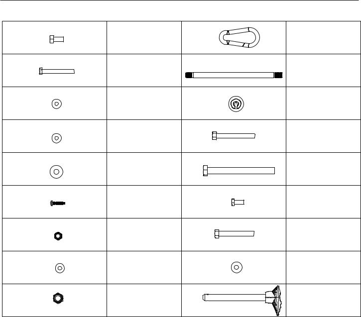
Hardware
(Hardware not actual size)
Qty. 19
Qty. 2
Qty. 3
Qty. 4
Qty. 31
Qty. 3
Qty. 6
Qty. 4
Qty. 6
Item #1 |
Qty. 6 |
Item #10 |
3/8”x 3/4” Hex Head |
|
|
|
Snap Hook |
|
Bolt |
|
|
|
|
|
Item #2 |
Qty. 2 |
Item #11 |
5/16”x 2 1/2” Hex Head |
|
1/2” x 9 1/2” Threaded |
Bolt |
|
Stud |
Item #3 |
Qty. 4 |
Item #12 |
|
||
1/4” Washer |
|
Ball Stop |
Item #4 |
Qty. 2 |
Item #13 |
|
||
1/2” Washer |
|
3/8” x 3” Hex Head Bolt |
Item #5 |
Qty. 2 |
Item #14 |
|
1/2” x 5 1/4” Hex Head |
|
3/8” Washer |
|
|
|
Bolt |
|
|
|
|
Item #6 |
Qty. 4 |
Item #15 |
#10 x 1” Phillips Head |
|
5/16” x 3/4” Hex Head |
Screw |
|
Bolt |
Item #7 |
Qty. 4 |
Item #16 |
|
3/8” x 2 3/4” Hex Head |
|
3/8” Nylock Nut |
|
|
|
Bolt |
|
|
|
|
Item #8 |
Qty. 6 |
Item #17 |
|
||
1/2” Wide Washer |
|
5/16” Washer |
Item #9 |
Qty. 1 |
Item #18 |
|
||
1/2” Nylock Nut |
|
Seat Pin |
4
Assembly Manual

Parts
47 |
51 |
44 |
52 |
41 |
42 |
43 |
|
26 |
25 |
|
|
|
|
||||||
|
|
|
|
|
|
|
24 |
|
|
49 |
|
|
|
46 |
|
|
40 |
|
36 |
48 |
|
|
|
|
27 |
|
|||
|
|
|
|
|
|
|
|
||
|
|
|
|
|
|
|
|
|
|
50 |
|
|
|
|
|
31 |
|
|
|
|
|
|
45 |
|
|
|
|
35 |
29 |
|
|
|
|
|
33 |
|
|
|
|
|
|
|
|
|
34 |
|
|
|
|
|
|
|
|
|
|
|
|
|
|
|
|
|
32 |
|
|
|
|
30 |
28 |
|
|
|
|
|
|
|
|
||
|
39 |
|
|
|
|
|
20 |
|
22 |
|
|
|
|
|
|
|
|
||
|
|
|
|
|
|
|
|
|
|
|
|
|
38 |
|
|
|
|
23 |
|
|
|
|
|
|
|
|
|
|
|
|
|
|
|
|
37 |
|
|
|
21 |
|
|
|
|
|
19 |
|
|
|
|
|
|
|
|
|
|
|
|
|
Item # |
Qty. |
Description |
|
|
|
19 |
1 |
Base Platform |
20 |
1 |
Right Frame Rail |
21 |
1 |
Left Frame Rail |
22 |
1 |
Rear Cross Bar |
23 |
1 |
Central Support |
24 |
1 |
Lat Cross Bar with Pulleys |
25 |
1 |
Rear Lat Cross Bar |
26 |
1 |
Upper Lat Tower |
27 |
1 |
Right Pulley Arm |
28 |
1 |
Left Pulley Arm |
29 |
1 |
Rod Pack |
30 |
1 |
Lower Lat Tower |
31 |
1 |
Seat Back |
32 |
1 |
Seat Backbone |
33 |
1 |
Seat Bottom |
34 |
1 |
Seat Support Rail |
35 |
2 |
Floating Pulleys |
Item # |
Qty. |
Description |
|
|
|
36 |
1 |
Lat Pulley Housing |
37 |
1 |
Leg Extension Assembly |
38 |
2 |
Roller Tubes |
39 |
4 |
Foam Roller Pads |
40 |
1 |
Placard |
41 |
1 |
Rod Pack Strap |
42 |
2 |
Adjustable Handgrips |
43 |
2 |
Handgrips |
44 |
1 |
Accessory Bag #1 |
45 |
2 |
Leg Press Extension Cables |
46 |
1 |
Snap Hook |
47 |
1 |
Accessory Bag #2 |
48 |
4 |
Roller End Caps |
49 |
1 |
Leg Extension Lock Pin |
50 |
1 |
Seat Backbone Lock Pin |
51 |
1 |
Hardware Bag |
52 |
1 |
Manual Kit |
5
Assembly Manual
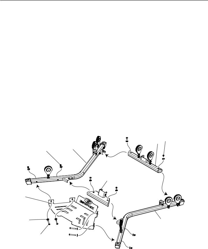
Assembly
Step 1: Assemble the Base
Parts
•Base Platform (#19)
•Right Frame Rail (#20)
•Left Frame Rail (#21)
•Rear Cross Bar (#22)
•Central Support (#23)
Hardware
•(4) 3/8” x 3/4” Hex Head Bolts (#1)
•(4) 3/8” x 2 3/4” Hex Head Bolts (#16)
•(12) 3/8” Washers (#5)
•(4) 3/8” Nylock Nuts (#7)
Tools
•Adjustable Wrench (not included)
1-1 Put the Base Assembly parts on the floor.
1-2 Align the bolt holes on the Right and Left Frame Rails with the holes in the Base Platform, Rear Cross Bar and the Central Support.
1-3 Install the hardware, but do not tighten the bolts. 1-4 Tighten all hardware.
22 1
7 20
23
19
5 |
21 |
|
16
6
Assembly Manual

Assembly
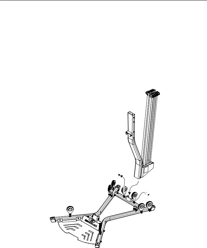
Step 2: Attach the Rod Pack
Parts
•Rod Pack (#29)
•Lower Lat Tower (#30)
•Rod Pack Strap (#41)
Hardware
•(3) #10 x 1” Phillips Head Screws (#6)
•(3) 1/4” Washers (#3)
Tools
•Phillips Head Screw Driver (not included)
2-1 Slide the Rod Pack into the Lower Lat Tower. 2-2 Install and tighten the hardware.
30
41
29
 3
3
6
7
Assembly Manual
Assembly
Step 3: Attach the Lower Lat Assembly to the Base Assembly
Parts
•Competed Assembly (from step 1)
•Lower Lat Tower Assembly (from step 2)
Hardware
•(2) 3/8” x 3/4” Hex Head Bolts (#1)
•(2) 3/8” Washers (#5)
Tools
•Adjustable Wrench (not included)
3-1 Put the Lower Lat Tower Assembly onto the Completed Assembly. 3-2 Install and tighten the hardware.
5


 1
1
8
Assembly Manual
 Loading...