


EHF1838K & LHF2025K
ENGINEERED FLOORING STAPLERS
ENGRAPADORASPARA DUELA DE INGENIERÍA AGRAFEUSESÀ PLANCHER PROFESSIONNELLES
OPERATION and MAINTENANCE MANUAL MANUAL DE OPERACIÓN Y DE MANTENIMIENTO MANUEL D’INSTRUCTIONS ET D’ENTRETIEN
BEFORE OPERATING THIS TOOL, ALL OPERATORS SHOULD STUDY THIS MANUAL TO UNDERSTAND AND FOLLOW THE SAFETY WARNINGS AND INSTRUCTIONS. KEEP THESE INSTRUCTIONS WITH THE TOOL FOR FUTURE REFERENCE. IF YOU HAVE ANY QUESTIONS, CONTACT YOUR BOSTITCH REPRESENTATIVEOR DISTRIBUTOR.
ANTES DE OPERAR ESTA HERRAMIENTA, TODOS LOS OPERADORES DEBERÁN ESTUDIAR ESTE MANUAL PARA PODER COMPRENDER Y SEGUIR LAS ADVERTENCIAS SOBRE SEGURIDAD Y LAS INSTRUCCIONES. MANTENGA ESTAS INSTRUCCIONES CON LA HERRAMIENTA PARA FUTURA REFERENCIA, SI TIENE ALGUNA DUDA, COMUNÍQUESE CON SU REPRESENTANTE DE BOSTITCH O CON SU DISTRIBUIDOR.
LIRE ATTENTIVEMENT LE PRÉSENT MANUEL AVANT D’UTILISER L’APPAREIL.PRÉTER UNE ATTENTION TOUTE PARTICULIÈRE AUX CONSIGNES DE SÉCURITÉ ET AUX AVERTISSEMENTS. GARDER CE MANUEL AVEC L’OUTIL POUR FUTUR RÉFÉRENCE. SI VOUS AVEZ DES QUESTIONS, CONTACTEZ VOTRE REPRÉSENTANT OU VOTRE CONCESSIONNAIRE BOSTITCH.
STANLEY FASTENING SYSTEMS L.P.
189854REVA 11/09

INTRODUCTION
The Bostitch EHF1838K & LHF2025K are precision-built tools, designed for high speed, high volume fastening. These tools will deliver efficient, dependable service when used correctly and with care. As with any fine power tool, for best performance the manufacturer’s instructions must be followed. Please study this manual before operating the tool and understand the safety warnings and cautions. The instructions on installation, operation and maintenance should be read carefully, and the manuals kept for reference. NOTE: Additional safety measures may be required because of your particular application of the tool. Contact your Bostitch representative or distributor with any questions concerning the tool and its use. Bostitch, Inc., East Greenwich, Rhode Island 02818.
INDEX
Safety Instructions . . . . . . . . . . . . . . . . . . . . . . . . . . . . . . . . . . . . . . . . . . . . . 3
Tool Components . . . . . . . . . . . . . . . . . . . . . . . . . . . . . . . . . . . . . . . . . . . . . . . 4
Tool/Fastener Specifications . . . . . . . . . . . . . . . . . . . . . . . . . . . . . . . . . . . . . . 5
Air Supply and Connections. . . . . . . . . . . . . . . . . . . . . . . . . . . . . . . . . . . . . . . 6
Loading the Tool. . . . . . . . . . . . . . . . . . . . . . . . . . . . . . . . . . . . . . . . . . . . . . . . 7
Tool Operation . . . . . . . . . . . . . . . . . . . . . . . . . . . . . . . . . . . . . . . . . . . . . . . . . 8
Tool Operation Check. . . . . . . . . . . . . . . . . . . . . . . . . . . . . . . . . . . . . . . . . . . . 9
Maintaining the Pneumatic Tool . . . . . . . . . . . . . . . . . . . . . . . . . . . . . . . . . . . 9
Troubleshooting . . . . . . . . . . . . . . . . . . . . . . . . . . . . . . . . . . . . . . . . . . . . . . 10
Maintenance Checklist . . . . . . . . . . . . . . . . . . . . . . . . . . . . . . . . . . . . . . . . . . 11
Other Bostitch Flooring Products. . . . . . . . . . . . . . . . . . . . . . . . . . . . . . . . . . 12
NOTE:
Bostitch tools have been engineered to provide excellent customer satisfaction and are designed to achieve maximum performance when used with precision Bostitch fasteners engineered to the same exacting standards. Bostitch cannot assume responsibility for product performance if our tools are used with fasteners or accessories not meeting the specific requirements established for genuine Bostitch nails, staples and accessories.
 ™
™
®
LIMITED WARRANTY — U.S. and Canada Only
Effective December 1, 2005 Bostitch, L.P. warrants to the originalretail purchaser that the productpurchasedis free from defectsin material and workmanship,and agreesto repairor replace, at Bostitch’soption,any defectiveBostitch brandedpneumatic stapler or nailer for a periodof seven(7) yearsfrom date of purchase (one (1) year from the date of purchase for compressorsand tools usedin productionapplications).Warrantyis not transferable.Proofof purchase date required.This warranty covers only damageresulting from defects in materialor workmanship;it does not cover conditionsor malfunctionsresulting from normalwear,neglect,abuse, accidentor repairsattemptedor madeby other than our nationalrepair center or authorized warrantyservice centers. Driver blades,bumpers,o-rings,pistons and piston rings are considerednormallywearingparts.For optimal performance of yourBostitch tool alwaysuse genuine Bostitch fastenersand replacementparts.
THIS WARRANTY IS IN LIEU OF ALL OTHER WARRANTIES, EXPRESS OR IMPLIED,INCLUDINGBUT NOT LIMITEDTOTHEIMPLIEDWARRANTIES OF MERCHANTABILITYOR FITNESSFOR A PARTICULARPURPOSE. BOSTITCH SHALL NOT BE LIABLE FOR ANY INCIDENTAL OR CONSEQUENTIAL DAMAGES.
Some states and countriesdo not allow limitationson how long an implied warrantylasts,or the exclusion or limitation of incidental or consequential damages, so the above limitationsor exclusions may not apply to you.This warranty gives you specificlegalrights,and youmayalsohaveotherrights whichvary from stateto stateand countryto country.
Toobtain warranty servicein the U.S.return the product, togetherwith proof of purchase,to the U.S.BostitchNational or Regional IndependentAuthorized WarrantyService Center.In the U.S. you may call us at 1-800-556-6696or visit www.BOSTITCH.com for the location most convenientfor you. In Canada please call us at 800-567-7705or visit www.BOSTITCH.com
-2-

SAFETY INSTRUCTIONS
EYE PROTECTION which conforms to ANSI specifications and provides protection against flying particles both from the FRONT and SIDE should ALWAYS be worn by the operator and others in the work area when connecting to air supply, loading, operating or servicing this tool. Eye protection is required to guard against flying fasteners and debris, which could cause severe eye injury.
The employer and/or user must ensure that proper eye protection is worn. Eye protection equipment must conform to the requirements of the American National Standards Institute, ANSI Z87.1 and provide both frontal and side protection. NOTE: Non-side shielded spectacles and face shields alone do not provide adequate protection.
CAUTION: Additional Safety Protection will be required in some environments. For example, the working area may include exposure to noise level which can lead to hearing damage. The employer and user must ensure that any necessary hearing protection is provided and used by the operator and others in the work area. Some environments will require the use of head protection equipment. When required, the employer and user must ensure that head protection conforming to ANSI Z89.1 is used.
AIR SUPPLY AND CONNECTIONS
Do not use oxygen, combustible gases, or bottled gases as a power source for this tool as tool may explode, possibly causing injury.
Do not use supply sources which can potentially exceed 200 P.S.I.G. as tool may burst, possibly causing injury.
The connector on the tool must not hold pressure when air supply is disconnected. If a wrong fitting is used, the tool can remain charged with air after disconnecting and thus will be able to drive a fastener even after the air line is disconnected possibly causing injury.
Do not pull trigger or depress contact arm while connected to the air supply as the tool may cycle, possibly causing injury.
Always disconnect air supply: 1.) Before making adjustments; 2.) When servicing the tool; 3.)When clearing a jam; 4.)When tool is not in use; 5.)When moving to a different work area, as accidental actuation may occur, possibly causing injury.
LOADINGTOOL
When loading tool: 1.) Never place a hand or any part of body in fastener discharge area of tool; 2.) Never point tool at anyone; 3.) Do not pull the trigger or depress the trip as accidental actuation may occur, possibly causing injury.
OPERATION
Always handle the tool with care: 1.) Never engage in horseplay; 2.) Never pull the trigger unless nose is directed toward the work; 3.) Keep others a safe distance from the tool while tool is in operation as accidental actuation may occur,possibly causing injury.
The operator must not hold the trigger pulled on contact arm tools except during fastening operation as serious injury could result if the trip accidentally contacted someone or something, causing the tool to cycle.
Keep hands and body away from the discharge area of the tool. A contact arm tool may bounce from the recoil of driving a fastener and an unwanted second fastener may be driven possibly causing injury.
Check operation of the contact arm mechanism frequently. Do not use the tool if the arm is not working correctly as accidental driving of a fastener may result. Do not interfere with the proper operation of the contact arm mechanism.
Do not drive fasteners on top of other fasteners or with the tool at an overly steep angle as this may cause deflection of fasteners which could cause injury.
Do not drive fasteners close to the edge of the work piece as the wood may split, allowing the fastener to be deflected possibly causing injury.
This nailerproducesSPARKSduringoperation. NEVERuse the nailernearflammablesubstances, gases or vapors including lacquer, paint, benzine, thinner,gasoline, adhesives, mastics, glues or any other material that is -- or the vapors, fumes or by-products of which are -- flammable, combustible or explosive. Using the nailer in any such environment could cause an EXPLOSION resulting in personal injury or death to user and bystanders.
MAINTAININGTHETOOL
When working on air tools note the warnings in this manual and use extra care when evaluating problem tools.
-3-
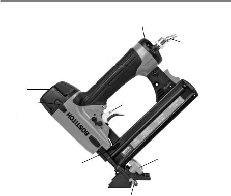
TOOL COMPONENTS
Rear Exhaust
Swivel Air Fitting
Over-Molded
Comfort Grip
Magazine
 Release Button
Frame Cap
Frame Protector |
Trigger |
Frame
Trigger Lockout 
Adjustable Precision Knobs
Reload Indicator
Easy-Sight Tongue
Engagement
-4-

TOOL SPECIFICATIONS
All dimensions in inches unless otherwise specified.
|
EHF1838K |
LHF2025K |
Description |
18ga Flooring Stapler |
20ga Flooring Stapler |
Engine Type |
Oil-Free |
Oil-Free |
Operation Pressure Range |
70-120 PSI (4.9 to 8.43kg/cm2) |
70-120 PSI (4.9 to 8.43 kg/cm2) |
Maximum Operation Pressure |
120 PSI (8.43 kg/cm2) |
120 PSI (8.43 kg/cm2) |
Fastener Type |
SX5035 Series |
SB97-1GLS |
Fastener Gauge |
18 Gauge |
20 Gauge |
Fastener Range |
1” - 1-1/2” (25mm - 38mm) |
1” (25mm) |
|
|
|
Magazine Capacity |
100 |
125 |
Length |
9-1/4” (235mm) |
9-1/4” (235mm) |
Width |
2-3/4” (69.9mm) |
2-3/4” (69.9mm) |
Height |
9-7/8” (250.8mm) |
8.5” (215.9mm) |
Weight |
3.47lbs. (1.57kg) |
2.9lbs. (1.32kg) |
Operating Pressure:
70 to 120 p.s.i.g. (4.9 to 8.43 kg/cm2). Select the operating pressure within in this range for best fastener performance.
DO NOT EXCEED THIS RECOMMENDED OPERATING PRESSURE.
Air Consumption:
The EHF1838K requires 1.94 cubic feet per minute or C.F.M.(54.93 liters per minute or LT/MIN) of free air at 80PSI (5.6 kg/cm2) to operate at a rate of 60 fasteners per minute. The LHF2025K requires 1.90 cubic feet per minute or C.F.M. (53.8 liters per minute or LT/MIN) of free air at 80PSI (5.6 kg/cm2) to operate at a rate of 60 fasteners per minute. To determine the appropriately sized air compressor, take the actual rate at which the tool will be run and compare the required C.F.M.(LT/MIN) to the compressors free air delivery (C.F.M./ LT/MIN) at 80 PSI (5.6 kg/cm2).
For example, if your fastener usage averages 30 fasteners per minute, you need 50% of the tools C.F.M. required to operate the tool at the rate of 60 fasteners per minute. In this case, be sure that your air compressor can deliver a minimum of 0.97 C.F.M. (27.47 LT/MIN) at 80 PSI (5.6 kg/cm2) for optimum performance.
FASTENER SPECIFICATIONS
Tool Model |
Fastener Type |
Fastener SKU |
Crown Width |
Gauge |
Length |
|
|
SX50351G |
7/32” |
18 |
1” (25mm) |
|
|
SX50351-1/8G |
7/32” |
18 |
1-1/8” (28mm) |
EHF1838K |
|
SX50351-3/16G |
7/32” |
18 |
1-3/16” (30mm) |
|
|
|
|
|
|
|
SX50351-1/4G |
7/32” |
18 |
1-1/4” (32mm) |
|
|
|
||||
|
Staples |
|
|
|
|
|
SX50351-3/8G |
7/32” |
18 |
1-3/8” (35mm) |
|
|
|
SX50351-1/2G |
7/32” |
18 |
1-1/2” (38mm) |
LHF2025K |
Staples |
SB97-1GLS |
3/16” |
20 |
1” (25mm) |
|
|
|
|
|
|
* Stainless steel fasteners also available in certain sizes. Visit www.BOSTITCH.com for further details.
NOTE:
BOSTITCH tools have been engineered to provide superior customer satisfaction and are designed to achieve maximum perfomance when used with precision BOSTITICH fasteners engineered to the same exacting standards. BOSTITCH cannot assume responsibility for product performance if our tools are used with fasteners or accessories not meeting the specific requirements established for genuine BOSTITCH fasteners and accessories.
-5-
AIR SUPPLYAND CONNECTIONS
Do not use oxygen, combustible gases, or bottled gases as a power source for this tool as tool may explode, possibly causing injury.
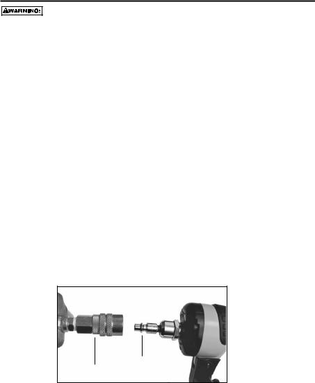
FITTINGS:
Install a male plug on the tool which is free flowing and which will release air pressure from the tool when disconnected from the supply source.
HOSES:
Air hoses should have a minimum of 150 p.s.i. (10.6 kg/cm2) working pressure rating or 150 percent of the maximum pressure that could be produced in the air system. The supply hose should contain a fitting that will provide “quick disconnecting” from the male plug on the tool.
SUPPLY SOURCE:
Use only clean regulated compressed air as a power source for this tool. NEVER USE OXYGEN, COMBUSTIBLE GASES, OR BOTTLED GASES,AS A POWER SOURCE FOR THISTOOL AS TOOLMAYEXPLODE.
REGULATOR:
A pressure regulator with an operating pressure of 0 - 125 p.s.i. (0 - 8.79 kg/cm2) is required to control the operating pressure for safe operation of this tool. Do not connect this tool to air pressure which can potentially exceed 200 p.s.i. (14 kg/cm2) as tool may burst, possibly causing injury.
OPERATING PRESSURE:
Do not exceed recommended maximum operating pressure as tool wear will be greatly increased. The air supply must be capable of maintaining the operating pressure at the tool. Pressure drops in the air supply can reduce the tool’s driving power. Refer to “TOOL SPECIFICATIONS” for setting the correct operating pressure for the tool.
FILTER:
Dirt and water in the air supply are major causes of wear in pneumatic tools. A filter will help to get the best performance and minimum wear from the tool. The filter must have adequate flow capacity for the specific installation. The filter has to be kept clean to be effective in providing clean compressed air to the tool. Consult the manufacturer’s instructions on proper maintenance of your filter. A dirty and clogged filter will cause a pressure drop which will reduce the tool’s performance.
Quick Connect Plug
Quick Disconnect Plug
-6-

LOADINGTHE EHF1838K & LHF2025K
EYE PROTECTION which conforms to ANSI specifications and provides protection against flying particles both from the FRONT and SIDE should ALWAYS be worn by the operator and others in the work area when connecting to air supply, loading, operating or servicing this tool. Eye protection is required to guard against flying fasteners and debris, which could cause severe eye injury.
The employer and/or user must ensure that proper eye protection is worn. Eye protection equipment must conform to the requirements of the American National Standards Institute, ANSI Z87.1 and provide both frontal and side protection. NOTE: Non-side shielded spectacles and face shields alone do not provide adequate protection.
TO PREVENT ACCIDENTAL INJURIES:
•Never place a hand or any other part of the body in fastener discharge area of tool while the air supply is connected.
•Never point the tool at anyone else.
•Never engage in horseplay.
•Never pull the trigger unless nose is directed at the work.
•Always handle the tool with care.
•Do not pull the trigger or depress the trip mechanism while loading the tool.
LOADING THE EHF1838K & LHF2025K
1.Depress magazine release button and pull back magazine.
2.Open magazine fully and turn tool sideways with discharge area pointed away from yourself and others. Load staples in channel.
3.Push magazine forward until latch is engaged.
-7-

TOOL OPERATION
EYE PROTECTION which conforms to ANSI specifications and provides protection against flying particles both from the FRONT and SIDE should ALWAYSbe worn by the operator and others in the work area when connecting to air supply, loading, operating or servicing this tool. Eye protection is required to guard against flying fasteners and debris, which could cause severe eye injury.
The employer and/or user must ensure that proper eye protection is worn. Eye protection equipment must conform to the requirements of the American National Standards Institute, ANSI Z87.1 and provide both frontal and side protection. NOTE: Non-side shielded spectacles and face shields alone do not provide adequate protection.
BEFORE HANDLING OR OPERATING THIS TOOL:
I.READ AND UNDERSTAND THE WARNINGS CONTAINED IN THIS MANUAL.
II.REFER TO “TOOL SPECIFICATIONS” IN THIS MANUALTO IDENTIFY THE OPERATING SYSTEM ON YOURTOOL.
OPERATION
The operator must not hold the trigger pulled on contact trip tools except during fastening operation, as serious injury could result if the trip accidentally contacted someone or something, causing the tool to cycle.
Keep hands and body away from the discharge area of the tool. A contact trip tool may bounce from the recoil of driving a fastener and an unwanted second fastener may be driven, possibly causing injury.
SEQUENTIAL TRIP:
In SEQUENTIAL TRIP MODE the contact trip operates in conjunction with the trigger to drive a fastener. To operate a sequential trip tool, first position the contact trip on the work surface WITHOUT PULLING THE TRIGGER. Depress the contact trip and then pull the trigger to drive a fastener. As long as the contact trip is contacting the work and is held depressed, the tool will drive a fastener each time the trigger is depressed. If the contact trip is allowed to leave the work surface, the sequence described above must be repeated to drive another fastener.
IN ADDITIONTOTHE OTHER WARNINGS CONTAINED INTHIS MANUAL OBSERVETHE FOLLOWING FOR SAFE OPERATION
•Use the BOSTITCH pneumatic tool only for the purpose for which it was designed.
•Never use this tool in a manner that could cause a fastener to be directed toward the user or others in the work area.
•Do not use the tool as a hammer.
•Always carry the tool by the handle. Never carry the tool by the air hose.
•Do not alter or modify this tool from the original design or function without approval from BOSTITCH, INC.
•Always be aware that misuse and improper handling of this tool can cause injury to yourself and others.
•Never clamp or tape the trigger or contact trip in an actuated position.
•Never leave a tool unattended with the air hose attached.
• Do not operate this tool if it does not contain a legible WARNING LABEL.
•Do not continue to use a tool that leaks air or does not function properly.Notify your nearest Bostitch representative if your tool continues to experience functional problems.
-8-

TOOL OPERATION CHECK
CAUTION: Remove all fasteners from tool before performing tool operation check.
SEQUENTIAL TRIP OPERATION:
A.Press the contact trip against the work surface, without touching the trigger.
THE TOOL MUST NOT CYCLE.
B.Hold the tool off the work surface and pull the trigger.
THE TOOL MUST NOT CYCLE.
Release the trigger. The trigger must return to the trigger stop on the frame.
C.Pull the trigger and press the contact trip against the work surface.
THE TOOL MUST NOT CYCLE.
D.With finger off the trigger, press the contact trip against the work surface. Pull the trigger.
THE TOOL MUST CYCLE.
MAINTAININGTHE PNEUMATICTOOL
When working on air tools, note the warnings in this manual and use extra care evaluating problem tools.
CAUTION: Pusher spring (constant force spring). Caution must be used when working with the spring assembly.The spring is wrapped around, but not attached to, a roller. If the spring is extended beyond its length, the end will come off the roller and the spring will roll up with a snap, with a chance of pinching your hand. Also the edges of the spring are very thin and could cut. Care must also be taken to insure no permanent kinks are put in the spring as this will reduce the springs force.
REPLACEMENT PARTS:
Use only genuine BOSTITCH replacement parts. Do not use modified parts.
ASSEMBLY PROCEDURE FOR SEALS:
When repairing a tool, make sure the internal parts are clean and lubricated. Use Parker “O”-LUBE, Magnalube, or equivalent on all “O”-rings. Coat each “O”-ring with lubricant before assembling.
AIR SUPPLY-PRESSURE AND VOLUME:
Air volume is as important as air pressure. The air volume supplied to the tool may be inadequate because of undersize fittings and hoses, or from the effects of dirt and water in the system. Restricted air flow will prevent the tool from receiving an adequate volume of air, even though the pressure reading is high. The results will be slow operation, misfeeds or reduced driving power. Before evaluating tool problems for these symptoms, trace the air supply from the tool to the supply source for restrictive connectors, low points containing water and anything else that would prevent full volume flow of air to the tool.
-9-

TROUBLESHOOTING
PROBLEM
Trigger valve housing leaks air
Trigger valve stem leaks air
Frame/nose leaks air
Frame/cap leaks air
Failure to cycle
Lack of power; slow to cycle
Skipping fasteners; intermittent feed
Fasteners jam in tool
CAUSE |
CORRECTION |
O-ring cut or cracked . . . . . . . . . . . . . . . . . . . .Replace O-ring
O-ring/seals cut or cracked . . . . . . . . . . . . . .Replace trigger valve assembly
O-ring or gasket is cut or cracked . . . . . . . . .Replace O-ring or gasket
Bumper cracked/worn . . . . . . . . . . . . . . . . . . .Replace bumper
Damaged gasket or seal . . . . . . . . . . . . . . . . .Replace gasket or seal
Cracked/worn head valve . . . . . . . . . . . . . . .Replace head valve
Loose cap screws . . . . . . . . . . . . . . . . . . . . . . .Tighten and recheck
Air supply restriction . . . . . . . . . . . . . . . . . . . .Check air supply equipment Worn head valve . . . . . . . . . . . . . . . . . . . . . . .Replace head valve
Broken cylinder cap spring . . . . . . . . . . . . . . .Replace cylinder cap spring Head valve stuck in cap . . . . . . . . . . . . . . . . . .Disassemble / Check / Lubricate
Broken cylinder cap spring . . . . . . . . . . . . . . . |
Replace cap spring |
Rings/seals cut or cracked . . . . . . . . . . . . . . . |
Replace rings/seals |
Exhaust blocked . . . . . . . . . . . . . . . . . . . . . . . . |
Check bumper, head valve spring |
Trigger assembly worn/leaks . . . . . . . . . . . . . |
Replace trigger assembly |
Dirt/tar build up on driver . . . . . . . . . . . . . . . . |
Disassemble nose/driver to clean |
Cylinder sleeve not seated correctly |
|
on bottom bumper . . . . . . . . . . . . . . . . . . . . . . . |
Disassemble to correct |
Air pressure too low . . . . . . . . . . . . . . . . . . . . . |
Check air supply equipment |
Clogged air filter . . . . . . . . . . . . . . . . . . . . . . . . |
Clean or replace air filter |
Worn bumper . . . . . . . . . . . . . . . . . . . . . . . . . . . |
Replace bumper |
Tar/dirt in driver channel . . . . . . . . . . . . . . . . . |
Disassemble and clean nose and driver |
Air restriction/inadequate air flow through |
|
quick disconnect socket and plug . . . . . . . . . |
Replace quick disconnect fittings |
Worn piston ring . . . . . . . . . . . . . . . . . . . . . . . . |
Replace ring, check driver |
Damaged pusher spring . . . . . . . . . . . . . . . . . . |
Replace spring |
Low air pressure . . . . . . . . . . . . . . . . . . . . . . . . |
Check air supply system to tool |
Loose magazine nose screws . . . . . . . . . . . . |
Tighten all screws |
Fasteners too short for tool . . . . . . . . . . . . . . . |
Use only recommended fasteners |
Bent fasteners . . . . . . . . . . . . . . . . . . . . . . . . . . |
Discontinue using these fasteners |
Wrong size fasteners . . . . . . . . . . . . . . . . . . . . |
Use only recommended fasteners |
Leaking head cap gasket . . . . . . . . . . . . . . . . . |
Tighten screws/replace gasket |
Trigger valve O-ring cut/worn . . . . . . . . . . . . . |
Replace O-ring |
Broken/chipped driver . . . . . . . . . . . . . . . . . . . |
Replace driver (check piston ring) |
Dry/dirty magazine . . . . . . . . . . . . . . . . . . . . . . |
Clean/lubricate use BOSTITCH Air Tool Lubricant |
Worn magazine . . . . . . . . . . . . . . . . . . . . . . . . . |
Replace magazine |
Clogged air filter . . . . . . . . . . . . . . . . . . . . . . . . |
Clean or replace air filter |
Driver channel worn . . . . . . . . . . . . . . . . . . . . .Replace nose/check door
Wrong size fasteners . . . . . . . . . . . . . . . . . . . .Use only recommended fasteners Bent fasteners . . . . . . . . . . . . . . . . . . . . . . . . . .Discontinue using these fasteners Loose magazine/nose screws . . . . . . . . . . . .Tighten all screws Broken/chipped driver . . . . . . . . . . . . . . . . . . .Replace driver
-10-
MAINTENANCE CHECKLIST
Maintenance |
Benefit |
Procedure |
Service Interval |
|
|
|
|
Inspect trigger performance |
Ensure trigger system is in |
Refer to Tool Operation |
Daily |
|
proper working order |
Check section in this manual |
|
|
|
|
|
Drain condensation from air |
Prevents accumlation of |
Open drain cock on tanks |
Daily |
compressor tanks and air |
moisture that can impede tool |
and air filters and drain all |
|
filters (if present) |
performace |
condensate |
|
|
|
|
|
Clean magazine assembly |
Prevents accumlation of |
Blow clean with compressed air |
Daily |
|
debris that could cause a jam |
|
|
|
|
|
|
Clean nose assembly |
Prevents accumlation of |
Blow clean with compressed air |
Daily |
|
debris that could cause a jam |
|
|
|
|
|
|
Ensure all fasteners remain |
Prevent loose parts |
Tighten all fasteners with |
Weekly |
tight |
|
appropriately sized hex |
|
|
|
wrench |
|
|
|
|
|
Check/clean air inlet air filter |
Maintains proper air flow to |
Remove end cap and use |
25,000 Fasteners, or monthly |
|
engine for peak performance. |
compressed air blow gun to |
- if used in dusty location |
|
|
blow filter clean. Replace filter |
|
|
|
as required. |
|
|
|
|
|
Replace no-mar tip |
Prevents marks in softwood |
Removeworn no-martip and |
25,000 Fasteners |
|
applications |
replace with a newtip (a spare tip |
|
|
|
is located on the magazine) |
|
|
|
|
|
Replace swivel air fitting |
Maintains proper air flow to |
Remove worn swivel air fitting |
50,000 Fasteners |
|
engine for peak performance |
and replace with new swivel |
|
|
|
fitting |
|
|
|
|
|
Replace piston/driver |
Maintains consistent drive |
Refer to replacement part kit |
150,000 Fasteners |
assembly |
quality |
instructions |
|
|
|
|
|
Replace O-rings |
Maintains engine for peak |
Refer to replacement part kit |
250,000 Fasteners |
|
performance |
instructions |
|
|
|
|
|
Replace bumper |
Maintains engine for peak |
Refer to replacement part kit |
250,000 Fasteners |
|
performance |
instructions |
|
|
|
|
|
Replace headvalve |
Maintains engine for peak |
Refer to replacement part kit |
250,000 Fasteners |
|
performance |
instructions |
|
|
|
|
|
Replace engine cylinder |
Maintains engine for peak |
Refer to replacement part kit |
500,000 Fasteners |
|
performance |
instructions |
|
|
|
|
|
-11-
 Loading...