


DSW-3519 / DSW-3522 /DSC-3219
CORDLESS CARTON CLOSING STAPLER
GRAPADORA AUTÓNOMA PARA
CIERRE DE CAJAS DE CARTÓN
AGRAFEUSE SANS FIL POUR LA FERMETURE
DE CAISSES CARTON
OPERATION AND MAINTENANCE MANUAL MANUAL DE OPERACIÓN Y DE MANTENIMIENTO MANUEL D’INSTRUCTIONS ET D’ENTRETIEN
DO NOT OPERATE THIS TOOL UNTIL YOU HAVE READ THIS INSTRUCTION MANUAL FOR SAFETY, OPERATING AND MAINTENANCE INSTRUCTIONS. KEEP THESE INSTRUCTIONS WITH THE TOOL FOR FUTURE REFERENCE. IF YOU HAVE ANY QUESTIONS, CONTACT YOUR BOSTITCH REPRESENTATIVE OR DISTRIBUTOR.
NO OPERE ESTA HERRAMIENTA SIN HABER LEÍDO EL PRESENTE MANUAL DE INSTRUCCIONES A LOS FINES DE CONOCER LAS INSTRUCCIONES DE SEGURIDAD, FUNCIONAMIENTO Y MANTENIMIENTO. MANTENGA ESTAS INSTRUCCIONES CON LA HERRAMIENTA PARA FUTURA REFERENCIA, SI TIENE ALGUNA DUDA, COMUNÍQUESE CON SU REPRESENTANTE DE BOSTITCH O CON SU DISTRIBUIDOR.
NE PAS UTILISER CET OUTIL AVANT D'AVOIR LU CE MANUEL ET PRIS CONNAISSANCE DES CONSIGNES DE SÉCURITÉ, DE FONCTIONNEMENT ET D'ENTRETIEN. SI VOUS AVEZ DES QUESTIONS, CONTACTEZ VOTRE REPRÉSENTANT OU VOTRE CONCESSIONNAIRE BOSTITCH.
|
|
|
|
9R205872RB 06/14 |
701 E. Joppa Road, Towson, Maryland 21286 |
||
|
|
|
|

INTRODUCTION
The BOSTITCH Carton Closing stapler is a precision-built tool, designed for high speed, high volume stapling. This tool will deliver efficient, dependable service when used correctly and with care. As with any fine power tool, for best performance the manufacturer’s instructions must be followed. Please study this manual before operating the tool and understand the safety warnings and cautions. The instructions on installation, operation and maintenance should be read carefully, and the manuals kept for reference. NOTE: Additional safety measures may be required because of your particular application of the tool. Contact your BOSTITCH representative or distributor with any questions concerning the tool and its use. BOSTITCH Fastening Systems, 701 E. Joppa Road, Towson, MD 21286.
INDEX
INTRODUCTION..................................... |
2 |
Storage Recommendations.......... |
11 |
|
LIMITED WARRANTY............................. |
3 |
SPECIFICATIONS................................. |
11 |
|
DEFINITIONS: SAFETY GUIDELINES .... |
3 |
Tool............................................... |
11 |
|
GENERAL POWER TOOL SAFETY |
|
Part/Staple Chart.......................... |
11 |
|
WARNINGS............................................ |
3 |
Corrugate Thickness Chart........... |
12 |
|
STAPLER SAFETY WARNINGS.............. |
5 |
Fastener Specifications................. |
12 |
|
TOOL LOADING SAFETY....................... |
6 |
ASSEMBLY........................................... |
12 |
|
OPERATIONAL SAFETY......................... |
6 |
Loading The Tool ......................... |
12 |
|
Trigger Operated............................. |
6 |
Battery Installation......................... |
12 |
|
Replacement parts.......................... |
6 |
OPERATION......................................... |
13 |
|
SYMBOLS.............................................. |
6 |
Operating the Tool ...................... |
13 |
|
BATTERY / CHARGER SAFETY............. |
7 |
Tool Operation Check................... |
13 |
|
Important Safety Instructions |
|
ADJUSTMENTS................................... |
14 |
|
for All Battery Packs........................ |
7 |
Clinch Adjustment ........................ |
14 |
|
The RBRC™ Seal........................... |
8 |
Depth Of Drive Adjustment .......... |
15 |
|
Important Safety Instructions |
8 |
Magazine Removal ....................... |
15 |
|
for All Battery Chargers................... |
Jammed Staple Removal |
15 |
||
Chargers |
9 |
|||
Leg Length Adjustment |
16 |
|||
Charging Procedure |
9 |
|||
MAINTAINING AND SERVICING THE |
|
|||
Charge Indicators |
10 |
|
||
POWER TOOL...................................... |
16 |
|||
Important Charging Notes............. |
10 |
TROUBLE SHOOTING......................... |
16 |
NOTE:
BOSTITCH tools have been engineered to provide excellent customer satisfaction and are designed to achieve maximum performance when used with precision BOSTITCH fasteners engineered to the same exacting standards. BOSTITCH cannot assume responsibility for product performance if our tools are used with fasteners or accessories not meeting the specific requirements established for genuine BOSTITCH nails, staples and accessories.
2-ENG

LIMITED WARRANTY
BOSTITCH Fastening Systems, (“BOSTITCH") warrants to the original retail purchaser that this product is free from defects in material and workmanship, and agrees to repair or replace, at BOSTITCH’s option, any defective product within 1 year from the date of purchase. This warranty is not transferable. It only covers damage resulting from defects in material or workmanship, and it does not cover conditions or malfunctions resulting from normal wear, neglect, abuse, accident or repairs attempted or made by other than our regional repair center or authorized warranty service center. The driver, clinchers, motor and driver guides are wear components, therefore are only warranted for workmanship and manufacturing defects.
THIS WARRANTY IS IN LIEU OF ALL OTHER EXPRESS WARRANTIES. ANY WARRANTY OF MERCHANTABILITY OR FITNESS FOR A PARTICULAR PURPOSE IS LIMITED TO THE DURATION OF THIS WARRANTY. BOSTITCH SHALL NOT BE LIABLE FOR ANY INCIDENTAL OR CONSEQUENTIAL DAMAGES.
This warranty is limited to sales in the United States and Canada. Some states do not allow limitations on how long an implied warranty lasts, or the exclusion or limitation of incidental or consequential damages, so the above limitations or exclusions may not apply to you. This warranty gives you specific legal rights, and you may also have other rights which vary from state to state.
To obtain warranty service, return the product at your expense together with proof of purchase to a BOSTITCH Regional or authorized warranty repair center. You may call us at 1-800-832-3080 or visit our website at www.BOSTITCH.com for the location of authorized warranty service centers in your area.
DEFINITIONS: SAFETY GUIDELINES
The definitions below describe the level of severity for each signal word. Please read the manual and pay attention to these symbols.


 Indicates an imminently hazardous situation which, if not avoided, will result in death or serious injury.


 Indicates a potentially hazardous situation which, if not avoided, could result in death or serious injury.


 Indicates a potentially hazardous situation which, if not avoided, may result in minor or moderate injury.


 Indicates a practice not related to personal injury which, if not avoided, may result in property damage.
GENERAL POWER TOOL SAFETY WARNINGS


 Read all safety warnings and all instructions. Failure to follow the warnings and instructions may result in electric shock, fire and/or serious injury.
SAVE ALL WARNINGS AND INSTRUCTIONS
FOR FUTURE REFERENCE
The term “power tool” in the warnings refers to your mains-operated (corded) power tool or battery-operated (cordless) power tool.
1)WORK AREA SAFETY
a)Keep work area clean and well lit. Cluttered or dark areas invite accidents.
3-ENG
b)Do not operate power tools in explosive atmospheres, such as in the presence of flammable liquids, gases or dust. Power tools create sparks which may ignite the dust or fumes.
c)Keep children and bystanders away while operating a power tool.
Distractions can cause you to lose control.
2)ELECTRICAL SAFETY
a)Power tool plugs must match the outlet. Never modify the plug in any way. Do not use any adapter plugs with earthed (grounded) power tools.
Unmodified plugs and matching outlets will reduce risk of electric shock.
b)Avoid body contact with earthed or grounded surfaces such as pipes, radiators, ranges and refrigerators. There is an increased risk of electric shock if your body is earthed or grounded.
c)Do not expose power tools to rain or wet conditions. Water entering a power tool will increase the risk of electric shock.
d)Do not abuse the cord. Never use the cord for carrying, pulling or unplugging the power tool. Keep cord away from heat, oil, sharp edges or moving parts. Damaged or entangled cords increase the risk of electric shock.
e)When operating a power tool outdoors, use an extension cord suitable for outdoor use. Use of a cord suitable for outdoor use reduces the risk of electric shock.
f)If operating a power tool in a damp location is unavoidable, use a ground fault circuit interrupter (GFCI) protected supply. Use of a GFCI reduces the risk of electric shock.
3)PERSONAL SAFETY
a)Stay alert, watch what you are doing and use common sense when operating a power tool. Do not use a power tool while you are tired or under the influence of drugs, alcohol or medication. A moment of inattention while operating power tools may result in serious personal injury.
b)Use personal protective equipment. Always wear eye protection. Protective equipment such as dust mask, non-skid safety shoes, hard hat, or hearing protection used for appropriate conditions will reduce personal injuries.
c)Prevent unintentional starting. Ensure the switch is in the off position before connecting to power source and/or battery pack, picking up or carrying the tool. Carrying power tools with your finger on the switch or energizing power tools that have the switch on invites accidents.
d)Remove any adjusting key or wrench before turning the power tool on.
A wrench or a key left attached to a rotating part of the power tool may result in personal injury.
e)Do not overreach. Keep proper footing and balance at all times. This enables better control of the power tool in unexpected situations.
f)Dress properly. Do not wear loose clothing or jewelry. Keep your hair, clothing and gloves away from moving parts. Loose clothes, jewelry or long hair can be caught in moving parts.
g)If devices are provided for the connection of dust extraction and collection facilities, ensure these are connected and properly used. Use of dust collection can reduce dust-related hazards.
4)POWER TOOL USE AND CARE
a)Do not force the power tool. Use the correct power tool for your application. The correct power tool will do the job better and safer at the rate for which it was designed.
b)Do not use the power tool if the switch does not turn it on and off. Any power tool that cannot be controlled with the switch is dangerous and must be repaired.
4-ENG

c)Disconnect the plug from the power source and/or the battery pack from the power tool before making any adjustments, changing accessories, or storing power tools. Such preventive safety measures reduce the risk of starting the power tool accidentally.
d)Store idle power tools out of the reach of children and do not allow persons unfamiliar with the power tool or these instructions to operate the power tool. Power tools are dangerous in the hands of untrained users.
e)Maintain power tools. Check for misalignment or binding of moving parts, breakage of parts and any other condition that may affect the power tool’s operation. If damaged, have the power tool repaired before use. Many accidents are caused by poorly maintained power tools.
f)Keep cutting tools sharp and clean. Properly maintained cutting tools with sharp cutting edges are less likely to bind and are easier to control.
g)Use the power tool, accessories and tool bits, etc. in accordance with these instructions, taking into account the working conditions and the work to be performed. Use of the power tool for operations different from those intended could result in a hazardous situation.
5)BATTERY TOOL USE AND CARE
a)Recharge only with the charger specified by the manufacturer. A charger that is suitable for one type of battery pack may create a risk of fire when used with another battery pack.
b)Use power tools only with specifically designated battery packs. Use of any other battery packs may create a risk of injury and fire.
c)When battery pack is not in use, keep it away from other metal objects, like paper clips, coins, keys, nails, screws, or other small metal objects, that can make a connection from one terminal to another. Shorting the battery terminals together may cause burns or a fire.
d)Under abusive conditions, liquid may be ejected from the battery; avoid contact. If contact accidentally occurs, flush with water. If liquid contacts eyes, additionally seek medical help. Liquid ejected from the battery may cause irritation or burns.
6)SERVICE
a)Have your power tool serviced by a qualified repair person using only identical replacement parts. This will ensure that the safety of the power tool is maintained.
STAPLER SAFETY WARNINGS
a)Always assume that the tool contains fasteners. Careless handling of the stapler can result in unexpected firing of fasteners and personal injury.
b)Do not point the tool towards yourself or anyone nearby. Unexpected triggering will discharge the fastener causing an injury.
c)Do not actuate the tool unless the tool is placed firmly against the workpiece.
If the tool is not in contact with the workpiece, the fastener may be deflected away from your target.
d)Disconnect the tool from the power source when the fastener jams in the tool. While removing a jammed fastener, the stapler may be accidentally activated if it is plugged in.
e)Do not use this stapler for fastening electrical cables. It is not designed for electric cable installation and may damage the insulation of electric cables thereby causing electric shock or fire hazards.
5-ENG

TOOL LOADING SAFETY


 When loading tool: 1) Never place a hand or any part of body in fastener discharge area of tool; 2) Never point tool at anyone; 3) Do not pull the trigger or depress the safety lever as accidental actuation may occur, possibly causing injury.
OPERATIONAL SAFETY


 Always handle the tool with care: 1) Never engage in horseplay; 2) Never pull the trigger unless nose is directed toward the work; 3) Keep others a safe distance from the tool while tool is in operation as accidental actuation may occur, possibly causing injury.


 Keep hands and body away from the discharge area of the tool.


 Do not drive fasteners on top of other fasteners or with the tool at an overly steep angle as this may cause deflection of fasteners which could cause injury.


 This stapler produces SPARKS during operation. NEVER use the stapler near flammable substances, gases or vapors including lacquer, paint, benzine, thinner, gasoline, adhesives, mastics, glues or any other material that is -- or the vapors, fumes or by-products of which are -- flammable, combustible or explosive. Using the stapler in any such environment could cause an EXPLOSION resulting in personal injury or death to user and bystanders.
Trigger Operated
This is a trigger operated tool when the safety lever is depressed. The trigger operated tool will cycle every time the trigger is actuated when the safety lever is depressed.
Replacement parts
Use only BOSTITCH replacement parts. Do not use modified parts.
SYMBOLS
•The label on your tool may include the following symbols. The symbols and their definitions are as follows:
V..................... |
volts |
|
A..................... |
amperes |
|
Hz................... |
hertz |
|
W.................... |
watts |
|
|
or DC |
direct current |
|
||
 or AC/DC..alternating or direct current
|
|
or AC......... |
alternating current |
|
|
.................... |
safety alert symbol |
|
|
................... |
Class II Construction |
|
|
|
(double insulated) |
|
|
|
earthing terminal |
|
|
.................... |
|
|
|
|
|
Ah................... |
Ampere hours |
||
Wh.................. |
Watt hours |
||
6-ENG

BATTERY / CHARGER SAFETY
Important Safety Instructions for All Battery Packs
When ordering replacement battery packs, be sure to include the catalog number and voltage. The battery pack is not fully charged out of the carton. Before using the battery pack and charger, read the safety instructions below and then follow charging procedures outlined.
READ ALL INSTRUCTIONS
•Do not charge or use the battery pack in explosive atmospheres, such as in the presence of flammable liquids, gases or dust. Inserting or removing the battery pack from the charger may ignite the dust or fumes.
•NEVER force the battery pack into the charger. DO NOT modify the battery pack in any way to fit into a non-compatible charger as battery pack may rupture causing serious personal injury.
•Charge the battery packs only in designated BOSTITCH chargers.
•DO NOT splash or immerse in water or other liquids.
•Do not store or use the tool and battery pack in locations where the temperature may reach or exceed 105 °F (40 °C) (such as outside sheds or metal buildings in summer). For best life store battery packs in a cool, dry location.
NOTE: Do not store the battery packs in a tool with the trigger switch locked on. Never tape the trigger switch in the ON position.


 Fire hazard. Never attempt to open the battery pack for any reason. If the battery pack case is cracked or damaged, do not insert into the charger. Do not crush, drop or damage the battery pack. Do not use a battery pack or charger that has received a sharp blow, been dropped, run over or damaged in any way (e.g., pierced with a nail, hit with a hammer, stepped on). Damaged battery packs should be returned to the service center for recycling.


 Fire hazard. Do not store or carry the battery pack so that metal objects can contact exposed battery terminals. For example, do not place the battery pack in aprons, pockets, tool boxes, product kit boxes, drawers, etc., with loose nails, screws, keys, etc. Transporting batteries can possibly cause fires if the battery terminals inadvertently come in contact with conductive materials such as keys, coins, hand tools and the like. The US Department of Transportation Hazardous Material Regulations (HMR) actually prohibit transporting batteries in commerce or on airplanes (e.g., packed in suitcases and carry-on luggage) UNLESS they are properly protected from short circuits. So when transporting individual battery packs, make sure that the battery terminals are protected and well insulated from materials that could contact them and cause a short circuit.
SPECIFIC SAFETY INSTRUCTIONS FOR LITHIUM ION (Li-Ion)
•Do not incinerate the battery pack even if it is severely damaged or is completely worn out. The battery pack can explode in a fire. Toxic fumes and materials are created when lithium ion battery packs are burned.
•If battery contents come into contact with the skin, immediately wash area with mild soap and water. If battery liquid gets into the eye, rinse water over the open eye for 15 minutes or until irritation ceases. If medical attention is needed, the battery electrolyte is composed of a mixture of liquid organic carbonates and lithium salts.
•Contents of opened battery cells may cause respiratory irritation. Provide fresh air. If symptoms persist, seek medical attention.
7-ENG


 Burn hazard. Battery liquid may be flammable if exposed to spark or flame.
The RBRC™ Seal
The RBRC™ (Rechargeable Battery Recycling Corporation) Seal on the nickel cadmium, nickel metal hydride or lithium ion batteries (or battery packs) indicate that the costs to recycle these batteries (or battery packs)
at the end of their useful life have already been paid by BOSTITCH. In 
 some areas, it is illegal to place spent nickel cadmium, nickel metal
 hydride or lithium ion batteries in the trash or municipal solid waste stream and the RBRC program provides an environmentally conscious alternative.
RBRC™, in cooperation with BOSTITCH and other battery users, has established programs in the United States and Canada to facilitate the collection of spent nickel cadmium, nickel metal hydride or lithium ion batteries. Help protect our environment and conserve natural resources by returning the spent nickel cadmium, nickel metal hydride or lithium ion batteries to an authorized BOSTITCH service center or to your local retailer for recycling. You may also contact your local recycling center for information on where to drop off the spent battery.
RBRC™ is a registered trademark of the Rechargeable Battery Recycling Corporation.
Important Safety Instructions for All Battery Chargers
SAVE THESE INSTRUCTIONS: This manual contains important safety and operating instructions for battery chargers.
•Before using the charger, read all instructions and cautionary markings on the charger, battery pack and product using the battery pack.


 Shock hazard. Do not allow any liquid to get inside the charger. Electric shock may result.
 Burn hazard. To reduce the risk of injury, charge only BOSTITCH rechargeable battery packs. Other types of batteries may overheat and burst resulting in personal injury and property damage.


 Under certain conditions, with the charger plugged into the power supply, the charger can be shorted by foreign material. Foreign materials of a conductive nature, such as, but not limited to, grinding dust, metal chips, steel wool, aluminum foil or any buildup of metallic particles should be kept away from the charger cavities. Always unplug the charger from the power supply when there is no battery pack in the cavity. Unplug the charger before attempting to clean.
•DO NOT attempt to charge the battery pack with any chargers other than the ones in this manual. The charger and battery pack are specifically designed to work together.
•These chargers are not intended for any uses other than charging BOSTITCH rechargeable batteries. Any other uses may result in risk of fire, electric shock or electrocution.
•Do not expose the charger to rain or snow.
•Pull by the plug rather than the cord when disconnecting the charger. This will reduce the risk of damage to the electric plug and cord.
•Make sure that the cord is located so that it will not be stepped on, tripped over or otherwise subjected to damage or stress.
•Do not use an extension cord unless it is absolutely necessary. Use of improper extension cord could result in risk of fire, electric shock or electrocution.
•When operating a charger outdoors, always provide a dry location and use an extension cord suitable for outdoor use. Use of a cord suitable for outdoor use reduces the risk of electric shock.
8-ENG
•An extension cord must have adequate wire size (AWG or American Wire Gauge) for safety. The smaller the gauge number of the wire, the greater the capacity of the cable, that is, 16 gauge has more capacity than 18 gauge. An undersized cord will cause a drop in line voltage resulting in loss of power and overheating. When using more than one extension to make up the total length, be sure each individual extension contains at least the minimum wire size. The following table shows the correct size to use depending on cord length and nameplate ampere rating. If in doubt, use the next heavier gauge. The lower the gauge number, the heavier the cord.
|
|
Minimum Gauge for Cord Sets |
|
|
||
|
|
Volts |
Total Length of Cord in Feet (meters) |
|||
Ampere Rating |
120V |
25 (7.6) |
50 (15.2) |
100 (30.5) |
150 (45.7) |
|
|
|
240V |
50 (15.2) |
100 (30.5) |
200 (61.0) |
300 (91.4) |
More |
Not More |
|
|
AWG |
|
|
Than |
Than |
|
|
|
|
|
|
|
|
|
|
||
0 |
6 |
|
18 |
16 |
16 |
14 |
6 |
10 |
|
18 |
16 |
14 |
12 |
10 |
12 |
|
16 |
16 |
14 |
12 |
12 |
14 |
|
14 |
12 |
Not Recommended |
|
•Do not place any object on top of the charger or place the charger on a soft surface that might block the ventilation slots and result in excessive internal heat. Place the charger in a position away from any heat source. The charger is ventilated through slots in the top and the bottom of the housing.
•Do not operate the charger with a damaged cord or plug.
•Do not operate the charger if it has received a sharp blow, been dropped or otherwise damaged in any way. Take it to an authorized service center.
•Do not disassemble the charger; take it to an authorized service center when service or repair is required. Incorrect reassembly may result in a risk of electric shock, electrocution or fire.
•Disconnect the charger from the outlet before attempting any cleaning. This will reduce the risk of electric shock. Removing the battery pack will not reduce this risk.
•NEVER attempt to connect 2 chargers together.
•The charger is designed to operate on standard 120 V household electrical power. Do not attempt to use it on any other voltage. This does not apply to the vehicular charger.
Chargers
Your tool uses a BOSTITCH charger. Be sure to read all safety instructions before using your charger.
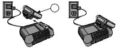
Charging Procedure
1.Plug the charger into an appropriate outlet before inserting the battery pack.
2.Insert the battery pack (6) into the charger, as shown, making sure the pack is fully seated in charger. The red (charging) light will blink continuously, indicating that the charging process has started.
6 |
3.The completion of charge will be indicated by the red light remaining ON continuously. The pack is fully charged and may be used at this time or left in the charger.
9-ENG
Charge Indicators
This charger is designed to detect certain problems that can arise. Problems are indicated by the red light flashing at a fast rate. If this occurs, re-insert the battery pack into the charger. If the problem persists, try a different battery pack to determine if the charger is working properly. If the new pack charges correctly, then the original pack is defective and should be returned to a service center or other collection site for recycling. If the new battery pack elicits the same trouble indication as the original, have the charger and the battery pack tested at an authorized service center.
HOT/COLD DELAY
This charger has a hot/cold delay feature: when the charger detects a battery that is hot, it automatically starts a delay, suspending charging until the battery has cooled. After the battery has cooled, the charger automatically switches to the pack charging mode. This feature ensures maximum battery life. The red light flashes long, then short while in the hot/cold delay mode.
LEAVING THE BATTERY PACK IN THE CHARGER
The charger and battery pack can be left connected with the charge indicator showing Pack Charged.
WEAK BATTERY PACKS: Weak batteries will continue to function but should not be expected to perform as much work.
FAULTY BATTERY PACKS: This charger will not charge a faulty battery pack. The charger will indicate faulty battery pack by refusing to light or by displaying problem pack or charger.
NOTE: This could also mean a problem with a charger.
PROBLEM POWER LINE
Some chargers have a Problem Power Line indicator. When the charger is used with some portable power sources such as generators or sources that convert DC to AC, the charger may temporarily suspend operation, flashing the red light with two fast blinks followed by a pause. This indicates the power source is out of limits.
Important Charging Notes
1.Longest life and best performance can be obtained if the battery pack is charged when the air temperature is between 65 °F and 75 °F (18° – 24 °C). DO NOT charge the battery pack in an air temperature below +40 °F (+4.5 °C), or above +105 °F (+40.5 °C). This is important and will prevent serious damage to the battery pack.
2.The charger and battery pack may become warm to the touch while charging. This is a normal condition, and does not indicate a problem. To facilitate the cooling of the battery pack after use, avoid placing the charger or battery pack in a warm environment such as in a metal shed or an uninsulated trailer.
3.If the battery pack does not charge properly: a) Check operation of receptacle by plugging in a lamp or other appliance; b) Check to see if receptacle is connected to a light switch which turns power off when you turn out the lights; c) Move the charger and battery pack to a location where the surrounding air temperature is approximately 65 °F – 75 °F (18° – 24 °C); d) If charging problems persist, take the tool, battery pack and charger to your local service center.
4.The battery pack should be recharged when it fails to produce sufficient power on jobs which were easily done previously. DO NOT CONTINUE to use under these conditions. Follow the charging procedure. You may also charge a partially used pack whenever you desire with no adverse effect on the battery pack.
5.Foreign materials of a conductive nature such as, but not limited to, grinding dust, metal chips, steel wool, aluminum foil, or any buildup of metallic particles should be kept away from charger cavities. Always unplug the charger from the power supply when there is no battery pack in the cavity. Unplug the charger before attempting to clean.
6.Do not freeze or immerse the charger in water or any other liquid.
10-ENG


 Shock hazard. Don’t allow any liquid to get inside the charger. Electric shock may result.


 Never attempt to open the battery pack for any reason. If the plastic housing of the battery pack breaks or cracks, return to a service center for recycling.
Storage Recommendations
1.The best storage place is one that is cool and dry, away from direct sunlight and excess heat or cold.
2.For long storage, it is recommended to store a fully charged battery pack in a cool dry place out of the charger for optimal results.
 Battery packs should not be stored completely depleted of charge. The battery pack will need to be recharged before use.
SAVE THESE INSTRUCTIONS FOR FUTURE USE SPECIFICATIONS
Tool
|
4 |
5 |
1 |
|
6 |
|
|
|
|
|
7 |
|
2 |
8 |
|
|
|
3 |
10 |
9 |
|
NO. |
COMPONENT |
|
|
1 |
Driver Bolt Cover |
2 |
Clinch Dial |
3 |
Leg Length Dial |
4 |
Tool Hanger |
5 |
Safety Lever |
NO. |
COMPONENT |
|
|
6 |
Battery |
7 |
Trigger |
8 |
Magazine |
9 |
Base |
10 |
Depth Adjustment Knob |
MODEL |
LENGTH |
HEIGHT |
WIDTH |
WEIGHT |
|
|
|
|
|
|
|
DSW-3519 |
13.5" |
8" |
4.5" |
6.2 lb |
|
DSW-3522 |
|||||
(342.9 mm) |
(203.2 mm) |
(114.3) |
(2.81 kg) |
||
DSC-3219 |
|||||
|
|
|
|
11-ENG

Part/Staple Chart
MODEL |
DSW-3519 |
DSW-3522 |
DSC-3219 |
||||
BOSTITCH |
SW74375/8 |
SW74373/4 |
SW74373/4 |
SW90407/8 |
B58C |
B34C |
|
STAPLE |
SW90405/8 |
SW90403/4 |
SW90403/4 |
||||
|
|
|
|||||
LEG |
5/8" |
3/4" |
3/4" |
7/8" |
5/8" |
3/4" |
|
LENGTH |
(16 mm) |
(19 mm) |
(19 mm) |
(22 mm) |
(16 mm) |
(19 mm) |
|
DIAL |
|
|
|
|
|
|
|
POSITION |
|
|
|
|
|
|
|
Corrugate Thickness Chart
MODEL |
DSW-3519 / DSC-3219 |
DSW-3522 |
|||
|
|
|
|
|
|
FASTENER |
5/8" |
3/4" |
3/4" |
7/8" |
|
(15 mm) |
(19 mm) |
(19 mm) |
(22 mm) |
||
|
|||||
MAXIMUM RECOMMENDED |
0.38" |
0.44" |
0.53" |
0.58" |
|
CORRUGATE THICKNESS |
|||||
(9.7 mm) |
(11.1 mm) |
(13.5 mm) |
(14.6 mm) |
||
|
|||||
|
|
|
|
|
|
Fastener Specifications
STAPLE |
TOOL |
WIRE SIZE |
CROWN |
LEG LENGTH |
|
SERIES |
MODEL |
WIDTH |
|||
|
|
||||
SW74375/8 |
DSW-3519 |
.074" x .037" |
1-3/8" |
5/8" |
|
(1.88 x .94 mm) |
(35 mm) |
(15 mm) |
|||
|
|
||||
SW90405/8 |
DSW-3519 |
.090" x .040" |
1-3/8" |
5/8" |
|
(2.29 x 1.02 mm) |
(35 mm) |
(15 mm) |
|||
|
|
||||
SW74373/4 |
DSW-3519 |
.074" x .037" |
1-3/8" |
3/4" |
|
DSW-3522 |
(1.88 x .94 mm) |
(35 mm) |
(19 mm) |
||
|
|||||
SW90403/4 |
DSW-3519 |
.090" x .040" |
1-3/8" |
3/4" |
|
DSW-3522 |
(2.29 x 1.02 mm) |
(35 mm) |
(19 mm) |
||
|
|||||
SW90407/8 |
DSW-3522 |
.090" x .040" |
1-3/8" |
7/8" |
|
(2.29 x 1.02 mm)) |
(35 mm) |
(22 mm) |
|||
|
|
||||
B58C |
DSC-3219 |
.074" x .037" |
1-1/4" |
5/8" |
|
(1.88 x .94 mm) |
(32 mm) |
(15 mm) |
|||
|
|
||||
B34C |
DSC-3219 |
.074" x .037" |
1-1/4" |
3/4" |
|
(1.88 x .94 mm) |
(32 mm) |
(19 mm) |
|||
|
|
12-ENG

ASSEMBLY |
|
Loading The Tool |
POSITION 1 |
|
|
When loading tool: 1) Never place a hand |
|
or any part of body in fastener discharge area of tool; |
|
2) Never point tool at anyone; 3) Do not pull the trigger |
|
or depress the safety lever as accidental actuation may |
|
occur, possibly causing injury. |
|
1. Disconnect the battery. |
|
2. Pull back the pusher until it is tucked under the rear of the |
|
magazine in POSITION 1. |
POSITION 2 |
3.Check staple leg length.
Adjustment is provided in the tool for different staple leg lengths.
A)To adjust the tool for leg length install the correct clinchers and adjust the length dial to the setting
corresponding to the fastener being driven.
4.Load the staple stick from the rear of the tool
(POSITION 2).
5.Slide the pusher from POSITION 1 until engaged behind the staples.
Battery Installation
INSTALLING AND REMOVING THE BATTERY PACK
Make sure your battery pack is fully charged. To install the battery pack
(6) into the tool handle, align the battery with the rails inside the tool’s handle and slide it firmly into the handle until you hear the lock snap into place. To remove the battery pack from the tool, press the release button (11) and firmly pull the battery pack out of the tool handle. Insert it into the charger as described in the charger section of this manual.
11 |
6 |
11 |
6 |
13-ENG
OPERATION
Operating the Tool
1.Install the battery on the tool.
2.Grasp the handle of the tool with one hand ensuring to depress the safety lever.
3.Align the tool on the work piece using the marks on the side of tool to indicate where the fastener is ejected.
4.Depress the trigger to actuate the tool.
5.Once the cycle has completed move the tool to the next location.
SAFETY LEVER RELEASED POSITION |
SAFETY LEVER DEPRESS POSITION |
ALIGNMENT
MARKS
Tool Operation Check


 Remove all fasteners from tool before performing tool operation check.
TRIGGER OPERATED TOOL
A.With finger off the trigger, hold the tool with a firm grip on the handle ensuring that the safety lever is depressed.
B.Place the nose of the tool against the work surface.
C.Pull the trigger to drive.
THE TOOL WILL CYCLE EACH TIME THE TRIGGER IS PULLED! THIS IS A FULL CYCLE TOOL. PULL THE TRIGGER, AND CLINCHERS WILL DISCHARGE AND RETRACT.


 IN ADDITION TO THE OTHER WARNINGS CONTAINED IN THIS MANUAL OBSERVE THE FOLLOWING FOR SAFE OPERATION:
•Use the BOSTITCH tool only for the purpose for which it was designed.
•Never use this tool in a manner that could cause a fastener to be directed toward the user or others in the work area.
•Do not use the tool as a hammer.
•Always carry the tool by the handle.
•Do not alter or modify this tool from the original design or function.
•Always be aware that misuse and improper handling of this tool can cause injury to yourself and others.
•Never leave a tool unattended with the battery attached.
14-ENG
•Do not operate this tool if it does not contain a legible WARNING LABEL.
•Do not operate tool if all covers are not installed.
•Do not operate the tool when not placed on a work surface.
•Do not use this stapler for fastening electrical cables. It is not designed for electric cable installation and may damage the insulation of electric cables thereby causing electric shock or fire hazards.
ADJUSTMENTS
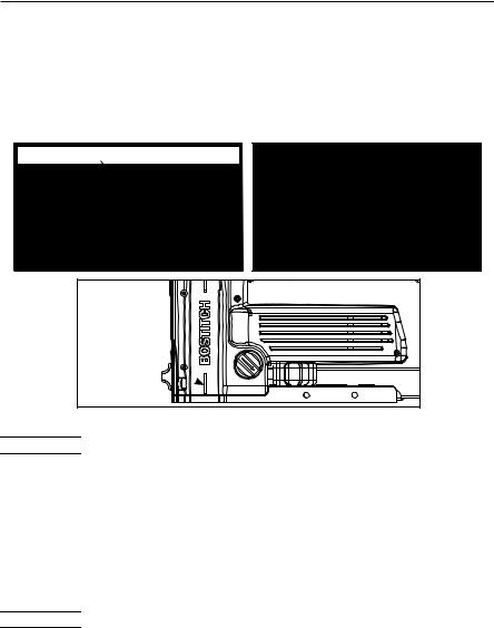
Clinch Adjustment
To obtain maximum efficiency from the staple closure, it is important that the staple be clinched properly. Proper clinching for any thickness board may be obtained by adjusting the clincher setting with staples of proper leg length. Use the proper length staples for the thickness of work to be stapled, otherwise unnecessary pressure is exerted and staple crowns and legs will be distorted, or the clinch will be too loose.
 Disconnect the battery before adjusting the clinch tightness of the tool.
1.To loosen the fastener clinch turn the clinch dial to the right.
2.To tighten the fastener clinch, turn the clinch dial to the left.
|
CLINCH |
TIGHT |
DIAL |
|
|
MEDIUM |
|
LOOSE |
|
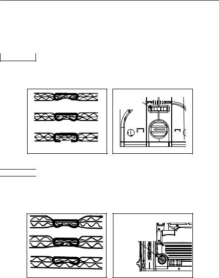
Depth Of Drive Adjustment


 Remove the battery before adjusting the depth of drive.
1.Push to release the locking feature, and turn the depth adjustment knob clockwise to decrease the depth of drive.
2.Push to release the locking feature, and turn the depth adjustment knob counter clockwise to increase the depth of drive.
DEPTH
DEEP ADJUSTMENT
KNOB
MEDIUM
SHALLOW
15-ENG
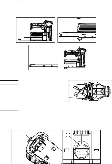
Magazine Removal


 Remove the battery before removing the magazine.
1.Remove all fasteners from the magazine
2.Rotate the magazine release lever down to free the magazine (POSITION 2).
3.Pull the magazine back to remove from the tool (POSITION 3).
POSITION 1 |
POSITION 2 |
POSITION 3 |
Jammed Staple Removal


 Remove the battery from the tool
before removing jammed staples.
1. Remove the magazine from the tool.
2.Carefully remove the jammed fastener from the tool.
3.Reinstall the magazine.
Leg Length Adjustment


 Remove the battery before adjusting the leg length.
1.Loosen the Leg Length Lock Screw on the bottom of the tool.
2.Turn the Leg Length Dial (3) with a flat blade screw driver until the arrow is pointed at the correct setting for the staple being driven.
3.Tighten the Leg Length Lock Screw.
LEG |
LENGTH |
LOCK |
SCREW |
3 |
16-ENG

MAINTAINING AND SERVICING THE POWER TOOL
A)Blow dirt and dust out of all air vents with clean, dry air at least once a week. To minimize the risk of eye injury, always wear ANSI Z87.1 approved eye protection when performing this.
B)Never use solvents or other harsh chemicals for cleaning the non-metallic parts of the tool. These chemicals may weaken the plastic materials used in these parts. Use a cloth dampened only with water and mild soap. Never let any liquid get inside the tool; never immerse any part of the tool into a liquid
CToobtainserviceonyourBOSTITCHpowertoolcontactBOSTITCHcustomerserviceat 1-800-832-3080 for the location of the service center in your area.
TROUBLE SHOOTING
PROBLEM |
CAUSE |
CORRECTION |
|
|
|
|
|
Skipping |
Loose magazine |
Re-engage the magazine |
|
fasteners/ |
|
release lever |
|
intermittent |
|
|
|
Fasteners out of spec. |
Replace with recommended |
||
feed |
|||
|
fasteners |
||
|
|
||
|
|
|
|
|
Dirt/debris in the magazine |
Clean and dry the magazine |
|
|
|
|
|
|
Dirt/debris in the drive channel |
Clean the drive channel |
|
|
|
|
|
Fasteners jam in |
Wrong size fasteners |
Replace with recommended |
|
the tool |
|
fasteners |
|
|
|
|
|
|
Bent fasteners |
Discontinue using these |
|
|
|
fasteners |
|
|
|
|
|
|
Broken/chipped driver |
Replace driver |
|
|
|
|
|
|
Worn pusher |
Replace pusher |
|
|
|
|
|
|
Loose magazine |
Re-engage the magazine |
|
|
|
release lever |
|
|
|
|
|
|
Fasteners out of spec. |
Replace with recommended |
|
|
|
fasteners |
|
|
|
|
|
|
Dirt/debris in the magazine |
Clean and dry the magazine |
|
|
|
|
|
|
Dirt /debris in the drive |
Clean the drive channel |
|
|
channel |
|
|
|
|
|
|
|
Worn/damaged pusher spring |
Replace pusher spring |
|
|
|
|
|
Slow drive |
Discharged Battery |
Recharge battery |
|
speed or stalling |
|
|
|
Depleted Battery |
Replace battery |
||
|
|
|
|
|
Cardboard too thick |
Reduce cardboard thickness |
|
|
|
|
|
Poor clinch |
Wrong leg length setting |
Set leg length according to |
|
|
|
clinchers and fasteners |
|
|
|
|
|
|
Worn driver guide |
Replace the driver guide |
|
|
|
|
|
|
Broken/bent clinchers |
Replace clinchers |
|
|
|
|
17-ENG
 Loading...