


FN1664
OIL-FREE FINISH NAILER
CLAVADORA SINACEITEPARATERMINACIONES CLOUEUR DE FINITION SANS HUILEDE QUALITÉ
OPERATION and MAINTENANCE MANUAL MANUAL DE OPERACIÓN Y DE MANTENIMIENTO MANUEL D’INSTRUCTIONS ET D’ENTRETIEN
BEFORE OPERATING THIS TOOL, ALL OPERATORS SHOULD STUDY THIS MANUAL TO UNDERSTAND AND FOLLOW THE SAFETY WARNINGS AND INSTRUCTIONS. KEEP THESE INSTRUCTIONS WITH THE TOOL FOR FUTURE REFERENCE. IF YOU HAVE ANY QUESTIONS, CONTACTYOUR BOSTITCH REPRESENTATIVEOR DISTRIBUTOR.
ANTES DE OPERAR ESTA HERRAMIENTA, TODOS LOS OPERADORES DEBERÁN ESTUDIAR ESTE MANUALPARAPODERCOMPRENDER Y SEGUIR LAS ADVERTENCIASSOBRESEGURIDAD Y LAS INSTRUCCIONES. MANTENGA ESTAS INSTRUCCIONES CON LA HERRAMIENTAPARA FUTURA REFERENCIA, SI TIENE ALGUNADUDA, COMUNÍQUESE CON SU REPRESENTANTEDE BOSTITCH O CON SU DISTRIBUIDOR.
LIRE ATTENTIVEMENT LE PRÉSENT MANUEL AVANT D’UTILISER L’APPAREIL. PRÉTER UNE ATTENTION TOUTE PARTICULIÈRE AUX CONSIGNESDE SÉCURITÉ ET AUX AVERTISSEMENTS. GARDER CE MANUELAVECL’OUTILPOUR FUTURRÉFÉRENCE. SI VOUSAVEZ DES QUESTIONS, CONTACTEZ VOTRE REPRÉSENTANT OU VOTRECONCESSIONNAIRE BOSTITCH.
|
|
|
|
180586REVB 09/08 |
STANLEY FASTENING SYSTEMS L.P. |
||
|
|
|
|

INTRODUCTION
The Bostitch FN1664 a precision-built tool, designed for high speed, high volume fastening. This tool will deliver efficient, dependable service when used correctly and with care. As with any fine power tool, for best performance the manufacturer’s instructions must be followed. Please study this manual before operating the tool and understand the safety warnings and cautions. The instructions on installation, operation and maintenance should be read carefully, and the manuals kept for reference. NOTE: Additional safety measures may be required because of your particular application of the tool. Contact your Bostitch representative or distributor with any questions concerning the tool and its use. Bostitch, Inc., East Greenwich, Rhode Island 02818.
INDEX
Safety Instructions . . . . . . . . . . . . . . . . . . . . . . . . . . . . . . . . . . . . . . . . . |
. . . . 3 |
Tool Components . . . . . . . . . . . . . . . . . . . . . . . . . . . . . . . . . . . . . . . . . . . . |
. . . 4 |
Tool Specifications . . . . . . . . . . . . . . . . . . . . . . . . . . . . . . . . . . . . . . . . . . |
. . . 5 |
Air Supply & Connections . . . . . . . . . . . . . . . . . . . . . . . . . . . . . . . . . . . . . |
. . . 6 |
Loading the Tool . . . . . . . . . . . . . . . . . . . . . . . . . . . . . . . . . . . . . . . . . . . . |
. . . 7 |
Trigger Lockout & Selecting Trip Mode . . . . . . . . . . . . . . . . . . . . . . . . . . . |
. . . 8 |
Dial-A-Depth™ . . . . . . . . . . . . . . . . . . . . . . . . . . . . . . . . . . . . . . . . . . . . . . |
. . . 9 |
Installing the Belt Hook . . . . . . . . . . . . . . . . . . . . . . . . . . . . . . . . . . . . . . . |
. . 10 |
Tool Operation . . . . . . . . . . . . . . . . . . . . . . . . . . . . . . . . . . . . . . . . . . . . . . |
. . 11 |
Jam Clearing Procedure . . . . . . . . . . . . . . . . . . . . . . . . . . . . . . . . . . . . . |
. . 12 |
Maintaining the Pneumatic Tool . . . . . . . . . . . . . . . . . . . . . . . . . . . . . . . |
13-14 |
Trouble Shooting . . . . . . . . . . . . . . . . . . . . . . . . . . . . . . . . . . . . . . . . . . . |
. . 15 |
Available Accessories . . . . . . . . . . . . . . . . . . . . . . . . . . . . . . . . . . . . . . . . |
. . 16 |
Bostitch Finish & Trim Products. . . . . . . . . . . . . . . . . . . . . . . . . . . . . . . . . |
. . 17 |
NOTE:
Bostitch tools have been engineered to provide excellent customer satisfaction and are designed to achieve maximum performance when used with precision Bostitch fasteners engineered to the same exacting standards. Bostitch cannot assume responsibility for product performance if our tools are used with fasteners or accessories not meeting the specific requirements established for genuine Bostitch nails, staples and accessories.
 ™
™
LIMITED WARRANTY — U.S. and Canada Only
Effective December 1, 2005 Bostitch, L.P.warrants to the originalretail purchaser that the productpurchasedis free from defects in materialand workmanship,and agrees to repairor replace, at Bostitch’soption, any defective Bostitch brandedpneumatic stapleror nailer for a periodof seven(7) years from date of purchase(one (1) year from the date of purchasefor compressorsandtools usedin productionapplications). Warrantyis nottransferable.Proofof purchase date required. This warrantycoversonly damageresultingfrom defects in materialor workmanship;it does not cover conditionsor malfunctions resulting from normal wear,neglect,abuse,accident or repairsattemptedor madeby other than our nationalrepair center or authorizedwarranty service centers. Driver blades,bumpers,o-rings, pistonsand piston ringsare considerednormally wearingparts. For optimalperformance of your Bostitchtool alwaysuse genuine Bostitch fastenersand replacementparts.
THIS WARRANTY IS IN LIEU OF ALL OTHER WARRANTIES, EXPRESS OR IMPLIED,INCLUDINGBUT NOT LIMITED TO THE IMPLIED WARRANTIES OF MERCHANTABILITY OR FITNESS FOR A PARTICULAR PURPOSE. BOSTITCH SHALLNOT BE LIABLE FOR ANY INCIDENTAL OR CONSEQUENTIAL DAMAGES.
Some statesand countriesdo not allow limitationson how longan implied warrantylasts, or the exclusion or limitation of incidentalor consequential damages, so the above limitationsor exclusions may not apply to you. This warranty gives you specific legalrights,andyou mayalsohaveotherrightswhich vary from stateto stateandcountryto country.
Toobtain warranty servicein the U.S. returnthe product,togetherwithproof of purchase,to the U.S. BostitchNational or Regional IndependentAuthorized Warranty Service Center.In the U.S. you may call us at 1-800-556-6696or visit www.BOSTITCH.com for the location most convenientfor you. In Canada please call us at 800-567-7705or visit www.BOSTITCH.com
-2-
SAFETY INSTRUCTIONS
EYE PROTECTION which conforms to ANSI specifications and provides protection against flying particles both from the FRONT and SIDE should ALWAYS be worn by the operator and others in the work area when connecting to air supply, loading, operating or servicing this tool. Eye protection is required to guard against flying fasteners and debris, which could cause severe eye injury.
The employer and/or user must ensure that proper eye protection is worn. Eye protection equipment must conform to the requirements of the American National Standards Institute, ANSI Z87.1 and provide both frontal and side protection. NOTE: Non-side shielded spectacles and face shields alone do not provide adequate protection.
CAUTION: Additional Safety Protection will be required in some environments. For example, the working area may include exposure to noise level which can lead to hearing damage. The employer and user must ensure that any necessary hearing protection is provided and used by the operator and others in the work area. Some environments will require the use of head protection equipment. When required, the employer and user must ensure that head protection conforming to ANSI Z89.1 is used.
AIR SUPPLY AND CONNECTIONS
Do not use oxygen, combustible gases, or bottled gases as a power source for this tool as tool may explode, possibly causing injury.
Do not use supply sources which can potentially exceed 200 P.S.I.G. as tool may burst, possibly causing injury.
The connector on the tool must not hold pressure when air supply is disconnected. If a wrong fitting is used, the tool can remain charged with air after disconnecting and thus will be able to drive a fastener even after the air line is disconnected possibly causing injury.
Do not pull trigger or depress contact arm while connected to the air supply as the tool may cycle, possibly causing injury.
Always disconnect air supply: 1.) Before making adjustments; 2.) When servicing the tool; 3.)When clearing a jam; 4.)When tool is not in use; 5.)When moving to a different work area, as accidental actuation may occur, possibly causing injury.
LOADINGTOOL
When loading tool: 1.) Never place a hand or any part of body in fastener discharge area of tool; 2.) Never point tool at anyone; 3.) Do not pull the trigger or depress the trip as accidental actuation may occur, possibly causing injury.
OPERATION
Always handle the tool with care: 1.) Never engage in horseplay; 2.) Never pull the trigger unless nose is directed toward the work; 3.) Keep others a safe distance from the tool while tool is in operation as accidental actuation may occur,possibly causing injury.
The operator must not hold the trigger pulled on contact arm tools except during fastening operation as serious injury could result if the trip accidentally contacted someone or something, causing the tool to cycle.
Keep hands and body away from the discharge area of the tool. A contact arm tool may bounce from the recoil of driving a fastener and an unwanted second fastener may be driven possibly causing injury.
Check operation of the contact arm mechanism frequently. Do not use the tool if the arm is not working correctly as accidental driving of a fastener may result. Do not interfere with the proper operation of the contact arm mechanism.
Do not drive fasteners on top of other fasteners or with the tool at an overly steep angle as this may cause deflection of fasteners which could cause injury.
Do not drive fasteners close to the edge of the work piece as the wood may split, allowing the fastener to be deflected possibly causing injury.
This nailerproducesSPARKSduringoperation. NEVERuse the nailernearflammablesubstances, gases or vapors including lacquer, paint, benzine, thinner,gasoline, adhesives, mastics, glues or any other material that is -- or the vapors, fumes or by-products of which are -- flammable, combustible or explosive. Using the nailer in any such environment could cause an EXPLOSION resulting in personal injury or death to user and bystanders.
MAINTAININGTHETOOL
When working on air tools note the warnings in this manual and use extra care when evaluating problem tools.
-3-
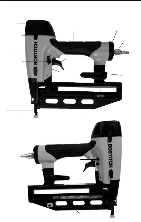
TOOL COMPONENTS
Frame Cap
Frame Protector
Frame
Trigger Lockout
Actuation Mode
Selector Switch
Trip
No-Mar Tip
Over-Molded
Comfort Grip
Trigger
Dial-A-Depth™
Control
Belt Hook
Trigger Lockout
Rear Exhaust
Swivel Air Fitting
Pencil Sharpener
3mm Hex Wrench
Spare No Mar Tip Storage |
|
4mm Hex Wrench |
|
-4-

TOOL SPECIFICATIONS
All demensions in inches unless otherwise specified.
|
FN1664 |
Description |
16ga Finish Nailer |
Engine Type |
Oil-Free |
Operation Pressure Range |
70-120 PSI (4.9 to 8.43kg/cm2) |
Maximum Operation Pressure |
120 PSI (8.43 kg/cm2) |
Fastener Type |
SB16 Series |
Fastener Gauge |
16 Gauge |
Fastener Range |
1” – 2-1/2” (25mm–63mm) |
Magazine Capacity |
110 |
Length |
11-7/8” (301.6mm) |
Width |
3-3/8” (85.7mm) |
Height |
11-3/8” (288.9mm) |
Weight |
3.9 lbs. (1.7kg) |
|
|
Operating Pressure:
70 to 120 p.s.i.g. (4.9 to 8.43 kg/cm2). Select the operating pressure within in this range for best fastener performance.
DO NOT EXCEED THIS RECOMMENDED OPERATING PRESSURE.
Air Consumption:
The FN1664 requires 3.9 cubic feet per minute or C.F.M. (110.4 liters per minute or LT/MIN) of free air at 80PSI (5.6 kg/cm2) to operate at a rate of 60 fasteners per minute. To determine the appropriately sized air compressor, take the actual rate at which the tool will be run and compare the required C.F.M. (LT/MIN) to the compressors free air delivery (C.F.M./ LT/MIN) at 80 PSI (5.6 kg/cm2).
For example, if your fastener usage averages 30 fasteners per minute, you need 50% of the tools C.F.M. required to operate the tool at the rate of 60 fasteners per minute. In this case, be sure that your air compressor can deliver a minimum of 1.90 C.F.M. (55.2 LT/MIN) at 80 PSI(5.6 kg/cm2) for optimum performance.
FASTENER SPECIFICATIONS
Tool Model |
Fastener Type |
Fastener SKU |
Gauge |
Length |
FN1664 |
|
SB16-1.25 |
16 |
1-1/4” (32mm) |
FN1664 |
|
SB16-1.50 |
16 |
1-1/2” (38mm) |
FN1664FN1664 |
|
SB16-1.75 |
16 |
1-3/4” (45mm) |
FN1664 |
|
SB16-2.00 |
16 |
2” (50mm) |
|
Straight Finish Nails |
SB16-2.50 |
16 |
2-1/2” (63mm) |
|
|
|
|
|
* Stainless steel fasteners also available in certain sizes. Visit www.BOSTITCH.com for further details.
NOTE:
BOSTITCH tools have been engineered to provide superior customer satisfaction and are designed to achieve maximum perfomance when used with precision BOSTITICH fasteners engineered to the same exacting standards. BOSTITCH cannot assume responsibility for product performance if our tools are used with fasteners or accessories not meeting the specific requirements established for genuine BOSTITCH fasteners and accessories.
-5-

AIR SUPPLY AND CONNECTIONS
Do not use oxygen, combustible gases, or bottled gases as a power source for this tool as tool may explode, possibly causing injury.
FITTINGS:
Install a male plug on the tool which is free flowing and which will release air pressure from the tool when disconnected from the supply source.
HOSES:
Air hoses should have a minimum of 150 p.s.i. (10.6 kg/cm2) working pressure rating or 150 percent of the maximum pressure that could be produced in the air system. The supply hose should contain a fitting that will provide “quick disconnecting” from the male plug on the tool.
SUPPLY SOURCE:
Use only clean regulated compressed air as a power sourcefor this tool. NEVER USE OXYGEN, COMBUSTIBLE GASES, OR BOTTLED GASES,AS A POWER SOURCE FOR THIS TOOL AS TOOL MAYEXPLODE.
REGULATOR:
A pressure regulator with an operating pressure of 0 - 125 p.s.i. (0 - 8.79 kg/cm2) is required to control the operating pressure for safe operation of this tool. Do not connect this tool to air pressure which can potentially exceed 200 p.s.i. (14 kg/cm2) as tool may fracture or burst, possibly causing injury.
OPERATING PRESSURE:
Do not exceed recommended maximum operating pressure as tool wear will be greatly increased. The air supply must be capable of maintaining the operating pressure at the tool. Pressure drops in the air supply can reduce the tool’s driving power. Refer to “TOOL SPECIFICATIONS” for setting the correct operating pressure for the tool.
FILTER:
Dirt and water in the air supply are major causes of wear in pneumatic tools. A filter will help to get the best performance and minimum wear from the tool. The filter must have adequate flow capacity for the specific installation. The filter has to be kept clean to be effective in providing clean compressed air to the tool. Consult the manufacturer’s instructions on proper maintenance of your filter. A dirty and clogged filter will cause a pressure drop which will reduce the tool’s performance.
Quick Connect Plug
Quick Disconnect Plug
-6-
LOADINGTHE FN1664
EYE PROTECTION which conforms to ANSI specifications and provides protection against flying particles both from the FRONT and SIDE should ALWAYSbe worn by the operator and others in the work area when connecting to air supply, loading, operating or servicing this tool. Eye protection is required to guard against flying fasteners and debris, which could cause severe eye injury.
The employer and/or user must ensure that proper eye protection is worn. Eye protection equipment must conform to the requirements of the American National Standards Institute, ANSI Z87.1 and provide both frontal and side protection. NOTE: Non-side shielded spectacles and face shields alone do not provide adequate protection.
TO PREVENT ACCIDENTAL INJURIES:
•Never place a hand or any other part of the body in nail discharge area of tool while the air supply is connected.
•Never point the tool at anyone else.
•Never engage in horseplay.
•Never pull the trigger unless nose is directed at the work.
•Always handle the tool with care.
•Do not pull the trigger or depress the trip mechanism while loading the tool.
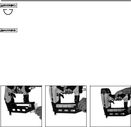
LOADING THE FN1664
1.Load nails through the slot in the rear of the magazine and past retaining clip.
2.Pull pusher back behind nail stick and release.
3.Ensure magazine pusher is behind the last nail stick.
-7-

TRIGGER LOCKOUT CONTROL
The trigger lockout control feature on BOSTITCH pneumatic tools provides a trigger lock feature for added safety control. Push the lockout control button in or out to activate or lock the tool trigger.
Trigger Lockout Control Button
TRIP OPERATION MODE
Warning: Always disconnect air supply before making adjustments as accidental actuation may occur, possibly causing injury.
The FN1664 features a selectable trigger system that allows the user to choose between the following modes of operation:
1. Contact TripOperation |
2. Sequential Trip Operation |
1. CONTACTTRIP:
The common operation procedure on “Contact Trip” tools is for the operator to contact the work surface to actuate the trip mechanism while keeping the trigger pulled, thus driving a fastener each time the work surface is contacted. This will allow rapid fastener placement on many jobs. All pneumatic tools are subject to recoil when driving fasteners. The tool may bounce, releasing the trip, and if unintentionally allowed to recontact the work surface with the trigger still actuated (finger still holding the trigger pulled) an unwanted second fastener will be driven.
2. SEQUENTIAL TRIP:
The Sequential Trip requires the operator to hold the tool against the work before pulling the trigger. This makes accurate fastener placement easier. The Sequential Trip allows exact fastener location without the possibility if driving a second fastener on recoil as described under “Contact Trip”. The Sequential Trip Tool has a positive advantage because it will not accidentally drive a fastener if the tool is contacted against the work surface - or anything else - while the operator is holding the trigger pulled.
SELECTING THE TRIP MODE:
To ensure safety, the user must lock the trigger (as described above) before changing the trigger system. To change the trip mode, rotate the mode switch in the counterclockwise direction. The mode switch will lock automatically when the indicating arrow is pointing down to the 3 nail icon stamped into the tool frame (Contact Trip Mode) or to a single nail icon stamped in the tool frame( Sequential Trip Mode). Unlock the trigger to resume tool operation.
Contact Trip Mode |
Sequential Trip Mode |
(trip mode selector switch pointing down) |
(trip mode selector switch pointing up) |
-8-

DIAL-A-DEPTH™ FASTENER CONTROL ADJUSTMENT
The DIAL-A-DEPTH™ Fastener control adjustment feature provides close control of the fastener drive depth: from flush with the work surface to shallow or deep countersink.
First set the air pressure for consistent drive in the specific work as described on page 4, then use the DIAL-A-DEPTH™ fastener control adjustment to give the desired depth of drive.
Dial-A-DepthTM Fastener Control Adjustment
IN ADDITIONTOTHE OTHER WARNINGS CONTAINED INTHIS MANUAL OBSERVETHE FOLLOWING FOR SAFE OPERATION
•Use the BOSTITCH pneumatic tool only for the purpose for which it was designed.
•Never use this tool in a manner that could cause a fastener to be directed toward the user or others in the work area.
•Do not use the tool as a hammer.
•Always carry the tool by the handle. Never carry the tool by the air hose.
•Do not alter or modify this tool from the original design or function without approval from BOSTITCH, INC.
•Always be aware that misuse and improper handling of this tool can cause injury to yourself and others.
•Never clamp or tape the trigger or contact trip in an actuated position.
•Never leave a tool unattended with the air hose attached.
• Do not operate this tool if it does not contain a legible WARNING LABEL.
•Do not continue to use a tool that leaks air or does not function properly.Notify your nearest Bostitch representative if your tool continues to experience functional problems.
-9-

INSTALLING THE BELT HOOK
Always disconnect tool from air supply before making adjustments or before attempting any part assembly or disassembly.
Always remove the belt hook from the tool when selecting Contact TripMode.
1.Assure that the sequential trip mode is selected.
2.Depress the belt hook release button on the belt hook body.
3.Slide the belt hook into the belt hook attachment slot.
4.Release the belt hook release button and check to ensure that the belt hook is locked in position.
1 |
|
|
2 |
|
|
3 |
|
|
4 |
|
|
|
|
|
|
|
|
|
|
|
|
|
|
|
|
|
|
|
|
|
|
|
USINGTHE INTEGRATED PENCIL SHARPENER
A standard pencil sharpener is integrated into the belt hook for the operator’s convenience. To sharpen a pencil, insert any standard pencil into the hole and rotate the pencil to the right (clockwise)to sharpen.
HEX WRENCH STORAGE
A 3mm hex wrench for servicing the tool is stored within the belt hook. To remove the hex wrench, push out the short end of the hex wrench from the backside of the belt hook. Then grasp the hex wrench from the front of the belt hook and remove.
-10-
TOOL OPERATION
EYE PROTECTION which conforms to ANSI specifications and provides protection against flying particles both from the FRONT and SIDE should ALWAYS be worn by the operator and others in the work area when connecting to air supply, loading, operating or servicing this tool. Eye protection is required to guard against flying fasteners and debris, which could cause severe eye injury.
The employer and/or user must ensure that proper eye protection is worn. Eye protection equipment must conform to the requirements of the American National Standards Institute, ANSI Z87.1and provide both frontal and side protection. NOTE: Non-side shielded spectacles and face shields alone do not provide adequate protection.
BEFORE HANDLING OR OPERATING THIS TOOL:
I.READ AND UNDERSTAND THE WARNINGS CONTAINED IN THIS MANUAL.
II.REFER TO “TOOL SPECIFICATIONS” IN THIS MANUALTO IDENTIFY THE OPERATING SYSTEM ON YOURTOOL.
OPERATION
1. CONTACT TRIP OPERATION:
In CONTACT TRIP MODE the tool contains a contact trip that operates in conjunction with the trigger to drive a fastener. There are two methods of operation to drive fasteners with a contact trip tool.
A.SINGLE FASTENER PLACEMENT: To operate the tool in this manner, first position the contact trip on the work surface, WITHOUT PULLING THE TRIGGER. Depress the contact trip until the nose touches the work surface and then pull the trigger to drive a fastener. Do not press the tool against the work with extra force. Instead, allow the tool to recoil off the work surface to avoid a second unwanted fastener. Remove your finger from the trigger after each operation.
B.RAPID FASTENER OPERATION: To operate the tool in this manner, hold the tool with the contact trip pointing towards but not touching the work surface. Pull the trigger and then tap the contact trip against the work surface using a bouncing motion. Each depression of the contact trip will cause a fastener to be driven.
The operator must not hold the trigger pulled on contact trip tools except during fastening operation, as serious injury could result if the trip accidentally contacted someone or something, causing the tool to cycle.
Keep hands and body away from the discharge area of the tool. A contact trip tool may bounce from the recoil of driving a fastener and an unwanted second fastener may be driven, possibly causing injury.
2. SEQUENTIALTRIP OPERATION:
In SEQUENTIAL TRIP MODE the contact trip operates in conjunction with the trigger to drive a fastener. Tooperate a sequential trip tool, first position the contact trip on the work surface WITHOUT PULLING THE TRIGGER. Depress the contact trip and then pull the trigger to drive a fastener. As long as the contact trip is contacting the work and is held depressed, the tool will drive a fastener each time the trigger is depressed. If the contact trip is allowed to leave the work surface, the sequence described above must be repeated to drive another fastener.
-11-

JAM CLEARING PROCEDURE
Disconnect tool from air supply before making adjustments or before attempting any part assembly or disassembly.
On occasion nails can jam in the nose of a pneumatic nailer. This can be caused by striking a metal plate in the wall, drywall screw, or some other hard object. The FN1664 feature open drive channel architecture for jam clearing. To clear a jam follow this procedure:
1.Disconnect the tool from the air supply.
2.Release the pusher so it is no longer applying force to the nail sticks.
3.Open the jam clearing nose door by pulling down and then up on the latch.
4.Remove the jammed fastener. In certain circumstances, pliers may be required to remove the fastener.
5.Close the jam clearing nose door latch.
6.Pull nail pusher back behind nail sticks.
.
FN1664 JAM CLEARING
1 |
2 |
3 |
|
4 |
5 |
6 |
|
-12-

TOOL OPERATION CHECK
CAUTION: Remove all fasteners from tool before performing tool operation check.
1.CONTACT TRIP OPERATION:
A.With finger off the trigger, press the contact trip against the work surface.
THE TOOL MUST NOT CYCLE.
B.Hold the tool off the work surface, and pull the trigger.
THE TOOL MUST NOT CYCLE.
C.With the tool off the work surface, pull the trigger. Press the contact trip against the work surface.
THE TOOL MUST CYCLE.
D.Without touching the trigger, press the contact trip against the work surface, then pull the trigger.
THE TOOL MUST CYCLE.
2.SEQUENTIAL TRIP OPERATION:
A.Press the contact trip against the work surface, without touching the trigger.
THE TOOL MUST NOT CYCLE.
B.Hold the tool off the work surface and pull the trigger.
THE TOOL MUST NOT CYCLE.
Release the trigger. The trigger must return to the trigger stop on the frame.
C.Pull the trigger and press the contact trip against the work surface.
THE TOOL MUST NOT CYCLE.
D.With finger off the trigger, press the contact trip against the work surface. Pull the trigger.
THE TOOL MUST CYCLE.
MAINTAININGTHE PNEUMATICTOOL
When working on air tools, note the warnings in this manual and use extra care evaluating problem tools.
CAUTION: Pusher spring (constant force spring). Caution must be used when working with the spring assembly. The spring is wrapped around, but not attached to, a roller. If the spring is extended beyond its length, the end will come off the roller and the spring will roll up with a snap, with a chance of pinching your hand. Also the edges of the spring are very thin and could cut. Care must also be taken to insure no permanent kinks are put in the spring as this will reduce the springs force.
REPLACEMENT PARTS:
Use only genuine BOSTITCH replacement parts. Do not use modified parts.
ASSEMBLY PROCEDURE FOR SEALS:
When repairing a tool, make sure the internal parts are clean and lubricated. Use Parker “O”-LUBE, Magnalube, or equivalent on all “O”-rings. Coat each “O”-ring with lubricant before assembling.
AIR SUPPLY-PRESSURE AND VOLUME:
Air volume is as important as air pressure. The air volume supplied to the tool may be inadequate because of undersize fittings and hoses, or from the effects of dirt and water in the system. Restricted air flow will prevent the tool from receiving an adequate volume of air, even though the pressure reading is high. The results will be slow operation, misfeeds or reduced driving power. Before evaluating tool problems for these symptoms, trace the air supply from the tool to the supply source for restrictive connectors, low points containing water and anything else that would prevent full volume flow of air to the tool.
-13-

MAINTENANCE CHECKLIST
Maintenance |
Benefit |
Procedure |
Service Interval |
|
|
|
|
Inspect trigger performance |
Ensure trigger system is in |
Refer to Tool Operation |
Daily |
|
proper working order |
Check section in this manual |
|
|
|
|
|
Drain condensation from air |
Prevents accumlation of |
Open drain cock on tanks |
Daily |
compressor tanks and air |
moisture that can impede tool |
and air filters and drain all |
|
filters (if present) |
performace |
condensate |
|
|
|
|
|
Clean magazine assembly |
Prevents accumlation of |
Blow clean with compressed |
Daily |
|
debris that could cause a jam |
air |
|
|
|
|
|
Clean nose assembly |
Prevents accumlation of |
Blow clean with compressed |
Daily |
|
debris that could cause a jam |
air |
|
|
|
|
|
Ensure all fasteners remain |
Prevent loose parts |
Tighten all fasteners with |
Weekly |
tight |
|
appropriately sized hex |
|
|
|
wrench |
|
|
|
|
|
Check/clean air inlet air filter |
Maintains proper air flow to |
Remove end cap and use |
25,000 Fasteners, or monthly |
|
engine for peak performance. |
compressed air blow gun to |
- if used in dusty location |
|
|
blow filter clean. Replace |
|
|
|
filter as required. |
|
|
|
|
|
Replace no-mar tip |
Prevents marks in softwood |
Removeworn no-martip and |
25,000 Fasteners |
|
applications |
replace with a new tip (a spare tip |
|
|
|
is located on the magazine) |
|
|
|
|
|
Replace swivel air fitting |
Maintains proper air flow to |
Remove worn swivel air fitting |
50,000 Fasteners |
|
engine for peak performance |
and replace with new swivel |
|
|
|
fitting |
|
|
|
|
|
Replace piston/driver |
Maintains consistent drive |
Refer to replacement part kit |
150,000 Fasteners |
assembly |
quality |
instructions |
|
|
|
|
|
Replace O-rings |
Maintains engine for peak |
Refer to replacement part kit |
250,000 Fasteners |
|
performance |
instructions |
|
|
|
|
|
Replace bumper |
Maintains engine for peak |
Refer to replacement part kit |
250,000 Fasteners |
|
performance |
instructions |
|
|
|
|
|
Replace headvalve |
Maintains engine for peak |
Refer to replacement part kit |
250,000 Fasteners |
|
performance |
instructions |
|
|
|
|
|
Replace engine cylinder |
Maintains engine for peak |
Refer to replacement part kit |
500,000 Fasteners |
|
performance |
instructions |
|
|
|
|
|
-14-

TROUBLE SHOOTING
PROBLEM
Trigger valve housing leaks air
Trigger valve stem leaks air
Frame/nose leaks air
Frame/cap leaks air
Failure to cycle
Lack of power; slow to cycle
Skipping fasteners; intermittent feed
Fasteners jam in tool
CAUSE |
CORRECTION |
O-ring cut or cracked . . . . . . . . . . . . . . . . . . . .Replace O-ring
O-ring/seals cut or cracked . . . . . . . . . . . . . .Replace trigger valve assembly
O-ring or gasket is cut or cracked . . . . . . . . .Replace O-ring or gasket
Bumper cracked/worn . . . . . . . . . . . . . . . . . . .Replace bumper
Damaged gasket or seal . . . . . . . . . . . . . . . . .Replace gasket or seal
Cracked/worn head valve . . . . . . . . . . . . . . .Replace head valve
Loose cap screws . . . . . . . . . . . . . . . . . . . . . . .Tighten and recheck
Air supply restriction . . . . . . . . . . . . . . . . . . . .Check air supply equipment Worn head valve . . . . . . . . . . . . . . . . . . . . . . .Replace head valve
Broken cylinder cap spring . . . . . . . . . . . . . . .Replace cylinder cap spring Head valve stuck in cap . . . . . . . . . . . . . . . . . .Disassemble / Check / Lubricate
Broken cylinder cap spring . . . . . . . . . . . . . . |
.Replace cap spring |
Rings/seals cut or cracked . . . . . . . . . . . . . . . |
Replace rings/seals |
Exhaust blocked . . . . . . . . . . . . . . . . . . . . . . . . |
Check bumper, head valve spring |
Trigger assembly worn/leaks . . . . . . . . . . . . . |
Replace trigger assembly |
Dirt/tar build up on driver . . . . . . . . . . . . . . . . |
Disassemble nose/driver to clean |
Cylinder sleeve not seated correctly |
|
on bottom bumper . . . . . . . . . . . . . . . . . . . . . . . |
Disassemble to correct |
Air pressure too low . . . . . . . . . . . . . . . . . . . . . |
Check air supply equipment |
Clogged air filter . . . . . . . . . . . . . . . . . . . . . . . . |
Clean or replace air filter |
Worn bumper . . . . . . . . . . . . . . . . . . . . . . . . . . . |
Replace bumper |
Tar/dirt in driver channel . . . . . . . . . . . . . . . . . |
Disassemble and clean nose and driver |
Air restriction/inadequate air flow through |
|
quick disconnect socket and plug . . . . . . . . . |
Replace quick disconnect fittings |
Worn piston ring . . . . . . . . . . . . . . . . . . . . . . . . |
Replace ring, check driver |
Damaged pusher spring . . . . . . . . . . . . . . . . . . |
Replace spring |
Low air pressure . . . . . . . . . . . . . . . . . . . . . . . . |
Check air supply system to tool |
Loose magazine nose screws . . . . . . . . . . . . |
Tighten all screws |
Fasteners too short for tool . . . . . . . . . . . . . . . |
Use only recommended fasteners |
Bent fasteners . . . . . . . . . . . . . . . . . . . . . . . . . . |
Discontinue using these fasteners |
Wrong size fasteners . . . . . . . . . . . . . . . . . . . . |
Use only recommended fasteners |
Leaking head cap gasket . . . . . . . . . . . . . . . . . |
Tighten screws/replace gasket |
Trigger valve O-ring cut/worn . . . . . . . . . . . . . |
Replace O-ring |
Broken/chipped driver . . . . . . . . . . . . . . . . . . . |
Replace driver (check piston ring) |
Dry/dirty magazine . . . . . . . . . . . . . . . . . . . . . . |
Clean/lubricate use BOSTITCH Air Tool Lubricant |
Worn magazine . . . . . . . . . . . . . . . . . . . . . . . . . |
Replace magazine |
Clogged air filter . . . . . . . . . . . . . . . . . . . . . . . . |
Clean or replace air filter |
Driver channel worn . . . . . . . . . . . . . . . . . . . . .Replace nose/check door
Wrong size fasteners . . . . . . . . . . . . . . . . . . . .Use only recommended fasteners Bent fasteners . . . . . . . . . . . . . . . . . . . . . . . . . .Discontinue using these fasteners Loose magazine/nose screws . . . . . . . . . . . .Tighten all screws Broken/chipped driver . . . . . . . . . . . . . . . . . . .Replace driver
-15-
 Loading...