


BRN175
COIL ROOFING NAILER
CLAVADORA PARA TECHOS CON BOBINA
CLOUEUSE DE TOITURE À ROULEAU
OPERATION and MAINTENANCE MANUAL MANUAL DE OPERACIÓN Y DE MANTENIMIENTO MANUEL D’INSTRUCTIONS ET D’ENTRETIEN
BEFORE OPERATING THIS TOOL, ALL OPERATORS SHOULD STUDY THIS MANUAL TO UNDERSTAND AND FOLLOW THE SAFETY WARNINGS AND INSTRUCTIONS. KEEP THESE INSTRUCTIONS WITH THE TOOL FOR FUTURE REFERENCE. IF YOU HAVE ANY QUESTIONS, CONTACT YOUR BOSTITCH REPRESENTATIVE OR DISTRIBUTOR.
ANTES DE OPERAR ESTA HERRAMIENTA, TODOS LOS OPERADORES DEBERÁN ESTUDIAR ESTE MANUAL PARA PODER COMPRENDER Y SEGUIR LAS ADVERTENCIAS SOBRE SEGURIDAD Y LAS INSTRUCCIONES. MANTENGA ESTAS INSTRUCCIONES CON LA HERRAMIENTA PARA FUTURA REFERENCIA, SI TIENE ALGUNA DUDA, COMUNÍQUESE CON SU REPRESENTANTE DE BOSTITCH O CON SU DISTRIBUIDOR.
LIRE ATTENTIVEMENT LE PRÉSENT MANUEL AVANT D’UTILISER L’APPAREIL. PRÉTER UNE ATTENTION TOUTE PARTICULIÈRE AUX CONSIGNES DE SÉCURITÉ ET AUX AVERTISSEMENTS. GARDER CE MANUEL AVEC L’OUTIL POUR FUTUR RÉFÉRENCE. SI VOUS AVEZ DES QUESTIONS, CONTACTEZ VOTRE REPRÉSENTANT OU VOTRE CONCESSIONNAIRE BOSTITCH.
|
|
|
|
9R209323RA 01/15 |
BOSTITCH FASTENING SYSTEMS |
||
|
|
|
|
|
|
|
|
|
1 - ENG |
||
BRN175_9R209323_MAN_kf V2_multi.indd 1 |
|
|
1/28/15 7:41 AM |
|
|
INTRODUCTION
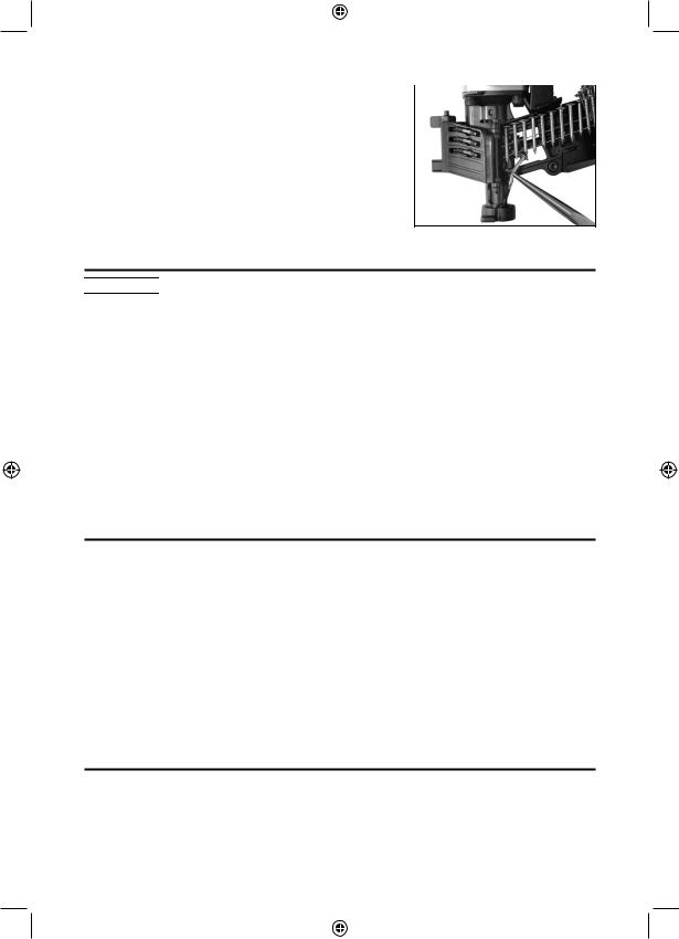
The BOSTITCH BRN175 is a precision-built tool, designed for high speed, high volume fastening. These tools will deliver efficient, dependable service when used correctly and with care. As with any fine tool, for best performance the manufacturer’s instructions must be followed. Please study this manual before operating the tool and understand the safety warnings and cautions. The instructions on installation, operation and maintenance should be read carefully, and the manual kept for reference. NOTE: Additional safety measures may be required because of your particular application of the tool. Contact your BOSTITCH representative or distributor with any questions concerning the tool and its use. BOSTITCH, 701 E. Joppa Road, Towson, Maryland 21286, U.S. & Canada Only, É.-U. et Canada seulement
INDEX
Safety instructions . . . . . . . . . . . . . . . . . . .3
Fastener specifications . . . . . . . . . . . . . . |
. |
. |
.4 |
Tool parts identification, trigger . . . . . . . . . . . |
. |
. |
.5 |
Loading the tool . . . . . . . . . . . . . . . . . |
|
6 & 7 |
|
Actuating the tool . . . . . . . . . . . . . . . . |
. |
. |
.8 |
Tool operation . . . . . . . . . . . . . . . . . |
. |
. |
.8 |
Adjusting depth . . . . . . . . . . . . . . . . . . . .9
Directional exhaust . . . . . . . . . . . . . . |
. . . . . . |
. . . . |
. . |
. . . . |
. . . . |
. .9 |
Clearing a jam . . . . . . . . . . . . |
. . |
. |
. . |
. . |
.10 |
|
Trouble shooting, tool specifications |
. . . |
. . |
. |
. . |
. . |
.13 |
NOTE:
BOSTITCH tools have been engineered to provide excellent customer satisfaction and are designed to achieve maximum performance when used with precision BOSTITCH fasteners engineered to the same exacting standards. BOSTITCH cannot assume responsibility for product performance if our tools are used with fasteners or accessories not meeting the specific requirements established for genuine BOSTITCH nails, staples and accessories.
LIMITED WARRANTY — U.S. and Canada Only
BOSTITCH Fastening Systems “BOSTITCH” warrants to the original retail purchaser that the product purchased is free from defects in material and workmanship, and agrees to repair or replace, at BOSTITCH’s option, any defective BOSTITCH branded pneumatic stapler or nailer for a period of seven (7) years from date of purchase (one (1) year from the date of purchase for compressors and tools used in production applications). Warranty is not transferable. Proof of purchase date required. This warranty covers only damage resulting from defects in material or workmanship; it does not cover conditions or malfunctions resulting from normal wear, neglect, abuse, accident or repairs attempted or made by other than our national repair center or authorized warranty service centers. Driver blades, bumpers, o-rings, pistons and piston rings are considered normally wearing parts. For optimal performance of your BOSTITCH tool always use genuine BOSTITCH fasteners and replacement parts.
THIS WARRANTY IS IN LIEU OF ALL OTHER WARRANTIES, EXPRESS OR IMPLIED, INCLUDING BUT NOT LIMITED TO THE IMPLIED WARRANTIES OF MERCHANTABILITY OR FITNESS FOR A PARTICULAR PURPOSE. BOSTITCH SHALL NOT BE LIABLE FOR ANY INCIDENTAL OR CONSEQUENTIAL DAMAGES.
Some states and countries do not allow limitations on how long an implied warranty lasts, or the exclusion or limitation of incidental or consequential damages, so the above limitations or exclusions may not apply to you. This warranty gives you specific legal rights, and you may also have other rights which vary from state to state and country to country. To obtain warranty service in the U.S. return the product, together with proof of purchase, to the U.S. BOSTITCH National or Regional Independent Authorized
Warranty Service Center. In the U.S. you may call us at 1-800-556-6696 or visit www.BOSTITCH.com for the location most convenient for you. In Canada please call us at 1-800-567-7705 or visit www.BOSTITCH.com.
2 - ENG
BRN175_9R209323_MAN_kf V2_multi.indd 2 |
|
|
1/28/15 7:41 AM |
|
|
DEFINITIONS - SAFETY GUIDELINES
When using any pneumatic tool, all safety precautions , as outlined below, should be followed to avoid the risk of death or serious injury. Read and understand the instructions before operating the tool. This manual contains information that is important for you to know and understand.This information relates to protecting YOUR SAFETY and PREVENTING EQUIPMENT PROBLEMS.To help you recognize this information, we use the symbols below. Please read the manual and pay attention to these symbols.
Indicates an imminently hazardous situation which, if not avoided, will result in death or serious injury.
Indicates a potentially hazardous situation which, if not avoided, could result in death or serious injury.
Indicates a potentially hazardous situation which, if not avoided, may result in minor or moderate injury.
Indicates a situation which, if not avoided, may result in property damage.
SAFETY INSTRUCTIONS
EYE PROTECTION which conforms to ANSI specifications and provides protection against flying particles both from the FRONT and SIDE should ALWAYS be worn by the operator and others in the work area when connecting to air supply, loading, operating or servicing this tool. Eye protection is required to guard against flying fasteners and debris, which could cause severe eye injury.
The employer and/or user must ensure that proper eye protection is worn. Eye protection equipment must conform to the requirements of the American National Standards Institute, ANSI Z87.1 and provide both frontal and side protection. NOTE: Non-side shielded spectacles and face shields alone do not provide adequate protection.
Additional Safety Protection will be required in some environments. For example, the working area may include exposure to noise level which can lead to hearing damage. The employer and user must ensure that any necessary hearing protection is provided and used by the operator and others in the work area. Some environments will require the use of head protection equipment. When required, the employer and user must ensure that head protection conforming to ANSI Z89.1 is used.
AIR SUPPLY AND CONNECTIONS
Do not use oxygen, combustible gases, or bottled gases as a power source for this tool as tool may explode, possibly causing injury.
never connect to a supply which can exceed 200 psi as tool may burst, possibly causing injury.
The connector on the tool must not hold pressure when air supply is disconnected. If a wrong fitting is used, the tool can remain charged with air after disconnecting and thus will be able to drive a fastener even after the air line is disconnected possibly causing injury.
Do not pull trigger or depress contact arm while connected to the air supply as the tool may cycle, possibly causing injury.
Always disconnect air supply: 1.) Before making adjustments; 2.) When servicing the tool; 3.) When clearing a jam; 4.) When tool is not in use; 5.) When moving to a different work area, as accidental actuation may occur, possibly causing injury.
LOADING TOOL
When loading tool: 1.) Never place a hand or any part of body in fastener discharge area of tool; 2.) Never point tool at anyone; 3.) Do not pull the trigger or depress the trip as accidental actuation may occur, possibly causing injury.
OPERATION
Always handle the tool with care: 1.) Never engage in horseplay; 2.) Never pull the trigger unless nose is directed toward the work; 3.) Keep others a safe distance from the tool while tool is in operation as accidental actuation may occur, possibly causing injury.
The operator must not hold the trigger pulled on contact arm tools except during fastening operation as serious injury could result if the trip accidentally contacted someone or something, causing the tool to cycle.
Keep hands and body away from the discharge area of the tool. A contact arm tool may bounce from the recoil of driving a fastener and an unwanted second fastener may be driven possibly causing injury.
3 - ENG
BRN175_9R209323_MAN_kf V2_multi.indd 3 |
|
|
1/28/15 7:41 AM |
|
|
Check operation of the contact arm mechanism frequently. Do not use the tool if the arm is not working correctly as accidental driving of a fastener may result. Do not interfere with the
proper operation of the contact arm mechanism.
Do not drive fasteners on top of other fasteners or with the tool at an overly steep angle as this may cause deflection of fasteners which could cause injury.
Do not drive fasteners close to the edge of the work piece as the wood may split, allowing the fastener to be deflected possibly causing injury.
This nailer produces SPARKS during operation. NEVER use the nailer near flammable substances, gases or vapors including lacquer, paint, benzine, thinner, gasoline, adhesives, mastics, glues or any other material that is -- or the vapors, fumes or byproducts of which are -- flammable, combustible or explosive.
Using the nailer in any such environment could cause an EXPLOSION resulting in personal injury or death to user and bystanders.
MAINTAINING THE TOOL
When working on air tools note the warnings in this manual and use extra care when evaluating problem tools.


 Use of this product may expose you to chemicals known to the State of California to cause cancer, birth defects and other reproductive harm.
Avoid inhaling vapors and dust, and wash hands after using.
•Avoid prolonged contact with dust from power sanding, sawing, grinding, drilling, and other construction activities. Wear protective clothing and wash exposed areas with soap and water. Allowing dust to get into your mouth, eyes, or lay on the skin may promote absorption of harmful chemicals.


 Use of this tool can generate and/or disburse dust, which may cause serious and permanent respiratory or other injury. Always use NIOSH/OSHA approved respiratory protection appropriate for the dust exposure. Direct particles away from face and body. Always operate tool in well-ventilated area and provide for proper dust removal. Use dust collection system wherever possible.


 ALWAYS USE SAFETY GLASSES. Everyday eyeglasses are NOT safety glasses. Also use face or dust mask if operation is dusty. ALWAYS WEAR CERTIFIED SAFETY EQUIPMENT:
•ANSI Z87.1 eye protection (CAN/CSA Z94.3),
•ANSI S12.6 (S3.19) hearing protection,
•NIOSH/OSHA respiratory protection.
Before operating this tool, carefully read and understand all instructions in
Important Safety Instructions.
|
SAVE THESE INSTRUCTIONS |
|
|
|
NAIL SPECIFICATIONS |
|
|
|
BRN175 |
Nails |
0.120" (3mm) diameter, 15º wire collated roofing nails |
Lengths |
3/4" (19 mm) - 1-3/4" (44.5 mm) |
|
|
Air Inlet |
1/4" NPT (6.4 mm) |
NOTE: Use |
only BOSTITCH approved fasteners |
|
4 - ENG |
BRN175_9R209323_MAN_kf V2_multi.indd 4 |
|
|
1/28/15 7:41 AM |
|
|
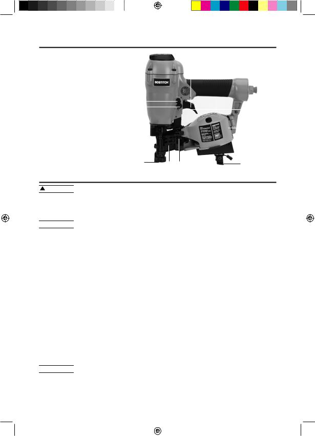
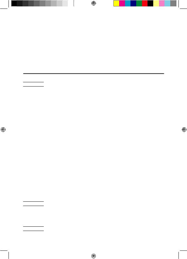
TOOL PARTS:
Fig. 1
A. |
Exhaust deflector |
|
|
|
|
|
|
|
|
A |
|
|
|
|
|
|
|
|
|
||||
|
|
|
|
|
|
B |
|||||
B. |
Selectable trigger |
|
|
|
|
|
|
||||
|
|
|
|
|
|
|
|
|
|
||
C. |
Canister |
|
|
|
|
|
|
|
|
|
|
D. |
Door latch |
|
|
|
|
|
|
|
|
|
|
E. |
Safety contact tip |
I |
|
|
|
|
|
|
|
|
|
F. |
Depth adjustment wheel |
|
|
|
|
|
|
|
|
||
|
|
|
|
|
|
||||||
J |
|
|
|
|
|
|
|
F |
|||
G. |
Door |
|
|
|
|
|
|||||
|
|
|
|
|
|
|
|
|
|||
|
|
|
|
|
|
|
|
|
|
||
H.Tool-Free Shingle Guide
I. Trigger lock button |
|
C |
|
J.Mode selector button
E |
G |
D |
H |
|
ASSEMBLY:


 Disconnect air line from tool, engage trigger lock and remove fasteners from magazine before making adjustments or personal injury may result.
TRIGGER


 Keep fingers AWAY from the trigger when not driving fasteners to avoid accidental actuation. Never carry a tool with finger on the trigger. In bump action mode (contact actuation mode), the tool will drive a fastener if the contact trip is bumped while the trigger is depressed.
The BRN175 is equipped with a selectable trigger.This trigger allows the operator to select either single sequential action trigger mode or bump action trigger mode. In accordance with the ANSI Standard SNT-101-2002, the trigger is assembled in the single sequential action trigger mode. To change the trigger mode, see Actuating Tool instructions in the Operation section of the manual. The selectable trigger also has a trigger lock button to keep the trigger locked at all times when the tool is not in use.
AIR FITTING
This tool uses a 1/4" N.P.T. male plug. The inside diameter should be .275" (7mm) or larger. The fitting must be capable of discharging tool air pressure when disconnected from the air supply. A 3/8" (9.5 mm) male quick connector coupling is available from BOSTITCH and may be used when a 1/4" (6.4 mm) supply line is not available.
NOTE: A 3/8" (9.5 mm) supply line (and fittings) are required for maximum tool performance.


 Always use couplings that relieve all pressure from the tool when it is disconnected from the power supply. Always use hose connectors that shut off air supply from compressor when the tool is disconnected.
5 - ENG
BRN175_9R209323_MAN_kf V2_multi.indd 5 |
|
|
1/28/15 7:41 AM |
|
|
To install an air fitting
1.Wrap the male end of the fitting with thread seal tape prior to assembly to eliminate air leaks.
2.To install a 1/4" (6.4 mm) fitting: screw it directly into the air inlet and tighten firmly. NOTE: If an adapter is in the air inlet, remove it prior to inserting the fitting.
3.To install a 3/8" (9.5 mm) fitting: screw the fitting into the 3/8" (9.5 mm) adapter and then into the air inlet of the tool and tighten firmly.
OPERATION:
PREPARING THE TOOL


 Read the section titled Important Safety Instructions for Pneumatic Tools at the beginning of this manual. Always wear eye and ear protection when operating this tool. Keep the nailer pointed away from yourself and others. For safe operation, complete the following procedures and checks before each use of the nailer.
 To reduce the risk of damage to the tool, only use BOSTITCH pneumatic tool oil or a non-detergent SAE 20 weight oil. Oil with additives or detergent will damage tool parts.
1.Before you use the nailer, be sure that the compressor tanks have been properly drained.
2.Lubricate tool:
a.Use BOSTITCH pneumatic tool oil or a non-detergent S.A.E. 20 weight oil. DO NOT use detergent oil or additives as they will damage O-rings and rubber parts.
b.Use a filter when possible.
c.Add 5 to 7 drops of oil in the air fitting a least twice a day.
3.Wear eye and ear protection.
4.Ensure canister is empty of all fasteners.
5.Check for smooth and proper operation of contact trip. Do not use tool if assembly is not functioning properly. NEVER tamper with the contact trip. NEVER use a tool that has the contact trip restrained in the actuated position.
6.Check air supply: Ensure air pressure does not exceed recommended operating limits; 70 to 120 psi, (4.9 to 8.3 bar, 5 to 8.5 kg/cm2).
7.Keep tool pointed away from yourself and others.
8.Connect air hose.
9.Check for audible leaks around valves and gaskets. Never use a tool that leaks or has damaged parts.


 To reduce the risk of personal injury, disconnect tool from air supply and engage trigger lock before performing maintenance, clearing a jammed fastener, leaving work area, moving tool to another location or handing the tool to another person.
LOADING THE TOOL (FIG. 1–6)


 Keep the tool pointed away from yourself and others. Serious personal injury may result.
6 - ENG
BRN175_9R209323_MAN_kf V2_multi.indd 6 |
|
|
1/28/15 7:41 AM |
|
|


 Never load nails with Fig. 2 the contact trip or trigger activated.
Personal injury may result.
1.Read all Safety Warnings before using tool.
2. |
Connect the air supply to the tool. |
E |
|||||||
3. |
Lift the canister door latch (E) to |
|
|
|
|
|
|||
|
|
|
|
|
|||||
|
open the nail guide door (H). |
|
|
|
|
|
|
||
4. |
Rotate the canister door (I) open. |
|
|
|
I |
||||
|
H |
|
|
|
|||||
5. |
Adjust the nail platform (J) to |
|
|
|
|||||
|
|
|
|
|
|||||
|
properly accommodate the |
nail |
|
|
|
|
|
||
|
length being used. Pull the nail platform (J) up or down for desired nail. |
||||||||
|
|
|
|
|
|
|
|
|
|
|
|
Platform Position |
|
|
Nail Length |
|
|
||
|
|
lowest position |
|
1-1/2" (38 mm) - 1 3/4" (44.5mm) |
|
|
|||
|
|
center position |
|
|
1-1/4" (32 mm) |
|
|
||
|
|
upper position |
|
3/4" (19 mm) - 1" (25 mm) |
|
|
|||
|
|
|
|
|
|
|
Fig. 3 |
|
J |
|
|
|
|
|
|
|
|
|
|
|
|
|
|
Fig. 4 |
K |
L |
Fig. 5 |
Fig. 6 |
E
|
|
H |
|
M |
|||
|
|
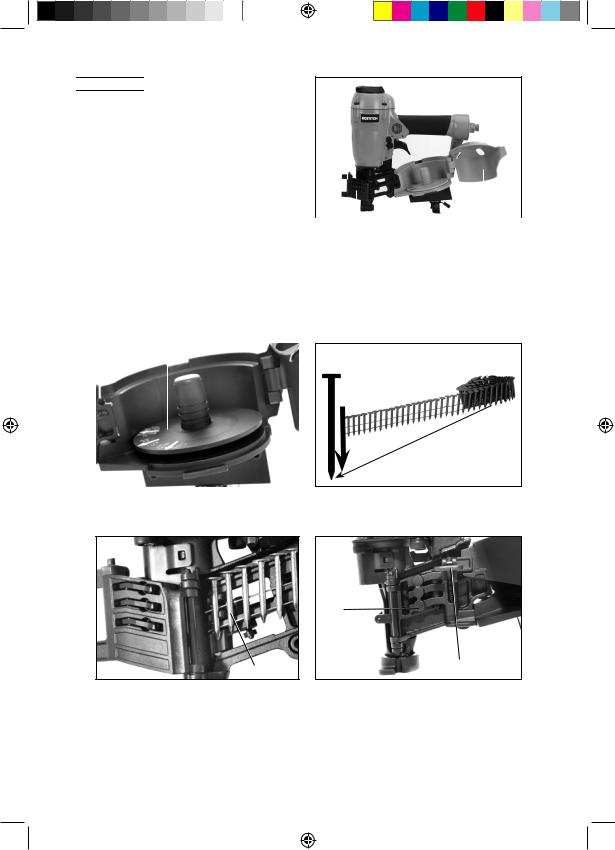
6.Place the coil on the nail platform (J). NOTE: Observe fastener icon (K) Fig. 4. Insert fasteners (L) with points down.
IMPORTANT: Fasteners must point in the same direction as they will be driven.
7.Uncoil enough nails [approximately 3" (76 mm)] to reach the nose of the tool.
8.Insert the first nail into the nose and the second nail (M) between the two rails of the feed pawl as shown in Fig. 5.
|
7 - ENG |
BRN175_9R209323_MAN_kf V2_multi.indd 7 |
1/28/15 7:41 AM |
NOTE: Be careful not to deform the coil of nails during the loading process. Otherwise, the nail guide door will not close and the nails might not feed consistently.
9. |
Close the canister door (I) completely. |
Trigger lock button |
|
10. |
Close the nail guide door (H) making sure the |
||
|
|||
|
door latch (E) is completely engaged as shown |
Fig. 7 |
|
|
in Fig. 6. |
||
|
|
ACTUATING TOOL: |
|
|
||
|
|
To reduce the risk of injury, ALWAYS |
|
|
|
|
|
||
|
|
|
||
wear proper eye ANSI Z87.1 (CAN/CSA Z94.3) |
S |
|||
and hearing protection ANSI S12.6 (S3.19) when |
|
|||
operating this tool. The tool can be actuated using |
|
|||
one of two modes: single sequential actuation |
|
|||
|
||||
trigger mode and contact actuation trigger mode. |
Trigger mode selector button |
|||
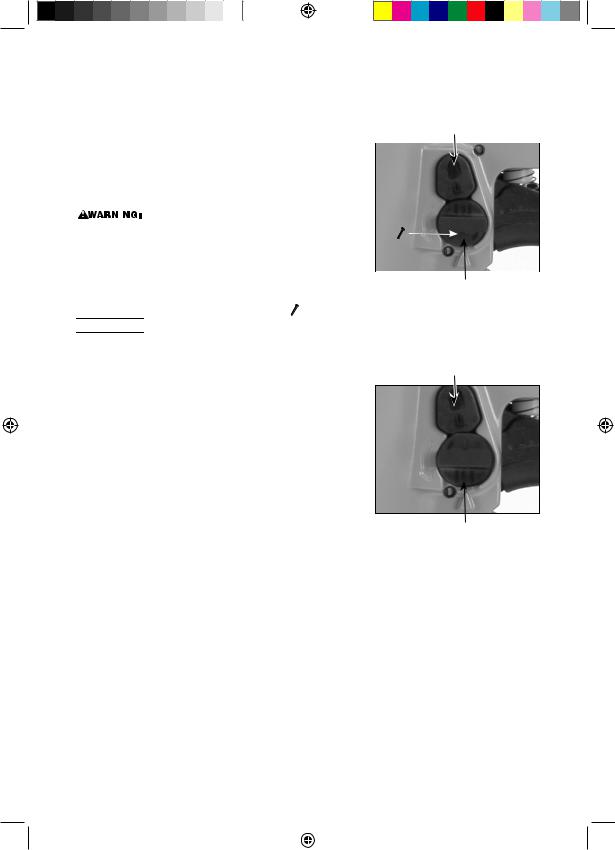
Single Sequential actuation trigger - |
(Fig. 7) |
|
||


 Allow the tool to recoil off the work surface after actuation. If the contact trip remains depressed a nail will be driven each time the trigger is released and pulled, which could result in accidental actuation, possibly causing injury.
The sequential actuation trigger’s intended use is for intermittent fastening where accurate fastener placement is desired.
To operate the tool in Single sequential actuation mode:
1.Depress the contact trip firmly against the work surface.
2.Pull the trigger.
3.Allow the tool to recoil from the work surface.
Contact actuation trigger -  (Fig. 8)
Fig. 8
C 

Trigger mode selector button
The contact actuation trigger is intended for rapid fastening on flat, stationary surfaces.
Using the contact actuation trigger, two methods are available: place actuation and contact actuation.
To operate the tool using the PLACE ACTUATION method:
1.Depress the contact trip against the work surface.
2.Pull the trigger to drive the fastener.
3.Allow the tool to recoil off the work surface
To operate the tool using the CONTACT ACTUATION method:
1.Pull the trigger.
2.Depress the contact trip against the work surface. As long as the trigger is pulled, the tool will drive a fastener every time the contact trip is depressed. This allows the user to rapidly drive multiple fastener in sequence.
8 - ENG
BRN175_9R209323_MAN_kf V2_multi.indd 8 |
|
|
1/28/15 7:41 AM |
|
|
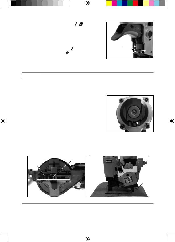
Changing the Actuation Mode - |
Fig. 9 |
1.Push the (red) trigger lock button down
2.Rotate the (black) selectable trigger button counterclockwise
3.Align the triangular indicator to the desired
mode |
G |
||
• |
For Sequential Mode |
||
|
|||
• |
For Contact Mode |
|
|
4.Then push the trigger lock button back up to the un-locked position.
ADJUSTING DEPTH (FIG. 9):


 To reduce risk of serious injury from accidental actuation when attempting to adjust depth, ALWAYS:
•Disconnect air supply and engage trigger lock.
•Avoid contact with trigger during adjustments.
The depth that the fastener is driven can be adjusted using the depth adjustment next to the trigger of the tool. The depth of drive Fig. 10
is factory adjusted to a nominal setting. Test drive a fastener and check depth. If a change is desired:
1.To drive the nail shallower, rotate the depth setting wheel (G) to the right.
2. To drive a nail deeper, rotate the depth setting |
A |
|
wheel (G) to the left. |
||
|
The adjustment knob has detents every 1/4 turn. Test drive another fastener and check depth.
Repeat as necessary to achieve desired results. The amount of air pressure required will vary depending on the size of the fastener and the material being fastened. Experiment with the air pressure setting to determine the lowest setting that will consistently perform the job at hand. Air pressure in excess of that required can cause premature wear and/or damage to the tool.
Fig. 11 |
P |
Fig. 12 |
||
|
|
|
|
|
|
O |
|
|
|
O
R
Q

DIRECTIONAL EXHAUST DEFLECTOR:
Adjust directional exhaust deflector (A) Fig. 10, so that the exhaust air blast will be directed away from the operator. The exhaust deflector can be adjusted any position for directing the exhaust blast away from the operator. Grasp the deflector and rotate it to the desired position for the current application.
9 - ENG
BRN175_9R209323_MAN_kf V2_multi.indd 9 |
|
|
1/28/15 7:41 AM |
|
|
|
|
|
|
|
|
|
|
|
|
|
|
|
|
|
|
|
|
|
|
|
|
|
|
|
|
|
|
|
|
|
|
|
|
|
|
|
|
|
|
|
|
|
|
|
|
|
|
|
|
|
|
|
|
|
|
|
|
|
|
|
|
|
|
|
|
|
|
|
|
|
|
|
|
|
|
|
|
|
|
SHINGLE GUIDE (FIG. 11, 12) |
|
|
|
|
|
|
|
|
|
|
|
||||||||||||
Fig. 13 |
|
|
|||||||||||||||||||||||
Adjust shingle guide (O):
1.Loosen the adjusting lever (P) and slide the locking plate to desired position.
2.Tighten adjusting lever firmly.
The locking plate (O) can be used as an aid to position the shingle being nailed a specific distance (Q) from the front edge of the previous row of shingles (R) as shown.
CLEARING A JAMMED NAIL (FIG. 1,9)


 Disconnect air line from tool, engage trigger lock lift the canister door latch, open the canister door, and remove fasteners from magazine before making adjustments or personal injury may result.
If a nail becomes jammed in the nosepiece, keep the tool pointed away from you and follow these instructions to clear:
1.Disconnect the air supply from the tool.
2.Engage trigger lock.
2.Lift the canister door latch (E) to open the nail guide door (H).
3.Open the canister door.
4.Remove the jammed nail.
5.Correct any deformation that may have occurred to the nail coil.
NOTE: Should nails continue to jam frequently in nosepiece, have tool serviced by an authorized BOSTITCH service center.
COLD WEATHER OPERATION
When operating tools at temperatures below freezing:
1.Make sure compressor tanks have been properly drained prior to use.
2.Keep tool as warm as possible prior to use.
3.Make certain all fasteners have been removed from canister.
4.Put 5 to 7 drops of BOSTITCH pneumatic tool oil in the air inlet.
5.Lower air pressure to 80 psi (5.5 bar) or less.
6.Reconnect air and load nails into canister.
7.Actuate the tool 5 or 6 times into scrap lumber to lubricate O-rings.
8.Turn pressure up to operating level (not to exceed 120 psi) and use tool as normal.
9.Re-lubricate at least once daily.
10.Always drain the compressor tanks at least once a day.
HOT WEATHER OPERATION
Tool should operate normally. However, keep tool out of direct sunlight as excessive heat can deteriorate bumpers, O-rings and other rubber parts resulting in increased maintenance.
10 - ENG
BRN175_9R209323_MAN_kf V2_multi.indd 10 |
|
|
1/28/15 7:41 AM |
|
|
MAINTENANCE:


 Disconnect air line from tool, engage trigger lock and remove fasteners from magazine before making adjustments or personal injury may
result.
DAILY MAINTENANCE CHART:
ACTION |
WHY |
HOW |
|
|
|
Lubricate tool with 5-7 |
Prevents failure |
Insert drops into air fitting |
drops of BOSTITCH |
of o-rings |
on end cap of tool |
PneumaticTool Oil |
|
|
Drain compressor |
Prevents |
Open petcocks or other drain |
tanks and hoses daily |
accumulation |
valves on compressor tanks. |
|
of moisture in |
Allow any accumulated |
|
compressor and nailer |
water to drain from hoses |
|
|
|
Clean canister, feed |
Permits smooth |
Blow clean with compressor |
piston area and contact |
operation of |
air.The use of oils, lubricants |
trip mechanism. |
magazine, |
periodically or solvents is |
|
reduces wear and |
not recommended as they |
|
prevents jams. |
tend to attract debris. |
|
|
|
Before each use, check |
Prevents jams, leaks |
Tighten loose screws |
to insure all screws, |
and premature |
or other fasteners using |
nuts and fasteners are |
failure of tool parts. |
the appropriate hex |
tight and undamaged. |
|
wrench or screwdriver. |
|
|
|
CLEANING
 Never use solvents or other harsh chemicals for cleaning the nonmetallic parts of the tool.These chemicals may weaken the materials used in these parts. Use a cloth dampened only with water and mild soap. Never let any liquid get inside the tool; never immerse any part of the tool into a liquid.
REPAIRS
For assistance with your tool, visit our website at www.bostitch.com for a list of service centers, or call the BOSTITCH Customer Care Center at 1-800-556-6696. In Canada please call us at 1-800-567-7705 or visit www.BOSTITCH.com.
SERVICE:
REPLACEMENT PARTS
Use only identical replacement parts. For a parts list or to order parts, visit our service website at http:/www.bostitch.com. You can also order parts from your nearest BOSTITCH Factory Service Center or BOSTITCH Authorized Warranty Service Center. Or, you can call our Customer Care Center at 1-800-556-6696. In Canada please call us at 1-800-567-7705 or visit www.BOSTITCH.com.
11 - ENG
BRN175_9R209323_MAN_kf V2_multi.indd 11 |
|
|
1/28/15 7:41 AM |
|
|

SERVICE AND REPAIRS
All quality tools will eventually require servicing and/or replacement of parts. For information about BOSTITCH, its factory service centers or authorized warranty service centers, visit our website at www.bostitch.com or you can call our Customer Care Center at 1-800-556-6696. In Canada please call us at 1-800-567-7705 or visit www.BOSTITCH.com. All repairs made by our service centers are fully guaranteed against defective material and workmanship. We cannot guarantee repairs made or attempted by others.
You can also write to us for information at BOSTITCH, 701 E. Joppa Road, Towson, Maryland 21286 - Attention: Product Service. Be sure to include all of the information shown on the nameplate of your tool (model number, type, serial number, etc.).
ACCESSORIES:
 Since accessories, other than those offered by BOSTITCH, have not been tested with this product, use of such accessories with this tool could be hazardous. To reduce the risk of injury, only BOSTITCH recommended accessories should be used with this product.
A complete line of accessories is available from your BOSTITCH Factory Service Center or a BOSTITCH Authorized Warranty Service Center. Please visit our Web Site www.bostitch.com for a catalog or for the name of your nearest supplier.
12 - ENG
BRN175_9R209323_MAN_kf V2_multi.indd 12 |
|
|
1/28/15 7:41 AM |
|
|
WARNING LABEL REPLACEMENT
If your warning labels become illegible or are missing, call 1-800-556-6696 for a free replacement. In Canada please call us at 1-800-567-7705 or visit www.BOSTITCH.com.
TROUBLE SHOOTING GUIDE:
MANY COMMON PROBLEMS CAN BE SOLVED EASILY BY UTILIZING THE CHART BELOW. FOR MORE SERIOUS OR PERSISTENT PROBLEMS, CONTACT A BOSTITCH SERVICE CENTER OR CALL 1-800-556-6696.


 To reduce the risk of serious personal injury, ALWAYS disconnect air from tool and engage trigger lock, before all repairs.
SYMPTOM |
PROBLEMS |
SOLUTIONS |
|
|
|
Air leak near |
Loose screws. |
Tighten screws. |
top of tool or in |
Worn or damaged |
Install Overhaul Kit. |
trigger area |
o-rings or seals. |
|
Tool does nothing or |
Inadequate air supply. |
Verify adequate air supply. |
operates sluggishly |
Inadequate lubrication. |
Put 5 or 7 drops of |
|
|
oil into air inlet. |
|
Worn or damaged |
Install Overhaul Kit. |
|
o-rings or seals. |
|
Air leak near |
Loose screws. |
Tighten screws. |
bottom of tool |
Worn or damaged |
Install Overhaul Kit. |
|
o-rings or bumper. |
|
Tool jams frequently |
Incorrect fasteners. |
Verify approved fasteners |
|
|
of correct size and 15° |
|
|
collation angle. |
|
Damaged fasteners. |
Replace with undamaged |
|
Bent collation wire. |
fasteners. |
|
Canister or nose |
Tighten screws. |
|
screws loose |
|
|
Canister is dirty. |
Clean magazine. |
|
Driver tip is worn |
Install Driver Maintenance Kit. |
|
or damaged. |
|
Other |
|
Contact a BOSTITCH |
|
|
Authorized Warranty |
|
|
Service Center |
TOOL SPECIFICATIONS |
|
|
BRN175 |
Height (inch/mm) |
10.63/ 270 |
|
|
Width (inch/mm) |
4.33/ 110 |
Length (inch/mm) |
10.24/ 260 |
|
|
Weight (lbs/kg) |
4.78/ 2.17 |
|
|
Recommended Operating Pressure |
70-120 psi (4.8 to 8.3 bar) |
Air Consumption per 100 cycles |
4.13 CFM |
|
|
Loading capacity |
120 nails |
13 - ENG
BRN175_9R209323_MAN_kf V2_multi.indd 13 |
|
|
1/28/15 7:41 AM |
|
|
INTRODUCCIÓN
Las BOSTITCH BRN175 es una herramienta construida con precisión, diseñada para la fijación de alta velocidad y de alto volumen. Estas herramientas ofrecen un servicio confiable y eficiente cuando se utilizan de la manera correcta y con cuidado. Al igual que con cualquier herramienta fina, deben observarse las instrucciones del fabricante para un mejor rendimiento. Estudie este manual antes de utilizar la herramienta y comprenda las advertencias y precauciones de seguridad. Las instrucciones de instalación, operación y mantenimiento deben leerse con atención y debe conservarse el manual para tener como referencia. NOTA: Pueden requerirse medidas adicionales de seguridad debido a las aplicaciones específicas de la herramienta. Contacte a su representante o distribuidor de BOSTITCH si tiene preguntas con respecto a la herramienta y su uso. BOSTITCH, 701 E. Joppa Road, Towson, Maryland 21286, EE. UU. y Canadá solamente, É.-U. et Canada seulement
ÍNDICE
Instrucciones de seguridad . . . . . . . . . . |
. . . . . |
. |
. |
. |
. |
3 |
Especificaciones de los clavos . . . . . . . . . |
. . . . . |
. |
. |
. |
. |
4 |
Identificación de partes de la herramienta, gatillo . . |
. . . . . |
. |
. |
. |
. |
5 |
Carga de la herramienta . . . . . . . . . . . |
. . . . . |
. |
. |
.6 & 7 |
||
Herramienta de accionamiento . . . . . . . . . |
. . . . . |
. . . . 8 |
||||
Funcionamiento . . . . . . . . . . . . . . . |
. . . . . |
. |
. |
. |
|
. 8 |
Ajuste de la profundidad . . . . . . . . . . . . . . . . . |
. . . . 9 |
||
Deflector de escape direccional . . . . . . . . . . |
. . . |
. |
. . . . 9 |
Eliminación de un clavo atascado . . . . . . . . . |
. . . . |
|
. . . . 10 |
Cuadro de mantenimiento diario, especificaciones de la herramienta . . . . . . 13
NOTA:
Las herramientas BOSTITCH han sido diseñadas para proporcionar una excelente satisfacción del cliente y están destinadas para alcanzar un máximo rendimiento cuando se usan con las fijaciones de precisión BOSTITCH, diseñadas con los mismos estándares de precisión. BOSTITCH no puede asumir la responsabilidad por el rendimiento del producto si nuestras herramientas se usan con fijaciones o accesorios que no cumplen los requisitos específicos establecidos para clavos, grapas y accesorios originales de BOSTITCH.
GARANTÍA LIMITADA - Solo EE. UU. y Canadá
Sistemas de fijación BOSTITCH “BOSTITCH” garantiza al comprador minorista original que el producto comprado está libre de defectos en material y mano de obra, y acepta reparar o reemplazar, a opción de BOSTITCH, toda grapadora o clavadora de marca BOSTITCH defectuosa por un período de siete (7) años desde la fecha de compra (y un [1] año desde la fecha de compra, en el caso de compresores y herramientas utilizados en aplicaciones de producción). La garantía no es transferible. Se requiere prueba de la fecha de compra. Esta garantía cubre únicamente daños derivados de defectos en el material o en la mano de obra; no cubre condiciones o averías resultantes del desgaste normal, negligencia, abuso, accidente o reparaciones que se hayan intentado o realizado a través de otro servicio que no sea el centro de reparación nacional o un centro de servicio de garantía autorizado. Las hojas de transmisión, protecciones, juntas tóricas, pistones y anillos del pistón se consideran piezas de desgaste normal. Para un rendimiento óptimo de su herramienta BOSTITCH, use siempre fijaciones y piezas de repuesto originales de BOSTITCH.
ESTA GARANTÍA REEMPLAZA TODA OTRA GARANTÍA, EXPRESA O IMPLÍCITA, QUE INCLUYE, ENTRE OTROS, LAS GARANTÍAS IMPLÍCITAS DE COMERCIABILIDAD O APTITUD PARA UN PROPÓSITO EN PARTICULAR. BOSTITCH NO SERÁ RESPONSABLE POR DAÑOS INCIDENTALES O RESULTANTES.
Algunos estados y países no permiten las limitaciones al plazo de una garantía implícita, o la exclusión o limitación de daños incidentales o resultantes, por lo que las limitaciones o exclusiones anteriores pueden no ser de aplicación para usted. Esta garantía le ofrece derechos legales específicos, y también puede tener otros derechos que pueden variar de un estado a otro y de un país a otro. Para obtener el servicio de garantía en los EE. UU., devuelva el producto, junto con el comprobante de compra, al Centro de servicio nacional de BOSTITCH en los EE. UU. o el centro de servicio de garantía
independiente regional autorizado. En los EE. UU., puede contactarnos al 1-800-556-6696 o visitar www.BOSTITCH. com para conocer la ubicación más conveniente para usted. En Canadá, contáctenos al 1-800-567-7705 o visite www.BOSTITCH.com.
14 - SP
BRN175_9R209323_MAN_kf V2_multi.indd 14 |
|
|
1/28/15 7:41 AM |
|
|
 Loading...