


BTFP72155 / BTFP72156
SMART POINTTM 15 GA Angled Finish Nailer
CLAVADORA NEUMÁTICA ANGULAR PARA CALIBRE
15 SMART POINT™
CLOUEUSE DE FINITION À ANGLE DE
CALIBRE 15 SMART POINTMC
OPERATION and MAINTENANCE MANUAL MANUAL DE OPERACIÓN Y DE MANTENIMIENTO MANUEL D’INSTRUCTIONS ET D’ENTRETIEN
BEFORE OPERATING THIS TOOL, ALL OPERATORS SHOULD STUDY THIS MANUAL TO UNDERSTAND AND FOLLOW THE SAFETY WARNINGS AND INSTRUCTIONS. KEEP THESE INSTRUCTIONS WITH THE TOOL FOR FUTURE REFERENCE. IF YOU HAVE ANY QUESTIONS, CONTACT YOUR BOSTITCH REPRESENTATIVE OR DISTRIBUTOR.
ANTES DE OPERAR ESTA HERRAMIENTA, TODOS LOS OPERADORES DEBERÁN ESTUDIAR ESTE MANUAL PARA PODER COMPRENDER Y SEGUIR LAS ADVERTENCIAS SOBRE SEGURIDAD Y LAS INSTRUCCIONES. MANTENGA ESTAS INSTRUCCIONES CON LA HERRAMIENTA PARA FUTURA REFERENCIA, SI TIENE ALGUNA DUDA, COMUNÍQUESE CON SU REPRESENTANTE DE BOSTITCH O CON SU DISTRIBUIDOR.
LIRE ATTENTIVEMENT LE PRÉSENT MANUEL AVANT D’UTILISER L’APPAREIL. PRÉTER UNE ATTENTION TOUTE PARTICULIÈRE AUX CONSIGNES DE SÉCURITÉ ET AUX AVERTISSEMENTS. GARDER CE MANUEL AVEC L’OUTIL POUR FUTUR RÉFÉRENCE. SI VOUS AVEZ DES QUESTIONS, CONTACTEZ VOTRE REPRÉSENTANT OU VOTRE CONCESSIONNAIRE BOSTITCH.
9R205731RA 11/13

INTRODUCTION
The BOSTITCH BTFP72155 & BTFP72156 are precision-built tools, designed for high speed, high volume fastening. These tools will deliver efficient, dependable service when used correctly and with care. As with any fine power tool, the manufacturer’s instructions must be followed for best performance. Please study this manual before operating the tool and understand the safety warnings and cautions. The instructions on installation, operation, and maintenance should be read carefully, and the manuals should be kept for reference. NOTE: Additional safety measures may be required because of your particular application of the tool. Contact your BOSTITCH representative or distributor with any questions concerning the tool and its use. BOSTITCH Fastening Systems, 701 E. Joppa Road, Towson, Maryland 21286, U.S. & Canada Only, É.-U. et Canada seulement.
INDEX
Safety Instructions . . . . . . . . . . . . . . . . . . . . . |
. |
. 3 |
Tool Components . . . . . . . . . . . . . . . . . . . . . |
. |
. 5 |
Tool Specifications . . . . . . . . . . . . . . . . . . . . . |
. |
6 |
Air Supply and Connections . . . . . . . . . . . . . . . . . . . 7 |
||
Loading the Tool . . . . . . . . . . . . . . . . . . . . . . . 8 |
||
Trigger Lockout & Selecting Trip Mode . . . . . . . . . . . . . |
. |
8-9 |
Dial-A-Depth® . . . . . . . . . . . . . . . . . . . . . . . . . 10 |
||
Installing the Belt Hook . . . . . . . . . . . . . . . . . . . |
. |
11 |
Tool Operation . . . . . . . . . . . . . . . . . . . . . . . |
. |
12 |
Jam Clearing Procedure . . . . . . . . . . . . . . . . . . |
. |
. 13 |
Maintaining the Pneumatic Tool . . . . . . . . . . . . . . . |
. |
. 14 |
Troubleshooting . . . . . . . . . . . . . . . . . . . . . . . 16 |
||
Available Accessories . . . . . . . . . . . . . . . . . . . . |
. |
17 |
NOTE:
BOSTITCH tools have been engineered to provide excellent customer satisfaction and are designed to achieve maximum performance when used with precision BOSTITCH fasteners engineered to the same exacting standards. BOSTITCH cannot assume responsibility for product performance if our tools are used with
fasteners or accessories not meeting the specific requirements established for genuine BOSTITCH nails, staples and accessories.
LIMITED WARRANTY — U.S. and Canada Only
BOSTITCH Fastening Systems (“BOSTITCH”) warrants to the original retail purchaser that the product purchased is free from defects in material and workmanship, and agrees to repair or replace, at BOSTITCH’s option, any defective BOSTITCH branded pneumatic stapler or nailer for a period of seven (7) years from date of purchase (one (1) year from the date of purchase for compressors and tools used in production applications). Warranty is not transferable. Proof of purchase date required. This warranty covers only damage resulting from defects in material or workmanship; it does not cover conditions or malfunctions resulting from normal wear, neglect, abuse, accident or repairs attempted or made by other than our national repair center or authorized warranty service centers. Driver blades, bumpers, o-rings, pistons and piston rings are considered normally wearing parts. For optimal performance of your BOSTITCH tool always use genuine BOSTITCH fasteners and replacement parts.
THIS WARRANTY IS IN LIEU OF ALL OTHER WARRANTIES, EXPRESS OR IMPLIED, INCLUDING BUT NOT LIMITED TO THE IMPLIED WARRANTIES OF MERCHANTABILITY OR FITNESS FOR A PARTICULAR PURPOSE. BOSTITCH SHALL NOT BE LIABLE FOR ANY INCIDENTAL OR CONSEQUENTIAL DAMAGES.
Some states and countries do not allow limitations on how long an implied warranty lasts, or the exclusion or limitation of incidental or consequential damages, so the above limitations or exclusions may not apply to you. This warranty gives you specific legal rights, and you may also have other rights which vary from state to state and country to country.
To obtain warranty service in the U.S. return the product, together with proof of purchase, to the U.S. BOSTITCH National or Regional Independent Authorized Warranty Service Center. In the U.S. you may call us at 1-800-556- 6696 or visit www.BOSTITCH.com for the location most convenient for you. In Canada please call us at 1-800-567- 7705 or visit www.BOSTITCH.com
-2-
save these instructions
DEFINITIONS - SAFETY GUIDELINES
This manual contains information that is important for you to know and understand. This information relates to protecting YOUR SAFETY and PREVENTING EQUPMENT PROBLEMS. To help you recognize this information, we use the symbols below. Please read the manual and pay attention to these symbols.
Indicates an imminently hazardous situation which, if not avoided, will result in death or serious injury.
Indicates a potentially hazardous situation which, if not avoided, could result in death or serious injury.
Indicates a potentially hazardous situation which, if not avoided, may result in minor or moderate injury.


 Indicates a situation which, if not avoided, may result in property damage.
SAFETY INSTRUCTIONS
EYE PROTECTION which conforms to ANSI specifications and provides protection against flying particles both from the FRONT and SIDE should ALWAYS be worn by the operator and others in the work area when connecting to air supply, loading, operating or servicing this tool. Eye protection is required to guard against flying fasteners and debris, which could cause severe eye injury.
The employer and/or user must ensure that proper eye protection is worn. Eye protection equipment must conform to the requirements of the American National Standards Institute, ANSI Z87.1 and provide both frontal and side protection. NOTE: Non-side shielded spectacles and face shields alone do not provide adequate protection.
CAUTION: Additional Safety Protection will be required in some environments. For example, the working area may include exposure to noise level which can lead to hearing damage. The employer and user must ensure that any necessary hearing protection is provided and used by the operator and others in the work area. Some environments will require the use of head protection equipment. When required, the employer and user must ensure that head protection conforming to ANSI Z89.1 is used.
Some dust created by power sanding, sawing, grinding, drilling, and other construction activities contains chemicals known to the State of California to cause cancer, birth defects or other reproductive harm. Some examples of these chemicals are:
• lead from lead-based paints
• crystalline silica from bricks and cement and other masonry products
• arsenic and chromium from chemically-treated lumber.
Your risk from these exposures varies, depending on how often you do this type of work. To reduce your exposure to these chemicals: work in a well ventilated area, and work with approved safety equipment, such as those dust masks that are specially designed to filter out microscopic particles.
AIR SUPPLY AND CONNECTIONS
Do not use oxygen, combustible gases, or bottled gases as a power source for this tool as tool may explode, possibly causing injury.
Do not use supply sources which can potentially exceed 200 P.S.I.G. as tool may burst, possibly causing injury.
The connector on the tool must not hold pressure when air supply is disconnected. If a wrong fitting is used, the tool can remain charged with air after disconnecting and thus will be able to drive a fastener even after the air line is disconnected possibly causing injury.
Do not pull trigger or depress contact arm while connected to the air supply as the tool may cycle, possibly causing injury.
Always disconnect air supply: 1.) Before making adjustments; 2.) When servicing the tool; 3.) When clearing a jam; 4.) When tool is not in use; 5.) When moving to a different work area, as accidental actuation may occur, possibly causing injury.
-3-

LOADING TOOL
When loading tool: 1.) Never place a hand or any part of body in fastener discharge area of tool; 2.) Never point tool at anyone; 3.) Do not pull the trigger or depress the trip as accidental actuation may occur, possibly causing injury.
OPERATION


 This tool operates differently from all other BOSTITCH tools. To provide maximum visibility for accurate fastener placement, the trip of this tool is normally in the “depressed” or “up” position. On all other BOSTITCH tools and most other tools, the trip is normally in the “down” position.
This tool has a selectable trigger mode which determines if the tool drives fasteners in sequential or contact mode. In sequential trip mode, when the tip of the nose is placed on the work surface and the trigger is pulled, the trip moves out from the tool to detect the work surface. The tool nose tip must be in contact with the work surface to actuate. If the trip does not detect the work surface close enough to the nose of the tool, the tool will not actuate.
In contact trip mode, when the trigger is depressed and held, the trip will move out from the tool. Contacting the work surface with the tool nose, will actuate the trip mechanism driving a fastener each time the work surface is contacted.
Always handle the tool with care: 1.) Never engage in horseplay; 2.) Never pull the trigger unless nose is directed toward the work; 3.) Keep others a safe distance from the tool while tool is in operation as accidental actuation may occur, possibly causing injury.
The operator must not hold the trigger pulled on contact arm tools except during fastening operation as serious injury could result if the trip accidentally contacted someone or something, causing the tool to cycle.
Keep hands and body away from the discharge area of the tool. A contact arm tool may bounce from the recoil of driving a fastener and an unwanted second fastener may be driven possibly causing injury.
Check operation of the contact arm mechanism frequently. Do not use the tool if the arm is not working correctly as accidental driving of a fastener may result. Do not interfere with the proper operation of the contact arm mechanism.
Do not drive fasteners on top of other fasteners or with the tool at an overly steep angle as this may cause deflection of fasteners which could cause injury.
Do not drive fasteners close to the edge of the work piece as the wood may split, allowing the fastener to be deflected possibly causing injury.
This nailer produces SPARKS during operation. NEVER use the nailer near flammable substances, gases or vapors including lacquer, paint, benzine, thinner, gasoline, adhesives, mastics, glues or any other material that is -- or the vapors, fumes or by-products of which are -- flammable, combustible or explosive. Using the nailer in any such environment could cause an EXPLOSION resulting in personal injury or death to user and bystanders.
MAINTAINING THE TOOL
If the tool has been dropped or you suspect tool damage perform tool operation check as defined in the tool operation check section.
When working on air tools note the warnings in this manual and use extra care when evaluating problem tools.
-4-

TOOL COMPONENTS
|
|
|
|
|
|
|
|
|
|
|
|
|
|
Over-Molded |
Rear Exhaust |
|
Frame Cap |
|
|
|
|
|
|
|
|
|
|
|
|
Comfort Grip |
|
||
|
|
|
|
|
|
|
|
|
|
|
|
|
|
|
||
Frame Protector |
|
|
|
|
|
|
|
|
|
|
|
|
|
|
||
|
|
|
|
|
|
|
|
|
|
|
|
|
|
|||
Frame |
|
|
|
|
|
|
|
|
|
|
|
|
|
Trigger |
|
|
|
|
|
|
|
|
|
|
|
|
|
|
|||||
Trigger Lockout |
|
|
|
|
|
|
|
|
|
|
|
|||||
|
|
|
|
|
|
|
|
|
|
|
|
|
||||
Actuation Mode |
|
|
|
|
|
|
|
|
|
|
||||||
Selector Switch |
|
|
|
|
|
|
|
|
|
Belt Hook |
||||||
|
|
|
|
|
|
|
|
|
|
|
|
|
|
|
|
|
|
|
Latch |
|
|
|
|
|
|
|
|
|
|
|
Dial-A-Depth® |
||
|
|
|
|
|
|
|
|
|
|
|
|
|
||||
|
|
|
|
|
|
|
|
|
|
|
|
|
|
|
|
|
|
|
|
|
|
|
|
|
|
|
|
|
|
|
|
|
Control |
|
Nose Door |
|
|
|
|
|
|
|
|
Contact Trip |
|
|||||
|
|
|
|
|
|
|
|
|
|
|||||||
|
|
|
|
|
|
|
|
|
|
|
|
|
|
|
||
|
|
|
|
|
|
|
|
|
|
|
|
|
|
|
||
Trigger
Lockout
P e n c i l |
|
|
No-Mar Tip |
|
|
||
Sharpener |
|
|
|
|
Spare No Mar Tip Storage |
||
|
|||
-5-

TOOL SPECIFICATIONS
All dimensions in inches unless otherwise specified. |
|
|
|
|
|
|
BTFP72155 |
BTFP72156 |
Description |
DA15 GA Angled Finish Nailer |
FN15 GA Angled Finish Nailer |
Engine Type |
Oil-Free |
Oil-Free |
Operation Pressure Range |
70-120 PSI (4.9 to 8.43kg/cm2) |
70-120 PSI (4.9 to 8.43kg/cm2) |
Maximum Operation Pressure |
120 PSI (8.43 kg/cm2) |
120 PSI (8.43 kg/cm2) |
Fastener Type |
DA15 Series |
FN15 Series |
Fastener Gauge |
15 Gauge |
15 Gauge |
Fastener Range |
1-1/4” - 2-1/2” (31mm - 63mm) |
1-1/4” - 2-1/2” (31mm - 63mm) |
Magazine Capacity |
100 |
129 |
Length |
12.8” (325mm) |
14.3” (363mm) |
Width |
3.8” (97mm) |
3.8” (97mm) |
Height |
12.1” (307mm) |
12.1” (307mm) |
Weight |
4.22lbs (1.9kg) |
4.32lbs (2.0kg) |
Operating Pressure:
70 to 120 p.s.i.g. (4.9 to 8.43 kg/cm2). Select the operating pressure within in this range for best fastener performance.
DO NOT EXCEED THIS RECOMMENDED OPERATING PRESSURE.
Air Consumption:
The BTFP72155 requires 1.8 cubic feet per minute or C.F.M. (51.0 liters per minute or LT/MIN) of free air at 80 PSI (5.6 kg/cm2) to operate at a rate of 60 fasteners per minute. The BTFP72156 requires 1.9 cubic feet per minute or C.F.M. (53.8 liters per minute or LT/MIN) of free air at 80 PSI (5.6 kg/cm2) to operate at a rate of 60 fasteners per minute.
To determine the appropriately sized air compressor, take the actual rate at which the tool will be run and compare the required C.F.M. (LT/MIN) to the compressors free air delivery (C.F.M./ LT/MIN) at 80 PSI (5.6 kg/cm2).
For example, if your fastener usage averages 30 fasteners per minute, you need 50% of the tools C.F.M. required to operate the tool at the rate of 60 fasteners per minute. In this case, be sure that your air compressor can deliver a minimum of 0.9 C.F.M. (25.5 LT/MIN) at 80 PSI(5.6 kg/cm2) for optimum performance of the BTFP72155.
FASTENER SPECIFICATIONS
Tool Model |
Fastener Type |
Fastener SKU |
Crown Width |
Gauge |
Length |
|
|
|
|
|
|
|
|
|
|
DA1520 |
N/A |
15 |
1-1/4” (32mm) |
|
BTFP72155 |
|
DA1524 |
N/A |
15 |
1-1/2” (38mm) |
|
DA Type |
|
|
|
|
||
DA1532 |
N/A |
15 |
2” (50mm) |
|||
|
Angled Finish |
|||||
|
|
|
|
|
||
|
Nails |
DA1540 |
N/A |
15 |
2-1/2” (63mm) |
|
|
|
|
|
|
|
|
|
|
|
|
|
|
|
|
|
FN1520 |
N/A |
15 |
1-1/4” (32mm) |
|
|
|
FN1524 |
N/A |
15 |
1-1/2” (38mm) |
|
BTFP72156 |
|
FN1528 |
N/A |
15 |
1-3/4” (45mm) |
|
|
|
FN1532 |
N/A |
15 |
2” (50mm) |
|
|
Angled |
|||||
|
Finish Nails |
|
|
|
|
|
|
FN1536 |
N/A |
15 |
2-1/4” (57mm) |
||
|
|
FN1540 |
N/A |
15 |
2-1/2” (63mm) |
* Stainless steel fasteners also available in certain sizes. Visit www.BOSTITCH.com for further details.
-6-

NOTE:
BOSTITCH tools have been engineered to provide superior customer satisfaction and are designed to achieve maximum perfomance when used with precision BOSTITICH fasteners engineered to the same exacting standards. BOSTITCH cannot assume responsibility for product performance if our tools are used with fasteners or accessories not meeting the specific requirements established for genuine BOSTITCH fasteners and accessories.
AIR SUPPLY AND CONNECTIONS
Do not use oxygen, combustible gases, or bottled gases as a power source for this tool as tool may explode, possibly causing injury.
FITTINGS:
Install a male plug on the tool which is free flowing and which will release air pressure from the tool when disconnected from the supply source.
HOSES:
Air hoses should have a minimum of 150 p.s.i. (10.6 kg/cm2) working pressure rating or 150 percent of the maximum pressure that could be produced in the air system. The supply hose should contain a fitting that will provide “quick disconnecting” from the male plug on the tool.
SUPPLY SOURCE:
Use only clean regulated compressed air as a power source for this tool. NEVER USE OXYGEN, COMBUSTIBLE GASES, OR BOTTLED GASES, AS A POWER SOURCE FOR THIS TOOL AS TOOL MAY EXPLODE.
REGULATOR:
A pressure regulator with an operating pressure of 0 - 125 p.s.i. (0 - 8.79 kg/cm2) is required to control the operating pressure for safe operation of this tool. Do not connect this tool to air pressure which can potentially exceed 200 p.s.i. (14 kg/cm2) as tool may fracture or burst, possibly causing injury.
OPERATING PRESSURE:
Do not exceed recommended maximum operating pressure as tool wear will be greatly increased. The air supply must be capable of maintaining the operating pressure at the tool. Pressure drops in the air supply can reduce the tool’s driving power. Refer to “TOOL SPECIFICATIONS” for setting the correct operating pressure for the tool.
FILTER:
Dirt and water in the air supply are major causes of wear in pneumatic tools. A filter will help to get the best performance and minimum wear from the tool. The filter must have adequate flow capacity for the specific installation. The filter has to be kept clean to be effective in providing clean compressed air to the tool. Consult the manufacturer’s instructions on proper maintenance of your filter. A dirty and clogged filter will cause a pressure drop which will reduce the tool’s performance.
Quick Connect Plug
Quick Disconnect Plug
-7-

LOADING THE TOOL
EYE PROTECTION which conforms to ANSI specifications and provides protection against flying particles both from the FRONT and SIDE should ALWAYS be worn by the operator and others in the work area when connecting to air supply, loading, operating or servicing this tool. Eye protection is required to guard against flying fasteners and debris, which could cause severe eye injury.
The employer and/or user must ensure that proper eye protection is worn. Eye protection equipment must conform to the requirements of the American National Standards Institute, ANSI Z87.1 and provide both frontal and side protection. NOTE: Non-side shielded spectacles and face shields alone do not provide adequate protection.
TO PREVENT ACCIDENTAL INJURIES:
•Never place a hand or any other part of the body in nail discharge area of tool while the air supply is connected.
•Never point the tool at anyone else.
•Never engage in horseplay.
•Never pull the trigger unless nose is directed at the work.
•Always handle the tool with care.
•Do not pull the trigger or depress the trip mechanism while loading the tool.
LOADING THE BTFP72155/BTFP72156
The BTFP72155/BTFP72156 nailers are equipped with dual load purpose magazines. Nails can be loaded in either method.
LOAD AND PULL PUSHER
1.Load nails through the slot in the rear of the magazine to past retaining clip.
2.Pull pusher back behind nail stick and release.
3.Ensure magazine pusher is behind the last nail stick.
4.Blow the magazine clean periodically to keep the pusher moving smoothly and to keep dirt and debris out of the nail channel.
.
PULL PUSHER TO LOCK BACK AND LOAD
1.Pull pusher back until it is locked at the end of magazine.
2.Load nails through the slot in the rear of the magazine and past retaining clip.
3.Press the pusher button to release and allow the pusher to push behind the nails.
4.Blow the magazine clean periodically to keep the pusher moving smoothly and to keep dirt and debris out of the nail channel.
-8-

TRIGGER LOCKOUT CONTROL
The trigger lockout control feature on BOSTITCH pneumatic tools provides a trigger lock feature for added safety control. Push the lockout control button in or out to activate or lock the tool trigger.
Trigger Lockout
Control Button
TRIP OPERATION MODE
Always disconnect air supply before making adjustments as accidental actuation may occur, possibly causing injury.
The BTFP72155/BTFP72156 feature a selectable trigger system that allows the user to choose between the following modes of operation:
1. Contact Trip Operation |
2. Sequential Trip Operation |
1. CONTACT TRIP:
The common operation procedure on “Contact Trip” tools is for the operator to contact the work surface to actuate the trip mechanism while keeping the trigger pulled, thus driving a fastener each time the work
surface is contacted. This will allow rapid fastener placement on many jobs. All pneumatic tools are subject to recoil when driving fasteners. The tool may bounce, releasing the trip, and if unintentionally allowed to re-contact the work surface with the trigger still actuated (finger still holding the trigger pulled) an unwanted second fastener will be driven.
2. SEQUENTIAL TRIP:
The Sequential Trip requires the operator to hold the tool against the work before pulling the trigger. This makes accurate fastener placement easier. The Sequential Trip allows exact fastener location without the possibility if driving a second fastener on recoil as described under “Contact Trip”. The Sequential Trip Tool has a positive advantage because it will not accidentally drive a fastener if the tool is contacted against the work surface - or anything else - while the operator is holding the trigger pulled.
-9-

SELECTING THE TRIP MODE:
To ensure safety, the user must lock the trigger (as described above) before changing the trigger system. To change the trip mode, rotate the mode switch toward the body of the tool. The mode switch will lock automatically when the indicating arrow is pointing down to the 3 nail icon stamped into the tool frame (Contact Trip Mode) or to a single nail icon stamped in the tool frame( Sequential Trip Mode). Unlock the trigger to resume tool operation.
Sequential Trip Mode
(trip mode selector switch pointing up)
Contact Trip Mode
(trip mode selector switch pointing down)
DIAL-A-DEPTH® FASTENER CONTROL ADJUSTMENT
The DIAL-A-DEPTH® Fastener control adjustment feature provides close control of the fastener drive depth: from flush with the work surface to shallow or deep countersink. First set the air pressure for consistent drive in the specific work as described on page 7, then use the DIAL-A-DEPTH® fastener control adjustment to give the desired depth of drive.
Dial-A-Depth® Fastener
Control Adjustment
IN ADDITION TO THE OTHER WARNINGS CONTAINED IN THIS MANUAL OBSERVE THE FOLLOWING FOR SAFE OPERATION
•Use the BOSTITCH pneumatic tool only for the purpose for which it was designed.
•Never use this tool in a manner that could cause a fastener to be directed toward the user or others in the work area.
•Do not use the tool as a hammer.
•Always carry the tool by the handle. Never carry the tool by the air hose.
•Do not alter or modify this tool from the original design or function without approval from
BOSTITCH.
•Always be aware that misuse and improper handling of this tool can cause injury to yourself and others.
•Never clamp or tape the trigger or contact trip in an actuated position.
•Never leave a tool unattended with the air hose attached.
•Do not operate this tool if it does not contain a legible WARNING LABEL.
•Do not continue to use a tool that leaks air or does not function properly. Notify your nearest
BOSTITCH representative if your tool continues to experience functional problems.
-10-
BELT HOOK
Always disconnect tool from air supply before making adjustments or before attempting any part assembly or disassembly.


 The belt hook can not be removed.
The Bostitch BTFP72155 & BTFP72156 include an integrated belt hook and can be rotated to either side of the tool to accommodate leftor righthanded users. It can also be rotated out of the
way when not in use.
1 |
|
|
2 |
|
|
3 |
|
|
|
|
|
|
|
|
|
USING THE INTEGRATED PENCIL SHARPENER
A standard pencil sharpener is integrated into the magazine for the operator’s convenience. To sharpen a pencil, insert any standard pencil into the hole and rotate the pencil to the right (clockwise) to sharpen.
INTEGRATED AIR BLOWER
NEVER blow debris toward yourself to others in the work area.
BTFP72155 & BTFP72156 have an integrated air blower that helps clean debris while working. Press the integrated air blower button. Compressed air will be ejected out from front of the tool. Released the button to stop blowing air.
-11-

16“ O.C. GAUGE
16” O.C. gauge helps to indicate stud location.
1.Pull up the O.C. gauge to rotate to the opposite side.
2.Press on the O.C. gauge to snap into the magazine.
3.16“ is measured from nose to the tip of O.C. gauge to help find stud.
16“
TOOL OPERATION
EYE PROTECTION which conforms to ANSI specifications and provides protection against flying particles both from the FRONT and SIDE should ALWAYS be worn by the operator and others in the work area when connecting to air supply, loading, operating or servicing this tool. Eye protection is required to guard against flying fasteners and debris, which could cause severe eye injury.
The employer and/or user must ensure that proper eye protection is worn. Eye protection 


 equipment must conform to the requirements of the American National Standards Institute, ANSI Z87.1 and provide both frontal and side protection. NOTE: Non-side shielded
spectacles and face shields alone do not provide adequate protection.
BEFORE HANDLING OR OPERATING THIS TOOL:
I.READ AND UNDERSTAND THE WARNINGS CONTAINED IN THIS MANUAL.
II.REFER TO “TOOL SPECIFICATIONS” IN THIS MANUAL TO IDENTIFY THE OPERATING SYSTEM ON YOUR TOOL.
OPERATION
1. CONTACT TRIP OPERATION:
In CONTACT TRIP MODE the tool contains a contact trip that operates in conjunction with the trigger to drive a fastener. There are two methods of operation to drive fasteners with a contact trip tool.
A.SINGLE FASTENER PLACEMENT: To operate the tool in this manner, first position the contact trip on the work surface, WITHOUT PULLING THE TRIGGER. Hold the nose against the work surface and then pull the trigger to drive a fastener. Do not press the tool against the work with extra force. Instead, allow the tool to recoil off the work surface to avoid a second unwanted fastener. Remove your finger from the trigger after each operation.
B.RAPID FASTENER OPERATION: To operate the tool in this manner, hold the tool with the contact trip pointing towards but not touching the work surface. Pull the trigger and then tap the contact trip against the work surface using a bouncing motion. Each depression of the contact trip will cause a fastener to be driven.
The operator must not hold the trigger pulled on contact trip tools except during fastening operation, as serious injury could result if the trip accidentally contacts someone or something, causing the tool to cycle.
Keep hands and body away from the discharge area of the tool. A contact trip tool may bounce from the recoil of driving a fastener and an unwanted second fastener may be driven, possibly causing injury.
2. SEQUENTIAL TRIP OPERATION:
In SEQUENTIAL TRIP MODE the contact trip operates in conjunction with the trigger to drive a fastener. To operate a sequential trip tool, first position the contact trip on the work surface WITHOUT PULLING THE TRIGGER. Hold the nose against the work surface and then pull the trigger to drive a fastener. As long as the contact trip is contacting the work and is held depressed, the tool will drive a fastener each time the trigger is depressed. If the contact trip is allowed to leave the work surface, the sequence described above must be repeated to drive another fastener.
-12-
This tool operates differently from all other BOSTITCH tools. To provide maximum visibility for accurate fastener placement, the trip of this tool is normally in the “depressed” or “up” position. On all other BOSTITCH tools and most other tools, the trip is normally in the “down” position.
This tool has a selectable trigger mode which determines if the tool drives fasteners in sequential or contact mode. In sequential trip mode, when the tip of the nose is placed on the work surface and the trigger is pulled, the trip moves out from the tool to detect the work surface. The tool nose tip must be in contact with the work surface to actuate. If the trip does not detect the work surface close enough to the nose of the tool, the tool will not actuate.
In contact trip mode, when the trigger is depressed and held, the trip will move out from the tool. Contacting the work surface with the tool nose, will actuate the trip mechanism driving a fastener each time the work surface is contacted.
If the tool has been dropped or you suspect tool damage perform tool operation check as  defined in the tool operation check section.
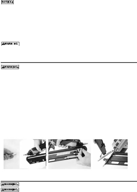
Jam Clearing Procedure
Disconnect tool from air supply before making adjustments or before attempting any part assembly or disassembly.
On occasion nails can jam in the nose of a pneumatic nailer. This can be caused by striking a metal plate in the wall, drywall screw, or some other hard object. The BTFP72155/BTFP72156 features open drive channel architecture for jam clearing. To clear a jam follow this procedure:
1.Disconnect the tool from the air supply.
2.Release the pusher so it is no longer applying force to the nail sticks.
3.Open the jam clearing nose door by pulling down and then up on the latch.
4.Remove the jammed fastener. In certain circumstances, pliers may be required to remove the fastener.
5.Close the jam clearing nose door latch.
6.Pull nail pusher back behind nail sticks.
7.Perform tool operation check.
BTFP72155/BTFP72156 Jam Clearing
1 |
|
2 |
|
3 |
|
|
|
|
|
TOOL OPERATION CHECK
Always remove all fasteners from tool before performing tool operation check. if the tool is dropped or you suspect tool damage perform tool operation check.
-13-

1.CONTACT TRIP OPERATION:
A.With finger off the trigger, press the contact trip against the work surface.
THE TOOL MUST NOT CYCLE.
B.Hold the tool off the work surface, and pull the trigger.
THE TOOL MUST NOT CYCLE.
C.With the tool off the work surface, pull the trigger. Press the contact trip against the work surface.
THE TOOL MUST CYCLE.
D.Without touching the trigger, press the contact trip against the work surface, then pull the trigger.
THE TOOL MUST CYCLE.
2.SEQUENTIAL TRIP OPERATION:
A.Press the contact trip against the work surface, without touching the trigger.
THE TOOL MUST NOT CYCLE.
B.Hold the tool off the work surface and pull the trigger.
THE TOOL MUST NOT CYCLE.
C.Pull the trigger and press the contact trip against the work surface.
THE TOOL MUST NOT CYCLE.
D.With finger off the trigger, press the contact trip against the work surface. Pull the trigger.
THE TOOL MUST CYCLE.
MAINTAINING THE PNEUMATIC TOOL
When working on air tools, note the warnings in this manual and use extra care evaluating problem tools.
REPLACEMENT PARTS:
Use only genuine BOSTITCH replacement parts. Do not use modified parts.
ASSEMBLY PROCEDURE FOR SEALS:
When repairing a tool, make sure the internal parts are clean and lubricated. Use Parker “O”-LUBE, Magnalube, or equivalent on all “O”-rings. Coat each “O”-ring with lubricant before assembling.
AIR SUPPLY-PRESSURE AND VOLUME:
Air volume is as important as air pressure. The air volume supplied to the tool may be inadequate because of undersize fittings and hoses, or from the effects of dirt and water in the system. Restricted air flow will prevent the tool from receiving an adequate volume of air, even though the pressure reading is high. The results will be slow operation, misfeeds or reduced driving power. Before evaluating tool problems for these symptoms, trace the air supply from the tool to the supply source for restrictive connectors, low points containing water and anything else that would prevent full volume flow of air to the tool.
-14-

Maintenance Checklist
Maintenance |
Benefit |
Procedure |
Service Interval |
|
|
|
|
Inspect trigger performance |
Ensure trigger system is in |
Refer to Tool Operation |
Daily |
|
proper working order |
Check section in this manual |
|
|
|
|
|
Drain condensation from air |
Prevents accumlation of |
Open drain cock on tanks |
Daily |
compressor tanks and air |
moisture that can impede tool |
and air filters and drain all |
|
filters daily or after each use. |
performace |
condensate |
|
|
|
|
|
Clean magazine assembly |
Prevents accumlation of |
Blow clean with compressed air |
Daily |
|
debris that could cause a jam |
|
|
|
|
|
|
Clean nose, door, and |
Prevents accumulation of |
Blow clean with compressed air |
Daily |
contact arm area |
debris that could cause a jam |
|
|
|
or malfunction |
|
|
|
|
|
|
Ensure all fasteners remain |
Prevent loose parts |
Tighten all fasteners with |
Weekly |
tight |
|
appropriately sized hex |
|
|
|
wrench |
|
|
|
|
|
Check/clean air inlet air filter |
Maintains proper air flow to |
Remove end cap and use |
25,000 Fasteners, or monthly |
|
engine for peak performance. |
compressed air blow gun to |
- if used in dusty location |
|
|
blow filter clean. Replace filter |
|
|
|
as required. |
|
Replace no-mar tip |
Prevents marks in softwood |
Remove worn no-mar tip and |
25,000 Fasteners |
|
applications |
replace with a new tip (a spare tip |
|
|
|
is located on the magazine) |
|
|
|
|
|
Replace piston/driver |
Maintains consistent drive |
Refer to replacement part kit |
150,000 Fasteners |
assembly |
quality |
instructions |
|
|
|
|
|
Replace O-rings |
Maintains engine for peak |
Refer to replacement part kit |
250,000 Fasteners |
|
performance |
instructions |
|
|
|
|
|
Replace bumper |
Maintains engine for peak |
Refer to replacement part kit |
250,000 Fasteners |
|
performance |
instructions |
|
|
|
|
|
Replace headvalve |
Maintains engine for peak |
Refer to replacement part kit |
250,000 Fasteners |
|
performance |
instructions |
|
|
|
|
|
Replace engine cylinder |
Maintains engine for peak |
Refer to replacement part kit |
500,000 Fasteners |
|
performance |
instructions |
|
|
|
|
|
-15-
 Loading...