

Bosch Greenstar combi 100 p, Greenstar combi 151 p, ZWB28-3A NG, ZWB28-3A LPG, ZWB42-3A NG Installation And Service Instructions For Contractors
...
WAR NI NG :
Improper installation, set-up, modification, operation or maintenance
of the heating system can cause personal injury and property damage.
Follow these instructions precisely.
If you require assistance or further information, contact a trained and
certified installer or the gas supply company.
WAR NI NG :
The operating instructions are part of the technical documents that
must be handed over to the owner or operator of the heating system.
Explain to the owner or operator how to use the heating system using
the operating instructions. Make sure that they are familiar with all
required information for the safe and proper operation of the heating
system.
These instructions are available in English and French.
Please keep these instructions for future reference.
0010004900-002
Residential Gas Condensing Boiler
Greenstar combi 100 p / 151 p
ZWB28-3A... | ZWB42-3A...
Installation and Service Instructions for Contractors
6720872361 (2017/04) US/CA

2 | Contents
Contents
1 Explanation of symbols and safety instructions. . . . . . . . . . . . 3
1.1 Explanation of symbols . . . . . . . . . . . . . . . . . . . . . . . . . . . 3
1.2 General safety instructions. . . . . . . . . . . . . . . . . . . . . . . . 4
2 Scope of delivery. . . . . . . . . . . . . . . . . . . . . . . . . . . . . . . . . . . . . . 5
3 Product Description . . . . . . . . . . . . . . . . . . . . . . . . . . . . . . . . . . . 5
3.1 Proper use . . . . . . . . . . . . . . . . . . . . . . . . . . . . . . . . . . . . . 5
3.2 Overview of boiler types . . . . . . . . . . . . . . . . . . . . . . . . . . 5
3.3 Rating plate . . . . . . . . . . . . . . . . . . . . . . . . . . . . . . . . . . . . 5
3.4 Appliance description . . . . . . . . . . . . . . . . . . . . . . . . . . . . 6
3.5 Accessories . . . . . . . . . . . . . . . . . . . . . . . . . . . . . . . . . . . . 6
3.6 Product dimensions and minimum clearances . . . . . . . . 7
3.7 ZWB..-3A appliance layout . . . . . . . . . . . . . . . . . . . . . . . . 8
3.8 Electrical wiring . . . . . . . . . . . . . . . . . . . . . . . . . . . . . . . . 10
3.9 Technical data . . . . . . . . . . . . . . . . . . . . . . . . . . . . . . . . . 11
3.10 Condensate composition . . . . . . . . . . . . . . . . . . . . . . . . 13
4 Regulations . . . . . . . . . . . . . . . . . . . . . . . . . . . . . . . . . . . . . . . . . 13
4.1 Compliance with standards and regulations . . . . . . . . . 13
4.2 Operating limits of the boiler . . . . . . . . . . . . . . . . . . . . . 14
4.3 Additional regulations for installations in the
Commonwealth of Massachusetts . . . . . . . . . . . . . . . . . 14
7 Electrical connection . . . . . . . . . . . . . . . . . . . . . . . . . . . . . . . . . 32
7.1 General notes . . . . . . . . . . . . . . . . . . . . . . . . . . . . . . . . . 32
7.2 Low voltage electrical connections in the
Heatronic boiler control . . . . . . . . . . . . . . . . . . . . . . . . . 32
7.2.1 Open the Heatronic boiler control . . . . . . . . . . . . . . . . . 32
7.2.2 Connecting the outdoor temperature sensor
(accessory) . . . . . . . . . . . . . . . . . . . . . . . . . . . . . . . . . . . 33
7.2.3 Connecting additional accessories . . . . . . . . . . . . . . . . 33
7.3 Connecting power supply. . . . . . . . . . . . . . . . . . . . . . . . 34
7.4 Connecting the LWCO device . . . . . . . . . . . . . . . . . . . . . 35
8 Commissioning . . . . . . . . . . . . . . . . . . . . . . . . . . . . . . . . . . . . . . 36
8.1 Before operating the appliance . . . . . . . . . . . . . . . . . . . 37
8.2 Switching the appliance ON/OFF. . . . . . . . . . . . . . . . . . 37
8.3 Switch on heat. . . . . . . . . . . . . . . . . . . . . . . . . . . . . . . . . 37
8.4 Setting the DHW temperature . . . . . . . . . . . . . . . . . . . . 37
8.5 Setting manual summer mode . . . . . . . . . . . . . . . . . . . . 38
8.6 Setting frost protection. . . . . . . . . . . . . . . . . . . . . . . . . . 38
8.7 Activating the key pad lock. . . . . . . . . . . . . . . . . . . . . . . 38
9 Boiler circulator. . . . . . . . . . . . . . . . . . . . . . . . . . . . . . . . . . . . . . 39
9.1 Pump anti-seize protection. . . . . . . . . . . . . . . . . . . . . . . 39
9.2 Changing the pump curve of the boiler pump . . . . . . . . 39
5 Examples of Installations . . . . . . . . . . . . . . . . . . . . . . . . . . . . . . 15
5.1 Multiple zones using zone valves with DHW. . . . . . . . . . 15
5.2 Multiple zones using circulators with DHW . . . . . . . . . . 17
6 Notes on installation and operation . . . . . . . . . . . . . . . . . . . . . 19
6.1 Notes on installation and operation . . . . . . . . . . . . . . . . 19
6.1.1 Important notes. . . . . . . . . . . . . . . . . . . . . . . . . . . . . . . . 19
6.1.2 Other important information . . . . . . . . . . . . . . . . . . . . . 20
6.2 Selecting an external expansion vessel . . . . . . . . . . . . . 20
6.3 Selecting the installation location . . . . . . . . . . . . . . . . . 20
6.4 Pre-installing pipes . . . . . . . . . . . . . . . . . . . . . . . . . . . . . 21
6.5 Mounting the appliance. . . . . . . . . . . . . . . . . . . . . . . . . . 22
6.6 Installing the low water cut off (LWCO) . . . . . . . . . . . . . 23
6.7 Connecting flue gas accessories . . . . . . . . . . . . . . . . . . 23
6.7.1 Installation of the exhaust and air intake system. . . . . . 24
6.7.2 Examples of approved horizontal and vertical
venting installation . . . . . . . . . . . . . . . . . . . . . . . . . . . . . 28
6.7.3 Vent and combustion air pipe lengths . . . . . . . . . . . . . . 30
6.8 Testing gas and water connections for leaks . . . . . . . . . 31
10 Heatronic boiler control settings . . . . . . . . . . . . . . . . . . . . . . . 39
10.1 Guideline to service functions . . . . . . . . . . . . . . . . . . . . 39
10.2 Overview of the service functions . . . . . . . . . . . . . . . . . 40
10.2.1 Service-level 1 (Press and hold the service button
until it lights up) . . . . . . . . . . . . . . . . . . . . . . . . . . . . . . . 40
10.2.2 Second service level (at first service level, service
button lights up, press ECO button and key pad
lock button simultaneously until 8.A appears) . . . . . . . 40
10.3 Description of the service functions . . . . . . . . . . . . . . . 40
10.3.1 First service level. . . . . . . . . . . . . . . . . . . . . . . . . . . . . . . 40
10.3.2 Second service level . . . . . . . . . . . . . . . . . . . . . . . . . . . . 44
11 Gas adjustment . . . . . . . . . . . . . . . . . . . . . . . . . . . . . . . . . . . . . . 45
11.1 Converting to a different gas type . . . . . . . . . . . . . . . . . 45
11.2 Installation location higher than 2000 feet
(610 m) above sea level . . . . . . . . . . . . . . . . . . . . . . . . . 46
11.3 Checking and setting the gas-air ratio (CO2 or
O2), if required . . . . . . . . . . . . . . . . . . . . . . . . . . . . . . . . 46
11.4 Dynamic gas pressure test port . . . . . . . . . . . . . . . . . . . 47
12 Flue gas test . . . . . . . . . . . . . . . . . . . . . . . . . . . . . . . . . . . . . . . . . 48
12.1 Emissions test button . . . . . . . . . . . . . . . . . . . . . . . . . . . 48
12.2 Measuring CO content of flue gas. . . . . . . . . . . . . . . . . . 48
13 Environmental protection and disposal. . . . . . . . . . . . . . . . . . 48
Greenstar combi 100 p / 151 p6720872361 (2017/04)

Explanation of symbols and safety instructions | 3
14 Inspection and maintenance . . . . . . . . . . . . . . . . . . . . . . . . . . . 48
14.1 Description of various steps. . . . . . . . . . . . . . . . . . . . . . 49
14.1.1 Calling up the latest fault (service function 6.A). . . . . . 49
14.1.2 Fresh water filter in the cold water pipe. . . . . . . . . . . . . 49
14.1.3 Plate-type heat exchanger . . . . . . . . . . . . . . . . . . . . . . . 49
14.1.4 Checking electrodes . . . . . . . . . . . . . . . . . . . . . . . . . . . . 50
14.1.5 Burner servicing . . . . . . . . . . . . . . . . . . . . . . . . . . . . . . . 51
14.1.6 Heat exchanger block inspection and cleaning. . . . . . . 51
14.1.7 Cleaning condensate trap. . . . . . . . . . . . . . . . . . . . . . . . 53
14.1.8 Checking the mixer diaphragm . . . . . . . . . . . . . . . . . . . 53
14.1.9 Checking the expansion vessel . . . . . . . . . . . . . . . . . . . 53
14.1.10 Setting the boiler water pressure . . . . . . . . . . . . . . . . . 53
14.1.11 Testing system water quality . . . . . . . . . . . . . . . . . . . . . 53
14.1.12 Checking the electrical wiring . . . . . . . . . . . . . . . . . . . . 53
14.2 Maintenance and inspection checklist. . . . . . . . . . . . . . 54
15 Readings on the display . . . . . . . . . . . . . . . . . . . . . . . . . . . . . . . 55
16 Faults. . . . . . . . . . . . . . . . . . . . . . . . . . . . . . . . . . . . . . . . . . . . . . . 56
16.1 Troubleshooting . . . . . . . . . . . . . . . . . . . . . . . . . . . . . . . 56
16.2 Faults that are shown on the display . . . . . . . . . . . . . . . 56
16.3 Faults that are not shown on the display . . . . . . . . . . . . 58
16.4 Check sensor values . . . . . . . . . . . . . . . . . . . . . . . . . . . . 59
16.4.1 Outdoor temperature sensor (available as
accessory). . . . . . . . . . . . . . . . . . . . . . . . . . . . . . . . . . . . 59
16.4.2 Additional supply temperature limiter . . . . . . . . . . . . . . 59
16.4.3 Supply temperature sensor, DHW temperature
sensor, external supply temperature sensor. . . . . . . . . 59
16.5 Replacement code plug . . . . . . . . . . . . . . . . . . . . . . . . . 59
17 Commissioning log for the appliance. . . . . . . . . . . . . . . . . . . . 60
1 Explanation of symbols and safety instructions
1.1 Explanation of symbols
Warnings
In warnings, signal words at the beginning of a warning are used to
indicate the type and seriousness of the ensuing risk if measures for
minimizing danger are not taken.
The following keywords are defined and can be used in this document:
DANGER:
DANGER indicates a hazardous situation which, if not avoided, could
result in death or serious injury.
WARNING:
WARNING indicates a hazardous situation which, if not avoided, could
result in death or serious injury.
CAUTION:
CAUTION indicates a hazardous situation which, if not avoided, could
result in minor to moderate injury.
NOTICE:
NOTICE is used to address practices not related to personal injury.
Important Information
The info symbol indicates important information where there is no risk to
people or property.
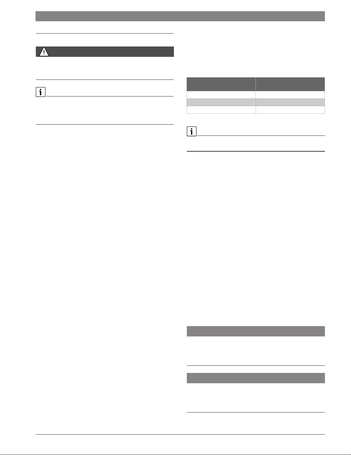
Additional symbols
Symbol Explanation
▶ Sequence of steps
Cross-reference to another part of the document
• Listing/list entry
– Listing/list entry (2nd level)
Table 1
6720872361 (2017/04)Greenstar combi 100 p / 151 p

4 | Explanation of symbols and safety instructions
1.2 General safety instructions
If you hear gas leaking!
▶ Leave the building immediately.
▶ Prevent others from entering the building.
▶ Notify the police and fire department from outside the building.
▶ From outside the building, call the gas supply company and a trained
and certified installer or service company.
HIf you smell gas
▶ Turn off the gas shut-off valve.
▶ Open windows and doors.
▶ Do not touch any electrical switch, telephone, and do not use outlets.
▶ Extinguish all open flames.
▶ Do not smoke!
▶ Do not use lighters!
▶ Warn all occupants of the building, but do not ring any bell.
▶ From outside the building, call the gas supply company and a trained
and certified installer or service company.
If you smell flue gas!
▶ Switch off the heating system by shutting off the emergency shut-off
switch.
▶ Open windows and doors.
▶ Call a trained and certified installer or service company.
DANGER: Risk of fatal injury from failing to consider your own
safety!
▶ Never risk your own life. Your own safety must always take the highest
priority
NOTICE: Risk of appliance damage from improper operation of the
boiler!
▶ Only use the boiler for its intended purpose.
▶ Only operate the boiler if it has been installed and maintained per the
instructions provided in the Installation Manual.
▶ Do not attempt to operate an appliance if any part of it is not in
working order or is damaged.
▶ Use only original spare parts! The use of parts not supplied by the
manufacturer may cause damage to the boiler, other property and
personal injury. Also, boiler damage caused by the use of
unauthorized parts is not covered by the warranty.
DANGER: Risk of fire when soldering and brazing!
▶ Take appropriate protective measures when soldering and brazing
around combustible and flammable material.
NOTICE:
▶ The installation must comply with all applicable national, state, and
local codes, rules, and regulations.
▶ The operator is responsible for the operational safety and regulatory
compliance of the heating system.
DANGER: Risk of personal injury or death from flue gas poisoning!
▶ Do not install a thermostatic flue gas damper downstream of the draft
hood.
▶ Do not tamper with, remove, or attempt to repair the blocked vent
switch.
▶ When replacing the blocked vent switch, install the new part in the
original location.
▶ A blocked vent switch tripping more than once indicates a problem
with the venting system or chimney which must be repaired
immediately.
▶ Ensure none of the vent pipes and chimneys are damaged or blocked.
▶ Connect only one appliance to each venting system or chimney.
▶ The venting system must not feed into or route through another air
extraction duct.
▶ The venting system must be inspected annually. All parts that show
any signs of damage or corrosion must be replaced.
▶ Never close off or reduce the size of the combustion air openings.
▶ The boiler must not be operated until any obstructions have been
removed.
DANGER: Risk of personal injury or death from explosion!
▶ Work on gas components may only be carried out by a trained and
certified installer or service company.
▶ Appliance installation, the connection of gas and vent piping, initial
commissioning, electrical connections, and service and
maintenance must only be carried out by a trained and certified
installer or service company.
DANGER: Risk of personal injury or death from fire!
▶ Do not use flammable or combustible material in the boiler room.
▶ It is recommended not to store any items within 16 inches (415mm)
of the appliance
CAUTION: Appliance damage from contaminated combustion air!
▶ Keep the combustion air free of corrosive substances, e.g.
halogenated hydrocarbons from painting operations or beauty
salons.
▶ Keep combustion air free from dust and lint, e.g. from laundry or
agricultural operations.
▶ If clean room air is not available, fresh outdoor combustion air must
be provided
DANGER: Risk of personal injury or death from electric shock!
▶ Before removing the front panel, disconnect the heating system from
the electrical power supply by shutting off the emergency shutoff
switch or the heating system circuit breaker.
▶ It is not enough to switch off the control panel. Power to the panel
must be disconnected! Ensure that the power is not restored
unintentionally by following proper lock out/tag out procedures.
▶ Only qualified electricians are permitted to carry out electrical work.
DANGER: Safety devices!
▶ Never shut off safety valves!
▶ Hot water may escape from the safety valve at any time when the
appliance is running.
DANGER: Risk of personal injury or death after a flood!
▶ Do not attempt to operate an appliance if any part of it has been under
water.
▶ An appliance that was subject to flooding must be replaced.
Greenstar combi 100 p / 151 p6720872361 (2017/04)
NOTICE:
▶ Upon completion of the installation, these instructions should be
handed to the owner and operator of the appliance.
▶ The installer must instruct the owner and operator on the
functionality of the components and the proper operation of the
boiler and the heating system.
▶ The boiler must be serviced annually including the main burner,
ignition burner, the entire venting system, and the combustion air
supply. All parts that show any signs of damage or corrosion must be
replaced.
2 Scope of delivery
1
Scope of delivery | 5
3 Product Description
ZWB appliances are residential combi boilers for central heating and on
demand DHW heating.
The appliances comply with South Coast Air Quality Management
District (SCAQMD) 2012 requirements: (Type-1) 14 Ng/J NO
20 ppm at 3 % O
).
2
3.1 Proper use
The Greenstar boiler is not for use in CSD-1 commercial installation.
The appliance may only be installed in closed loop hot water central
heating systems.
Any other purpose is considered improper use. Any resulting damage is
excluded from the manufacturer's warranty.
The commercial and industrial use of the appliance for generating
process heat is not permitted.
(and/or
x
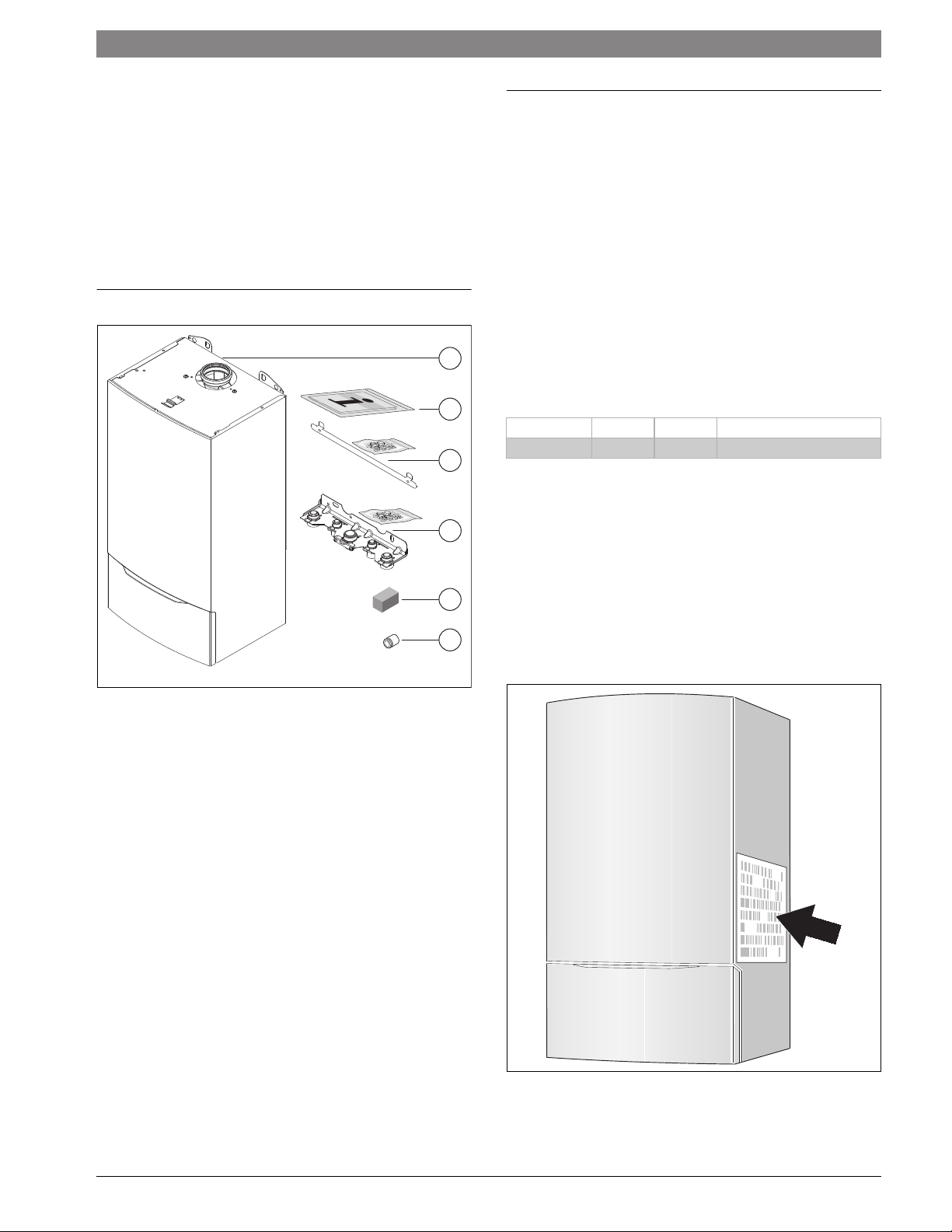
Fig. 1 Scope of delivery combi boiler ZWB..-3A
[1] Gas condensing boiler
[2] Set of documents for appliance
[3] Mounting bracket with mounting kit
[4] Hydraulics connection plate with mounting kit
[5] Gas conversion kit
[6] Adapter for connection of a LWCO
0010014673-001
2
3
4
5
6
3.2 Overview of boiler types
ZWB28-3 A 23 Greenstar combi 100 p
ZWB42-3 A 23 Greenstar combi 151 p
Table 2 Appliance types
Z Central heating appliance
W DHW heating
B Condensing technology
28 Output and DHW output up to 95,500 BTU/hr (28 kW)
42 Output and DHW output up to 143,300 BTU/hr (42 kW)
-3 Version
A Fan-supported appliance
23 Natural gas (NG)
3.3 Rating plate
The rating plate is located at the right side of the appliance.
6 720 641 933-84.2O
Fig. 2 Data plate location
The rating plate contains the appliance output, model number, approval
data and serial number.
6720872361 (2017/04)Greenstar combi 100 p / 151 p

6 | Product Description
3.4 Appliance description
• Appliance for wall installation, regardless of chimney and room size
• Intelligent boiler pump control
• Heatronic boiler control with 2-wire BUS
• Three-speed boiler circulator
• Automatic air vent
• Display
• Automatic ignition
• Continuously-controlled output
• Full protection via the Heatronic with flame rod and solenoid valves
• No minimum circulating water flow rate required
• Suitable for radiant floor heating
• Flue adapter for flue gas and combustion air with test ports
• Variable speed fan
• Gas premix burner
• Temperature sensor and temperature control for space heating
• Supply temperature sensor
• Temperature limit sensor
• Safety relief valve, pressure gauge
• Flue gas temperature limiter
• DHW priority switching
• Motorized 3-way valve
• Hydraulics connection plate
3.5 Accessories
Here you will find a list of typical accessories for this appliance. Refer to
the Product Catalog for a complete overview of all available accessories.
• Adapter for separate pipe routing USA Chapter 6.7, page 23. This
adapter is needed for connection of standard PVC vent pipes.
• Concentric flue gas accessories Chapter 6.7, page 23. This flue
gas accessory is used for concentric flue gas routing.
• Neutralizer NBT-23 - condensing (part number 7 738 005 514)
• Neutralizing agent for neutralizer NBT-23 (part number
7 738 005 515)
• Cleaning blade for WB-5 (accessory number 1061, part number
7 719 002 503)
• Cleaning brush kit for WB-5 (accessory number 1060, part number
7 719 002 502)
• Supply temperature sensor (part number 8 737 700 289 0)
• Bosch remote control CRC 100 (part number 7 738 110 090): The
CRC 100 is a comfort-enhancing room thermostat for measuring the
room temperature and automatic adjustment to the desired room
temperature. Optional combination with CZM 100 and CRC 200.
• Bosch remote control CRC 200 (part number 7 738 111 034): The
CRC 200 is a largely programmable room thermostat for measuring
the room temperature and automatic adjustment to the desired room
temperature. Optional combination with CZM 100 and CRC 100.
• Bosch Zone module CZM 100 (part number 7 738 110 112): The
CZM 100 is an expansion module for several heating zones with
valves or pumps. Optional combination with CRC 100 and CRC 200.
• Bosch remote control FW 200 USA (part number 8 718 226 215 0):
weather-compensated heating controller. Optional combination with
ICM 100.
• Cascade module ICM 100 (part number 7 719 003 528): The
ICM 100 makes it possible to increase the total output of the system
through use of several heat sources. Optional combination with
FW 200.
Greenstar combi 100 p / 151 p6720872361 (2017/04)
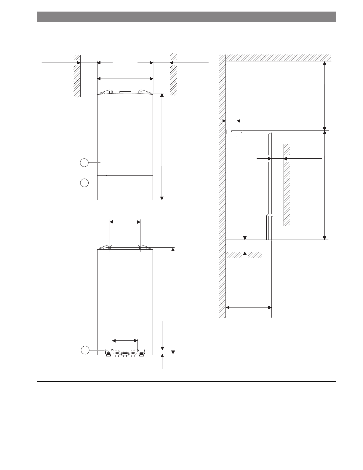
3.6 Product dimensions and minimum clearances
Product Description | 7
≥ 4" *
(102 mm) *
1
2
17-21/64"
(440 mm)
9-29/64"
(240 mm)
(102 mm) *
(850 mm)
33-15/32"
≥ 4" *
3-11/32"
(85 mm)
≥ 4" **
(102 mm) **
≥ 15"
(381 mm)
(862 mm)
33-15/16"
(849 mm)
33-27/64"
7-7/8"
(200 mm)
1-3/16"
(30 mm)
3
Fig. 3 Dimensions and minimum clearances (front view, rear view, side view)
[1] Outer jacket complete
[2] Front cover
[3] Hydraulics connection plate
(*) Zero clearance from combustibles permitted, but 4" (102 mm)
recommended for serviceability
(**) Distance to door, if mounted inside a closet
≥ 4" *
(102 mm) *
13-57/64"
(353 mm)
0010004928-001
6720872361 (2017/04)Greenstar combi 100 p / 151 p
8 | Product Description
3.7 ZWB..-3A appliance layout
28
29
27
26
25
24
23
30
31
32
22
33
21
34
20
19
35
18
36
17
16
15
14
37
38
39
13
40
41
42
43
1
12
2
3
4
11
10
9
44
5
n
i
m
6
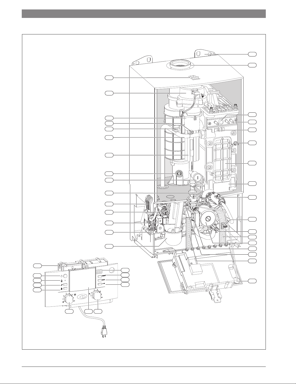
Fig. 4 ZWB..-3A appliance layout
8
7
6 720 641 933-03.2O
Greenstar combi 100 p / 151 p6720872361 (2017/04)

Key to Fig. 4:
[1] Heatronic
[2] ON/OFF power switch
[3] Burner operation indicator lamp
[4] Service button
[5] Emissions test button
[6] Boiler high limit dial
[7] Mounting socket for outdoor reset controls
[8] DHW thermostat
[9] Key pad lock
[10] ECO button
[11] Reset button
[12] Display
[13] Condensate trap
[14] Test ports for inlet gas pressure
[15] Adjustment screw, minimum gas volume
[16] DHW temperature sensor
[17] Plate-type heat exchanger
[18] Automatic air vent
[19] Maximum gas adjuster
[20] Flue gas temperature limiter
[21] Combustion air intake
[22] Supply pipe
[23] Connection for optional low water cut off (LWCO)
[24] Additional supply temperature limiter
[25] Gas/air premix chamber
[26] Fan
[27] Bracket
[28] Wall hanging bracket
[29] Exhaust pipe
[30] Flame viewing window
[31] Set of electrodes complete
[32] Supply temperature sensor
[33] Boiler block temperature limiter
[34] Inspection and cleanout cover
[35] Condensate collector
[36] Flow meter
[37] 3-way valve
[38] Drain cock
[39] Condensate drain hose
[40] Boiler circulator
[41] Pump speed switch
[42] Pressure relief valve (heating zone)
[43] Safety relief valve discharge hose
[44] Boiler water pressure gauge
Product Description | 9
6720872361 (2017/04)Greenstar combi 100 p / 151 p
10 | Product Description
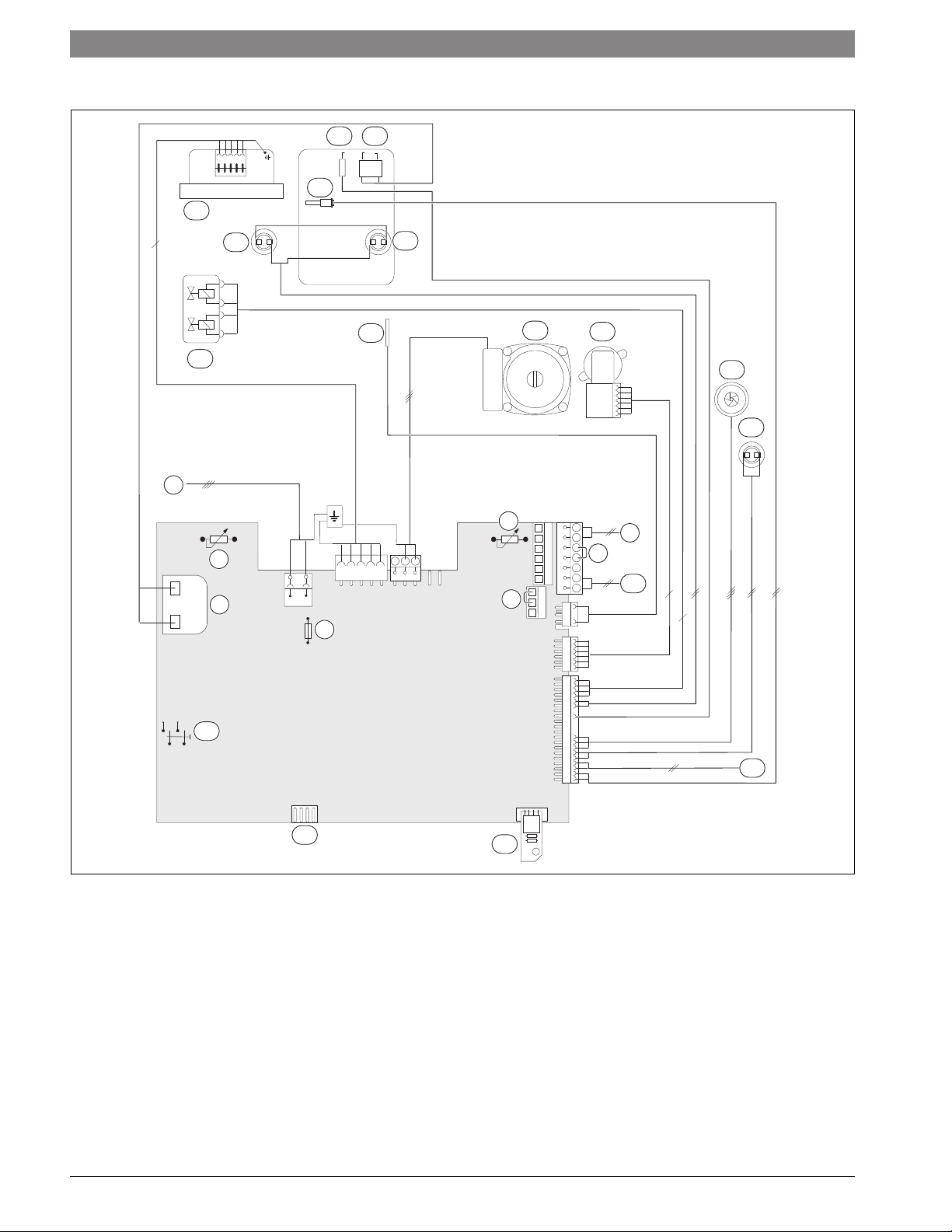
3.8 Electrical wiring
14
6
15
16
17
18
19
3
13
12
2
1
20
21
22
23
24
5
LS NS
L
N
6
B
B
4
2
F
9
A
8
7
8
7
9
6
4
4
25
11
Fig. 5 Electrical wiring
Key to Fig. 5:
[1] Ignition transformer
[2] Boiler high limit dial
[3] 120 VAC connection
[4] Fuse T 6.3 A (120 VAC)
[5] DHW thermostat
[6] External safety high limit or low water cut off (LWCO)
[7] BUS connection, e.g. heating control
[8] Room thermostat – dry contact
[9] Outdoor temperature sensor
[10] Code plug
[11] Diagnostic interface
[12] ON/OFF power switch
[13] Gas valve
10
6 720 641 933-24.3O
[14] Fan
[15] Flue gas temperature limiter
[16] Supply temperature sensor
[17] Flame rod electrode
[18] Ignition electrode
[19] Boiler block temperature limiter
[20] DHW temperature sensor
[21] Boiler circulator
[22] 3-way valve (Space heating/DHW heating)
[23] Flow turbine complete
[24] Additional supply temperature limiter
[25] External system supply temperature sensor
Greenstar combi 100 p / 151 p6720872361 (2017/04)
Product Description | 11
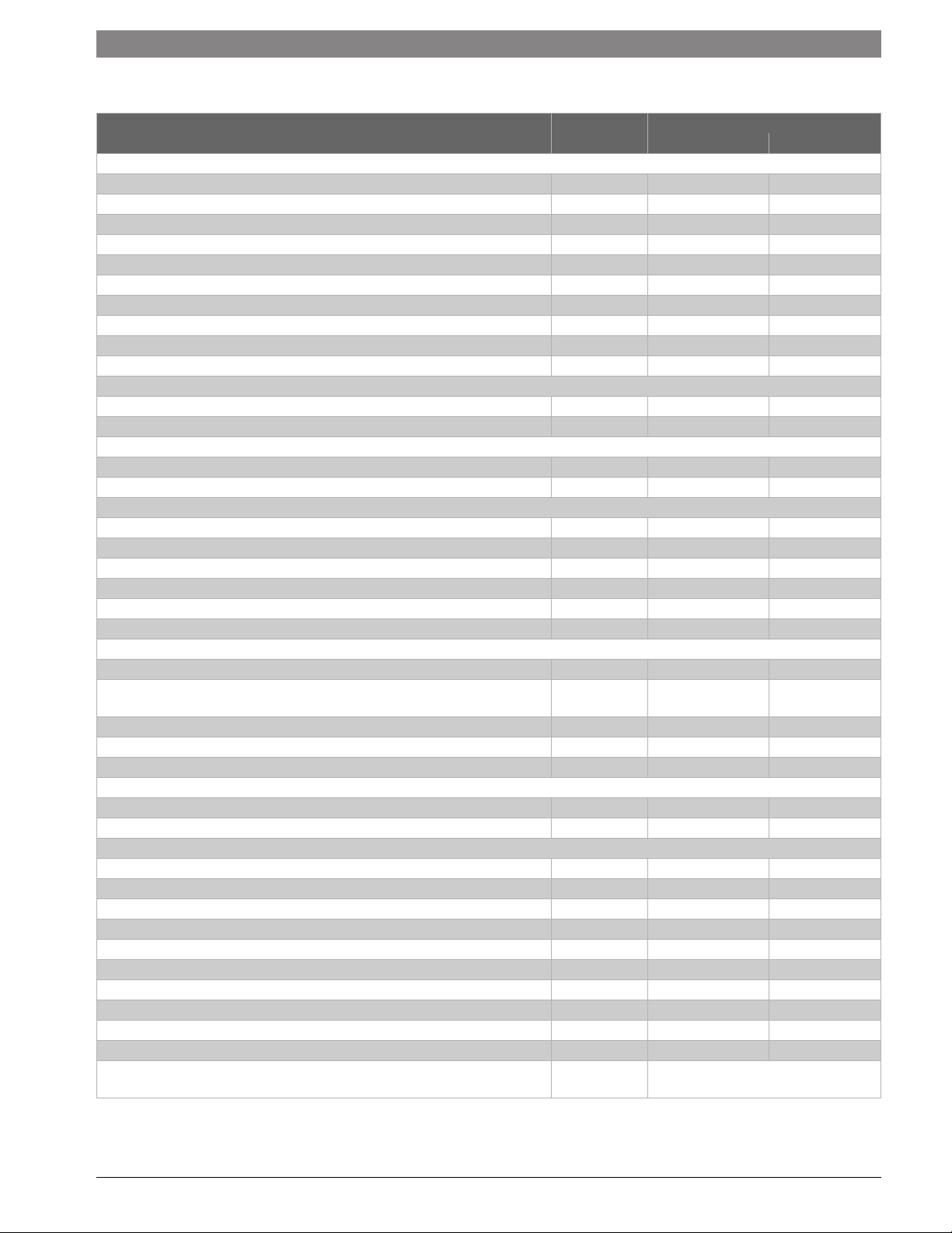
3.9 Technical data
Greenstar combi 100 p, ZWB28-3A...
Unit NG LPG (propane)
Input/Output
Max. input rate 180/79 °F (82/26 °C) BTU/hr (kW) 100,000 (29.3) 98,600 (28.9)
Max. output rate 104/86 °F (40/30 °C) BTU/hr (kW) 93,800 (27.5) 93,800 (27.5)
Max. output rate 122/86 °F (50/30 °C) BTU/hr (kW) 93,100 (27.3) 93,100 (27.3)
Max. output rate 176/140 °F (80/60 °C) BTU/hr (kW) 89,400 (26.2) 89,400 (26.2)
Output rate domestic hot water (DHW), 113 °F (45 °C) BTU/hr (kW) 93,600 (27.4) 93,600 (27.4)
Output rate domestic hot water (DHW), 140 °F (60 °C) BTU/hr (kW) 91,400 (26.8) 91,400 (26.8)
Min. input rate 180/79 °F (82/26 °C) BTU/hr (kW) 24,600 (7.2) 40,100 (11.7)
Min. output rate 104/86 °F (40/30 °C) BTU/hr (kW) 23,900 (7.0) 39,900 (11.7)
Min. output rate 122/86 °F (50/30 °C) BTU/hr (kW) 23,900 (7.0) 39,600 (11.6)
Min. output rate 176/140 °F (80/60 °C) BTU/hr (kW) 21,800 (6.4) 36,200 (10.6)
Gas connection value
Natural Gas – H
Liquid Propane Gas – H
Permissible inlet gas pressure
NG in. W.C. (mbar) 3.5-10.5" (8.7-26.1) –
LPG (propane) in. W.C. (mbar) – 8-13" (19.9-32.3)
DHW
Max. DHW flow rate gpm (l/min) 2.64 (10) 2.64 (10)
Nominal DHW flow rate (at 140 °F (60 °C) outlet temperature) gpm (l/min) 2.03 (7.7) 2.03 (7.7)
Outlet temperature °F ( °C) 104 - 140 (40 - 60) 104 - 140 (40 - 60)
Max. cold water inlet temperature °F ( °C) 140 (60) 140 (60)
Max. approved DHW pressure psi (bar) 150 (10.3) 150 (10.3)
Minimum water pressure psi (bar) 4.35 (0.3) 4.35 (0.3)
Flue gas
Flue gas mass flow at maximum/minimum nominal output g/s 12.0/3.2 11.7/4.9
Flue gas temperature 176/140 °F (80/60 °C) at maximum/minimum nominal heat
input
Flue gas temperature 104/86 °F (40/30 °C) at maximum/minimum nominal heat input °F ( °C) 117/90 (47/32) 117/90 (47/32)
CO
at max. nominal output % 9.4 11.0
2
CO2 at minimum nominal output % 8.6 10.4
Condensate
Max. condensate quantity (tR = 86 °F (30 °C)) gph (l/h) 0.6 (2.3) 0.6 (2.3)
pH level, approx. 4.8 4.8
General
Voltage VAC 120 120
Frequency Hz 60 60
Max. power consumption (central heating mode) W 205 205
Max. power consumption (Stand-by) W < 6 < 6
Sound pressure level dB(A) 39 39
Max. supply temperature °F ( °C) 187 (86) 187 (86)
Max. permissible operating pressure (P
Permissible ambient temperature °F ( °C) 32 - 122 (0 - 50) 32 - 122 (0 - 50)
Nominal water capacity (heating) gal (l) 0.925 (3.5) 0.925 (3.5)
Weight (without packaging) lbs. (kg) 110.2 (50) 110.2 (50)
Dimensions, W x H x D inch
Table 3 Technical data ZWB28-3A...
= 1,010 BTU/ft3 (37.3MJ/m3) BTU/ft3 (MJ/m3) 99 (2.8) –
s
= 2,500 BTU/ft3 (93.1MJ/m3) BTU/ft3 (MJ/m3) – 39 (1.1)
D-S
°F ( °C) 147/133 (64/56) 147/133 (64/56)
) heating psi (bar) 30 (2.07) 30 (2.07)
MS
17-21/64" × 33-15/32" × 13-57/64"
(mm)
(440 × 850 × 353)
6720872361 (2017/04)Greenstar combi 100 p / 151 p
12 | Product Description
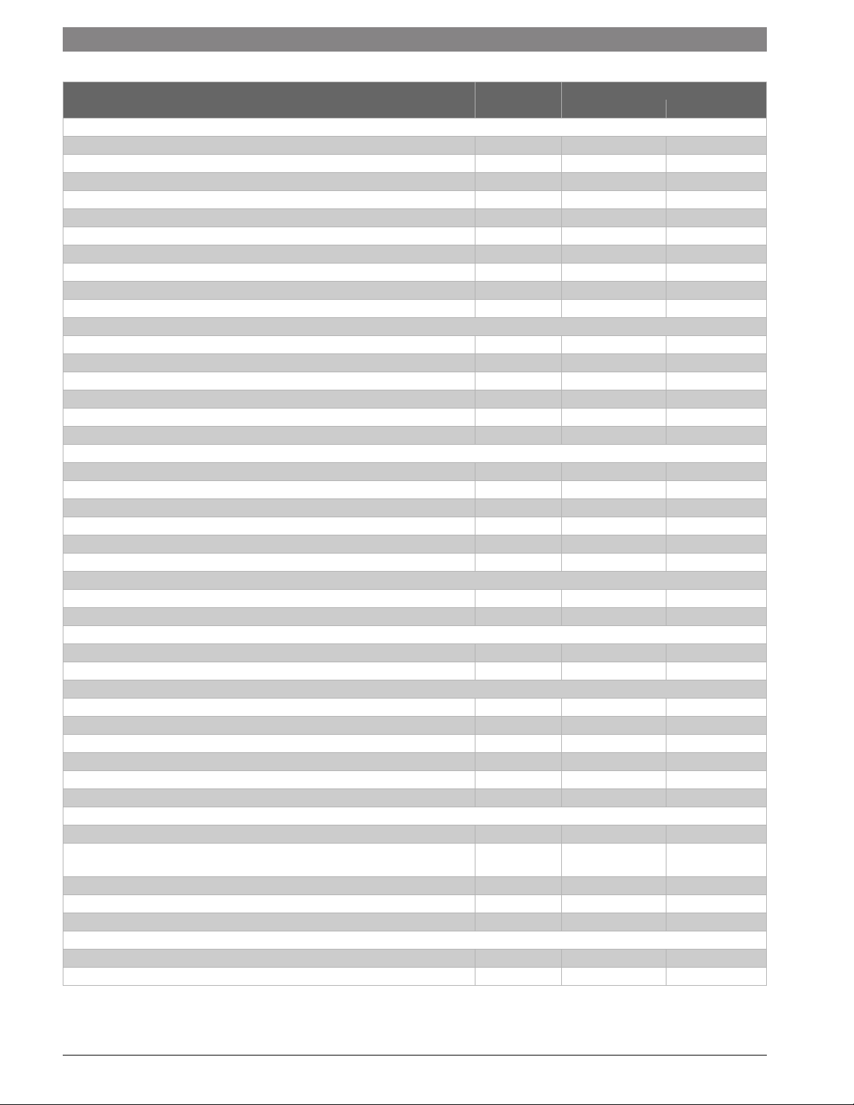
Greenstar combi 151 p, ZWB42-3A...
Unit NG LPG (propane)
Input/Output at elevation 0 - 2000 feet (0 - 610 m) above sea level
Max. input rate 180/79 °F (82/26 °C) BTU/hr (kW) 151.600 (44.4) 148.300 (43.5)
Max. output rate 104/86 °F (40/30 °C) BTU/hr (kW) 137.500 (40.3) 137.500 (40.3)
Max. output rate 122/86 °F (50/30 °C) BTU/hr (kW) 137.500 (40.3) 137.500 (40.3)
Max. output rate 176/140 °F (80/60 °C) BTU/hr (kW) 134.400 (39.4) 134.400 (39.4)
Output rate domestic hot water (DHW), 113 °F (45 °C) BTU/hr (kW) 137.500 (40.3) 137.500 (40.3)
Output rate domestic hot water (DHW), 140 °F (60 °C) BTU/hr (kW) 135.800 (39.8) 135.800 (39.8)
Min. input rate 180/79 °F (82/26 °C) BTU/hr (kW) 36.000 (10.5) 46.400 (13.6)
Min. output rate 104/86 °F (40/30 °C) BTU/hr (kW) 35.500 (10.4) 46.400 (13.6)
Min. output rate 122/86 °F (50/30 °C) BTU/hr (kW) 35.100 (10.3) 46.100 (13.5)
Min. output rate 176/140 °F (80/60 °C) BTU/hr (kW) 31.700 (9.3) 42.000 (12.3)
Input/Output at elevation 2000 - 4500 feet (611 - 1372 m) above sea level
Max. input rate 180/79 °F (82/26 °C) BTU/hr (kW) 136.440 (40.0) 139.402 (40.9)
Max. output rate 104/86 °F (40/30 °C) BTU/hr (kW) 123.750 (36.3) 129.250 (37.9)
Max. output rate 122/86 °F (50/30 °C) BTU/hr (kW) 123.750 (36.3) 129.250 (37.9)
Max. output rate 176/140 °F (80/60 °C) BTU/hr (kW) 120.960 (35.5) 126.336 (37.0)
Output rate domestic hot water (DHW), 113 °F (45 °C) BTU/hr (kW) 123.750 (36.3) 129.250 (37.9)
Output rate domestic hot water (DHW), 140 °F (60 °C) BTU/hr (kW) 122.220 (35.8) 127.652 (37.4)
Input/Output at elevation 4500 - 7000 feet (1373 - 2134 m) above sea level
Max. input rate 180/79 °F (82/26 °C) BTU/hr (kW) 125.828 (36.9) 129.021 (37.8)
Max. output rate 104/86 °F (40/30 °C) BTU/hr (kW) 114.125 (33.5) 119.625 (35.1)
Max. output rate 122/86 °F (50/30 °C) BTU/hr (kW) 114.125 (33.5) 119.625 (35.1)
Max. output rate 176/140 °F (80/60 °C) BTU/hr (kW) 111.552 (32.7) 116.928 (34.3)
Output rate domestic hot water (DHW), 113 °F (45 °C) BTU/hr (kW) 114.125 (33.5) 119.625 (35.1)
Output rate domestic hot water (DHW), 140 °F (60 °C) BTU/hr (kW) 112.714 (33.0) 118.146 (34.6)
Gas connection value
Natural gas – H
LPG propane – H
= 1.010 BTU/ft3 (37.3MJ/m3) BTU/ft3 (MJ/m3) 149 (4.2) –
s
= 2.500 BTU/ft3 (93.1MJ/m3) BTU/ft3 (MJ/m3) – 59 (1.7)
D-S
Permissible inlet gas pressure
NG " W.C. (mbar) 3.5-10.5 (8.7-26.1) –
LPG (propane) " W.C. (mbar) – 8-13 (19.9-32.3)
DHW
Max. DHW flow rate gpm (l/min) 3,963 (15) 3,963 (15)
Nominal DHW flow rate (at 140 °F (60 °C) outlet temperature) gpm (l/min) 3.61 (11.4) 3.61 (11.4)
Outlet temperature °F ( °C) 104 - 140 (40 - 60) 104 - 140 (40 - 60)
Max. cold water inlet temperature °F ( °C) 140 (60) 140 (60)
Max. approved DHW pressure psi (bar) 150 (10.3) 150 (10.3)
Minimum water pressure psi (bar) 4.35 (0.3) 4.35 (0.3)
Flue gas
Flue gas mass flow at maximum/minimum nominal output g/s 18.0/4.5 17.5/5.6
Flue gas temperature 176/140 °F (80/60 °C) at maximum/minimum nominal heat
°F ( °C) 171/135 (77/57) 171/135 (77/57)
input
Flue gas temperature 104/86 °F (40/30 °C) at maximum/minimum nominal heat input °F ( °C) 133/91 (56/33) 133/91 (56/33)
CO
at max. nominal output % 9.4 11.0
2
CO2 at minimum nominal output % 8.6 10.4
Condensate
Max. condensate quantity (tR = 86 °F (30 °C)) gph (l/h) 0.9 (3.5) 0.9 (3.5)
pH level, approx. – 4.8 4.8
Greenstar combi 100 p / 151 p6720872361 (2017/04)
Regulations | 13
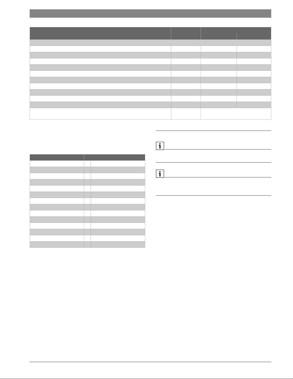
Greenstar combi 151 p, ZWB42-3A...
Unit NG LPG (propane)
General
Voltage VAC 120 120
Frequency Hz 60 60
Max. power consumption (central heating mode) W 205 205
Max. power consumption (Stand-by) W < 6 < 6
Sound pressure level dB(A) 45 45
Max. supply temperature °F ( °C) 187 (86) 187 (86)
Max. permissible operating pressure (P
Permissible ambient temperature °F ( °C) 32 - 122 (0 - 50) 32 - 122 (0 - 50)
Nominal water capacity (heating) gal (l) 0.925 (3.5) 0.925 (3.5)
Weight (without packaging) lbs. (kg) 110.2 (48) 110.2 (48)
Dimensions, W x H x D inch
Table 4 Technical data ZWB42-3A...
) heating psi (bar) 30 (2.07) 30 (2.07)
MS
17-21/64" × 33-15/32" × 13-57/64"
(mm)
(440 × 850 × 353)
3.10 Condensate composition
The condensate volume and ingredients may change with regionally and
seasonally varying gas quality and air quality. Typically the following
ingredients and concentrations can be expected:
Substance Value in ppm (mg/l)
Ammonium 1.2
Lead 0.01
Cadmium 0.001
Chrome 0.005
Halogenated hydrocarbons 0.002
Hydrocarbons 0.015
Copper 0.028
Nickel 0.1
Mercury 0.0001
Sulfate 1
Zinc 0.015
Tin 0.01
Vanadium 0.001
pH-value 4.8
Table 5 Typical condensate composition
4 Regulations
Observe all rules, regulations, standards and guidelines applicable to the
installation and operation of this appliance in your country.
Valves external to the boiler must be fitted with T-handles and
condensate piping must be installed in accordance with the State
Plumbing Code.
4.1 Compliance with standards and regulations
The installation must conform to the requirements of the authority
having jurisdiction or, in the absence of such requirements, to the latest
edition of the National Fuel Gas Code, ANSI Z223.1./NFPA 54. In
Canada, installation must be in accordance with the requirements of
CAN/CSA B149.1, Natural Gas and Propane Installation Code.
This wall-mounted condensing gas boiler complies in its design and
mode of operation with the American National Standard ANSI Z21.13/
CSA4.9, latest edition for Gas-Fired Low-Pressure Steam and Hot Water
Boilers.
Other confirmed approvals and certifications are indicated by labels on
the boiler.
If so advised by the responsible agency, the installation must satisfy the
requirements of the standard for Controls and Safety Devices for.
Automatically Fired Boilers, ANSI/ASME CSD-1.
Install CO detectors per local regulations. Wall-mounted gas condensing
boilers require yearly maintenance ( Chapter 14, page 48).
6720872361 (2017/04)Greenstar combi 100 p / 151 p

14 | Regulations
4.2 Operating limits of the boiler
The heat exchanger has been designed and certified in accordance with
the ASME Boiler and Pressure Vessel Code, Section IV.
Maximum boiler temperature 187 °F (86 °C)
Maximum operating pressure 30 psi (2.07 bar)
Table 6 Operating limits
The hot water distribution system must comply with all applicable codes
and regulations. When replacing an existing boiler, it is important to
check the condition of the entire hot water distribution system to ensure
safe operation.
Common practice calls for inspecting an existing system in its entirety
and bringing it up to code. All pipework should be properly cleaned and
flushed.
4.3 Additional regulations for installations in the
Commonwealth of Massachusetts
(a) For all side wall side horizontally vented gas fueled equipment
installed in every dwelling, building or structure used in whole or in part
for residential purposes, including those owned or operated by the
Commonwealth and where the side wall exhaust vent termination is less
than seven (7) feet [2150 mm] above finished grade in the area of the
venting, including but not limited to decks and porches, the following
requirements shall be satisfied:
• INSTALLATION OF CARBON MONOXIDE DETECTORS. At the time of
installation of the side wall horizontal vented gas-fueled equipment,
the installing plumber or gas fitter shall ensure that a hard-wired
carbon monoxide detector with an alarm and uninterruptible power
supply is installed on the floor level where the gas equipment is to be
installed. In addition, the installing plumber or gas fitter shall ensure
that a battery-operated or hard-wired carbon monoxide detector
with an alarm is installed on each additional level of the dwelling,
building or structure served by the side wall horizontal vented gasfueled equipment. It shall be the responsibility of the property owner
to secure the services of qualified licensed professionals for the
installation of hard-wired carbon monoxide detectors.
– In the event that the side wall horizontally vented gas-fueled
equipment is installed in a crawl space or an attic, the hard-wired
carbon monoxide detector with alarm and uninterruptible power
supply may be installed on the next adjacent floor level.
– In the event that the requirements of this subsection can not be
met at the time of completion of installation, the owner shall have
a period of thirty (30) days to comply with the above
requirements; provided, however, that during said thirty (30) day
period, a battery-operated carbon monoxide detector with an
alarm shall be installed.
• APPROVED CARBON MONOXIDE DETECTORS. Each carbon
monoxide detector as required in accordance with the above
provisions shall comply with NPA 720 and be ANSI/UL 2034 listed
and IAS certified.
• SIGNAGE. A metal or plastic identification plate shall be permanently
mounted to the exterior of the building at a minimum height of eight
(8) feet above grade directly in line with the exhaust vent terminal for
the horizontally vented gas0fueled heating appliance or equipment.
The sign shall read, in print size no less than one-half (½) inch in size,
“GAS VENT DIRECTLY BELOW. DO NOT BLOCK.”
• CHECK. The state or local gas inspector of the side wall horizontally
vented gas-fueled equipment shall not approve the installation
unless, upon inspections, the inspector observes carbon monoxide
detectors and signage installed in accordance with the provisions of
248 CRM 5.08(2)(a) 1 through 4.
(b) EXEMPTIONS: The following equipment is exempt from 248 CRM
5.08(2)(a) 1 through 4:
• The equipment listed in Section 10 entitled “Equipment Not
Required To Be Vented” in the most current edition of NFPA 54 as
adopted by the board; and
• Approved side wall horizontally vented gas-fueled equipment
installed in a room or structure separate from the dwelling, building
or structure used in whole or in part for residential purposes.
(c) MANUFACTURER'S REQUIREMENTS - GAS EQUIPMENT VENTING
SYSTEM REQUIRED. When the manufacturer of Product Approved side
wall horizontally mounted gas-fueled equipment provides a venting
system design or venting system components with the equipment, the
instructions provided by the manufacturer for the installation of the
equipment and venting shall include:
• Detailed instructions for the installation of the venting system or the
venting system components; and
• a comprehensive parts list for the design and the components of the
venting system.
(d) MANUFACTURER'S REQUIREMENTS – NO VENTING SYSTEM FOR
GAS EQUIPMENT INCLUDED IN THE SCOPE OF DELIVERY. When the
manufacturer of Product Approved side wall horizontally vented gasfueled equipment does not provide the parts for the venting of flue
gases, but identifies “special venting systems”, the following
requirements shall be satisfied by the manufacturer:
• The referenced “special venting systems” shall be included with the
appliance or equipment installation instructions.
• The “special venting systems” shall be Product Approved by the
Board, and the instructions for that system shall include a parts list
and detailed installation instructions.
(e) A copy of all instructions for all Product Approved side wall
horizontally vented gas-fueled equipment, all venting instructions, all
parts lists for venting instructions, and/or venting design instructions
shall remain with the appliance or equipment at the completion of the
installation.
Greenstar combi 100 p / 151 p6720872361 (2017/04)
5 Examples of Installations
H2O
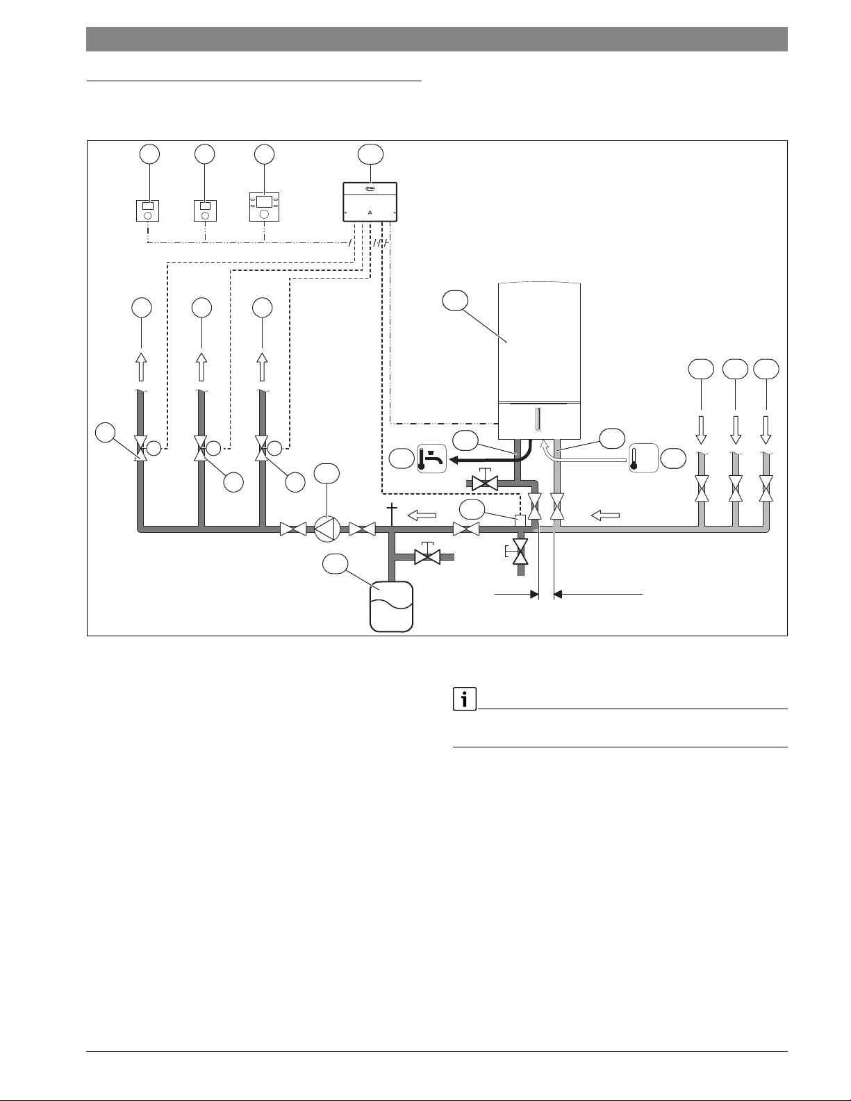
5.1 Multiple zones using zone valves with DHW
Examples of Installations | 15
3 6
2
5
8
119
1112
1918 20
1
M M M
1113
14
4 7
10
15
ϑ
17
1116
21
Fig. 6 Piping
[1] Motorized valve heating zone 3
[2] To heating zone 3
[3] Bosch room temperature controller heating zone 3 (CRC100)
[4] Motorized valve heating zone 2
[5] To heating zone 2
[6] Bosch room temperature controller heating zone 2(CRC100)
[7] Motorized valve heating zone 1
[8] To heating zone 1
[9] Bosch controller heating zone 1 and DHW (CRC200)
[10] System pump
[11] Comfort Zone Module CZM100
[12] Gas condensing boiler
[13] Boiler primary line - supply pipe 1"
[14] DHW
[15] External system supply temperature sensor for system
supplypipe (to be installed in closest vicinity withboiler supply
Tee)
[16] Cold water
[17] Boiler primary line - return pipe 1"
[18] From heating zone 1
[19] From heating zone 2
[20] From heating zone 3
[21] Expansion vessel (accessory)
X
0010011805-002
X 4 × pipe diameters on boiler primary side (here 4 × 1")
For all accessories not included in the package please refer to the Bosch
Product Catalog.
6720872361 (2017/04)Greenstar combi 100 p / 151 p
16 | Examples of Installations
0
1
2
3
4
5
6
1234
CZM100
VZ1
T0
1212
34 12
≤ 24 V
VZ2
3412
VZ3
24VAC
3 412
CRC100
HC3
CRC100
HC2
CRC200
HC1
120/230 V AC
120/
230VAC
NL
120 V AC
3
NL
4
PZ2 PZ3PZ1
NLNL
5
M
2
LS NS
L
N
≤ 24 V
BUSBUS
1 2
12
BUS BUS
1212
12
24 V AC
120 V AC
24 V AC
9
MM
8
76
NZ
LZ
L
N
B
B
4
2
F
9
A
8
7
10
11
12
1
F
V
13
0010011806-001
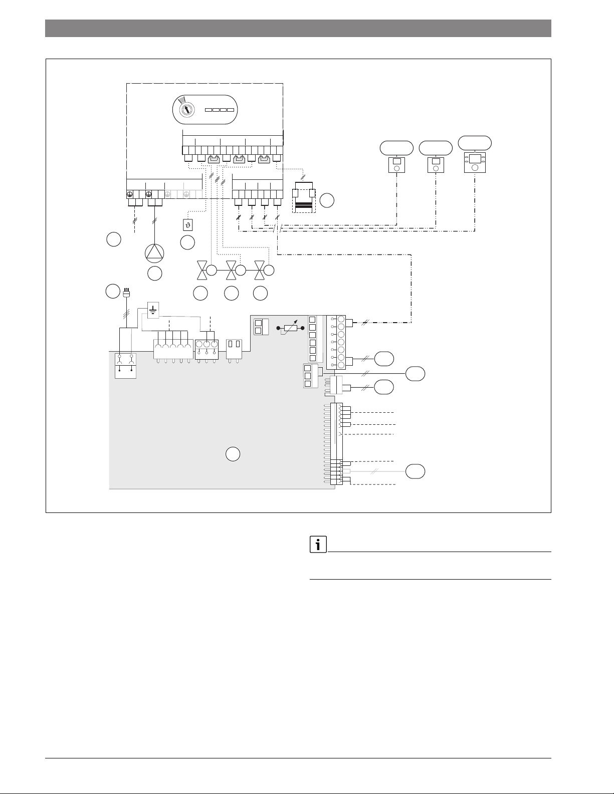
Fig. 7 Wiring
[1] PCB in wall-mounted gas condensing boiler
[2] 120 V AC mains power (white plug) ( Chapter 7.3, page 34)
[3] 120 V AC, 60 Hz
[4] System pump
[5] External system supply temperature sensor for system supply
pipe
[6] Motorized valve heating zone 1
[7] Motorized valve heating zone 2
[8] Motorized valve heating zone 3
[9] 24 V AC transformer
[10] Outdoor temperature sensor
[11] LWCO (Low Water Cut Off, 24V AC Transformer required)
[12] DHW temperature sensor (inside gas condensing boiler)
[13] Optionally connect external system supply temperature sensor
for system supply pipe here (with white plug)
For all accessories not included in the package please refer to the Bosch
Product Catalog.
Greenstar combi 100 p / 151 p6720872361 (2017/04)
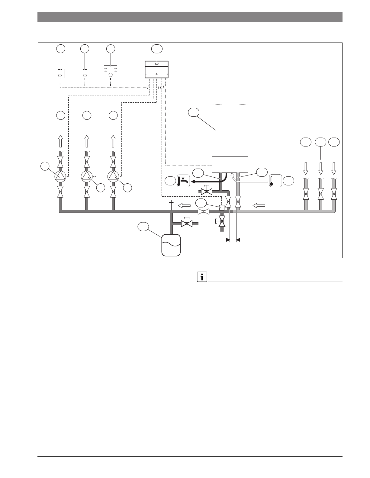
5.2 Multiple zones using circulators with DHW
H2O
Examples of Installations | 17
1
3 6
2
5
8
4 7
109
1111
19
1817
16
1115
13
1112
14
ϑ
20
Fig. 8 Piping
[1] Pump heating zone 3
[2] To heating zone 3
[3] Bosch room temperature controller heating zone 3 (CRC100)
[4] Pump heating zone 2
[5] To heating zone 2
[6] Bosch room temperature controller heating zone 2(CRC100)
[7] Pump heating zone 1
[8] To heating zone 1
[9] Bosch controller heating zone 1 and DHW (CRC200)
[10] Comfort Zone Module CZM100
[11] Gas condensing boiler
[12] Boiler primary line - supply pipe 1"
[13] DHW
[14] External system supply temperature sensor for system supply
pipe (to be installed in closest vicinity with boiler supply Tee)
[15] Cold water
[16] Boiler primary line - return pipe 1"
[17] From heating zone 1
[18] From heating zone 2
[19] From heating zone 3
[20] Expansion vessel (accessory)
X 4 × pipe diameters on boiler primary side (here 4 × 1")
X
0010011808-002
For all accessories not included in the package please refer to the Bosch
Product Catalog.
6720872361 (2017/04)Greenstar combi 100 p / 151 p
18 | Examples of Installations
0
1
2
3
4
5
6
1234
CZM100
T0
12
12 3412
VZ1
≤ 24 V
≤ 24 V
VZ234VZ3
24VAC
12
3 412
CRC100
HC3
CRC100
HC2
CRC200
HC1
120/230 V AC
120/
230VAC
NL
120 V AC
3
PZ2 PZ3PZ1
NNLNLL
7
4
5
6
1 2
≤ 24 V
BUSBUS
12
BUS BUS
1212
2
NZ
LZ
N
L
LS NS
L
N
B
B
4
2
F
9
A
8
7
8
9
10
1
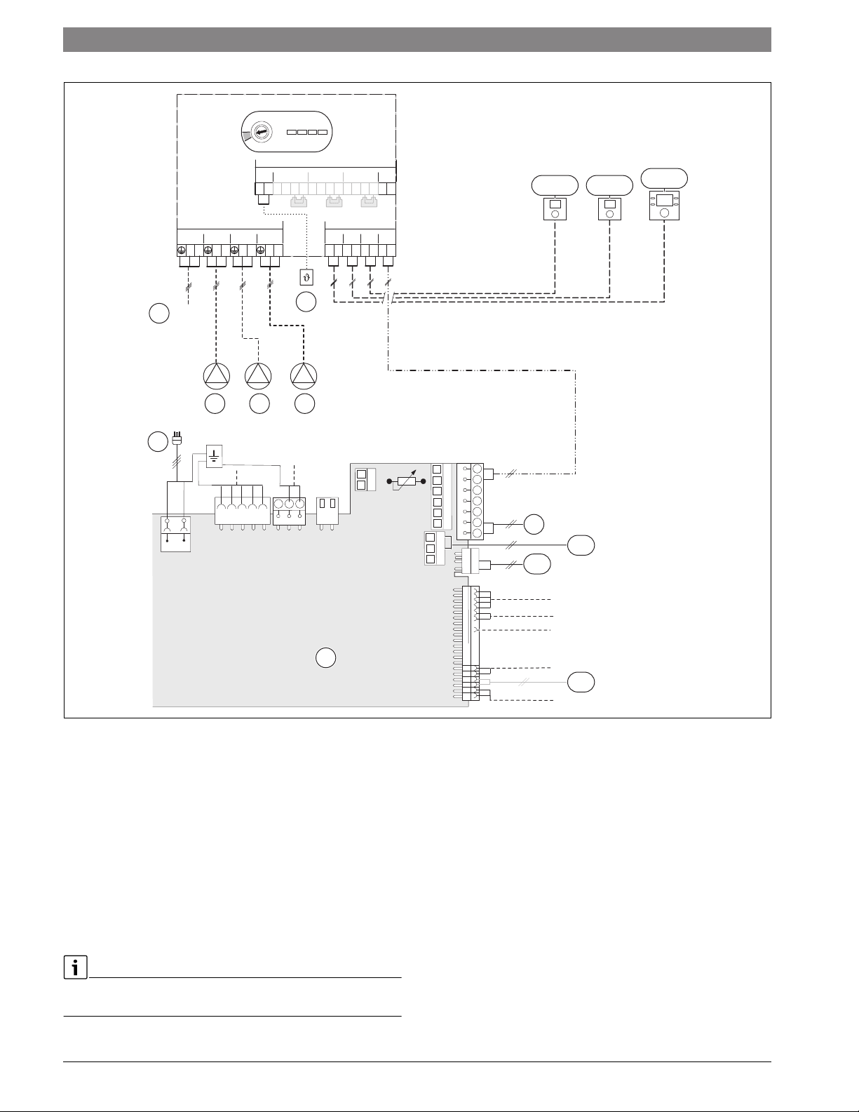
Fig. 9 Wiring
[1] PCB in wall-mounted gas condensing boiler
[2] 120 V AC mains power (white plug) ( Chapter 7.3, page 34)
[3] 120 V AC, 60 Hz
[4] Pump heating zone 1
[5] Pump heating zone 2
[6] Pump heating zone 3
[7] External system supply temperature sensor for system supply
pipe
[8] Outdoor temperature sensor
[9] LWCO (Low Water Cut Off, 24V AC Transformer required)
[10] DHW temperature sensor (inside gas condensing boiler)
[11] Optionally connect external system supply temperature sensor
for system supply pipe here (with white plug)
For all accessories not included in the package please refer to the Bosch
Product Catalog.
F
V
11
0010011809-002
Greenstar combi 100 p / 151 p6720872361 (2017/04)
6 Notes on installation and operation
DANGER:
Explosion!
▶ Close the gas cock prior to working on the gas train.
▶ Check for gas leaks after carrying out work on the gas train.
Installation, power connection, connection on the gas and flue gas side
and commissioning must only be carried out by a contractor certified for
such work by the state or local jurisdiction or the local gas or power
utility.
Notes on installation and operation | 19
Recirculation pump/DHW recirculation lines
A recirculation pump can be installed. Control and electrical connection
are not possible via the appliance's electronics. Additional accessories
are required for this.
▶ Connect the DHW circulation line at the cold water inlet as close as
possible to the hydraulics connection plate.
Total length DHW/recirculation
line
33 ft (10 m) 0.66 gpm (2.5 l/min)
33 - 66 ft (10 - 20 m) 0.92 gpm (3.5 l/min)
66 - 98 ft (20 - 30 m) 1.32 gpm (5 l/min)
Table 7 Recommended flow rates
Flow rate
6.1 Notes on installation and operation
When installing and operating the heating system observe the following:
• The elevation of the installation location above sea level must be
taken into account ( Chapter 11.2).
• Follow all local building regulations regarding the installation
conditions on site.
• The local building regulations regarding air supply and venting
systems and the chimney flue connection.
• Electrical code requirements for connection to the electrical power
supply.
• The technical regulations of the gas company regarding the
connection of the gas burner to the local gas main.
• The regulations and standards relating to the DHW heating system.
6.1.1 Important notes
Fill and make-up water for the heating system
Unsuitable fill and make-up water can result in the heating system scaling
up or failing prematurely.
Recommended steps for commissioning a new or retrofit boiler
installation
▶ Flush the system with clean water.
▶ Isolate the boiler, fill the system with fresh water and a boiler cleaner,
run for 30 minutes to 1 hour. Under no circumstances may boiler
cleaner be pumped through the boiler.
▶ Thoroughly flush the system with fresh water. Ensure all zones and
loops are flushed.
▶ Empty out sediment traps.
▶ Systems containing antifreeze not approved by Bosch, must be
completely flushed to ensure no old fluid remains.
▶ Fill the system with fresh water and the proper amount of inhibitor.
▶ Verify the pH is within the proper range.
▶ Add additional inhibitor if pH is not within the proper range.
▶ Check pH annually.
▶ If using antifreeze, fill with approved antifreeze and fresh water.
▶ Always follow the cleaner, antifreeze, or additive manufacturer’s
instructions.
▶ Do not mix different manufacturer’s products
▶ Follow manufacturer’s data to determine the anti-freeze ratio for the
desired freeze protection temperature.
You can display the flow rate through the heat exchanger with the service
function 6.d current flow through the turbine ( page 43).
Open vented heating systems
▶ Convert open vented heating systems into closed systems.
Gravity heating systems
▶ Connect the appliance to the existing piping system via a low-loss
header with a sludge separator.
Galvanized radiators or pipes.
To prevent gas formation:
▶ Do not use galvanized radiators or pipes.
Plastic pipework
If using plastic pipework for the heating system (eg.underfloor/radiant
heating), the type of pipe that should be used must be oxygen tight.
Use of a room temperature controller
▶ Do not install thermostatic valves on radiators in the primary room.
Primary-secondary piping or a low loss header
In the case of radiant floor heating, panel radiators, systems with several
heating zones or 3/4" baseboard heating (70 ft (21 m), temperature
difference 20 °F (11 °C), flow rate 4.0 gpm (15.1 L/min) plus the
required supply and return pipes), hydraulic separation of the system is
required, e. g. by means of a low-loss header.
Anti-freeze
NOTICE:
Insufficient antifreeze can accelerate corrosion.
▶ Follow manufacturer's instructions on antifreeze concentration.
▶ Frost protection level has to be checked annually during the regular
scheduled maintenance of the condensing boiler.
NOTICE:
System damage!
▶ It is the installer's responsibility to ensure that the heating system is
compatible with the boiler type and size installed.
▶ pH-value of the heating water to be kept between 7 and 8.5.
6720872361 (2017/04)Greenstar combi 100 p / 151 p
20 | Notes on installation and operation
The following anti-freeze fluids and concentrations have been approved:
Chemical Name Concentration
Nalco (Varidos) FSK 22 - 55 %
Fernox Alphi 11 Observe manufacturer's
instructions
Intercool NFP-50 AA 0 - 39 %
Antifrogen N Observe manufacturer's
instructions
NoBurst AL 0 - 55 %
Table 8 Anti-freeze
Corrosion inhibitors
The following anti-corrosion agents are approved:
Chemical Name Concentration
Fernox F1 Observe manufacturer's
instructions
Nalco 77381 1 - 2 %
Sentinel X 100 1.1 %
Table 9 Corrosion inhibitors
▶ System fluid pH must be maintained between 7 and 8.5 to prevent
system damage.
▶ Use only untreated water to fill the system.
▶ Do not use TSP (tri-sodium phosphate).
▶ Do not use fill water treated with salt bedding type exchangers (ion
exchanger).
▶ Never introduce non-approved boiler treatment or similar additives.
▶ Only use fill water with a hardness below 7 grains.
▶ Filling with chlorinated water is acceptable if chlorine levels are
below 100 ppm.
▶ Do not use inhibitors or other additives unless listed in this
document.
▶ Consult a local water treatment specialist for recommendations if any
of the above is outside the stated ranges.
▶ When using oxygen permeable PEX, the system must be separated
from the boiler by a heat exchanger.
▶ A correctly sized and working expansion vessel must be installed.
▶ Do not exceed the maximum permissible fl ow rate through the boiler.
Excessive flow can cause erosion damage to the heat exchanger.
▶ Eliminate leaks in the system
Continually topping up the system constantly adds oxygen to the
heating water, causing corrosion damage. All system leaks must be
repaired.
Boiler sealer
This boiler is not approved for use with boiler sealer.
LPG
To protect the appliance against high pressure (ANSI/Z223.1/NFPA54
(National fuel gas code) or CAN/CSA B 149.1 (Natural Gas and Propane
installation code)):
▶ Install a pressure regulator with a safety valve.
6.1.2 Other important information
• The installation of this boiler must comply with all national and local
code and regulations.
• Only operate this boiler with the combined air/flue system
specifically designed and approved for it.
• Use only approved venting systems per the manufacturer's
instructions.
• Do not dispose of untreated boiler condensate in septic systems.
• Inspect the sewer pipes for suitability before disposing of untreated
boiler condensate in them.
• Verify with the local authority that disposing of untreated boiler
condensate into public sewer systems is permitted.
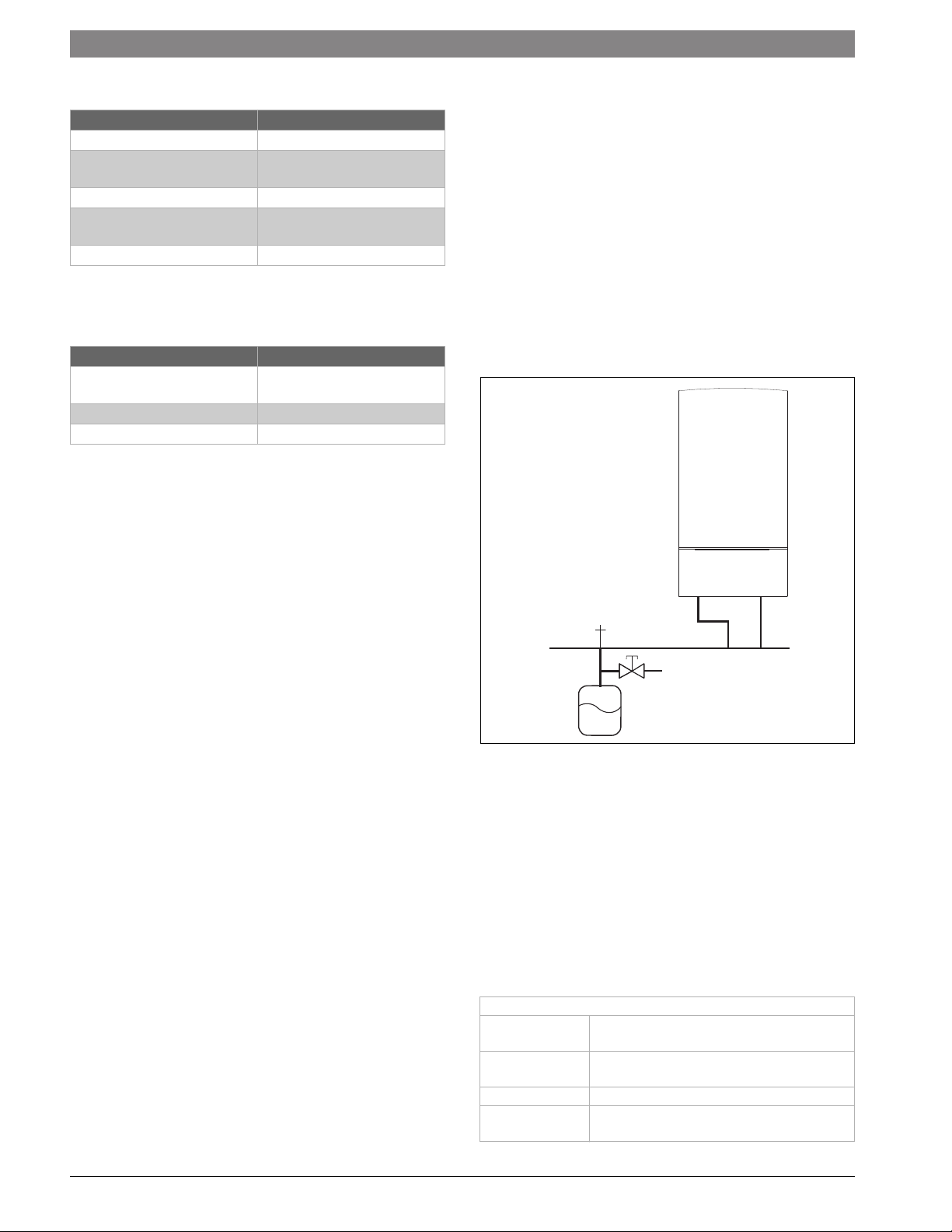
6.2 Selecting an external expansion vessel
▶ Determine the size of the expansion vessel in compliance with local
laws and regulations.
6 720 641 933-20.3O
Fig. 10 Example of installation of an external expansion vessel
6.3 Selecting the installation location
Installation location requirements
Observe the current national and local codes and regulations.
▶ Observe country-specific requirements.
▶ Observe installation instructions of the venting system accessories
and their clearances.
Combustion air
To avoid corrosion, keep the supply of combustion air free of corrosive
substances; contained in solvents, paints, adhesives, propellants and
domestic cleaning agents.
Industrial sources
Chemical cleaning Trichloroethylene, tetrachloroethylene, fluorinated
hydrocarbons
Degreasing bath Perchloroethylene, trichloroethylene,
methylchloroform
Printing shops Trichloroethylene
Hair salons Aerosol propellants, hydrocarbons containing fluorine
and chlorine (difluorodichloromethane)
Greenstar combi 100 p / 151 p6720872361 (2017/04)
 Loading...