

Bosch UEZ Operation Manual

614–30.0212.0270–01 A2 1
OPERATING
INSTRUCTIONS
UEZ – Intrusion Alarm
30.0221.9701 A2
Introduction and Notes on Security 3. . . . . . . . . . . . . . . . . .
Explanation of Display and Operating Elements 4. . . . . . .
Display/operating panel 5. . . . . . . . . . . . . . . . . . . . . . . . . . . . . .
Individual/group displays (LED) 5. . . . . . . . . . . . . . . . . . . . . . .
Message processing keys / softkeys with display 6. . . . . . . . .
Fixed function keys 7. . . . . . . . . . . . . . . . . . . . . . . . . . . . . . . . .
Cursor keys 10. . . . . . . . . . . . . . . . . . . . . . . . . . . . . . . . . . . . . . .
Key switch 10. . . . . . . . . . . . . . . . . . . . . . . . . . . . . . . . . . . . . . . .
Sealed switch 10. . . . . . . . . . . . . . . . . . . . . . . . . . . . . . . . . . . . .
Message Display/Processing
Explanation of display messages 11. . . . . . . . . . . . . . . . . . . . .
Messages with message processing keys 12. . . . . . . . . . . . .
Calling up a list of all message types 13. . . . . . . . . . . . . . . . .
Alarm Verification: see page 48
continued on next page
Message Display/Processing
Resetting the central control unit 14. . . . . . . . . . . . . . . . . . . .
Resetting detector zones/message types 15. . . . . . . . . . . .
Resetting with “General Reset” 16. . . . . . . . . . . . . . . . . . . . .
Arming the System 17. . . . . . . . . . . . . . . . . . . . . . . . . . . . . . . .
Timer–Controlled Switching
Timer–controlled activation (TCA) 18. . . . . . . . . . . . . . . . . . .
Timer–controlled deactivation 19. . . . . . . . . . . . . . . . . . . . . .
Operation Authorisation
User Code 20. . . . . . . . . . . . . . . . . . . . . . . . . . . . . . . . . . . . . .
Basic/complete/maintenance operation 21. . . . . . . . . . . . .
Table of Contents

614–30.0212.0270–01 A2 2
Table of Contents
Operating the Functions in the Main Menu
Calling up/quitting the Main Menu and Submenus 24.
Viewing the Alarm Counter 24. . . . . . . . . . . . . . . . . . . . . . .
Areas (Status Interrogation)
– Interrogation of the zone status 25. . . . . . . . . . . . . . . . . . .
– Switch block type lock lamps on/off 26. . . . . . . . . . . . . . . .
– Skip detector zones and malfunctions 26. . . . . . . . . . . . .
Internal Program
– Switch internal program on/off 27. . . . . . . . . . . . . . . . . . . .
– Edit internal program 28. . . . . . . . . . . . . . . . . . . . . . . . . . . .
Switch Visual Test on/off 29. . . . . . . . . . . . . . . . . . . . . . . . .
Timer
– Switch timer channels on/off 30. . . . . . . . . . . . . . . . . . . . . .
– Change switching times 31. . . . . . . . . . . . . . . . . . . . . . . . .
Background Memory
– View background memory 32. . . . . . . . . . . . . . . . . . . . . . .
– Going to a certain event 33. . . . . . . . . . . . . . . . . . . . . . . . .
(event number, date, latest)
– Select/search events 34. . . . . . . . . . . . . . . . . . . . . . . . . . . .
– Print events 35. . . . . . . . . . . . . . . . . . . . . . . . . . . . . . . . . . . .
– Diagnosis 36. . . . . . . . . . . . . . . . . . . . . . . . . . . . . . . . . . . . . .
Operating the Functions in the Main Menu
Changing the Operator Code 37. . . . . . . . . . . . . . . . . . . . . . .
Switching on/off
– Switch group list on/off 38. . . . . . . . . . . . . . . . . . . . . . . . . . . . .
– Switch detector zones on/off 39. . . . . . . . . . . . . . . . . . . . . . .
– Switch detectors on/off 40. . . . . . . . . . . . . . . . . . . . . . . . . . . .
– Switch tableau points on/off 41. . . . . . . . . . . . . . . . . . . . . . . .
– Switch sounders/strobes on/off 42. . . . . . . . . . . . . . . . . . . . .
Maintenance 43. . . . . . . . . . . . . . . . . . . . . . . . . . . . . . . . . . . . . .
Blocking
– Block zones 44. . . . . . . . . . . . . . . . . . . . . . . . . . . . . . . . . . . . . .
– Block detectors 45. . . . . . . . . . . . . . . . . . . . . . . . . . . . . . . . . . .
System Parameters
– Change date/time 46. . . . . . . . . . . . . . . . . . . . . . . . . . . . . . . . .
– Change PC interface 47. . . . . . . . . . . . . . . . . . . . . . . . . . . . . .
Alarm Verification 48. . . . . . . . . . . . . . . . . . . . . . . . . . . . . . . . . .

614–30.0212.0270–01 A2 3
Introduction and Notes on Security
BOSCH Telecom Service Center:
Telephone:
The UEZ must only be operated by trained personnel!
For safety reasons and to prevent unauthorised
operation, only these personnel should know the
authorisation code required to operate the system.
What information is contained in these operating instructions?
These instructions contain all the information that you require
to operate the UEZ.
What information is not contained in these operating instructions?
The operating instructions do not contain any information regarding general or special security–related knowledge.
Therefore: Ensure that you are familiar with all of the
security–related procedures and regulations of your area (for
example, alarm procedures, plans of action, alarm
organisation, etc.).
Destruction of the UEZ display screen resulting from an external source does not pose any direct risk for the user (for example, explosion, implosion, dangerous gases, etc.).
Contact the Service Department if the UEZ is damaged.
When cleaning the surface of the UEZ (especially the operating
and display unit), do not use any corrosive or abrasive cleaning
materials and do not allow any liquid to leak into the interior of
the equipment.
614–30.0212.0270–01 A2 4
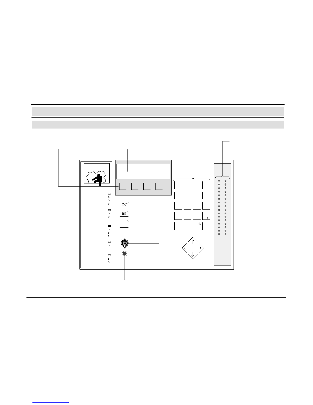
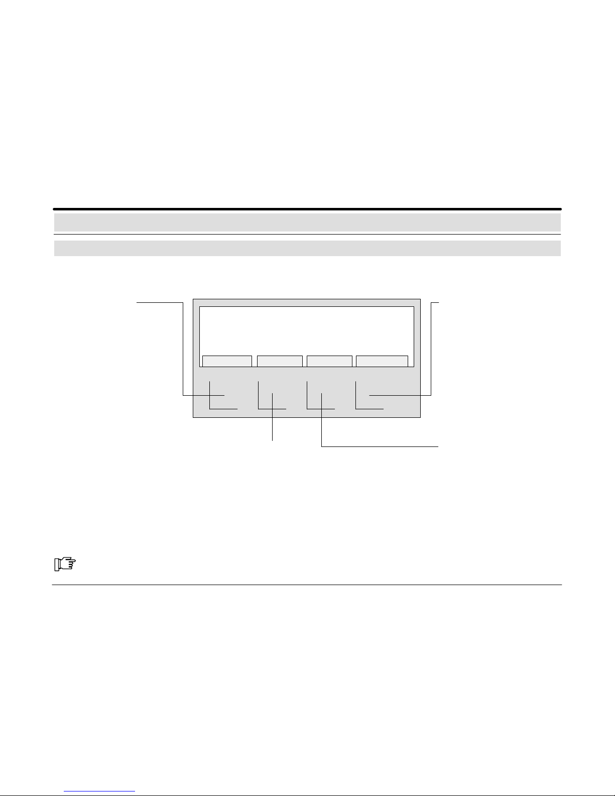
Explanation of Display and Operating Elements
Display/Operating Panel
Message processing keys/
softkeys
F
code
1
stop
102
ABC2DEF3GHI
4
JKL5MNO6PQR
reset
7
STU8VWX9YZ
enter
CE
0+1
./:
inter–
nation
help ? test
Display
panel
Key switch Cursor keys
Keys for character input
and fixed function keys
Individual/group
displays (LED)
Quit or cancel
function
Sounders/strobes off
Buzzer off
∑
Individual zone display
(LED)
red = alarm
17
18
19
20
21
22
23
24
25
26
27
28
29
30
31
32
1
2
3
4
5
6
7
8
9
10
11
12
13
14
15
16
Sealed switch for
“General reset”
Maintenance
Continue
System
Malfunction
Message
Internal alarm
External alarm
Alarm
Internal on
Code operation
Operation
Transmission unit
Control
Signal unit
Tableau
Switch Off
614–30.0212.0270–01 A2 5
Alarm (red) illuminates when an external or internal alarm, a pre–alarm, or a fault in the external alarm system
occurs. The alarm is stored and signalled by a buzzer.
External Alarm (red) illuminates if an alarm is reported to an external emergency position or if external
sounders and strobes are triggered.
Internal Alarm (red) illuminates if an internal alarm is triggered but not reported to an external emergency
position.
Message (red) illuminates if a message is issued. The message is stored and the buzzer is activated.
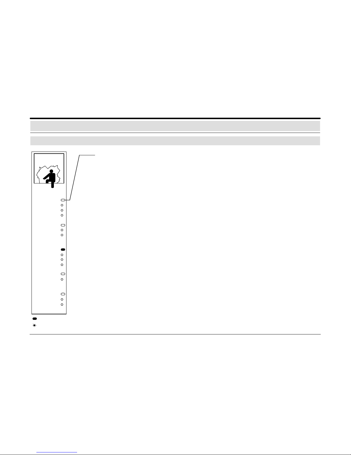
Explanation of Display and Operating Elements
Individual/group displays (LED)
Maintenance
Continue
System
Malfunction
Message
Internal Alarm
External Alarm
Alarm
Internal on
Code operation
Operation
Transmission unit
Control
Signal unit
Tableau
Switch Off
Malfunction (yellow) illuminates when any kind of malfunction occurs. The appropriate malfunction message
is usually stored (not, for example, in case of a network malfunction) and the buzzer is activated. If the
type of malfunction cannot be reset by the authorised operating personnel, contact the Service Department.
System (yellow) illuminates when a system malfunction (logic malfunction) occurs.
Continue (yellow) illuminates if a triggered or malfunctioning zone or a ring or stubline malfunction has
been removed from the surveillance system to arm a detector area. After disarming the detector area, contact the Service Department.
Operation (green) illuminates when the central control unit is ready for operation.
Code operation (yellow) flashes when the correct operator code has been entered.
Internal on (green) illuminates if one internal program has been switched on.
Maintenance (yellow) illuminates during a system maintenance.
Control (yellow) illuminates when a system function is triggered.
Transmission unit (red) illuminates if the transmission unit has been triggered. External emergency per-
sonnel (for example, police or surveillance personnel) have been alerted.
Switch Off (yellow) illuminates if detectors, zones, tableau items, or sounders/strobes are deactivated. The
indicator switches off when all devices are reactivated.
Tableau (yellow) illuminates if central or zone tableau items are deactivated. In this case, the tableau items
are not triggered.
Signal Unit (yellow) illuminates if a connected sounder/strobe is deactivated. The sounders/strobes do
not transmit any alarm in this case. The indicator switches off when all devices are reactivated.
Indicator illuminates
Indicator flashes
614–30.0212.0270–01 A2 6
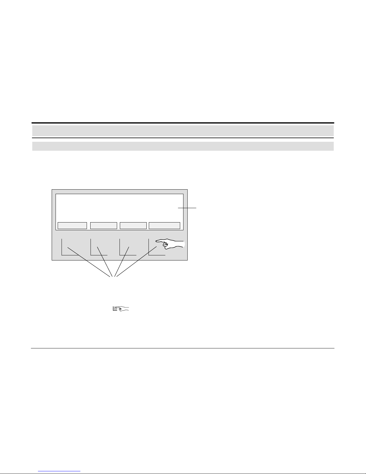
Explanation of Display and Operating Elements
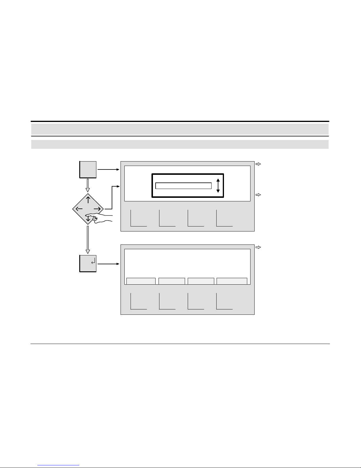
Message processing keys / softkeys with display
Message processing keys/softkeys:
Using the 4 message processing keys/softkeys, the messages/functions shown
above the keys in the display can be called up.
The text shown in the display above each key indicates the operation of each key.
Pressing the key displays further messages/functions with notes regarding
the additional operating steps.
Quiescent condition:
If the central control unit is in the quiescent condition, e.g. no messages have appeared and no functions have been called up from
the main menu, the screen saver appears in the display.
MESSAGES DETECTOR MESS.TYPE ACTIONS
Display:
In the clear text display, all existing messages, such as
intrusion, malfunction and switchoff, as well as notes regarding operation are displayed in the main menu.
1 INTRUS. INT ZONE 0035 – 16
Storage room entrance 1st floor
2 INTRUS. INT ZONE 0040 – 07
Offfice building south 1st floor
614–30.0212.0270–01 A2 7
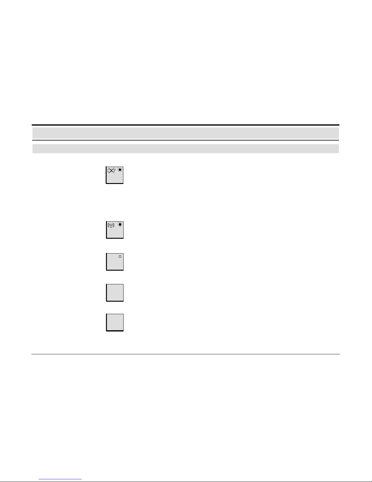
Explanation of Display and Operating Elements
Fixed function keys
Switch on/off
sounders/strobes
Switch off buzzer The indicator flashes and the buzzer sounds when the following messages occur:
– Alarm
– Message
– Malfunction
– Maintenance alarm
When this key is pressed, the buzzer is deactivated and the flashing indicator is switched
off.
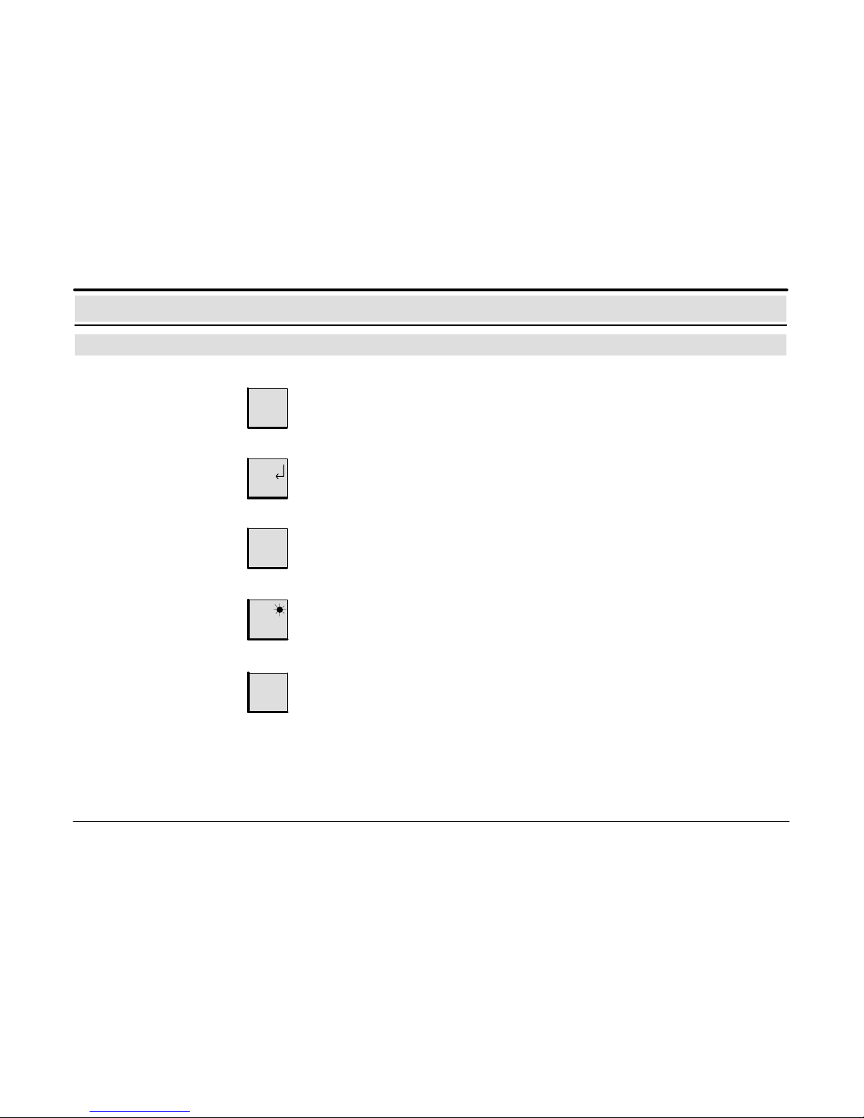
This key returns to the previous level or interrupts a function that has been started.
Return to the
operating level
stop
code
Start/quit operation
authorisation
F
This key calls up the main menu containing the submenus and their additional functions.
Call up the
main menu
Enter the operator code. When this key is pressed, the optical/acoustic signal transmitters and the buzzer are deactivated.
The flashing indicator is switched off.
This key starts code input or quits code operation.
For a detailed description, see the section Operation Authorisation, page 20.
614–30.0212.0270–01 A2 8
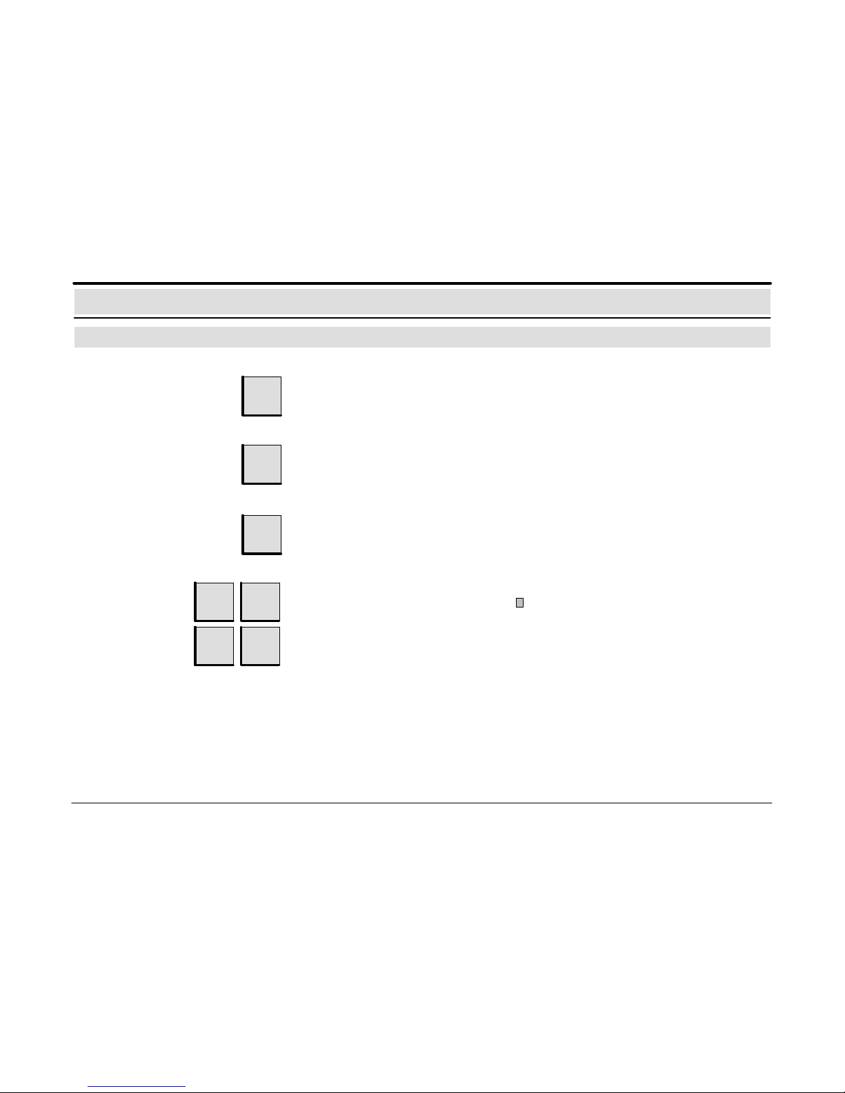
reset
Reset
Display individual/groups
(LEDs), check display and
buzzer
test
This key triggers the reset processes. After successful reset of all messages, the
system returns to the quiescent condition.
For a detailed explanation, see the section Resetting, pages 14 and 15.
When this key is pressed, all the LED indicators, the display of the operating panel and
the buzzer are verified for correct functioning. The indicator test finishes automatically
after 3 seconds. Then the “Software version” is displayed for 3 seconds.
enter
Confirm input
This key is used to confirm the input of characters.
Call up the
message list
When this key is pressed, the display shows a list of all message types with the associat–ed message counters.
For a detailed explanation, see the section Call up a List of all Messages, page 13.
∑
Call up help texts
help?
If this key is pressed, an explanatory text appears in the display. This text provides
further information regarding the menu in which the operator is currently located;
however, the text does not contain any alarm information.
Explanation of Display and Operating Elements
Fixed function keys
614–30.0212.0270–01 A2 9
Entering digits
If digits have to be entered (e.g. entering the detector zone number), they can be entered
at the position indicated by the cursor .
Incorrect inputs (e.g. digits) can be deleted with this key.
Correcting inputs
1
ABC
2
4
JKL5MNO
DEF
CE
Increase the
number value by 1
+1
This function has not yet been realised.
Language toggling
inter–
natio–
nal
This function has not yet been realised.
Explanation of Display and Operating Elements
Fixed function keys
614–30.0212.0270–01 A2 10
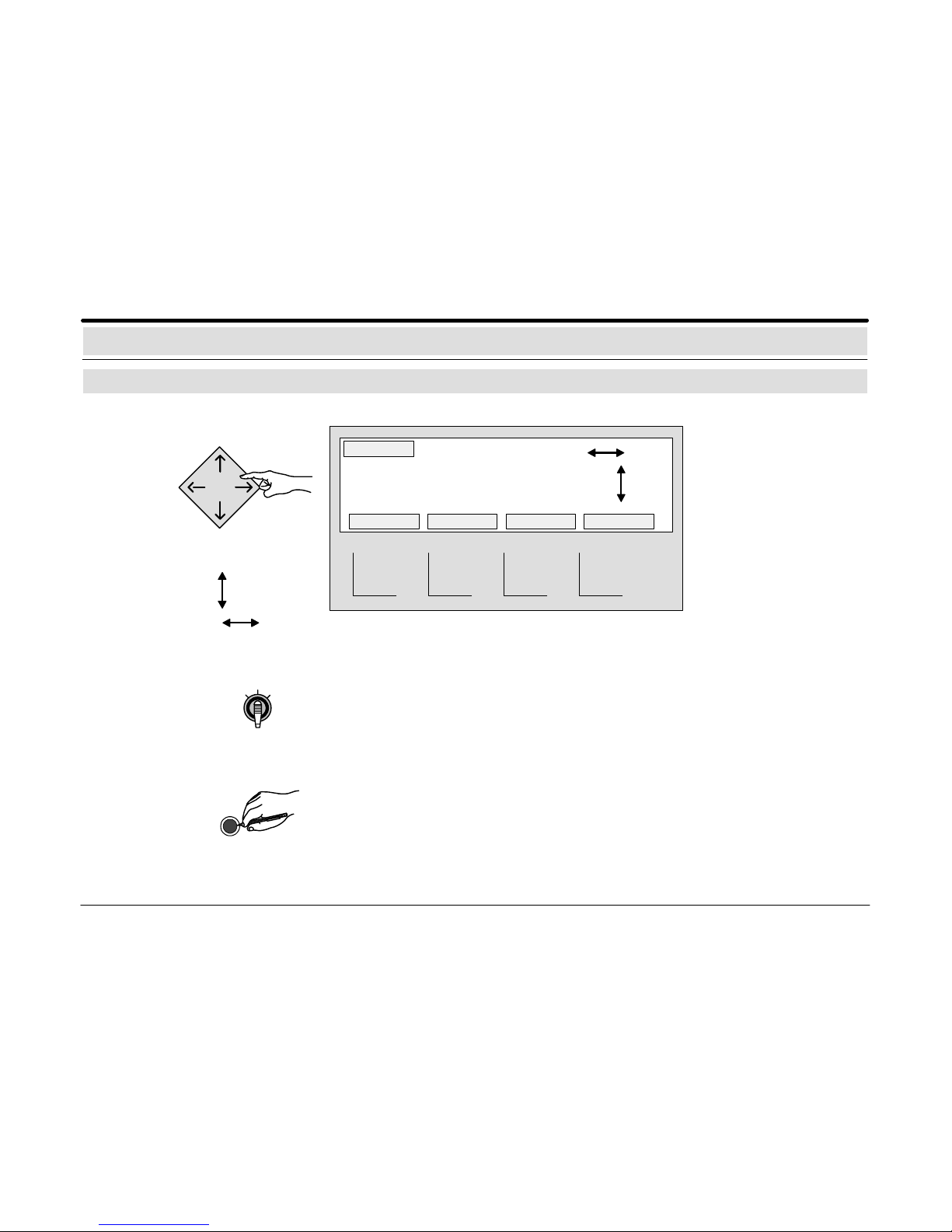
Explanation of Display and Operating Elements
Cursor keys / key switch / sealed switch
Move to the next position by
pressing the appropriate key
up/down
left/right
Cursor keys
The requested position of
the cursor within the display
can be selected using the
appropriate cursor keys
(e.g. when selecting
detectors, detector zones or
functions).
Additional information is
displayed.
123456
78 9101112
Storage room entrance 1st floor
102
Key switch
The assigning of operating functions to the position of the key switch can be programmed,
e.g. – internal program on/off
– code operation on/off
Sealed switch
“General Reset”
If the operator cannot reset the system (e.g. after a sabotage alarm), resetting can be per–
formed without entering an operator code by actuating the sealed switch. This should only
be done after prior consultation with the Service Department. (“General Reset” is only possible if programmed).
614–30.0212.0270–01 A2 11
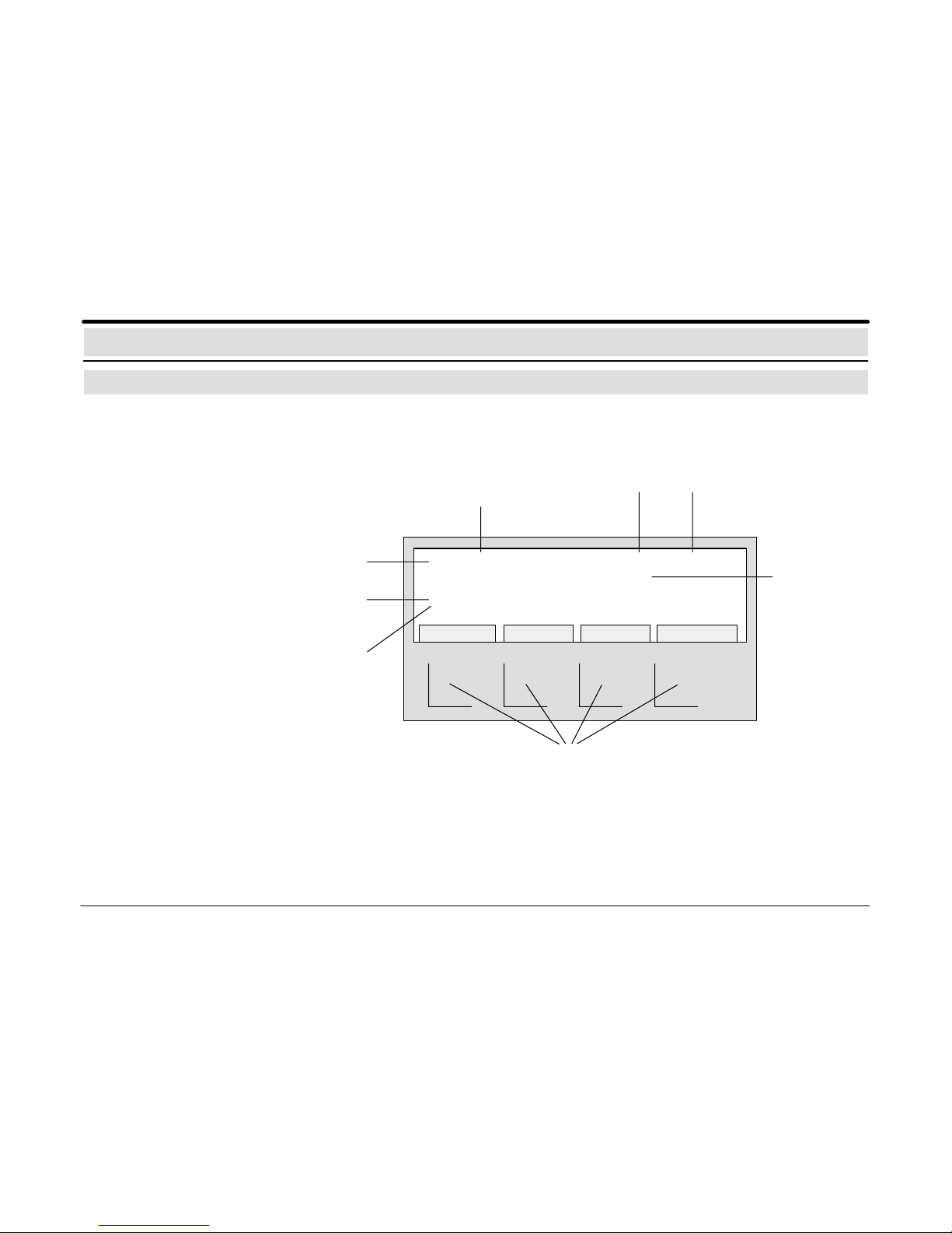
Message Display / Processing
Explanation of the display messages
Priority list of the message types:
– Hold up
– Intrusion
– Sabotage
– Messages
– Malfunctions
– Switch–offs
– Controls
– Maintenance
Message: When messages appear, the alarm organisation has to be respected.
1 INTRUS. INT ZONE 0035 – 16
Storage room entrance 1st floor
3 INTRUS. INT ZONE 0040 – 07
Office building south 1st floor
MESSAGES DETECTOR MESS.TYPE ACTIONS
Type of message
e.g. “Intrusion internal”
Detector No.Zone No.
First message
to arrive
Last message
to arrive
Additional
information
Softkeys for message processing:
Using the 4 softkeys, the functions shown
above these keys in the display can be called
up.
Number of triggered
detector zones in this
message type
614–30.0212.0270–01 A2 12
Key “MESS.TYPE”:
Usin g th e k e y “MESS. T YPE”,
additional triggered message
types are scrolled. If several
message types are present,
they are displayed according
to their priority.
Key “DETECTOR”:
Detector N o. 16 f rom detector zone 0035 r eports an i nter nal intrusion. Using the key “DETECTOR”, all triggered
detectors of this detector zone are displayed.
Using the cursor keys, all triggered d etectors of t his detector zone can then be s elected wit hin the display.
Using the same key (the key becomes an information key)
the display shown above is reset for the selected detectors.
Message: When messages appear, the alarm organisation has to be respected.
Key “ACTIONS”:
Using the key “ACTIONS”, a
text for additional measures
can be called up (e.g., informing custodian, Tel. 3434).
After the key is pressed again,
the previous display appears
again.
1 INTRUS. INT ZONE 0035 – 16
Storage room entrance 1st floor
3 INTRUS. INT ZONE 0040 – 07
Office building south 1st floor
MESSAGES DETECTOR MESS.TYPE ACTIONS
Key “MESSAGES”:
A total of 3 detectors (detector
zones) of the message type
(e.g. “Intrusion internal”) are
present. The display indicates
the first message to arrive (1)
with detector zone No. 0035
and detector No. 16 and the
last message to arrive (3) with
detector zone No. 0040 and
detector No. 07.
Using the key “MESSAGES”,
the following messages (detector zones) of the selected
message type scroll into the
first line of the display.
Ca. 30 seconds after a key has been pressed, the first and the last
message with the highest priority reappear in the display.
Message Display / Processing
Messages with message processing keys
614–30.0212.0270–01 A2 13
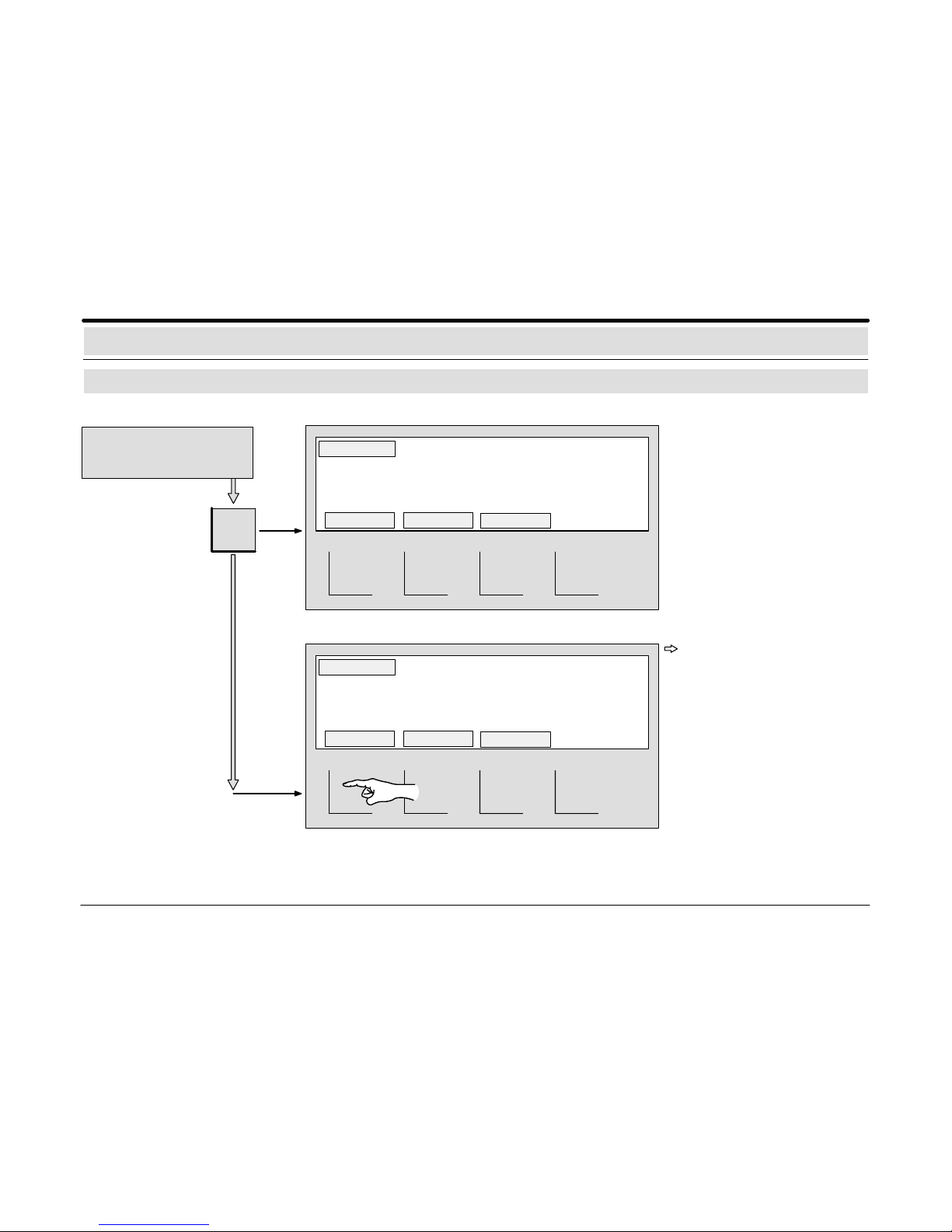
Calling up the
message list
Message Display / Processing
Calling up a list of all message types
∑
Calling up the
selected
message type
1 INTRUS. INT ZONE 0010 – 12
Storage room entrance 1st floor
2 INTRUS. INT ZONE 0013 – 09
Office building south 1st floor
MESSAGES DETECTOR MESS.TYPE ACTIONS
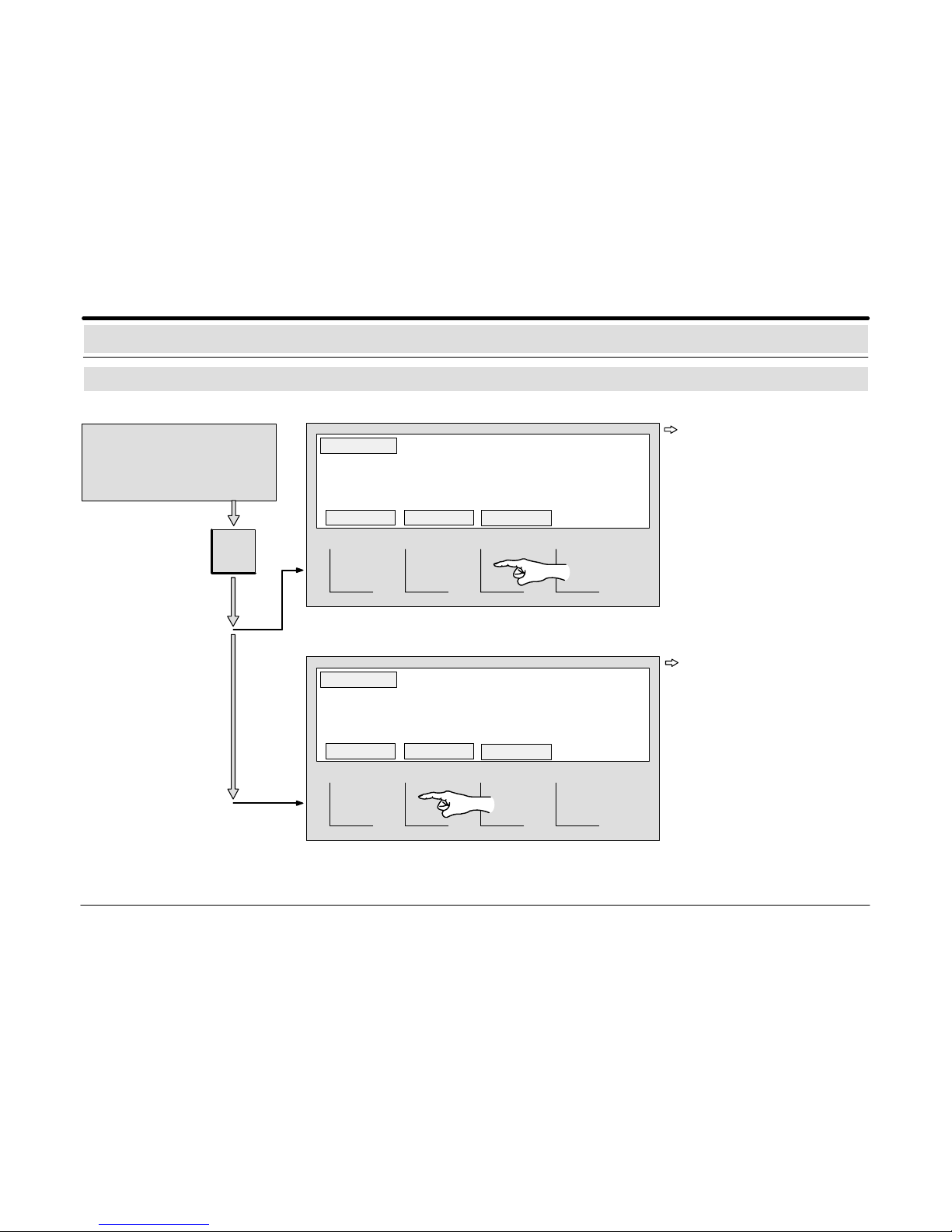
enter
Viewing the
message list,
selecting a
certain type of
message
2 INTRUSION – EXT
2 INTRUSION – INT
1 MALF. – EXT
When the “∑” key is pressed,
the number of triggered detector zones and their message types are displayed in a
list.
The list can b e scrolled using
the appropriate cursor keys
and be selected for another
ty pe o f message.
If the key “enter” is pressed,
a message display of the
message type selected in
the list is shown.
614–30.0212.0270–01 A2 14
Message Display / Processing
Resetting the central control unit
Calling up
reset
Resetting the
central control unit
reset
Enter operating code
(see section
Operating Authorisation)
TOTAL MESS.TYPE SINGLE
TOTAL MESS.TYPE SINGLE
The softkey “TOTAL” resets all
detectors triggered by the
central control unit.
The quiescent condition
picture appears in the display
as soon as the central control
unit is in quiescent condition.
If certain triggered detectors
cannot b e reset by t he author–
ised p ersonnel, inform t he Ser-
vice Department.
1 INTRUS. INT ZONE 0035 – 16
Storage room Entrance 1st floor
RESET MESS.TYPE: INTRUSION
1 INTRUS. INT ZONE 0035 – 16
Storage room Entrance 1st floor
RESET MESS.TYPE: INTRUSION
614–30.0212.0270–01 A2 15
Calling up
reset
Enter operating code (see section
Operating Authorisation) and select zone/message type to be
reset: (see page 12).
Message Display / Processing
Resetting detector zones / message types
Resetting
single zones
Resetting single
message types
The softkey “MESS.TYPE”
resets all triggered detectors of
all detector zones of the selected message type (e.g. INTRUSION internal).
When all reset detectors are in
stand–by mode, the type of
message is no longer shown in
the display.
If the zone cannot be reset by the authorised personnel,
contact the Service Department.
The softkey “SINGLE” resets
all triggered detectors of the
detector zone (e.g. 0035) of
the selected message type.
When all reset detectors are in
stand–by mode, the message
is no longer shown in the display.
reset
TOTAL MESS.TYPE SINGLE
TOTAL MESS.TYPE SINGLE
If the type of message cannot be reset by the authorised
personnel, contact the Service Department.
1 INTRUS. INT ZONE 0035 – 16
Storage room Entrance 1st floor
RESET MESS.TYPE: INTRUSION
1 INTRUS. INT ZONE 0035 – 16
Storage room Entrance 1st floor
RESET MESS.TYPE: INTRUSION
 Loading...