

Bosch TRONIC 6000C WH17, TRONIC 6000C WH27 Installation Manual And Operating Instructions
[en] Installation Manual and Operating Instructions
Tankless electric whole house water heaters
TRONIC 6000C
Models: WH17 / WH27
6 720 646 951 (2015/04) US
6 720 646 951 (2015/04) Tronic 6000C
2 | Table of contents
Table of contents
1 Explanation of symbols and safety instructions . . . . 2
1.1 Key to symbols . . . . . . . . . . . . . . . . . . . . . . . . . . . . 2
1.2 IMPORTANT SAFETY INSTRUCTIONS . . . . . . . . . . 3
2 General information . . . . . . . . . . . . . . . . . . . . . . . . . . . . 4
2.1 Disclaimer . . . . . . . . . . . . . . . . . . . . . . . . . . . . . . . . 4
2.1.1Approval number . . . . . . . . . . . . . . . . . . . . . . . . . . . 4
2.2 Technical identification code . . . . . . . . . . . . . . . . . 4
2.3 Model name and number identification . . . . . . . . . 4
2.4 Package contents . . . . . . . . . . . . . . . . . . . . . . . . . . 4
2.5 Components Diagram . . . . . . . . . . . . . . . . . . . . . . . 5
2.6 Dimensions . . . . . . . . . . . . . . . . . . . . . . . . . . . . . . . 6
2.7 Wiring diagram . . . . . . . . . . . . . . . . . . . . . . . . . . . . 7
2.8 Function . . . . . . . . . . . . . . . . . . . . . . . . . . . . . . . . . . 8
2.9 Technical specifications . . . . . . . . . . . . . . . . . . . . . 9
3 Regulations . . . . . . . . . . . . . . . . . . . . . . . . . . . . . . . . . . . 9
4 Installation . . . . . . . . . . . . . . . . . . . . . . . . . . . . . . . . . . . 10
4.1 Important information . . . . . . . . . . . . . . . . . . . . . . 10
4.2 Selection of place of installation . . . . . . . . . . . . . 10
4.2.1Freeze prevention . . . . . . . . . . . . . . . . . . . . . . . . . 10
4.2.2Recommended minimum
clearances for servicing . . . . . . . . . . . . . . . . . . . . 11
4.3 Mounting the water heater . . . . . . . . . . . . . . . . . . 11
4.4 Water connections . . . . . . . . . . . . . . . . . . . . . . . . 11
4.4.1Water quality . . . . . . . . . . . . . . . . . . . . . . . . . . . . . 12
4.5 Electrical connections . . . . . . . . . . . . . . . . . . . . . . 12
4.6 Starting up . . . . . . . . . . . . . . . . . . . . . . . . . . . . . . . 15
4.6.1Checking for leaks and purging air . . . . . . . . . . . . 15
4.6.2Adjusting the temperature dial . . . . . . . . . . . . . . . 15
4.6.3Adjusting the flow . . . . . . . . . . . . . . . . . . . . . . . . . 15
5 Operation instructions . . . . . . . . . . . . . . . . . . . . . . . . . 16
5.1 Before using the water heater . . . . . . . . . . . . . . . 16
6 Maintenance . . . . . . . . . . . . . . . . . . . . . . . . . . . . . . . . . 17
7 Troubleshooting . . . . . . . . . . . . . . . . . . . . . . . . . . . . . . 19
8 Spare Parts . . . . . . . . . . . . . . . . . . . . . . . . . . . . . . . . . . . 22
1 Explanation of symbols and safety
instructions
1.1 Key to symbols
Warnings
The following keywords are defined and can be used in this
document:
• DANGER indicates a hazardous situation which, if not
avoided, will result in death or serious injury.
• WARNING indicates a hazardous situation which, if not
avoided, could result in death or serious injury.
• CAUTION indicates a hazardous situation which, if not
avoided, could result in minor to moderate injury.
• NOTICE is used to address practices not related to
personal injury.
Important information
Additional symbols
Warnings in this document are identified by
a warning triangle printed against a grey
background.
Keywords at the start of a warning indicate
the type and seriousness of the ensuing risk
if measures to prevent the risk are not taken.
This symbol indicates important information
where there is no risk to people or property.
Symbol Explanation
▶ Step in an action sequence
Cross-reference to another part of the
document
• List entry
– List entry (second level)
Table 1

6 720 646 951 (2015/04)Tronic 6000C
Explanation of symbols and safety instructions | 3
1.2 IMPORTANT SAFETY INSTRUCTIONS
When using this electrical equipment, basic safety precautions
should always be followed, including the following:
▶ READ AND FOLLOW ALL INSTRUCTIONS.
▶ This appliance must be grounded.
▶ Disconnect this product from the electrical supply before
cleaning, servicing or removing the cover.
▶ To reduce the risk of injury, close supervision is necessary
when the product is used near children or elderly persons.
▶ Warning: Mount the unit onto a flat section of wall, well
away from any potential splashes of water or spray and
away from areas where direct moist or wet contact could
occur.
▶ Warning: Indoor installation only, where it will NOT be
exposed to freezing.
▶ Warning: Do not install a check valve or any other type of
back flow preventer within ten feet of the cold water inlet.
▶ The electrical installation must conform to current National
Electrical Codes.
▶ Warning: Do not switch the heater on if you suspect that it
may be frozen. Wait until you are sure that it has completely
thawed out.
▶ The Tronic 6000C is designed to heat potable cold water
for domestic purposes. The heater is not designed to
accept inlet water temperatures above 86° F. The water
heater is not designed for preheated water or recirculation
applications. Contact Bosch Thermotechnology Corp.
before specifying or installing the appliance in any other
application.
IMPORTANT SAFETY INSTRUCTIONS
▶ ADDITIONAL CANADIAN SAFETY INSTRUCTIONS:
– As per the Canadian Electrical Code, C22.1-02 Section
26-744, an auxiliary terminal block must be fitted to
the unit before connecting to the electrical supply (Kit
Part N° “AE Canada Kit”).
(See Fig. 9 and Fig. 10).
– A green terminal (or a wire connector marked “G,”
“GR,” “GROUND” or “GROUNDING”) is provided within
the control. To reduce the risk of electrical shock,
connect this terminal or connector to the grounding
terminal of the electrical service of supply panel with a
continuous copper wire in accordance with the
Canadian Electrical Code, Part I.
– This product shall be protected by a Class A ground
fault circuit interrupter.
SAVE THESE INSTRUCTIONS
▶ Keep this manual in a safe place once the unit has been
installed as it may be needed for future reference.
Safety of electrical appliances for domestic use and similar
purposes
Product installation and use must be in accordance with EN
60335-1 in order to prevent hazards from occurring when
using electrical appliances.
6 720 646 951 (2015/04) Tronic 6000C
4 | General information
2 General information
2.1 Disclaimer
2.1.1 Approval number
Commonwealth of Massachusetts
In the Commonwealth of Massachusetts a licensed plumber
and electrician must perform the installation.
2.2 Technical identification code
[EI] Electronic Instantaneous
[17/27] Maximum output (kW)
[E/M] Electronic / mechanical temperature control
[W] Wall hung
[I] Indoor
[H] Horizontal installation
[B] Water connections
2.3 Model name and number identification
2.4 Package contents
• Tankless electric water heater.
• 4 screws.
• Installation Manual.
• Warranty Registration Card.
• Warranty Statement.
EI 17 E/M W IHB
EI 27 E/M W IHB
Table 2
Model Name Model Number
WH17 EI 17 E/M W I H B
WH27 EI 27 E/M W I H B
Table 3
6 720 646 951 (2015/04)Tronic 6000C
General information | 5
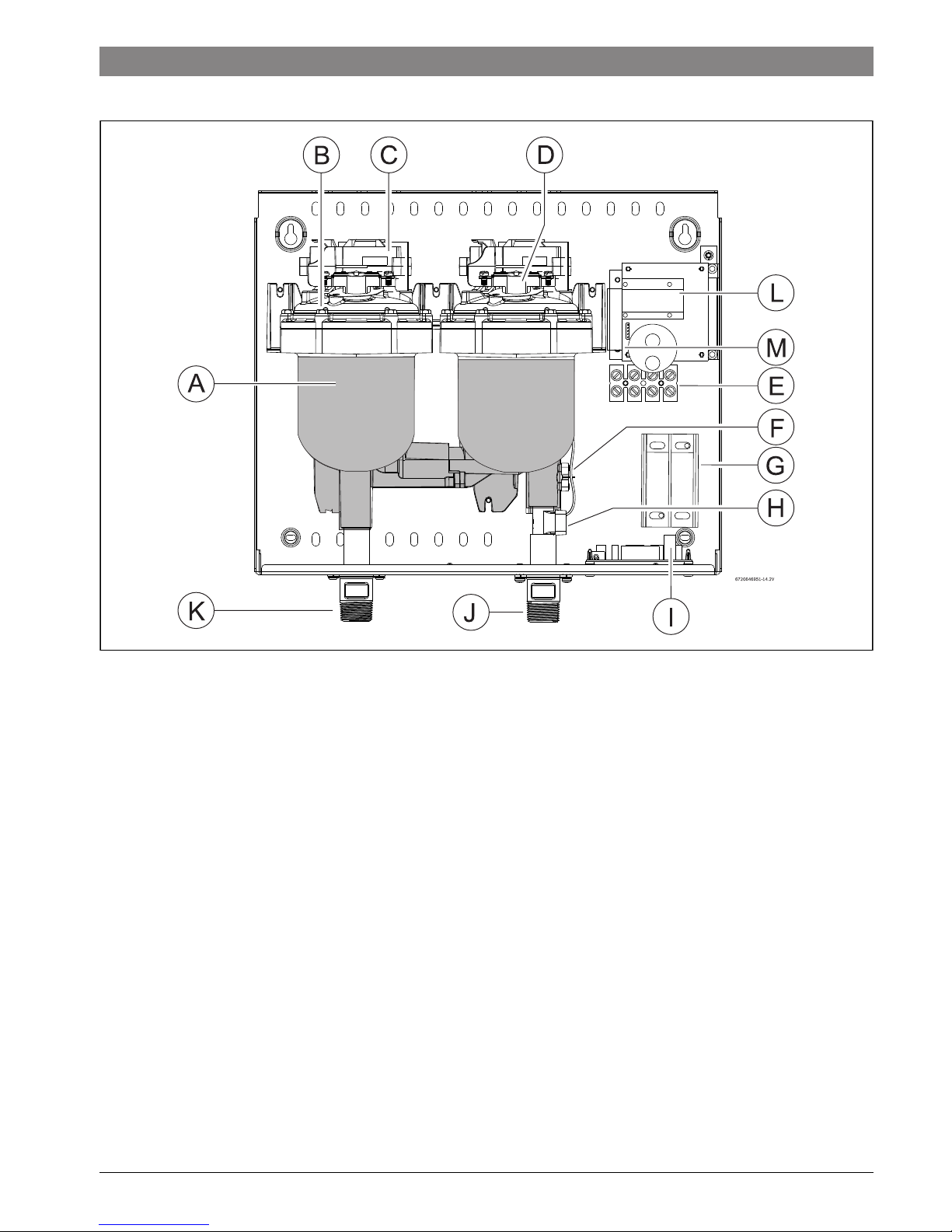
2.5 Components Diagram
Fig. 1
[A] Heating module
[B] Heating element assembly
[C] Heating module PCB
[D] Double pole thermal cut-off (WH27).
Single pole thermal cut-off (WH17).
[E] 6 way terminal block (WH27).
4 way terminal block (WH17).
[F] Temperature sensor
[G] Terminal block (CANADA ONLY)
[H] Flow transducer
[I] Control PCB
[J] Cold water inlet
[K] Hot water outlet
[L] Display PCB
[M] Display DIP switch
6 720 646 951 (2015/04) Tronic 6000C
6 | General information
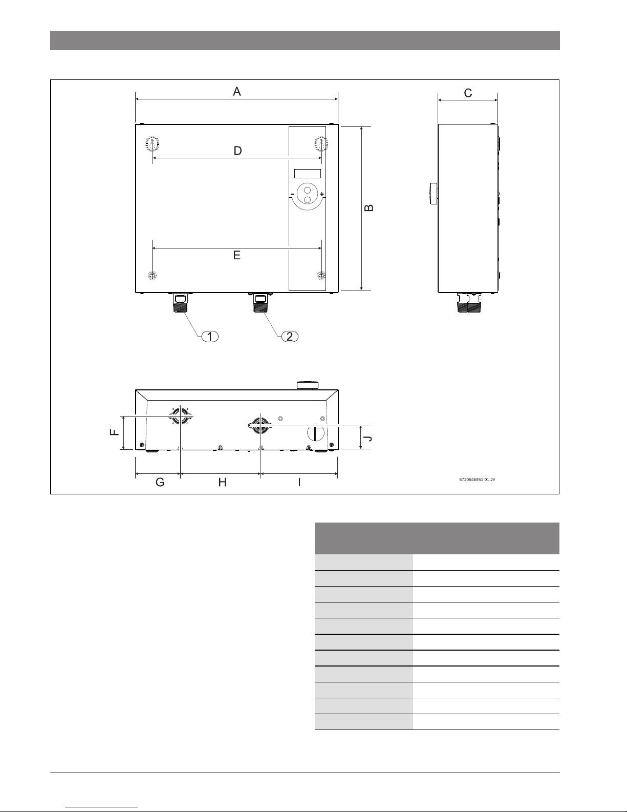
2.6 Dimensions
Fig. 2
[1] Outlet ¾ " NPT (hot water)
[2] Inlet ¾ " NPT (cold water)
Dimensions
(inches) WH17 / WH27
A (Width) 15 ¼ "
B (Height) 12 ½ "
C (Depth) 4 ½ "
D 12 5/8"
E 12 5/8"
F 2 ½ "
G 3 ½ "
H6
1
/8"
I5
3
/4"
J1
3
/4"
Water connections ¾ "
Table 4 Dimensions
6 720 646 951 (2015/04)Tronic 6000C
General information | 7
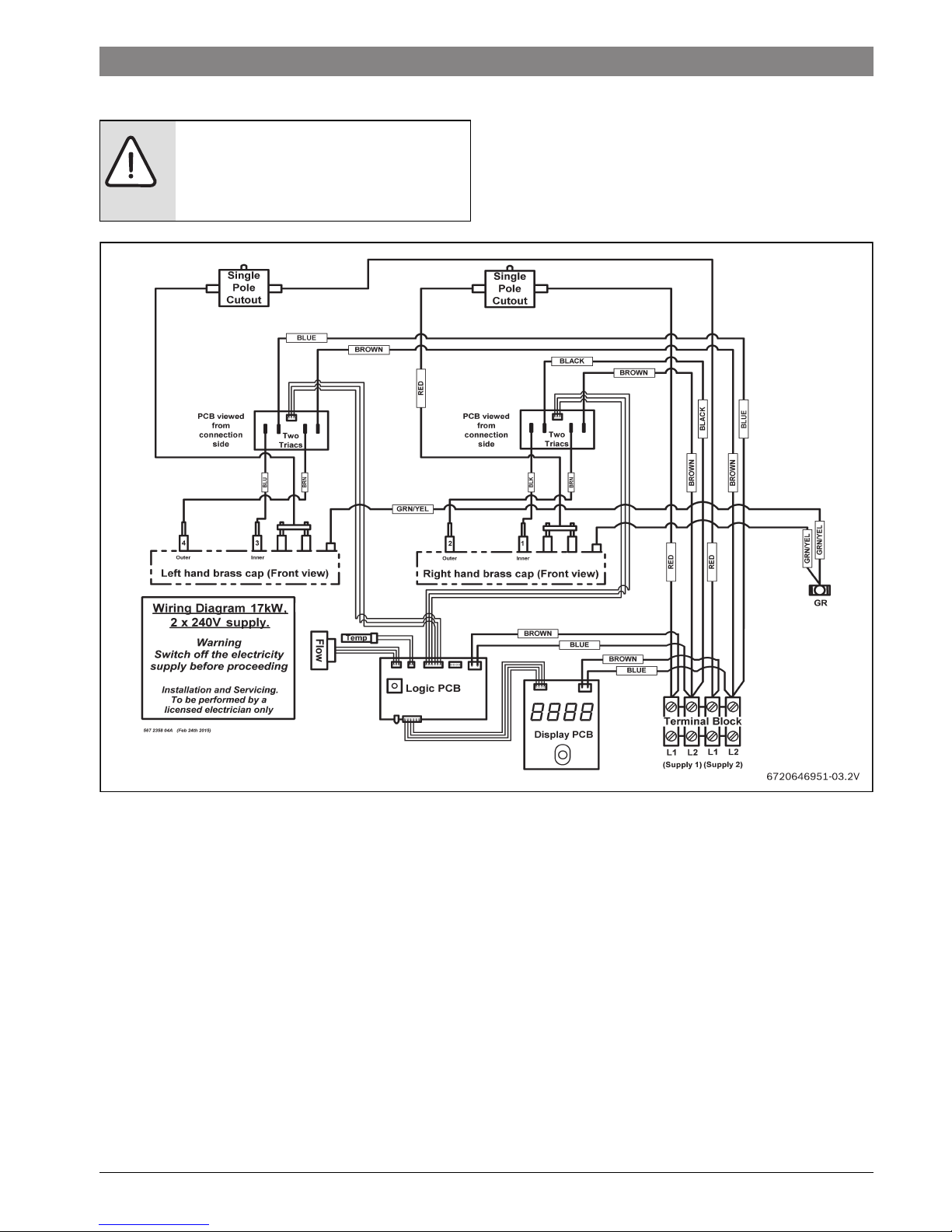
2.7 Wiring diagram
Fig. 3 Internal wiring schematic for single phase WH17 unit.
DANGER: Risk of electric shock!
▶ Always switch off the electricity supply
to the unit before any intervention in the
heater.
6 720 646 951 (2015/04) Tronic 6000C
8 | General information
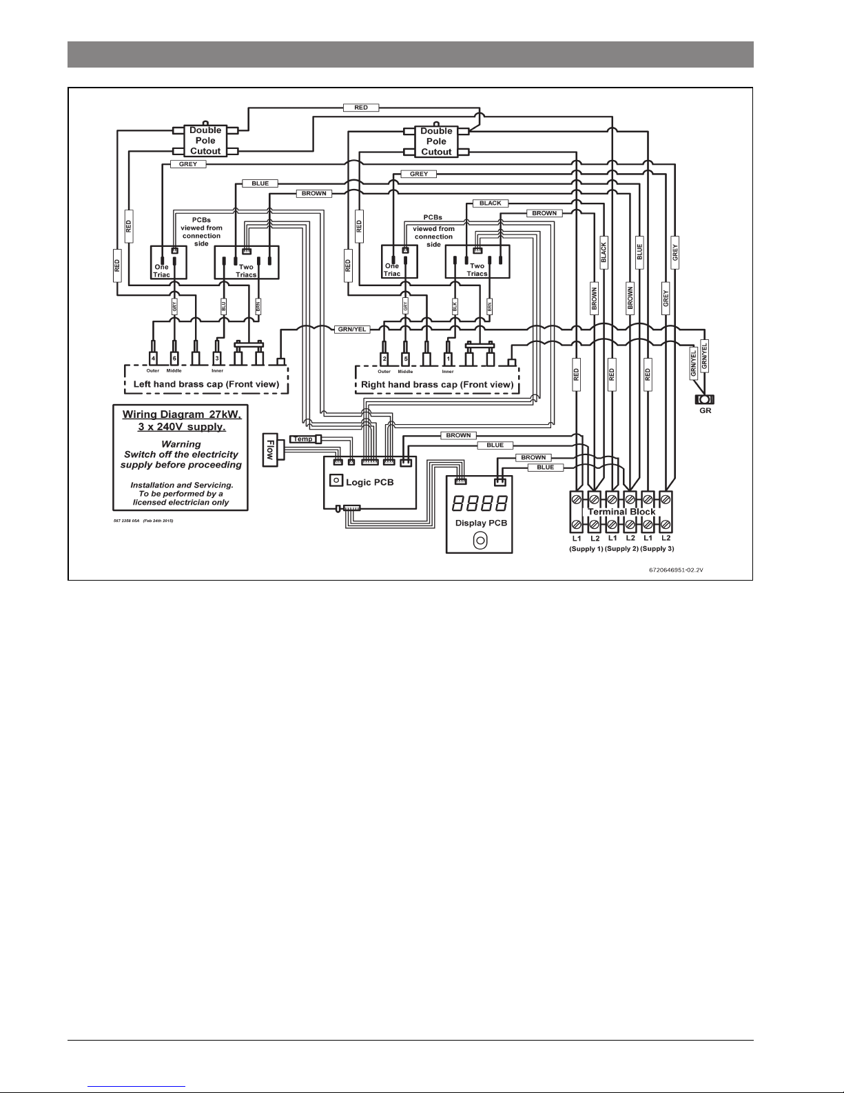
Fig. 4 Internal wiring schematic for single phase WH27 unit.
2.8 Function
How the water heater works:
• The Tronic 6000C heats water continuously as it flows
through the 2 heater modules.
• The electronic control PCB monitors the flow rate and the
incoming water temperature and then switches on the
required number of heater elements to reach the
temperature set by the temperature adjustment dial.
• The temperature dial sets the heater set-point
temperature. Please note heat loss, pipe run, and other
factors affect the outlet temperature at end use.
• As the flow rate or the incoming water temperature
changes, the electronic control adjusts the number of
heater elements used so that the outlet temperature is
maintained.
• The outlet water temperature can change slightly as the
flow rate changes due to the steps in power as different
heater elements are switched on and off.
• The outlet water temperature can also vary if the maximum
flow rate is exceeded (see
Fig. 11) or if the supply
voltage changes.
• Each heater module is protected by an electro-mechanical
thermal cut-out. This cut-out will only trip in exceptional
circumstances.
Contact Technical Support 800-798-8161 for further
instruction.
• The WH17 unit is supplied from two independent voltage
supplies and the WH27 unit from three independent
voltage supplies. (In Canada the unit has just one voltage
supply).
• Depending on the region of the country, the temperature of
the water supply can vary between an average of 40 °F in
winter to 70 °F in summer, with an average of 55 °F. The
output temperature and maximum flow of the heater is
dependent on inlet water temperature.
 Loading...