

Page 1

R
E
P
A
I
R
I
N
S
T
R
U
C
T
I
O
N
R
E
P
A
I
R
I
N
S
T
R
U
R
E
P
A
I
R
I
N
S
Fully-automatic coffeemaker
C
T
R
U
C
T
I
O
N
T
I
O
N
1 SAFETY........................................................2
1.1 Safety instructions..............................................................2
1.2 Repair instructions .............................................................2
2 INSTALLATION............................................3
2.1 Installation...........................................................................3
2.2 Scope of delivery................................................................ 3
3 OPERATION.................................................4
3.1 Starting the appliance.........................................................4
3.2 Controls...............................................................................5
3.3 Displays and operating logic........................................... 12
3.4 Adjusting water hardness................................................20
3.5 Reducing temperature......................................................21
3.6 Reset..................................................................................21
3.7 Manually cooling the heater.............................................22
3.8 Service programme .......................................................... 23
3.9 Maintenance and daily cleaning...................................... 28
4 COMPONENTS...........................................30
4.1 Flowmeter..........................................................................30
4.2 Heater and NTC-sensor.................................................... 31
4.3 Brewing unit...................................................................... 33
4.4 Gear unit............................................................................38
4.5 Steam valve and proximity switch................................... 42
4.6 Hot water / steam nozzle ..................................................43
4.7 Water filter.........................................................................44
5 FUNCTIONS ...............................................45
5.1 Construction......................................................................45
5.2 Fluid system......................................................................47
5.3 Temperature...................................................................... 48
6 REPAIR.......................................................49
6.1 Replacing the brewing unit.............................................. 49
6.2 General disassembly........................................................ 52
6.3 Replacing the pump ......................................................... 55
6.4 Replacing the thermal fuse.............................................. 56
6.5 Replacing the heating element and NTC sensor............ 59
6.6 Replacing the electronics board ..................................... 60
6.7 Replacing the power cord................................................ 61
6.8 Replacing the coffee outlet.............................................. 62
6.9 Replacing the front panel................................................. 63
6.10 Replacing steam valve and operating panel .................. 64
6.11 Appliance test................................................................... 65
7 FAULT DIAGNOSTICS...............................67
7.1 Incoming goods inspection............................................. 67
7.2 Incoming goods inspection............................................. 68
7.3 System and error messages............................................ 69
7.4 Measuring the coffee temperature.................................. 73
8 TECHNICAL SPECIFICATIONS.................74
8.1 Rating plate....................................................................... 74
8.2 Power................................................................................. 75
8.3 Temperatures.................................................................... 75
8.4 Consumption values (230 V/50 Hz models).................... 76
8.5 Dimensions and weight.................................................... 77
8.6 Filling amounts................................................................. 77
8.7 Components...................................................................... 78
58300000123125_ARA_en_d.doc – 09.10.09 Seite 1 von 78
Page 2

1 SAFETY
1.1 Safety instructions
Danger!
► Repairs may be carried out by a qualified electrician only!
► The user may be put at considerable risk and injured by
improper repairs!
► Electric shock may occur if live components are touched
inside the appliance!
► Do not touch components in the appliance. Even the modules
can be live!
► Before commencing repairs, ALWAYS disconnect the
appliance from the power supply!
► If tests have to be conducted while the appliance is live,
ALWAYS use a residual-current-operated circuit-breaker!
► The protective conductor connection must not exceed the
standardised values! This is essential for personal safety and
appliance function!
► When repairs are complete, perform a test in accordance with
VDE 0701 or the corresponding national regulations!
► Following each repair, conduct a leak and performance test.
1.2 Repair instructions
Caution!
► NEVER attempt repairs by randomly replacing components!
► ALWAYS proceed systematically and comply with the
technical documentation for the appliance!
► Components become hot during operation. Before
commencing repairs, leave the appliance to cool down.
► As a rule, printed-circuit boards are not repaired but are
completely replaced with original spare parts. Exceptions are
documented separately.
Risk of scalding!
Hot water / steam nozzle or auto-cappuccinatore frothing-up
nozzle (optional) become very hot. Take hold of the nozzles
by the plastic parts only, not by the metal parts. Keep body
parts away from the nozzles and do not aim it to yourself or
anyone else.
When steam or hot water is released, the nozzles may initially
sputter!
58300000123125_ARA_en_d.doc – 09.10.09 Seite 2 von 78
Page 3

2 INSTALLATION
2.1 Installation
► The installation location must be level and dry.
► Protect the appliance from splash water.
► There must be a minimum filling height of 410 mm.
► Connect and operate the appliance only in accordance with
the specifications on the rating plate.
► Operate the appliance indoors and at room temperature only.
► Do not place the appliance on a hot surface (e.g. heating
plate) and never use it close to an open flame.
2.2 Scope of delivery
Accessories included in packing without extra box:
► 2 Detergent-tablets
► Test strip for determining the local water hardness
► 2 Descaler-tablets (for 1 descaling process)
► Operating instructions in 7 languages
58300000123125_ARA_en_d.doc – 09.10.09 Seite 3 von 78
Page 4

3 OPERATION
3.1 Starting the appliance
Risk of damage!
Do not use coffee beans which have been glazed,
caramelised or treated with other additives containing
WARNING
► Pull the mains plug out of the cord store at the rear of the
appliance and connect according to the specifications on the
rating plate.
► Remove the water tank and fill with fresh, cold, non-
carbonated water. Observe “max” mark.
► Attach water tank straight and press all the way down.
► Fill the bean container with fresh coffee beans. Preferably
use espresso beans or bean mixtures for fully automatic
machines.
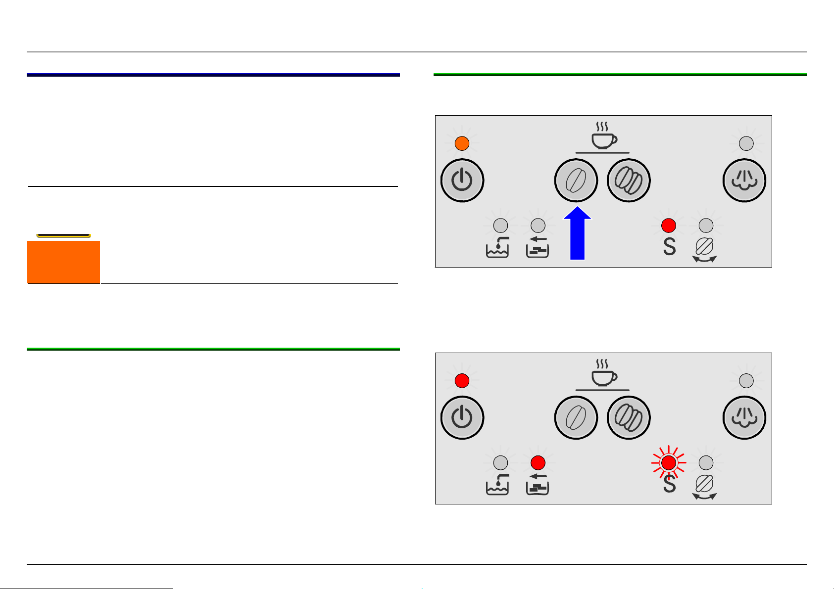
► Set the mains switch at the rear
of the appliance to I.
LED above stand-by button lights up
dim red.
► Ensure that the rotary knob for
drawing steam/hot water is set
to O.
► Press Standby button.
sugar. These will damage the grinding unit.
Note:
When the appliance is used for the first time or if the
appliance has not been used for a prolonged period, the
first cup of coffee still does not have the full aroma and
should therefore not be drunk.
3.1.1 Self-test
► Brewing module is initialised.
► Appliance heats up to operating temperature.
► Brewing module is moved to brewing position.
► Pump starts running and conveys approx. 50 ml water
through the coffee outlet.
Brewing module and coffee outlet are rinsed and heated.
► Brewing module drains and moves to home position
Appliance is ready for use when the LED above the stand-by button
is lit green.
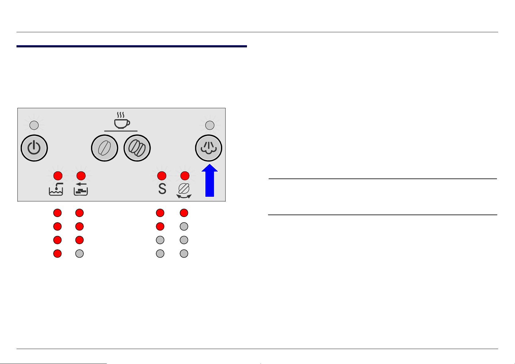
3.1.2 Filling the system
When switching on the appliance for the first time and after a service
the water pipe system in the appliance must be filled.
LEDs above stand-by button and “Turn steam/hot water valve”
flash:
► Place a cup under the hot water/ steam nozzle.
► Set rotary knob for drawing steam/hot water to “Steam”.
A small amount of water is conveyed and the water pipe
system is filled.
► Set rotary knob for drawing steam/hot water to “O”.
LED above stand-by button flashes, appliance heats up and is
rinsed.
Appliance is ready for use when the LED above the stand-by
button is lit green.
58300000123125_ARA_en_d.doc – 09.10.09 Seite 4 von 78
Page 5

3.2 Controls
3.2.1 Overview of the controls 1
2
3
4
5
6
7
8
9
10
11
12
a
b
c
d
Mains switch I / O
Standby button
Coffee on button (mild)
Coffee on button (strong)
Steam button
Hot water/steam production knob
LED display
Fill water
Empty trays
Run Service programme
Turn steam/hot water valve
Steam pipe with frothing nozzle
Coffee outlet, height-adjustable
Cover, water tank
Water tank
Bean container with aroma protection cover
13
14
15
16–19
20
21
Slot for detergent tablets
Cup shelf with cup heater
Slide switch, degree of ground coffee
Drip tray
Store for power cord
Service flap (access to brewing module)
58300000123125_ARA_en_d.doc – 09.10.09 Seite 5 von 78
Page 6

3.2.2 Overview of the controls 16
17
18
19
Drip plate
Drawer for coffee dregs
Drip tray
Float for level indicator
Note!
The level of the drip tray is indicated via the float
through an opening in the drip plate. The level is not
monitored electronically!
16
17
18
19
58300000123125_ARA_en_d.doc – 09.10.09 Seite 6 von 78
Page 7

3.2.3 Controls
1. Mains switch
The mains switch on the rear of the appliance switches the power
supply on or off.
When the mains switch has been switched on, the Standby button
lights up dim red. The appliance is in standby mode.
Attention!
Risk of damage!
Do not actuate the mains switch during the brewing
process. When the appliance is switched on again,
malfunctions and damage may occur.
► Do not switch off the appliance with the mains
switch until it has been switched off with the
WARNING
Standby button.
2. Standby button
The Standby button switches on and starts the appliance or
switches it from brewing mode to standby.
When the Standby button has been pressed, a self-test runs: The
appliance is initialised, heats up and is rinsed. The LED of the
Standby button flashes during this process.
If the LED is lit green, the appliance is ready for use.
Switching on a cold appliance:
When the Standby button has been pressed, the appliance heats up
and is rinsed. The button flashes. Coffee cannot be brewed until the
button stops flashing.
Switching on a warm appliance:
If the appliance is switched on with the Standby button, a rinsing
process or self-test will not occur until the heater has reached the
operating temperature. The Standby button is lit constantly. Coffee
can be brewed immediately.
The appliance is not rinsed if:
► it was still warm when switched on
or
► there was no coffee from the last brew before the appliance
was switched off.
Automatic switch-off:
Appliance automatically switches to standby after 3 hours.
58300000123125_ARA_en_d.doc – 09.10.09 Seite 7 von 78
Page 8

Controls
3. Coffee on button (mild)
If the coffee on button (mild) is pressed, a coffee brewing
process is started with a small amount of ground coffee.
Amount of ground coffee saved permanently: mild =
7.6 +/– 1g
► Press 1 x for a cup of mild coffee.
Coffee beans are ground, pre-brewed and conveyed into the cup.
4. Coffee on button (strong)
If the coffee on button (strong) is pressed, a coffee brewing
process is started with a large amount of ground coffee.
Amount of ground coffee saved permanently: strong =
12.3 +/– 1g
► Press 1 x for a cup of strong coffee.
Coffee beans are ground, pre-brewed and conveyed into the cup.
If the button is pressed again, the coffee brewing process can be
interrupted early. The grinding process is ended, the brewing process
is stopped, the brewing module is emptied.
The same amount of liquid can also be drawn:
► To do this, press the coffee on button (strong) again within
3 seconds after the end of the brewing process.
The already used ground coffee is brewed.
The factory preset amount of liquid (125 ml) can be changed.
► To do this, press the “on” button and hold down until the
required amount of coffee has run through.
Programming range 30–220 ml
Reset to factory setting ► Remove drip tray
► Simultaneously press Mild +
Strong “on” buttons and hold
down for 5 second
LEDs flash
► Re-insert drip tray
► Switch on appliance with
standby button
58300000123125_ARA_en_d.doc – 09.10.09 Seite 8 von 78
Page 9
Controls
5. Steam button
By pressing the button, steam is generated for frothing or
heating.
The appliance heats up for approx. 20 seconds. Then steam can be
drawn by rotating hot water/steam production knob.
When the knob has been turned back to O, the steam button must be
pressed again before more steam can be drawn.
6. Hot water/steam production knob
Valve with 2 positions
O
When the hot water/steam production knob has been turned, hot
water or steam can be drawn via the steam pipe.
Before steam can be drawn, the steam button must also be pressed.
When the knob has been turned back to O, the steam button must be
pressed again before more steam can be drawn.
Coffee brewing process (valve closed)
Hot water/steam production (valve open)
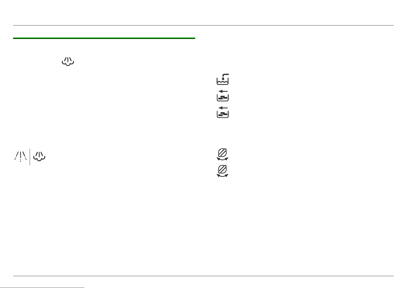
7. LED display
Lit and flashing LEDs indicate the following:
lit Water tank is empty and must be filled.
lit Trays are full: Empty trays and re-insert.
flashes No trays: Re-insert trays.
S
S
8. Steam pipe with frothing nozzle
Steam pipe can be swivelled 30° to the side.
Standard frothing nozzle for drawing hot water and for drawing steam
to heat drinks and froth milk.
lit Service programme must be run:
flashes Service programme is running
flashes
lit
Knob must be turned to hot water/steam
production.
Knob must be turned to O.
58300000123125_ARA_en_d.doc – 09.10.09 Seite 9 von 78
Page 10

Controls
9. Coffee outlet, height-adjustable
Adjustment range 80 mm–120 mm
10. Cover, water tank
Hinged, connected to upper section of appliance.
11. Water tank
Can be removed at side, 1.8 litre capacity up to “ max” mark.
Holder for screw-on water filter (mat. no. 46 1732) available.
12. Bean container with aroma protection cover
Transparent, capacity approx. 700 ml (equivalent to approx. 250
beans)
13. Slot for cleaning tablet
No sensor for cover monitor
14. Cup shelf with cup pre-heater
15. Slide switch – degree of ground coffee, 3-stage
Risk of damage!
Beans may become jammed in the grinding unit.
► Adjust degree of grinding only while the grinding
WARNING
unit is running
Irrespective of the degree of roasting and the oil content of the coffee
beans used, the coffee mill’s degree of grinding must be changed:
► Light roasting, low oil content finer grinding result
► Dark roasting, high oil content coarser grinding result
If beans are very oily, a very fine grinding unit setting
in conjunction with a large amount of ground coffee
may impair the operating sequence!
The new setting does not become noticeable until the second or third
cup of coffee.
Passively heated by the waste heat from the coffee heater
Temperature > 37 °C after 20 minutes
58300000123125_ARA_en_d.doc – 09.10.09 Seite 10 von 78
Page 11

Controls
16. Drip plate
Stainless steel, with opening for float
17. Drawer for coffee dregs
Capacity 12–14 coffee dregs at medium strength
18. Drip tray
Volume until float indicates limit, approx. 0.7 litres
The presence of the drip tray is monitored by a microswitch.
This also occurs in standby.
19. Float for level indicator
The level of the drip tray is indicated via the float through an opening
in the drip plate.
The level is not monitored electronically.
20. Store for power cord
Pull out power cord to required length.
21. Service flap
The service flap is locked in position on the right side of the appliance.
To open:
► Take hold of the recessed grip and
► pull the service flap outwards.
58300000123125_ARA_en_d.doc – 09.10.09 Seite 11 von 78
Page 12
3.3 Displays and operating logic
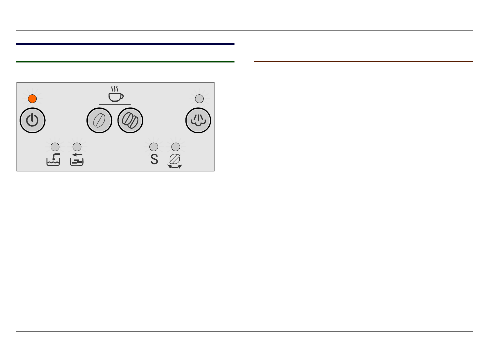
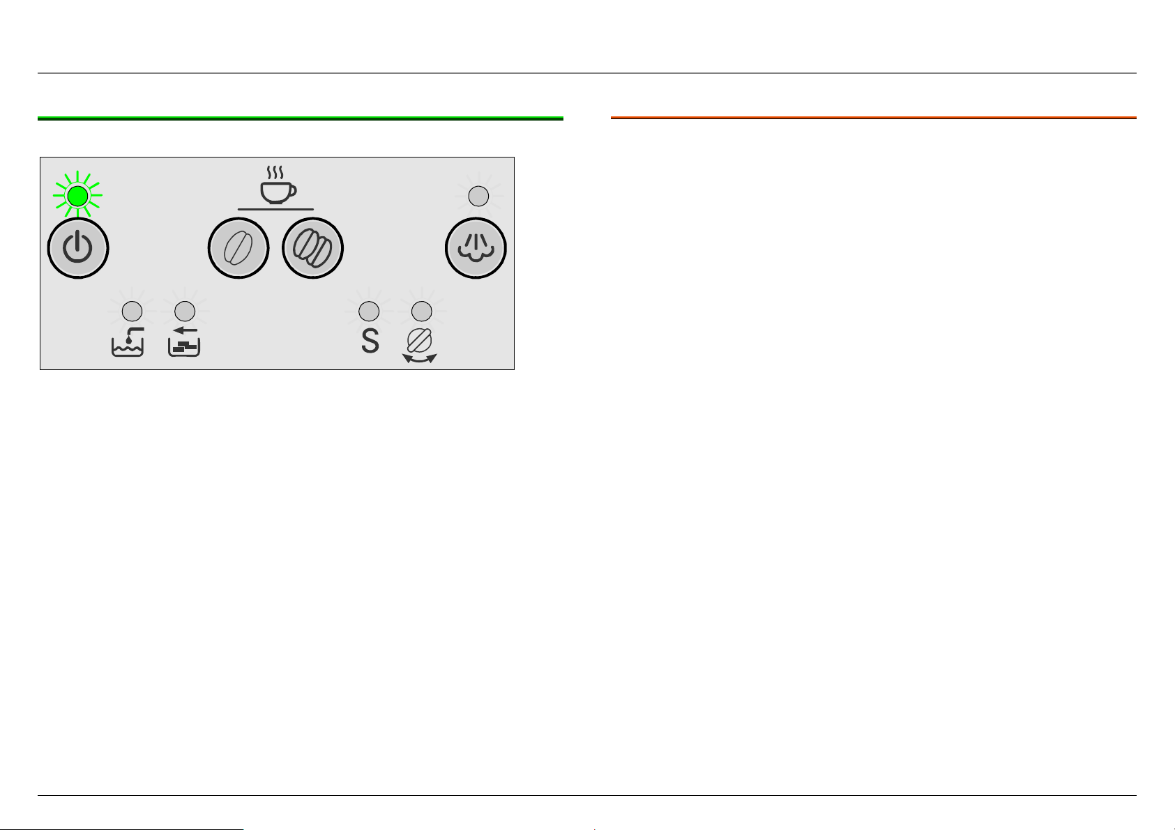
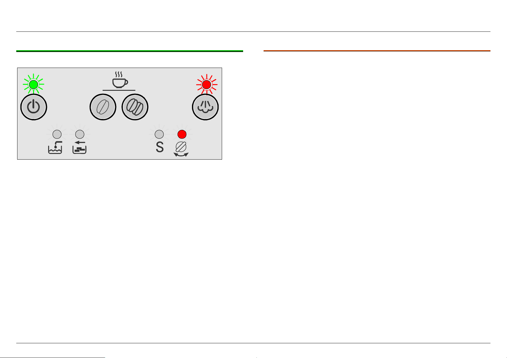
3.3.1 Standby
Set mains switch to I
LED button:
LED display:
Standby is lit dim red
No display
3.3.1.1 Options
Press Standby button: The appliance is initialised, heats up
and is rinsed
Press Coffee mild button: No response, appliance is off
Press Coffee mild button for
Service programme starts
5 seconds:
Press Coffee strong button: No response, appliance is off
Press the “Steam” button No response, appliance is off
Press Steam button for 5 sec.: Water hardness setting starts
Setting corresponds to the number
of lit LEDs
Press Coffee strong + Steam
buttons for 5 sec.:
Temperature reduction by 4°
Normal temperature = “Add water”
and “Empty trays” LEDs are lit. Pr ess
Coffee strong button = - 4°/ normal
Open hot water/steam valve: No response, appliance is off
Open hot water/steam valve,
Start appliance test
press Coffee mild + Steam
buttons for 5 sec.:
Remove trays: No response, appliance is off
Remove trays, Press Coffee
mild + strong buttons for 5 sec.:
Works reset for amount of coffee,
temperature and water hardness
Release brewing unit: No response, appliance is off
Service LED flashes alternately with
Standby LED buttons (dim red)
Press Coffee mild + strong +
Steam buttons for 5 sec.:
Set software bit for initial
operation: = Fill system +1.
Grinding unit running time +6 sec.
58300000123125_ARA_en_d.doc – 09.10.09 Seite 12 von 78
Page 13
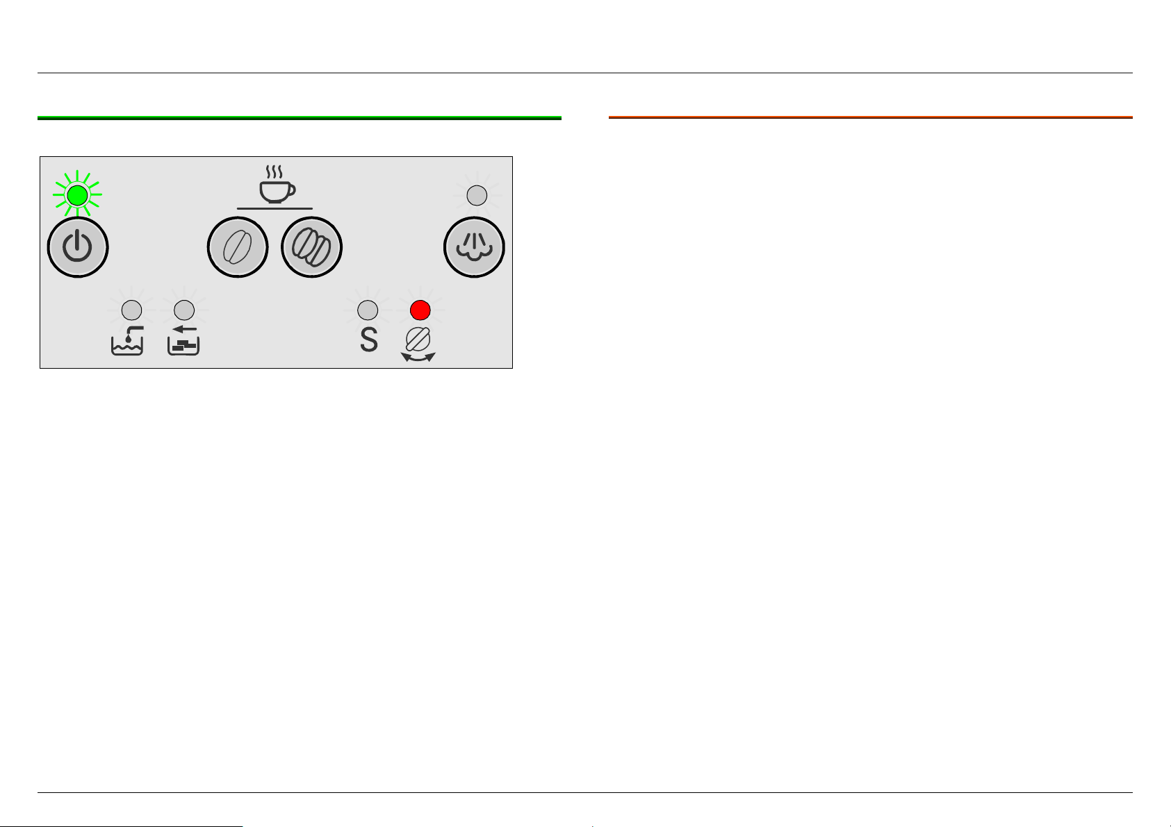
3.3.2 Switching on the appliance
Press Standby button
LED button:
LED display:
Appliance:
Standby flashes red
No display
The appliance is initialised, heats up and is rinsed
3.3.2.1 Options
Press Standby button: Appliance switches to standby
Press Coffee mild button: No response
Press Coffee strong button: No response
Press the “Steam” button: No response
Open hot water/steam valve: Close steam valve LED is lit
Remove trays: “Trays missing” LED flashes,
heating up is interrupted,
brewing unit does not move
Release brewing unit: Heating up ends.
Service LED flashes alternating
with Standby LED buttons (dim
red)
Lock brewing unit: Appliance switches to standby
58300000123125_ARA_en_d.doc – 09.10.09 Seite 13 von 78
Page 14
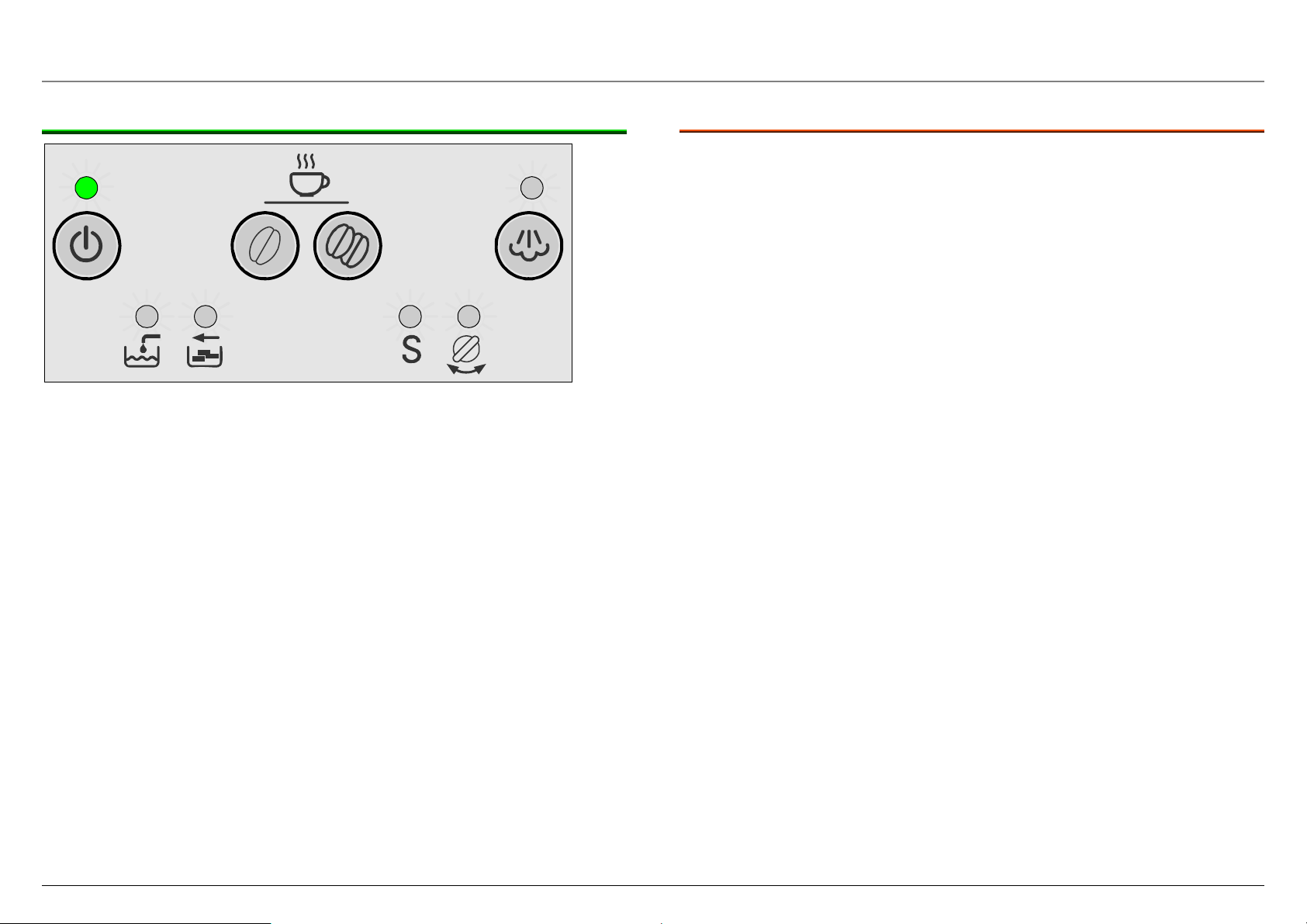
3.3.3 Appliance ready to use
LED button:
LED display:
Appliance:
Standby is lit green
No display
Ready to use
3.3.3.1 Options
Press Standby button: Appliance switches to standby
Press Coffee mild button: Brew coffee
Press Coffee strong button: Brew coffee
If the Coffee mild or Coffee
strong button is pressed again
within 3 seconds after the end of
the brewing cycle, the same
amount of liquid is brewed
through the ground coffee
already used.
Press the “Steam” button: Heat up to steam temperature
Open hot water/steam valve: Draw hot water
Remove trays: Standby button LED is lit, “Trays
missing” LED flashes
Release brewing unit: Service LED flashes alternating
with Standby LED buttons (dim
red)
Lock brewing unit: Appliance switches to standby
58300000123125_ARA_en_d.doc – 09.10.09 Seite 14 von 78
Page 15
3.3.4 Brewing coffee
Press the Coffee mild or Coffee strong button
LED button:
LED display:
Appliance:
Standby flashes green
No display
Brew coffee
3.3.4.1 Options
Press Standby button: The current coffee brewing process
is stopped, switches to standby.
Press Coffee mild button: The current coffee brewing process
is stopped, switches to standby.
Press Coffee strong button: The current coffee brewing process
is stopped, switches to standby.
If the Coffee mild or Coffee strong
button is pressed again within
3 seconds after the end of the
brewing cycle, the same amount of
liquid is brewed through the ground
coffee already used.
Press the “Steam” button: The current coffee brewing process
is stopped, switches to standby.
Open hot water/steam valve: The current coffee brewing process
is interrupted, Close steam valve
LED is lit, grinding is not
interrupted.
Remove trays: The current coffee brewing process
is interrupted, “Trays missing” LED
flashes, grinding is not interrupted.
Remove water tank: Coffee brewing process is stopped
after approx. 10 seconds, “Add
water” LED is lit, Open hot water/
steam valve LED flashes.
Adjust filling quantity: Active is accepted.
Beans running out: Current coffee brewing process is
completed.
58300000123125_ARA_en_d.doc – 09.10.09 Seite 15 von 78
Page 16
3.3.5 Drawing hot water
Open hot water/steam valve
LED button:
LED display:
Appliance:
Standby flashes green
Hot water/steam valve is lit
Pump is running, heating on
Convey hot water
3.3.5.1 Options
Press Standby button: Appliance switches to standby
Press Coffee on button: Brewing is stopped, “Close hot
water/steam valve” LED is lit
Press coffee strength button: Brewing is stopped, “Close hot
water/steam valve” LED is lit
Press the “Steam” button: Brewing is stopped, “Close hot
water/steam valve” LED is lit
Remove trays: Brewing is stopped, “Close hot
water/steam valve” LED is lit,
“Trays missing” LED flashes
Remove water tank: Brewing is stopped after approx.
10 sec., “Add water” and “Close
hot water/steam valve” LEDs are
lit
Release brewing unit: Brewing is stopped, Service LED
flashes alternating with Standby
LED buttons (dim red)
Lock brewing unit: Appliance switches to standby
58300000123125_ARA_en_d.doc – 09.10.09 Seite 16 von 78
Page 17
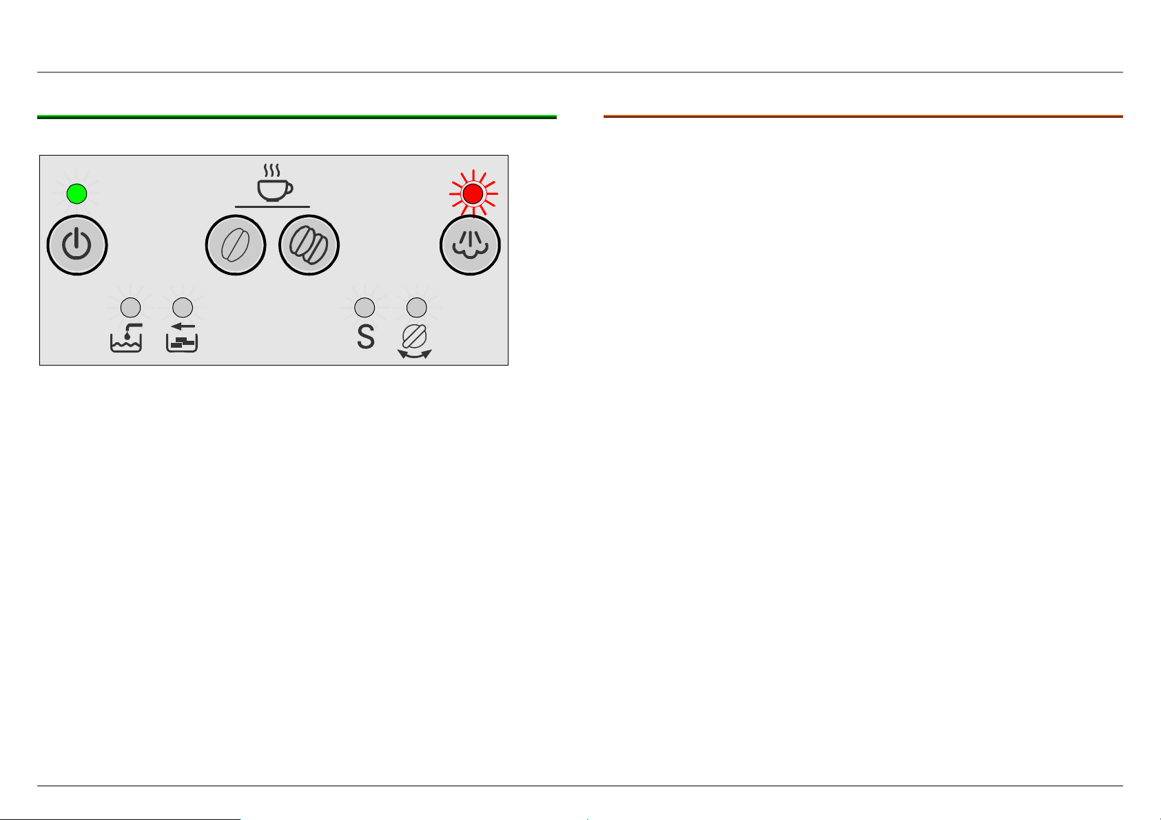
3.3.6 Heating up to steam
Press the “Steam” button
LED button:
LED display:
Appliance:
Standby is lit green, Steam flashes
No display
Heat up to steam temperature
3.3.6.1 Options
Press Standby button: Heating up is stopped, appliance
switches to standby
Press Coffee mild button: Heating up is stopped, appliance
switches to standby
Press Coffee strong button: Heating up is stopped, appliance
switches to standby
Press the “Steam” button: Heating up is stopped, appliance
switches to standby
Open hot water/steam valve: Wait until steam temperature has
been reached, then draw steam
Remove trays: Continues heating, “Trays
missing” LED flashes
Remove water tank: No response
Release brewing unit: Heating up is stopped, Service
LED flashes alternating with
Standby LED buttons (dim red)
Lock brewing unit: Appliance switches to standby
58300000123125_ARA_en_d.doc – 09.10.09 Seite 17 von 78
Page 18
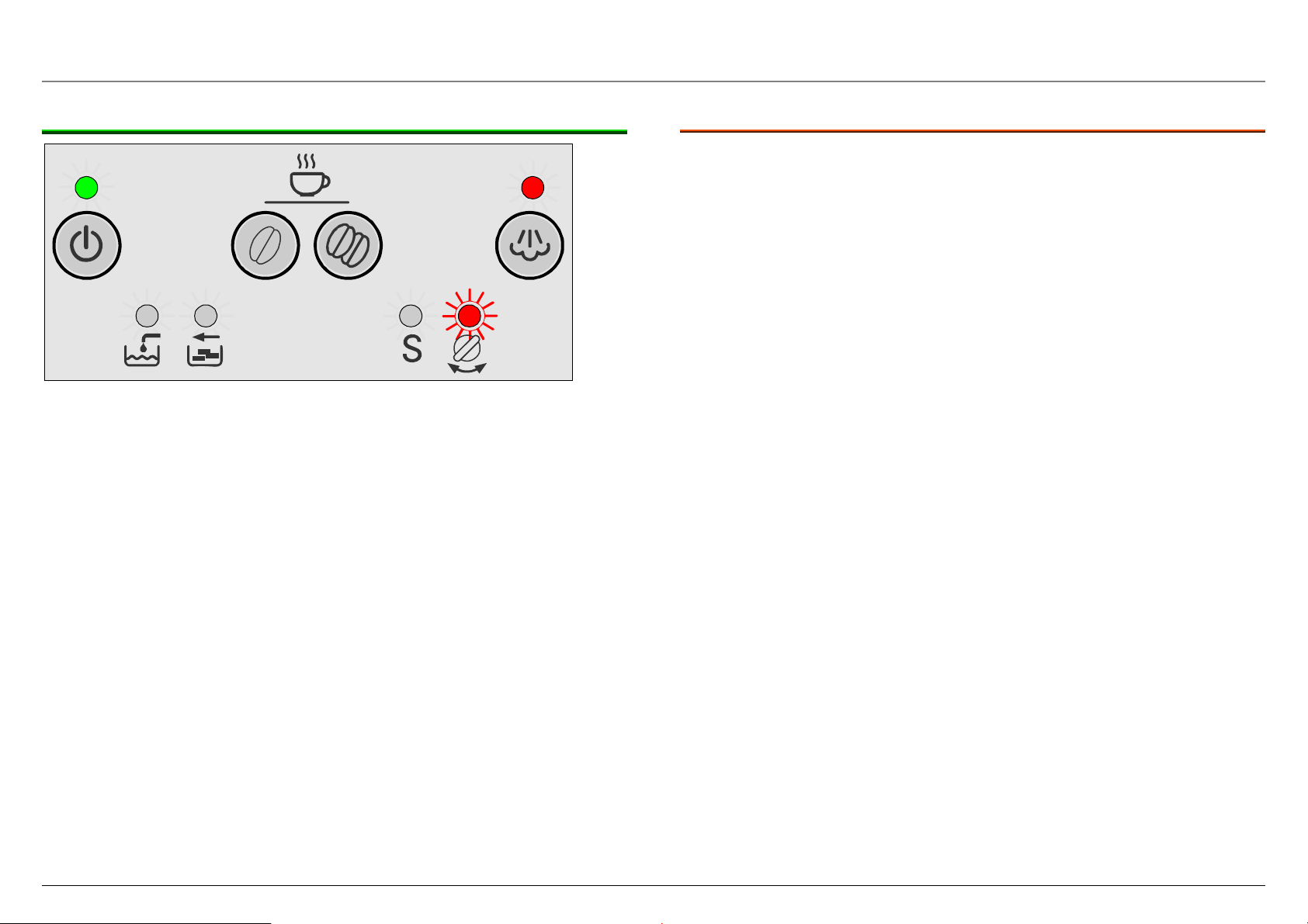
3.3.7 Steam ready
LED button:
LED display:
Appliance:
Standby is lit green, Steam is lit
“Open steam valve” flashes
At steam temperature for approx. 1 minute
3.3.7.1 Options
Press Standby button: Stopped, appliance s witches to
standby
Press Coffee mild button: Stopped, appliance switches to
ready to use
Press Coffee strong button: Stopped, appliance switches to
ready to use
Press the “Steam” button: Stopped, appliance switches to
ready to use
Open hot water/steam valve: Steam is generated, “Close hot
water/steam valve” LED is lit
Close hot water/steam valve is lit Steam ready ends
Remove trays: Steam ready continues for
approx. 1 minute, “Close hot
water/steam valve” and “Trays
missing” LEDs flash
Release brewing unit: Steam ready is stopped, Service
LED flashes alternating with
Standby LED buttons (dim red)
Lock brewing unit: Appliance switches to standby
58300000123125_ARA_en_d.doc – 09.10.09 Seite 18 von 78
Page 19
3.3.8 Drawing steam
Open hot water/steam valve
LED button:
LED display:
Appliance:
Standby flashes green, Steam flashes
Open steam valve is lit
Pump is running, heating on
Convey steam
3.3.8.1 Options
Press Standby button: Stopped, appliance switches to
standby
Press Coffee mild button: Brewing is stopped, “Close hot
water/steam valve” LED is lit
Press Coffee strong button: Brewing is stopped, “Close hot
water/steam valve” LED is lit
Press the “Steam” button: Brewing is stopped, “Close hot
water/steam valve” LED is lit
Close hot water/steam valve is lit Stopped, appliance switches to
ready to use
Remove trays: Brewing is stopped, “Close hot
water/steam valve” LED is lit
Remove water tank: Brewing is stopped after approx.
30 sec., “Add water” and “Close
hot water/steam valve” LEDs are
lit
Release brewing unit: Steam on is stopped, Service
LED flashes alternating with
Standby LED buttons (dim red)
Lock brewing unit: Appliance switches to standby
58300000123125_ARA_en_d.doc – 09.10.09 Seite 19 von 78
Page 20
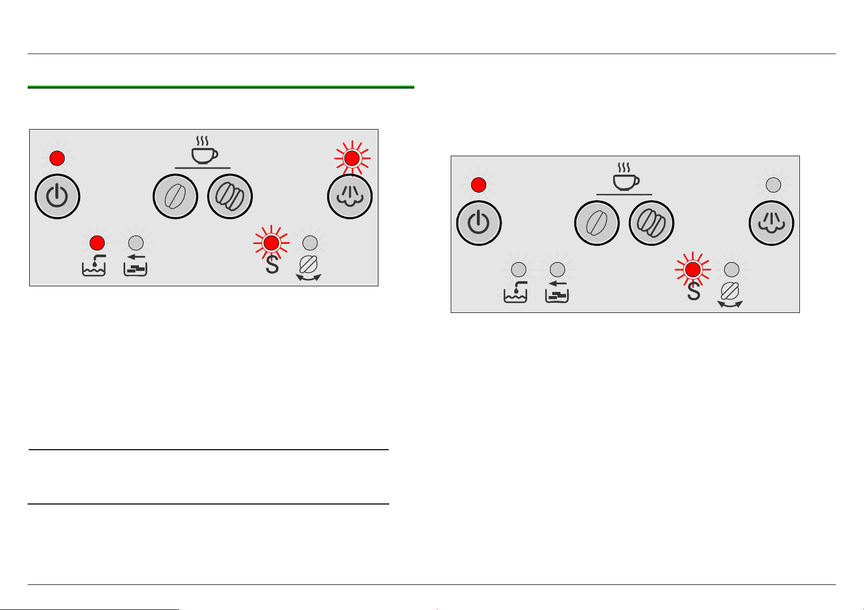
3.4 Adjusting water hardness
It is important that the water hardness is set correctly so that the
appliance indicates in good time when it requires descaling.
Water hardness 4 has been preset
Determine the water hardness with the enclosed test strip or ask your
local water supplier.
5 s
Hardness 4
Hardness 3
► Switch on the appliance with the mains switch.
Appliance is in standby
► Press Steam button for 5 seconds:
Number of lit LEDs indicates the currently set water hardness.
► Keep pressing Steam button until the buttons for the
required water hardness light up.
If no button is pressed within 90 seconds, the appliance switches back
to coffee ready without saving the water hardness. The previously set
water hardness is retained.
► Press Standby button once.
The set LEDs flash 3 times, the selected water hardness is saved.
Note:
If a water filter is used, water hardness 1 must
be set!
Hardness 2
Hardness 1
58300000123125_ARA_en_d.doc – 09.10.09 Seite 20 von 78
Page 21
3.5 Reducing temperature
Temperature reduction by 4°
5 s
► Switch on the appliance with the mains switch.
Appliance is in standby
► Press Coffee strong and Steam buttons for 5 seconds:
Normal temperature: Add water and Trays missing LEDs are lit
► Press Coffee strong button to reduce the temperature
by 4°
–4°: Add water LED is lit
► Press Standby button once
The set LEDs flash 3 times, the selected water hardness is saved.
If no button is pressed within 90 seconds, the appliance switches back
to coffee ready without saving the water hardness. The previously set
water hardness is retained.
Normal
- 4°
3.6 Reset
► Switch on the appliance with the mains switch.
Appliance is in standby
► Remove drip tray
► Press Coffee mild and Coffee strong buttons for 5
The following values are reset to the factory settings:
– Amount of liquid coffee (set to 125 ml)
– Temperature (set to normal)
– Water hardness (set to hardness 4)
All 4 LEDs flash 3 times. Appliance switches back to standby
seconds:
3 x
5 s
58300000123125_ARA_en_d.doc – 09.10.09 Seite 21 von 78
Page 22
3.7 Manually cooling the heater
Heater and parts of the tube system become hot during operation. For
service activities heater and tube system can be cooled down
manually.
► Provide a 0.5 litre collecting vessel
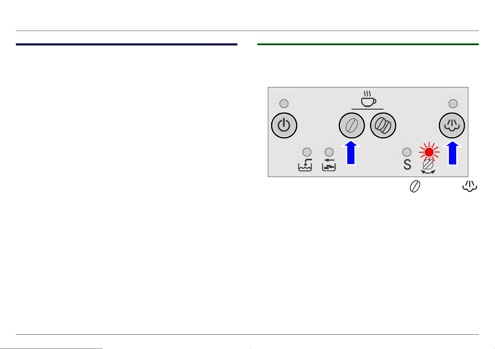
3.7.1 Procedure
► Insert mains plug and set mains switch to “I”
Appliance is in standby. The standby button LED is lit dimly red.
► Place collecting vessel under steam nozzle.
► Simultaneously press coffee on MILD and steam
buttons for 5 seconds.
LED above Open steam tap symbol flashes for 5 seconds.
► Open steam tap: (if the steam tap is not opened during this
time, the appliance switches back to standby).
Cold water (maximum 0.5 litres) is conveyed out of the steam pipe.
It is not reheated, heater is cooled manually.
► Close steam tap.
Pump stops. Appliance switches back to standby. The standby button
LED is lit dimly red.
58300000123125_ARA_en_d.doc – 09.10.09 Seite 22 von 78
Page 23
3.8 Service programme
The service programme combines the descaling and cleaning
process in one cycle.
If S lights up on the display when the appliance is switched on, the
service programme must be started.
Use liquid descaling agent, mat. no. 310451, and detergent tablets,
mat. no. 310575!
Risk of damage!
► Never interrupt the service programme!
► Never descale the appliance with vinegar or vinegar-
based substances.
► Before starting the service programme, remove
WARNING
While the Service programme is running (approx. 40 min.), the S LED
flashes.
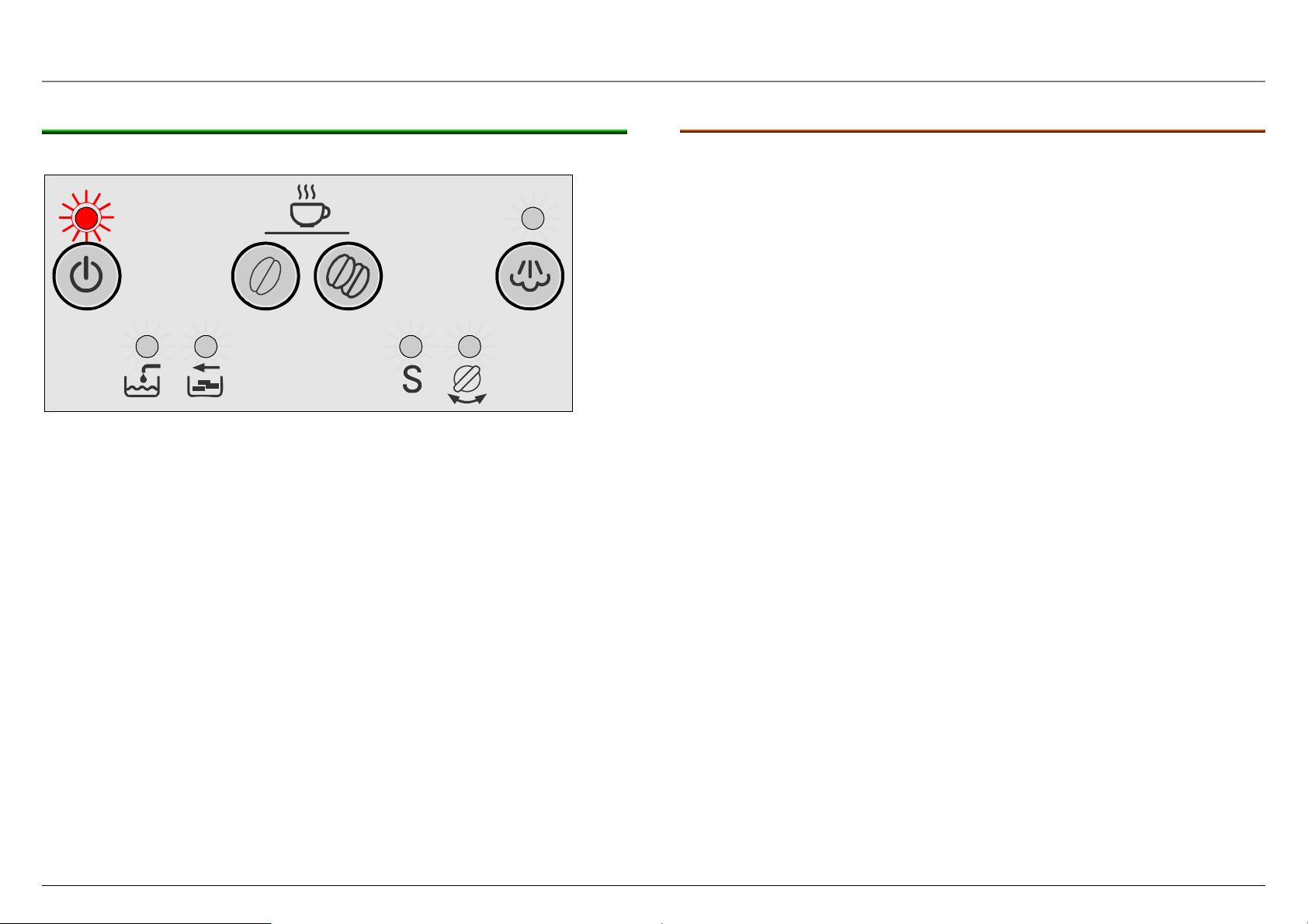
3.8.1 Service alarm
water filter from the water tank!
3.8.2 Starting the service programme
► To start the Service programme, switch the appliance to
standby.
5 S
LED button:
LED display:
Standby is lit dim red
S is lit
► Press Coffee mild button for 5 seconds
The appliance is initialised, heats up and is rinsed.
The Service alarm is displayed after
► 180 coffee brewing processes; irrespective of the coffee
strength and cup size (Cleaning alarm)
or
► 120 l water flow at a water hardness setting of 1
90 l water flow at a water hardness setting of 2
60 l water flow at a water hardness setting of 3
30 l water flow at a water hardness setting of 4
For steam the calculation is as follows: 6.4 seconds of steam
production correspond to 1 dl of hot water production.
58300000123125_ARA_en_d.doc – 09.10.09 Seite 23 von 78
LED button:
LED display:
Standby is lit red
S flashes, Empty trays is lit
Page 24
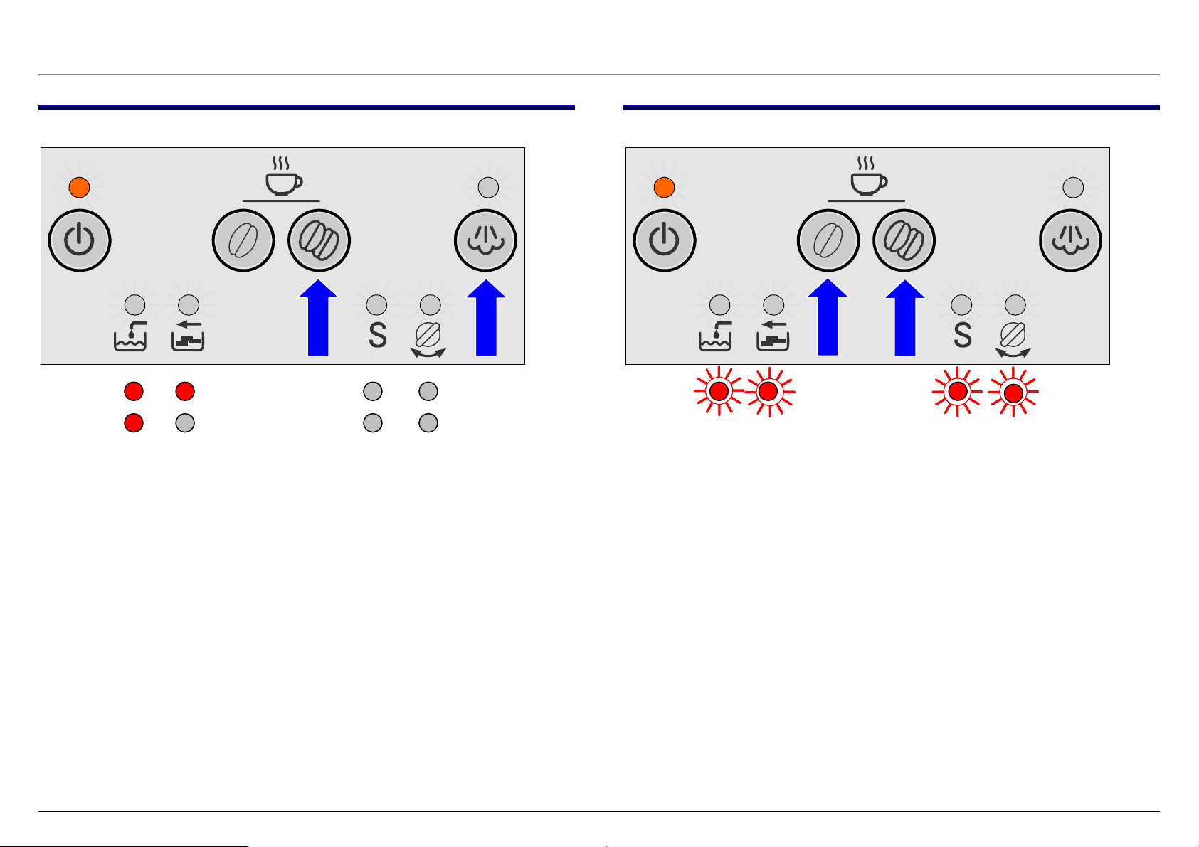
3.8.3 Sequence of the Service programme (descaling)
► Remove drip tray with dregs drawer, empty and re-insert (time
window > 6 seconds).
LED button:
LED display:
Standby is lit red, Fill water is lit
S flashes, Steam flashes
► Place one cleaning tablet in the slot
► Fill water tank with lukewarm water, add descaling agent and
dissolve completely in water (total amount of liquid = 0.5
litres).
or
► Fill water tank with 0.5 l of ready mixed descaling solution.
► Press the steam button
Appliance starts the descaling cycle. Duration approx. 10 minutes.
Service marker is set
LED button:
LED display:
Standby is lit red
S flashes
Liquid outlet via drainage valve: 1 x 60 ml
16 x 15 ml
Total: 300 ml
Descaling via drainage valve ended.
If using descaling tablets, add two tablets.
Observe the dissolving time of the tablets
58300000123125_ARA_en_d.doc – 09.10.09 Seite 24 von 78
(approx. 4–6 minutes)!
Page 25

Sequence of the Service programme (descaling)
LED button:
LED display:
Standby is lit red
S flashes, Turn hot water/steam valve flashes
► Place an adequately large receptacle (approx. 0.5 litres) under
the steam pipe.
► Turn hot water/steam valve to hot water production
Sequence of the Service programme (rinsing)
LED button:
LED display:
Standby is lit red
S flashes, Empty trays is lit
► Remove drip tray with dregs drawer, empty and re-insert
(time window > 6 seconds).
Appliance continues descaling cycle. Duration approx. 5 minutes.
Liquid outlet via steam pipe: 15 x 20 ml
Total: 300 ml
Descaling ended
LED button:
LED display:
Standby is lit red, Steam is lit
S flashes, Fill water is lit
► Empty and clean water tank, fill with fresh water up to the
“max” mark and re-insert.
58300000123125_ARA_en_d.doc – 09.10.09 Seite 25 von 78
Page 26

Sequence of the Service programme (rinsing)
► Place an adequately large receptacle (approx. 0.5 litres) under
the steam pipe.
► Press the “Steam” button.
Appliance starts rinsing. 100 ml of water are conveyed.
LED button:
LED display:
Standby is lit red
S flashes
Rinse cycle via steam pipe has ended when Turn hot water/steam
valve LED is also lit.
LED button:
LED display:
Standby is lit red
S flashes, Turn hot water/steam valve is lit
► Turn hot water/steam valve to O
Appliance starts the cleaning process. 100 ml of water are conveyed
via the drainage valve.
58300000123125_ARA_en_d.doc – 09.10.09 Seite 26 von 78
Page 27

3.8.4 Sequence of the Service programme (cleaning)
Brewing module is moved to brewing position (drainage position)
LED button:
LED display:
Standby is lit red
S flashes
Liquid outlet via drainage valve: 1 x 80 ml
8 x 15 ml
Total: 200 ml
Brewing module is moved back to the home position, then to the
brewing position again
Liquid outlet via coffee outlet: 6 x 20 ml
Total: 120 ml
Cleaning cycle has ended when the Empty trays LED flashes
► Remove drip tray with dregs drawer, empty and re-insert (time
window > 6 seconds).
3.8.4.1 Manual rinsing after interruption If the Service programme was interrupted, e.g. by a
power failure, always rinse the appliance before
switching it on again.
► Press Standby button
LED button:
Standby and Steam flash
► Rinse water tank and fill with fresh water
► Press the “Steam” button
Appliance is rinsed via drainage valve
LED display:
Turn hot water/steam valve flashes
► Place cup under steam pipe, open hot water/steam valve
Appliance is rinsed via hot water/steam valve.
LED display:
Turn hot water/steam valve is lit
Service marker is deleted
Appliance heats up and is ready for use again when the Standby LED
is lit green.
► Turn hot water/steam valve to O
Service marker is deleted
Appliance is rinsed and is ready for use again.
58300000123125_ARA_en_d.doc – 09.10.09 Seite 27 von 78
Page 28

3.9 Maintenance and daily cleaning
Risk of electric shock!
► Unplug the appliance before cleaning it.
► Never immerse the appliance in water.
► Do not use a steam cleaner.
Risk of damage!
► Do not use scouring agents.
3.9.1 Daily cleaning
► Wipe the outside of the appliance with a damp cloth. Do not
use scouring agents.
► Rinse out the water tank with water only.
► Remove, empty and clean the trays for residual water (21)
and coffee grounds (20).
Wash all removable parts by hand only.
► Wipe out or vacuum the inside of the appliance (tray holders)
Note!
If the appliance is cold when switched on with the
standby-button, or if it is set to standby after brewing
coffee, it is automatically rinsed, i.e. the system cleans
itself.
58300000123125_ARA_en_d.doc – 09.10.09 Seite 28 von 78
Page 29

3.9.2 Cleaning the brewing unit
The brewing unit can be removed for cleaning.
► Turn off the appliance with the standby-button.
► Turn the mains switch to off.
► Open the service flap on the right hand side of the appliance.
► Press and hold the red button (1) down and push the handle
up until you hear it engage.
► Grasp the brewing unit by the handle.
► Rinse the brewing unit under running hot water. Do not use
cleaning agents.
Risk of damage!
Do not place the brewing unit in the dishwasher!
► Vacuum the inside of the appliance or clean it with damp
cloth.
► Dry and reinsert the brewing unit all the way into the
appliance.
► Press and hold the red button (1) down and push the handle
down until you hear it engage. The brewing unit is now
secure.
► Reinsert and close the service flap.
If the appliance is cold when switched on again is automatically
rinsed, i.e. the system cleans itself.
58300000123125_ARA_en_d.doc – 09.10.09 Seite 29 von 78
Page 30

4 COMPONENTS
4.1 Flowmeter
The composition of the coffee
mixture is a well guarded secret of
the coffee roasting
establishments. To ensure that an
excellent coffee can be produced
from this secret, the coffee beans
must be roasted carefully and the
coffee machine controlled
precisely – unless the dosage is
constant, the quality of the coffee
cannot be maintained.
The flowmeter (A) is installed on the suction side between the water
tank (B) and pump (C). To ensure a precise measurement result, the
flowmeter must be operated in a horizontal position.
4.1.1 Design and function
Water is pumped in from the water
tank and flows through the
flowmeter.
Water is supplied via the
connection pipe in the lower
section of the housing (D).
Water is discharged via the
connection pipe in the upper
section of the housing (A).
The two halves of the housing are
sealed with a silicone seal (B).
The fan impeller (C) with the two
attached magnets is rotated by the
water flow.
The Hall-IC in the upper section of
the housing (A) generates square
pulses which measure the actually
required amount of water.
When installing the flowmeter, ensure that the
direction of flow is correct. An arrow on the
flowmeter housing indicates the direction of flow.
58300000123125_ARA_en_d.doc – 09.10.09 Seite 30 von 78
Page 31

4.1.2 Connection diagram
The flowmeter itself does not supply an output voltage but simply
switches the signal connection to 0 volt earth (actuated) or leaves it
open (unactuated). Square pulses are generated in the upper
section of the housing via the Hall-IC.
Wrong connection of + voltage, signal and earth destroys the
flowmeter.
4.2 Heater and NTC-sensor
4.2.1 Heater (Instantaneous water heater)
In the instantaneous water heater the water for coffee production or
hot water/steam purchase is heated up.
Prevent inductive faults via the cable!
Do not lay the cable together with supply cables to
consumers.
Therefore the water is pumped in a stainless-steel pipe (A), which is
cast in together with a heating resistor (B) in an aluminum block.
58300000123125_ARA_en_d.doc – 09.10.09 Seite 31 von 78
Page 32

4.2.2 Characteristic of NTC-sensor
Temperature R min R nom R max
25 °C 93.801k
100k
106.199k
95 °C 6.414k 6.624k 6.834k
140 °C 1.696k 1.771k 1.845k
58300000123125_ARA_en_d.doc – 09.10.09 Seite 32 von 78
Page 33

4.3 Brewing unit
The brewing unit forms the central element in the espresso machine.
The brewing unit extracts the aroma, flavour and bitter agents from the
ground coffee and forms the crema.
4.3.1 Operating principle
Ground coffee pours through the filling shaft (2) into the brewing
chamber and is compressed. Hot water is introduced under pressure
via the water supply (4) and forced through the ground coffee. The
coffee which is produced is conveyed to the coffee outlet (10). To
optimise crema formation, the crema valve, which is situated above
the brewing head, opens when the pressure reaches 4.5 bar.
At the end of the brewing process the used coffee dregs are emptied
into the dregs drawer via the discharge chute (7).
4.3.1.1 Variable brewing chamber
The brewing unit consists primarily of the brewing chamber (A), into
which the ground coffee (7 g – 14 g) is metered, and the springmounted brewing head (B) which moves upwards to seal the brewing
chamber.
Control lever, filling amount
1
Filling shaft
2
Locking lever
3
Water inlet
4
Clutch, drive shaft
5
58300000123125_ARA_en_d.doc – 09.10.09 Seite 33 von 78
Catch
6
Discharge chute
7
Stripping handle
8
Brewing head
9
Coffee outlet
10
The ground coffee is compacted and compressed in the brewing
chamber. When hot water is pumped into the brewing chamber, the
rising water pressure pushes up the brewing head, increasing the
volume in the brewing chamber. This improves extraction of the
flavours and formation of the crema.
Page 34

4.3.2 Sequence of the brewing cycle
4.3.2.1 Grinding and metering
4.3.2.2 Compression
Coffee beans are ground in the grinding unit (A). The ground coffee is
conveyed into the open brewing chamber via the funnel (B). The
amount of ground coffee generated depends on the running time of
the grinding unit. The brewing unit can process from 7 g to 14 g of
ground coffee.
Alternatively ground coffee can be poured in via the powder slot.
The grinding unit stops. The gears control the brewing unit to the
upper end position. In doing so, the ground coffee is compressed in
the brewing chamber (C). The pressure applied to the ground coffee
causes the spring-mounted brewing head (D) to move up. The more
powder there is in the brewing chamber, the higher the brewing head
is pushed upwards during compression. The actual amount of powder
is measured by a slide which is connected mechanically to the
brewing head and, if required, corrects the amount during the next
brewing process.
58300000123125_ARA_en_d.doc – 09.10.09 Seite 34 von 78
Page 35

4.3.2.3 Brewing
4.3.2.4 Emptying
The brewing process starts. The pressure pump conveys the water
into the brewing unit. The brewing head (D) is moved up by the water
pressure, thereby increasing the volume in the brewing chamber. The
hot water is mixed with the ground coffee longer and more intensively,
thereby improving extraction of the flavours and formation of the
crema. If the pressure inside the brewing chamber increases above
When the programmed amount of water is reached, the pump stops.
The pressure in the brewing chamber drops and the coffee dregs are
compressed into a solid cake. The drainage valve opens, pressure
and residual water are released into the drip tray. When the brewing
unit descends, the brewing chamber moves back to the initial position
(G) and the coffee dregs are emptied into the dregs drawer.
4.5 bar, the crema valve (E) opens and the coffee can flow to the
coffee outlet (F).
58300000123125_ARA_en_d.doc – 09.10.09 Seite 35 von 78
Page 36

4.3.3 Removing the brewing unit
The brewing unit is accessed by opening the service flap on the righthand side of the appliance. Once released, the brewing unit can be
taken out of the appliance for cleaning.
4.3.3.1 Basic position
The brewing unit can only be replaced in the basic position.
► The brewing chamber is located completely underneath the
filling funnel.
► The unlocking lever is engaged in the "locking mechanism
open" position (1).
► The mark on the input shaft is next to the tip of the marking
arrow (2).
4.3.3.2 Locking mechanism
When locked, the brewing chamber is prevented from moving. Only
when placed in the appliance is the locking mechanism released by
two cams (1) in the brewing unit compartment. Lock bolt (2) releases
unlocking lever (3). The unlocking lever is released by pressing knob
(4). The unlocking lever can be turned downwards, where it engages
in recess (5). The brewing unit is locked. A microswitch on the
transmission housing monitors the locked status.
58300000123125_ARA_en_d.doc – 09.10.09 Seite 36 von 78
Page 37

4.3.4 Compensation of the grinding unit running time
The amount of ground coffee which is generated by the grinding unit
depends on the running time of the grinding unit.
To ensure that the required amount of coffee is always ground, both
with different types of coffee, at different grinding settings and possibly
with worn grinding tools, the amount of ground coffee which was
actually conveyed to the brewing module (B) is measured.
The electronics module measures the number of the voltage changes
(connection A) caused by the switching processes which occur
immediately before the pressure pump switches on and can therefore
detect whether and how much ground coffee has been metered. This
value can be compared with the nominal value for the aroma setting.
Differences are adjusted by changing the running times of the grinding
unit.
The more powder there is in the brewing chamber, the higher the
spring-mounted brewing head is pushed upwards during compression.
A microswitch (µ) closes and opens as it moves past via a slide which
is connected mechanically to the brewing head.
4.3.4.1 Switching states
If there is a minimum amount of coffee (<7 g), the brewing head
does not move. The switch is not actuated. = Not enough coffee
beans. ADD BEANS is displayed
(I)
(II)
(III)
(IV)
Special cases:
Too hot and too little
powder before brewing
Too little powder during 1st
brewing process
Amount of powder >7 g – <10 g
Amount of powder 10 g
Amount of powder >10 g – <13 g
Amount of powder >14 g = Too many coffee beans. The
running time of the grinding unit must be reduced.
Brewing is ended (dry discharge),
there is no pumping. The brewing
module moves to the grinding
position. Auto cooling starts (several
ml of water are conveyed) and
SYSTEM TOO HOT is displayed
ADD BEANS is displayed and an
additional time of 1.3 sec. is given.
Compensation is not active during
this and the next brewing process.
58300000123125_ARA_en_d.doc – 09.10.09 Seite 37 von 78
Page 38

4.4 Gear unit
The gear unit is the drive for the brewing unit.
The gear motor is actuated at +/– 16 V DC and transfers its power via
gears to a drive shaft which is connected to the brewing unit.
4.4.1 Front housing
Microswitches (S1 and S2) are attached to the front housing of the
gear unit. These microswitches measure the position of the gears and
the brewing unit via a cam (B) connected to the drive shaft.
4.4.2 Rear housing
On the rear housing section of the gear unit the drainage valve (B) is
attached to the expansion chamber (C). This valve controls the
passage of water from and to the brewing unit. The microswitch (D) is
actuated by the lock on the brewing unit. The drive shaft (E) is the
connection to the brewing unit.
58300000123125_ARA_en_d.doc – 09.10.09 Seite 38 von 78
Page 39

4.4.3 Cam on the gear unit
The position of the brewing unit is detected with two microswitches S1
and S2. These two switches are able to define three positions.
When the appliance is switched on, the switch status of the
microswitches is checked and transmitted to the control module. The
brewing unit is moved to the basic position (= initialising).
Home position
Brewing position Drainage position
The brewing unit
is in the grinding
position and can
be filled.
Switch S1 is
activated by
switch cam (A).
Switch S2
remains open.
The transmission
turns clockwise
until switch S2 is
closed by switch
cam (A) and
switch S1 is open.
The brewing unit
is in the brew
position. The
transmission
motor stops.
Water can be
supplied and
coffee can be
brewed.
Once the brewing
process is complete,
the system is
drained.
For this, the motor
turns the cam disc
back by about 8°, so
that the drainage
valve is opened
again and the
remaining water can
run into the drip tray.
Switches S1 and S2
are closed.
S1 ON
S2 OFF
58300000123125_ARA_en_d.doc – 09.10.09 Seite 39 von 78
S1 OFF
S2 ON
S1 ON
S2 ON
Page 40

4.4.4 Drainage valve
The drainage valve (B) connects the water inlet (A) to the brewing unit
and drains the system at the end of the brewing cycle.
4.4.4.1 Home position
When the gears are in the home position, the drainage valve is open.
The cam (E) of the actuator must then be in the illustrated position.
Warning!
Malfunction
The position of the actuator and therefore the cam (E)
is not specified permanently on the drive shaft.
The actuator may be in the wrong position. The
function sequence may malfunction.
When installing the gears, ensure that actuator is
in the correct position, as indicated under “Home
position”!
58300000123125_ARA_en_d.doc – 09.10.09 Seite 40 von 78
Page 41

4.4.4.2 Brewing position
When the gears move into the brewing position, the drive shaft rotates
with the actuator (D) in an anti-clockwise direction.
4.4.4.3 Drainage position
Once the brewing process is complete, the water pump switches off.
The brewing unit is moved upwards. The connection to the drainage
valve is closed with the water
coupling in the brewing unit. The switch cam on tripping device (D)
reaches into the drainage valve control line and closes it. Water can
flow from inlet (A) through drainage valve (B) to outlet (C).
The transmission motor turns the input shaft with tripping device (D)
back through about 8° and opens the drainage valve.
The pressure is relieved and the water can drain into the expansion
chamber and then into the drip tray. To prevent underpressure, air can
flow back through valve (B).
Then the transmission turns back in a clockwise direction until it is in
the basic position again.
58300000123125_ARA_en_d.doc – 09.10.09 Seite 41 von 78
Page 42

4.5 Steam valve and proximity switch
In order for hot water or steam to be dispensed, steam valve (1) must
be turned open.
The pump must not start supplying until the steam valve is open.
For this, there is a lever with a magnet (2) on the steam valve which is
guided by reed switch (3) in the control board when opening.
Hot water or steam is guided into the steam valve via pressure hose
(4) and then on to steam pipe (5).
To dispense steam, first press the steam button and wait for the
heat up phase.
Dispense coffee
Dispense
Steam
Hot water
58300000123125_ARA_en_d.doc – 09.10.09 Seite 42 von 78
Page 43

4.6 Hot water / steam nozzle
Risk of burns!
The nozzle gets very hot.
► Do not touch the metal parts!
DANGER
(1) Sleeve with plastic grip
To dispense hot water or to froth
milk, move the sleeve downward
by the plastic grip.
To warm drinks with steam, slide
the sleeve upwards by the plastic
grip.
(2) Tip of nozzle with inlet
Sucks in milk and mixes with air
to make milk froth.
Note:
Every time you froth milk, clean the nozzle immediately
afterwards by dispensing hot water. Dried on milk
residues are difficult to remove.
4.6.1 Function
The steam flows through steam pipe
(A) and the connected steam nozzle,
thereby creating underpressure
inside the steam nozzle.
This underpressure is balanced out
by fresh air flowing in through
opening (B) on the nozzle holder
and (C) on the tip of the nozzle.
If the nozzle is immersed in cold milk
to above side opening (C) and steam
is dispensed, fresh air flows in
through opening (B) on the nozzle
holder. At the same time, milk is
sucked into this air flow through
opening (C), mixed with the flow of
steam and emitted at the tip of the
steam nozzle.
The resulting circulation of sucked
in, mixed and emitted milk, warms
the milk up. The milk froth is created
by the mixing of the milk proteins
with air. The proteins are stable up
to approximately 76 °C.
They are destroyed by higher
temperatures and froth formation is
not possible then.
58300000123125_ARA_en_d.doc – 09.10.09 Seite 43 von 78
Page 44

4.7 Water filter
The filter cartridge is screwed directly into the water tank. The filter
cartridges can be used for all appliances belonging to this series.
Carbon hardness, contents (e.g. chlorine) which impair taste and
odour, heavy metals and other substances are reduced to protect the
machine. Important minerals and fluoride are retained.
4.7.1 Filtration when drawing water
The water required for the preparation of coffee is filtered directly
before use. The water is drawn in by fins in the lower area of the filter
cartridge, filtered by the granulate and conveyed out through the
centre of the water tank valve. (= Up flow principle)
4.7.2 Filter specifications
The filter capacity at 27° dH is approx. 50 litres (400 brews) or
2 months.
The filter filling consists of approx. 100 ml ion exchange resin and
silvered activated carbon in the ratio 4:1.
Filter diameter:
27–42 mm
Filter length:
Filling volume:
Filter effect:
(Reduction if
following
substances
are in the
water)
175 mm
95–100 ml
Carbon
hardness
Chlorine
Lead
Copper
Aluminium
up to
up to
up to
up to
up to
► Follow the information in the operating
instructions for inserting or replacing the water
filter!
► Do not insert filter if the descaling display lights
up! First descale the appliance!
► If the appliance is always operated with the
water filter inserted, descale as a precaution
once or twice a year!
58300000123125_ARA_en_d.doc – 09.10.09 Seite 44 von 78
Page 45

5 FUNCTIONS
5.1 Construction
5.1.1 Overview, left side
1
2
3
4
5
6
7
8
9
10
11
Pump with temperature monitoring and angle
for flow reduction
Transmission position microswitch
Transmission position microswitch
Flow meter
Transformer
Electronic main board
Mains switch
Control panel
Steam valve
Grinding compensation microswitch
Pressure valve 4 bar
12
13
14
15
NTC
Heating element
Transmission cam disc
Grinder with temperature sensor
58300000123125_ARA_en_d.doc – 09.10.09 Seite 45 von 78
Page 46

5.1.2 Overview, right side
Once the brewing unit has been removed, the following components
are visible:
Centring for the brewing unit Part of the component
1
bracket
Input shaft for the brewing unit Part of the transmission
2
unit
Cams for releasing the brewing unit Part of the component
3
bracket
Coupling for coffee outlet Screwed to the
4
component bracket
Switch for grinder compensation Screwed to the
5
component bracket
Brewing unit inserted switch On transmission
6
housing
Filling duct Screwed to grinder
7
58300000123125_ARA_en_d.doc – 09.10.09 Seite 46 von 78
Page 47

5.2 Fluid system
The pump (c) sucks the water out of the water tank (a)
via flow meter (b). The water flows through the flow
meter thereby causing the impeller inside to rotate. This
generates electrical pulses which are used to determine
the actual volume of water required.
The pump generates a pressure of 5 - 8 bar. The water
is conveyed through a reduction angle and pressure
hose to the heating element. The NTC (e) records the
temperature at the outlet of the heating element.
After the heating element, the fluid system is divided into
a pressure line to steam valve (g) and a pressure line to
valve (f) and then to the brewing unit. Valve (f) has an
opening pressure of 4 bar and closes off the brewing
system when hot water/steam is being dispensed.
At the end of a brewing cycle, the remaining water is
drained from the brewing unit into the drip tray via
drainage valve (h). The rest of the system remains full
of water.
Warning:
The appliance must be emptied if there
is a risk of frost (e.g. on the way to or
from customer services). The heater or
the piping may be damaged if the water
in the fluid system freezes.
Emptying the fluid system: see
appliance test
58300000123125_ARA_en_d.doc – 09.10.09 Seite 47 von 78
Page 48

5.3 Temperature
5.3.1 Temperature pattern
The temperature graph indicates the temperature pattern on the
heater during operation.
! After coffee has been drawn,
the appliance may be briefly
disabled from re-heating.
As soon as steam has been
drawn, coffee can be brewed
again without waiting for the
appliance to cool down.
Coffee cannot be drawn after
steam has been drawn if there
is too little ground coffee in the
brewing unit. The brewing
process is terminated, there is
no pumping. The brewing unit
moves to the grinding
position.
I
II
III
IV
V
VI
VII
VIII
IX
58300000123125_ARA_en_d.doc – 09.10.09 Seite 48 von 78
Heating up
Ready to use
Draw coffee (91 °C) / draw hot water (95 °C)
Re-heating
Ready to use
Heating up to draw steam (140 °C)
Steam ready
Drawing steam
Cooling down after drawing steam
A
B
C
D
E
F
Switch on, press Standby button. Heating up process begins
Press coffee dispensing button or draw hot water
Stop drawing coffee / hot water
Press steam button, heating up process begins
Open steam valve for steam production.
Close steam valve to stop steam production, cooling down
process begins
Page 49

6 REPAIR
6.1 Replacing the brewing unit
6.1.1 Removing the brewing unit
The brewing unit is not permanently installed in the appliance and can
be removed once it has been unlocked.
The service flap on the right-hand side of the appliance give access to
the brewing unit.
6.1.1.1 Opening the service flap
The service flap is clipped into the right-hand side of the appliance.
To open:
► Reach into the upper recessed handle and
► pull the service flap outwards.
6.1.1.2 Removing the brewing unit:
1. Press the red knob on the handle and
2. Turn the handle clockwise until you hear it engage.
► Pull the brewing unit out of the guide by the handle.
Symbols on the brewing unit indicate whether the lock is open or
closed.
Lock closed Lock open
58300000123125_ARA_en_d.doc – 09.10.09 Seite 49 von 78
Page 50

6.1.2 Installation of the brewing unit
6.1.2.1 Basic position
The brewing unit can only be inserted in basic position.
► The brewing chamber is totally located underneath the filling
duct.
► Handle is engaged in position „Lock open“ (1).
► Mark on the drive shaft is opposite the peak of the marking
arrow (2).
6.1.2.2 Inserting the brewing unit
Slide the brewing unit into the appliance in the basic position and lock
in place:
1. Press the red knob on the handle and
2. Turn the handle anti-clockwise until you hear it engage.
► First insert the service flap into the lower guide and then press
it in at the top.
Symbols on the brewing unit indicate whether the lock is open or
closed.
Lock closed Lock open
58300000123125_ARA_en_d.doc – 09.10.09 Seite 50 von 78
Page 51

6.1.3 Greasing the brewing unit
During a service, the O-ring for the coffee outlet (A), the lip seal
surrounding the brewing head (B), the O-ring for the water inlet (C)
and the coupling for the input shaft (D) must be thinly greased with
food-safe special lubricating grease PARALIQ® GTE 703 Mat.-no.:
31 0574.
Note:
After replacing the O-ring for the coffee outlet (A) or for
the water inlet (C) they must be thinly greased with foodsafe special lubricating grease PARALIQ® GTE 703
Mat.-no.: 31 0574.
58300000123125_ARA_en_d.doc – 09.10.09 Seite 51 von 78
Page 52

6.2 General disassembly
Risk of electric shock!
Pull out mains plug before disassembly.
Appliance must not be live!
DANGER!
Tools:
► Torx screwdriver T10
► Slotted screwdriver
6.2.1 Preparation
1.
2.
3.
Remove water tank, drip tray with drip plate and dregs
drawer.
Open service flap on the right side of the appliance and
remove.
Release and remove brewing module.
58300000123125_ARA_en_d.doc – 09.10.09 Seite 52 von 78
Page 53

6.2.2 Opening the housing – step 1
1.
2.
3.
4.
Loosen two Torx T10 screws on the cup shelf.
Loosen three Torx T10 screws on the rear panels.
Carefully press in the three locking hooks with a flat screw-
driver and loosen upper housing section.
Lift off upper housing section; disengage on front panel
remove upwards.
58300000123125_ARA_en_d.doc – 09.10.09 Seite 53 von 78
Page 54

6.2.3 Opening the housing – step 2
1.
Loosen two (6) Torx T10 screws on the left (7) and right (8)
sides of the housing.
2.
Pull the left (7) and right (8) sides of the housing to the rear,
disengage from the guides of the base group and remove. If
required, disengage mains switch (9) or remove supply hose
(10) from the flow meter.
3.
Assemble in reverse sequence
58300000123125_ARA_en_d.doc – 09.10.09 Seite 54 von 78
Page 55
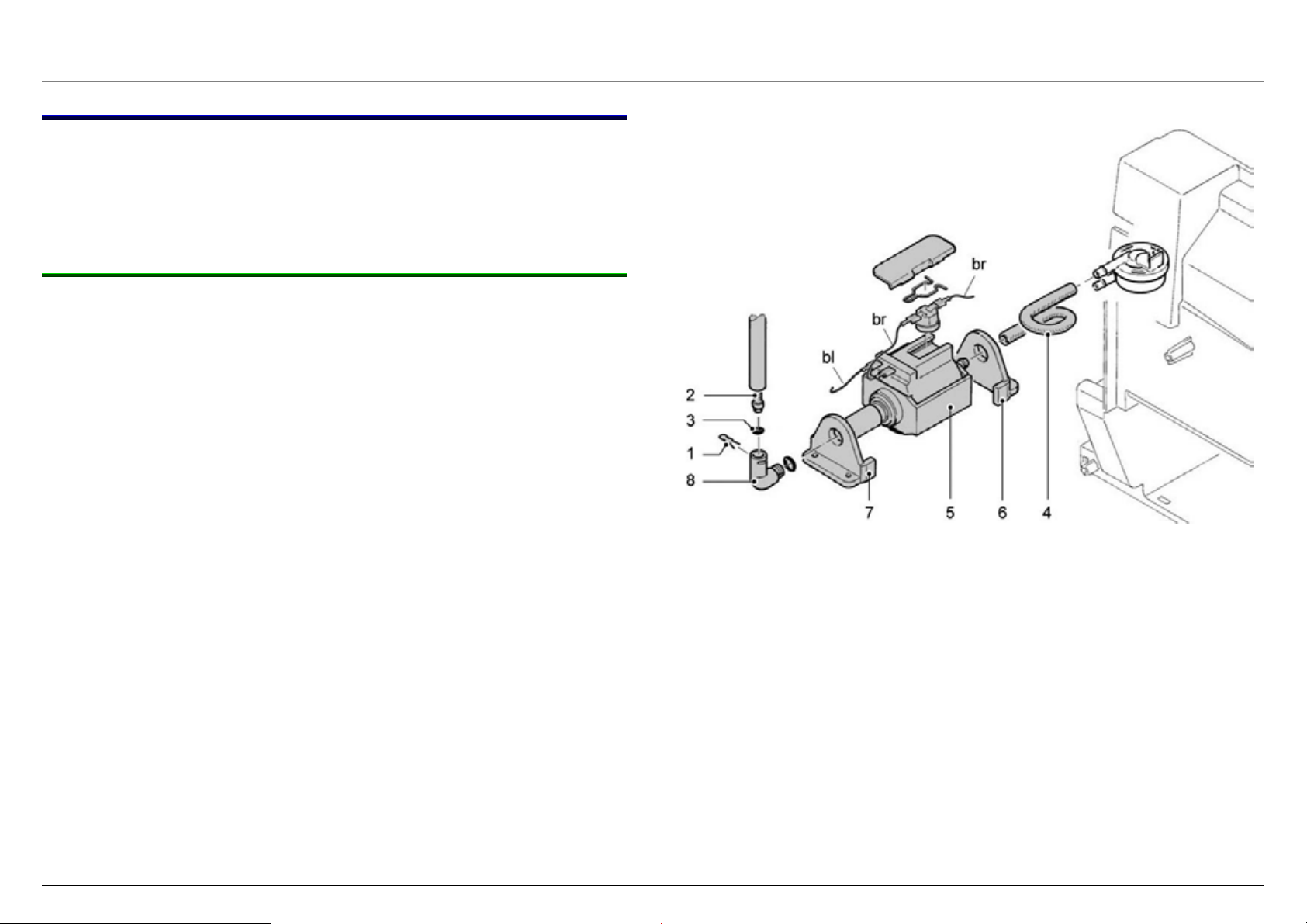
6.3 Replacing the pump
Tools:
► Pliers
► Slotted screwdriver
6.3.1 Procedure:
1.
2.
3.
4.
5.
6.
7.
Disassemble the appliance as described in the "General
disassembly" section.
Remove the retaining clip (1), hose (2) and O-ring (3).
Remove inlet hose (4) from the pump.
First, pull the pump (5) out of the rubber holder (6) on the side
of the inlet hose.
Release the angled hose mount fitting (8) from the pump and
pull the pump out of the second rubber holder (7).
Unplug electrical connections from the pump.
Replace the faulty pump.
8.
To reassemble, proceed in the reverse order of disassembly.
Note the pin assignment of the pump in the wiring diagram.
The O-ring must be replaced with a new one every
time a fluid connection is opened!
58300000123125_ARA_en_d.doc – 09.10.09 Seite 55 von 78
Page 56

6.4 Replacing the thermal fuse
The thermo cut off element (TCO) is a safety element
which is used to prevent damage caused by the heater
overheating. To ensure correct function, it is essential to
install the thermal fuse properly.
► Whenever the appliance is repaired, check as a
precaution that the thermal fuse is in perfect
condition and is correctly installed!
6.4.1 Checking an installed thermo cut off element: The following points must be checked:
► Position and attachment of Teflon hose (must be firmly
anchored)
► Position of thermo cut off element (centred under installation
bracket)
► Quality of the cable connections
► Bend correct
6.4.3 Installation location 1 Screw with circlip
2 Installation bracket
3 Heater
► Installation bracket is firmly attached
6.4.2 Component
The thermo cut off element is supplied as a pre-assembled
component. (Wire colour and type may deviate in reality).
58300000123125_ARA_en_d.doc – 09.10.09 Seite 56 von 78
Page 57

6.4.4 Generally
The thermo cut off (TCO) element is a safety element, which will
protect the appliance and its surrounding against serious damaging
based on an overheating of the heater.
If a thermo cut off element will be defect, please take special care
during the repair to eliminate also the root cause of the overheating.
The assembling and exchange of the thermo cut off element must be
done accordingly to the following instructions.
6.4.5 How to proceed in repair case
The following listed parts of the heater must be exchanged in any
case before the failure analysis will be continued:
► Both thermo cut off elements (complete with wires)
► Temperature sensor (NTC)
► Plastic fluid connectors (including seal ring) at heater inlet and
outlet
The heater itself must not be exchanged in any case. But you have to
ensure, that the heating element will not be damaged.
The control of the heating element must be done by measuring the
power consumption during operation. The respective rated values of
the power consumption and voltage must be taken from the
declaration on the heater itself.
Heater will become hot during measurement!
► Never touch the heater during measurement!
► Cool down the heater manually before repair!
DANGER
The measured power consumption must be within a tolerance of +/5% to the nominal power consumption (measured at nominal voltage).
Maximum acceptable temperature of 300°C on heating element must
not be exceeded during measurement!
58300000123125_ARA_en_d.doc – 09.10.09 Seite 57 von 78
Page 58

6.4.6 Installing / replacing the thermal fuse:
7. Insert installation bracket into the designated guide. (Ensure
that the bracket is inserted according to the picture)
► After removing the defective thermal fuse,
comply with the following new steps to ensure
correct installation:
1. Check installation position for heater (no dirt or projecting
edges permitted).
2. Check installation bracket (no dirt or sharp edges permitted).
3. Check whether it is the correct type of thermal fuse (according
to wiring / circuit diagram).
4. Position Teflon hose over the thermal fuse, ensuring that none
of the electrically conductive parts remains uncovered (same
as the illustrated example of the thermal fuse, slight kinking is
used to fix the hose).
5. Before installation, bend connections of the new thermal fuse
according to the thermal fuse to be replaced. This must be
done with a suitable pair of flat nose pliers. In doing so,
comply with the following points:
► Bend must be at least 5 mm from the housing of the thermal
fuse.
8. Attach installation bracket with the corresponding screw and
circlip.
9. Following installation, check that the installation bracket on the
side of the thermal fuse is not situated on the heater
(according to following picture).
10. Connect thermal fuse wires to the correct terminals in the
appliance.
► Teflon hose and thermal fuse must not be damaged.
► Connections may be bent 1 x only.
6. Position thermal fuse on the mounting surface of the heater,
ensuring that the installation bracket is in the centre of the
thermal fuse housing (attention: note original position).
Important!
Installation bracket must not be situated on the
heater
58300000123125_ARA_en_d.doc – 09.10.09 Seite 58 von 78
Page 59

6.5 Replacing the heating element and NTC sensor
Tools:
► Open-ended wrench WAF 8 mm
► Torx screwdriver T20
► Allen key WAF 4 mm
6.5.1 Procedure:
Note: Heating element may still be hot. Cool the heating
element manually!
1.
2.
3.
4.
5.
6.
7.
Disassemble the appliance as described in the "General
disassembly" section.
Undo Torx T20 screw (4) and remove the earthed conductor
connection from the heating element.
Undo two screws (5), remove thermal fuses (6) and retaining
clips (7) from the heating element.
Undo screws M6 x 25 (2) and pull the heating element out of
the retainer.
Remove the electrical connections from the heating element.
Remove the retaining clip (10) and hose connections (11) and
(12) from the heating element.
Disconnect the NTC plug from the electronic circuit board.
Only lightly tighten NTC temperature sensor until the
spring washer is flat.
O-rings must be replaced with a new one every time a
fluid connection is opened.
8.
Unscrew the NTC sensor (8) from the heating element and
replace it if necessary.
9.
10.
58300000123125_ARA_en_d.doc – 09.10.09 Seite 59 von 78
Replace the faulty heating element.
To reassemble, proceed in the reverse order of disassembly.
Page 60

6.6 Replacing the electronics board
Tools:
► Torx screwdriver T10
► Long-nosed pliers
Risk of damage!
Static voltage may destroy components on the
electronics module!
WARNING
Procedure:
Disassemble appliance as described in the chapter “General
1.
disassembly”, Steps 1 and 2.
Place earthing strap around your wrist and connect to the earth
2.
cable of the unplugged machine! This will prevent a potential
difference.
► Use earthing strap!
Loosen fastening screws (1), Torx T10. Detach housing
3.
together with electronics board from the catch and pull out.
Disconnect all plugs and plug-in connections on the electronics
4.
board (A).
Replace the electronics board.
5.
Assemble in reverse sequence.
6.
(See “Wiring and connecting diagram”)
58300000123125_ARA_en_d.doc – 09.10.09 Seite 60 von 78
Page 61

6.7 Replacing the power cord
Tools:
► Slotted screwdriver 5.5 mm
► Long-nosed pliers
Procedure:
When installing the power cord:
Install power cord according to the following
Disassemble appliance as described in the chapter “General
1.
disassembly”, Steps 1 and 2.
Disconnect plug-and-socket connections on the power cord
2.
from the electronics board and the mains switch.
Detach cord grip (1) with a flat screwdriver.
3.
installation instructions!
This ensures that the protective conductor is interrupted last if the power cord is torn off.
Pull power cord out of the guide and replace.
4.
Insert new power cord and pull through until the insulated end
5.
projects 75–80 mm over the left edge of the housing. Press in
cord grip (1).
Feed power cord upwards. Pull brown wire (2) for the mains
6.
switch between housing and electronics board.
Connect plugs to the electronics board and mains switch. (See
7.
“Wiring and connecting diagram”)
Insert power cord over lower fixing plate (3) on the electronics
8.
board and install as illustrated.
58300000123125_ARA_en_d.doc – 09.10.09 Seite 61 von 78
Page 62

6.8 Replacing the coffee outlet
Tools:
► Torx-screwdriver T10
6.8.1 Procedure:
1.
2.
3.
4.
5.
6.
7.
Pull coffee outlet (1) down completely.
Reach between coffee outlet (1) and cover panel (2) from
below and pull the cover panel forwards.
Reach into outlet cover (3) from above and pull off forwards.
Undo two Torx T10 screws (4) and remove coffee distributor
(5). Carefully pull silicone hose (6) with anti-kink spring from
the coffee distributor.
Replace coffee distributor (5) if necessary.
To release outlet slider (7), push this up completely, undo two
Torx T10 screws (8) and remove the outlet slider.
To reassemble, proceed in the reverse order of disassembly.
Make sure that the silicone hose is routed such that
there are no kinks.
Pull the anti-kink spring as far forward as possible so
that the silicone hose does not kink when the outlet
slider is right at the top. If necessary, push the silicone
hose further back into the appliance.
58300000123125_ARA_en_d.doc – 09.10.09 Seite 62 von 78
Page 63

r
6.9 Replacing the front panel
Tools:
► Torx screwdriver T10
► Long-nosed pliers
6.9.1 Procedure:
1.
Disassemble appliance as described in the chapter entitled
“General disassembly”.
2.
Remove coffee outlet as described in the chapter entitled
“Replacing the coffee distributor”, Points 1.–4.
3.
4.
Loosen two Torx T10 screws (1) on the front panel.
Pull outlet slide all the way down and loosen two Torx T10
screws (2).
5.
Disconnect electric plug-and-socket connection for operating
panel (3) on electronics board.
6.
Loosen retaining clip on pressure hose (4) on the steam valve
and remove pressure hose.
7.
Remove front panel with operating panel and steam valve
from the chassis and, if required, replace.
8.
Assemble in reverse sequence.
Replacing O-ring on the pressure hose!
Ensure that the hose system is installed without
kinks!
Pull the anti-kink spring in the coffee outlet as fa
forwards as necessary until the silicone hose does not
kink when the outlet slide is at the very top. If required,
push the silicone hose further back into the appliance.
58300000123125_ARA_en_d.doc – 09.10.09 Seite 63 von 78
Page 64

6.10 Replacing steam valve and operating panel
Tools:
► Torx screwdriver T10
► Torque wrench, mat. no.: 341227
6.10.1 Procedure for steam valve:
Note:
Before installing steam valve, open and close
4–5 times!
Note tightening torque of the screws (1) and (4)!
(1.0–1.2 Nm)
1.
2.
3.
4.
5.
6.
6.10.2 Procedure for operating panel:
6.
Disassemble appliance as described in the chapter “General
disassembly”.
Unscrew steam nozzle from the steam pipe.
Remove front panel as described in the chapter entitled
“Replacing front panel”.
Loosen four screws (1) on the steam valve support plate (2).
Remove steam valve support plate complete with steam valve
(3) and steam pipe from the front panel.
Remove defective steam valve from support plate and replace.
Perform steps 1–5 as described under “Procedure for steam
valve”.
9.
Insert new operating panel and assemble in reverse sequence.
Note:
Whenever the hose connections are opened, replace
the O-rings!
Following installation, check that all controls move
easily!
7.
Loosen four Torx T10 screws (A). Remove operating panel (5)
from front panel.
8.
Disconnect power cord from the operating panel on the
electronics board.
58300000123125_ARA_en_d.doc – 09.10.09 Seite 64 von 78
Page 65

6.11 Appliance test
When a repair is complete, conduct an appliance
test according to the following instructions!
6.11.1 Procedure
1. Insert mains plug and set mains switch to “I”
Appliance is in standby
2. Open steam tap
3. Simultaneously press coffee on MILD and steam buttons
for 5 seconds
Start appliance test, Close steam tap LED is lit.
4. Close steam tap
5. Press Standby button
Brewing unit moves to brewing position. Pump starts, water is
conveyed through the coffee outlet until the flow is interrupted. On
account of the pressure in the brewing chamber, the switch for
grinding unit compensation is actuated and tested.
6. Mains switch set to “O”
7. Carry out points 1–4 again
8. Press Coffee strong button
Grinding unit runs for 5 seconds. Check clockwise rotation. Pause
2 seconds.
Appliance heats up to standby temperature, all LEDs flash red
All LEDs are lit. Brewing unit is initialised, limit switches are tested.
58300000123125_ARA_en_d.doc – 09.10.09 Seite 65 von 78
Page 66

Appliance test procedure
When the temperature has been reached, the Standby button LED
is lit green.
9. Press Standby button
Empty trays LED is lit
10. Press Coffee strong button
Add water LED is lit
11. Remove and re-insert drip tray.
S LED is lit
12. Press Coffee mild button
Brewing unit moves to brewing position. Pump starts, water is conveyed through the coffee outlet.
15. Press the steam button.
16. Press Coffee mild , strong and steam buttons for
5 seconds
Software bit for filling system and for extended grinding unit
running time (+6 seconds) is set.
13. Open steam tap.
Appliance heats up to steam temperature and is evaporated without
water supply. Steam tap can be opened and closed several times.
14. Close steam tap
All 4 LEDs flash, the appliance test has ended.
Appliance then switches back to standby.
58300000123125_ARA_en_d.doc – 09.10.09 Seite 66 von 78
Page 67

7 FAULT DIAGNOSTICS
7.1 Incoming goods inspection
This receipt check enables you to rapidly locate faults on the
machine and to initiate appropriate repair actions.
► Follow the sequence in the table.
► Repair any faults and repeat the repair routine to the end.
1. Check machine for visual damage
► Housing part broken, damaged or deformed?
► Power cord or mains plug damaged?
► Has the customer opened the appliance?
2. Check the mechanical elements
► Drip tray with dregs drawer clean, inserted.
► Buttons and rotary knob move easily?
3. Switching on the appliance
► Switch on the appliance with the mains switch.
► Is the Standby button LED lit dimly red?
► Switch on with the Standby button, appliance is initialised or
indicates Fill system (LED above Standby button and “Turn
steam/hot water valve” flash)?
4. Fill water tank
► Water tank leaking?
5. Coffee preparation without beans
► Press On button.
► Check clockwise rotation of the grinding unit.
► Brewing stops, is “Add beans” message indicated?
6. Hot water preparation
► Open hot water/steam valve.
► Is the pump functioning?
► Is hot water running out of the steam pipe?
7. Steam generation
► Press Draw steam button. How long does the machine require
to heat up to steam temperature? (Standard time approx.
20 seconds)
► Open hot water/steam valve.
► Is steam flowing out of the steam pipe? Approx. 30 seconds
until clock timing regular?
► Conduct drawer test with original tray.
► Insert test drawer, appliance rinses independently. Is the
Standby button LED lit green?
► How long does the machine require to heat up, rinse?
(Standard time approx. 70 seconds)
58300000123125_ARA_en_d.doc – 09.10.09 Seite 67 von 78
Page 68

7.2 Incoming goods inspection
This receipt check enables you to rapidly locate faults on the
machine and to initiate appropriate repair actions.
► Follow the sequence in the table.
► Repair any faults and repeat the repair routine to the end.
1. Check machine for visual damage
► Housing part broken, damaged or deformed?
► Power cord or mains plug damaged?
► Has the customer opened the appliance?
2. Check the mechanical elements
► Drip tray with dregs drawer clean, inserted.
► Buttons and rotary knob move easily?
3. Switching on the appliance
► Switch on the appliance with the mains switch.
► Is the Standby button LED lit dimly red?
► Switch on with the Standby button, appliance is initialised or
indicates Fill system (LED above Standby button and “Turn
steam/hot water valve” flash)?
4. Fill water tank
► Water tank leaking?
5. Coffee preparation without beans
► Press On button.
► Check clockwise rotation of the grinding unit.
► Brewing stops, is “Add beans” message indicated?
6. Hot water preparation
► Open hot water/steam valve.
► Is the pump functioning?
► Is hot water running out of the steam pipe?
7. Steam generation
► Press Draw steam button. How long does the machine require
to heat up to steam temperature? (Standard time approx.
20 seconds)
► Open hot water/steam valve.
► Is steam flowing out of the steam pipe? Approx. 30 seconds
until clock timing regular?
► Conduct drawer test with original tray.
► Insert test drawer, appliance rinses independently. Is the
Standby button LED lit green?
► How long does the machine require to heat up, rinse?
(Standard time approx. 70 seconds)
58300000123125_ARA_en_d.doc – 09.10.09 Seite 68 von 78
Page 69

7.3 System and error messages
7.3.1 System messages
7.3.1.1 Trays missing
LED display: Trays missing flashes
LED button: Standby is lit green
Drip tray not or incorrectly inserted.
► Insert drip tray all the way
If the TRAYS MISSING display does not go out despite inserted drip
tray, check the microswitch for tray detection.
7.3.1.2 Add water
LED display: Add water is lit, Open tap flashes
LED button: Standby is lit green
Water tank or water line system empty.
► Fill water tank, insert and press all the way down. Place
a receptacle under the steam nozzle and open the steam
valve. System is filled. Close steam tap – appliance is ready
for use.
The water level is monitored via the flowmeter only.
58300000123125_ARA_en_d.doc – 09.10.09 Seite 69 von 78
Page 70

7.3.1.3 Brewing unit missing
LED display: Service flashes alternating with
LED button: Standby (dim red)
Brewing unit is not or is incorrectly inserted.
Brewing unit handle is not locked.
Switch for detecting the lock is defective.
►
Remove brewing unit, re-insert and lock. Ensure it is seated
correctly.
► Rotate handle downwards until it engages.
58300000123125_ARA_en_d.doc – 09.10.09 Seite 70 von 78
Page 71

7.3.2 Error messages
7.3.2.1 Fault 1, NTC fault
LED display: Trays missing flashes
LED button: Standby flashes
NTC temperature sensor outside the measurement range.
Appliance too cold (< 5°C) or NTC defective (short-circuit/interruption).
The message is indicated when the appliance is switched following
initialisation.
If the ambient temperature is too low, the message goes out when the
appliance has warmed up to room temperature.
7.3.2.2 Fault 5, heater fault
LED display: Add water flashes
LED button: Standby flashes
Heater or thermal links defective (interrupted).
Appliance is locked
► Check heater and thermal links
► Check wiring
Appliance can be unlocked again by resetting the mains only.
► Check NTC and wiring
Appliance can be unlocked again by resetting the mains only.
58300000123125_ARA_en_d.doc – 09.10.09 Seite 71 von 78
Page 72

7.3.2.3 Fault 8, initialisation fault
Possible causes:
► Incorrect operation – cleaning tablet was inserted too early
and blocked the brewing unit.
► Wrong coffee settings – too much, too finely ground coffee.
► Wrong grinding unit setting – grinding too coarse, amount too
large.
If the message does not disappear after the appliance has been
switched off and on,
LED display: Service flashes
LED button: Standby flashes
Initialisation of the brewing unit has failed.
The brewing unit cannot be moved into the upper end position.
Appliance is locked.
Faults during initialisation cause the appliance to lock.
Faults during coffee preparation cause the appliance to lock only after
three times in succession until the next mains reset.
► disconnect the appliance completely from the mains, remove
and clean the brewing unit.
► Re-adjust the grinding unit setting.
58300000123125_ARA_en_d.doc – 09.10.09 Seite 72 von 78
Page 73

7.4 Measuring the coffee temperature
Test voltage: 230 V +/– 3 V
Procedure:
Switch on the machine with the mains switch, press the
1.
Standby button.
Wait until heating up and rinsing phases have ended (standby).
2.
Set filling quantity: coffee approx. 125 ml, espresso approx.
3.
40 ml
Place a measuring cup (A) under the coffee outlet.
4.
Press the On button to start brewing coffee.
5.
Then measure the coffee temperature in the stream approx.
6.
5–10 mm under the coffee outlet (B).
Measure 1st cup approx. 10 seconds after ready to brew
(immediately after rinsing).
Measure 3rd cup approx. 60 seconds after ready to brew
after 2nd cup.
The maximum temperature is measured during the brewing
time.
1st cup (40 ml espresso) 79 °C +/– 3°
3rd cup (40 ml espresso) 83 °C +/– 3°
1st cup (125 ml coffee) 82 °C +/– 4°
3rd cup (125 ml coffee) 84 °C +/– 4°
58300000123125_ARA_en_d.doc – 09.10.09 Seite 73 von 78
Page 74

8 TECHNICAL SPECIFICATIONS
8.1 Rating plate
The rating plate is situated on the inner support behind the service
flap.
A Voltage
B VIB (sales identification designation)
C Customer service index
Newly launched appliances are given the customer service
index “01”. The customer service index is increased to “02”,
“03”, etc. if customer service makes changes to the appliance.
D Frequency
E Production date according to BSH key.
For example: FD8609 86 = year minus 20 (= 2006)
09 = month (September)
F Serial number (optional)
G Power
H Type (works designation)
I Field for approbation number
58300000123125_ARA_en_d.doc – 09.10.09 Seite 74 von 78
Page 75

8.2 Power
8.2.1 Mains voltage
EU 230–240 V/50 Hz
8.2.2 Connected load
1400 W
8.2.3 Power input
Heater 1400 W
Pump 65 W
8.2.4 Pump pressure
Extraction pressure 5–7 bar
Static 15–17 bar
max. permitted 22 bar
8.2.5 Flow rate
8.3 Temperatures
8.3.1 Coffee outlet
Measure coffee temperature 5–10 mm below the outlet in the jet:
1 coffee 82°C+/–5°
2 coffees 82°C+/–3°
8.3.2 Hot water
Hot water drawn without interruption > 82 °C
Hot water drawn after 1st heating-up process > 85 °C
8.3.3 Steam
Steam production 200 ml, 1 min. (pump clocks) >80 °C
8.3.4 Milk
Setpoint temperature UHT milk 1.5% (measure in
Tetrapack)
10°C +/–5°
120–240 ml/min at 12 bar, 230–240 V/50 Hz
Warm 100 ml milk in stainless steel jug <1 min. 55–70 °C
Froth up 100 ml milk with steam pipe < 1 min. 55–70 °C
8.2.6 Switch-on time
Switch on with rinsing approx. 70 sec.
8.3.5 Cup heater
Passive heating via exhaust air from the
> 37 °C after 20 min
heater
58300000123125_ARA_en_d.doc – 09.10.09 Seite 75 von 78
Page 76

8.4 Consumption values (230 V/50 Hz models)
Operating status Active functions Remark
Duration
[hh:mm:ss]
Consumption
[kWh]
Standby --- --- 1 day 0.0032
Heating up to standby (including rinsing) 0.0200
1 hour 0.0260
1 day 0.6240
"Standby" low power mode Heater, electronics ready
Appliance heats
periodically
1 week 4.3680
1 month 18.7200
1 year 227.7600
Brewing coffee 1 coffee (approx.125 ml) From standby state 0.0150
Brewing espresso 1 espresso (approx. 40 ml) From standby state 0.0080
30 sec. hot water 00:00:30 0.0080
Draw hot water
60 sec. hot water 00:01:00 0.0190
90 sec. hot water 00:01:30 0.0300
30 sec. steam 00:00:30 0.0100
Draw steam
60 sec. steam 00:01:00 0.0190
90 sec. steam 00:01:30 0.0260
Coffee from cold state
58300000123125_ARA_en_d.doc – 09.10.09 Seite 76 von 78
1 cup of coffee
(approx.125 ml)
From cold state 0.0340
Page 77

8.5 Dimensions and weight
8.5.1 Appliance dimensions
Height 340 mm
Width 260 mm
Depth 460 mm
Height between
coffee outlet and drip tray Approx. 85 mm–120 mm
8.5.2 Cable length
Approx. 1.1 m
8.5.3 Weight
8.1 kg
9.5 kg including packaging
8.6 Filling amounts
8.6.1 Capacity
Water tank 1.8 l
Bean container approx. 250 g
Drip tray Approx. 400 ml (up to float notify limit)
800 ml maximum
8.6.2 Cup filling amounts
Filling amounts can be adjusted
30 ml–220 ml
steplessly
Factory setting approx. 125 ml
Reset to factory setting ► Remove drip tray
► Simultaneously press Mild +
Strong “on” buttons and hold
down for 5 second
LEDs flash
► Re-insert drip tray
► Switch on appliance with
standby button
58300000123125_ARA_en_d.doc – 09.10.09 Seite 77 von 78
Page 78

8.7 Components
Logic module (control unit)
Drive – brewing module
Transformer
Heater
Pump
Supply voltage
Operating voltage
Supply voltage
Speed – motor
Transmission ratio
Power
Primary power supply
Secondary voltage 1
Secondary voltage 2
Supply voltage
Heat output
Supply voltage
Pumping capacity
11.5 V DC
5.0 V DC
16.0 V DC
3000 r.p.m. (no load)
451 : 1 (6.6 r.p.m.)
4.0 Nm (from spindle)
230 V AC / 50Hz
9.0 V AC
15.0 V AC
230 V AC / 50Hz
1250 W
230 V AC / 50 Hz
65 W / 15 – 17 bar (static)
Pump thermostat
Outlet valve
Grinding unit
Switching limit 115 °C
Opening pressure 4.5 bar
Supply voltage
Speed – motor
Transmission ratio - gears
230 V AC / 50 Hz
19,250 r.p.m. (no load)
36 : 1 (~ 490 r.p.m.)
58300000123125_ARA_en_d.doc – 09.10.09 Seite 78 von 78
 Loading...