

Page 1
Installation and Maintenance Instructions
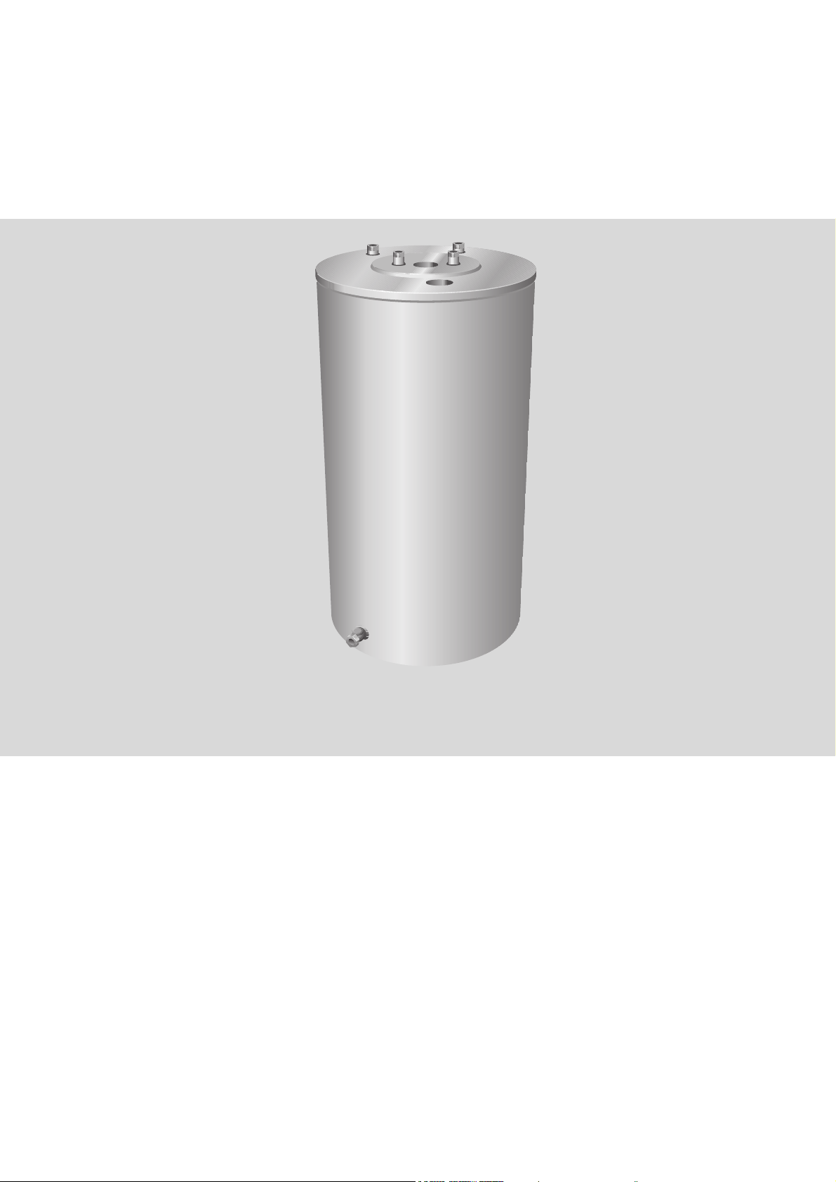
DHW Tank
QWST120 O
6 720 648 100-00.1ITL
6 720 648 071 (2012/03) US
Page 2

Table of Contents
Table of Contents
1 Key to symbols and safety instructions . . . . . . . 3
1.1 Explanation of symbols . . . . . . . . . . . . . . . 3
1.2 Safety instructions . . . . . . . . . . . . . . . . . . 3
2 General points . . . . . . . . . . . . . . . . . . . . . . . . . . 5
2.1 Delivered condition . . . . . . . . . . . . . . . . . . 5
2.2 Tank installation . . . . . . . . . . . . . . . . . . . . 5
3 Moving the tank . . . . . . . . . . . . . . . . . . . . . . . . . 6
4 Dimensions and connections . . . . . . . . . . . . . . . 7
5 Installation . . . . . . . . . . . . . . . . . . . . . . . . . . . . . 8
5.1 Safety limits . . . . . . . . . . . . . . . . . . . . . . . 8
5.2 Connections and fittings . . . . . . . . . . . . . . 8
5.3 Temperature monitoring control options. . 9
5.3.1 Installing the temperature sensor . . . . . . . 9
5.3.2 Installing the Aquastat . . . . . . . . . . . . . . 10
6 Commissioning . . . . . . . . . . . . . . . . . . . . . . . . . 11
7 Maintenance and cleaning . . . . . . . . . . . . . . . . 12
7.1 Checking the magnesium anode . . . . . . . 12
7.2 Cleaning . . . . . . . . . . . . . . . . . . . . . . . . . 13
7.3 Recommissioning after cleaning . . . . . . . 13
8 Spare parts for QWST120 O . . . . . . . . . . . . . . . 14
2
6 720 648 071 (2012/03)
Page 3
1 Key to symbols and safety instructions
Key to symbols and safety instructions
1.1 Explanation of symbols
Warnings
Warnings are indicated in the text by a
warning triangle and a gray background.
In case of danger from electric shock, the
exclamation point on the warning triangle is
replaced with a lightning symbol.
Signal words at the beginning of a warning are used to
indicate the type and seriousness of the ensuing risk if
measures for minimizing damage are not taken.
• NOTICE indicates that minor damage to property may
occur.
• CAUTION indicates possible minor to medium
personal injury.
• WARNING indicates possible severe personal injury.
• DANGER indicates that fatal injury may occur.
Important information
Important information that presents no risk
to people or property is indicated with this
symbol. It is separated by horizontal lines
above and below the text.
Additional symbols
Symbol Function
B Sequence of steps
1.2 Safety instructions
Safety instructions
Failure to observe the safety instructions can result in
serious injury and a risk of fatal injury as well as damage
to property and the environment.
B Read the safety instructions carefully prior to
commissioning the system.
B Ensure that only a trained and certified contractor
carries out installation, commissioning, maintenance
and service.
B Ensure that the system is approved by the local
jurisdiction.
B Clean and perform maintenance at least once a year.
Check that the entire system functions properly at the
same time. Immediately remedy faults.
Danger from failing to consider your own safety in an
emergency such as a fire
B Never put yourself at risk of fatal injury. Your own
safety must always take the highest priority.
Risk of damage from operator error
Operator errors can lead to injuries and/or damage to
property.
B Ensure that only individuals who can operate this
appliance correctly have access to it.
B Installation and commissioning as well as servicing
and maintenance must be carried out only by a
trained and certified contractor.
Æ Cross-reference to other points in this
document or to other documents
• Listing/list entry
– Listing/list entry (2nd level)
Table 1
6 720 648 071 (2012/03)
3
Page 4

Key to symbols and safety instructions
Installation and operation
B Have the appliance installed only by a qualified
contractor.
B Ensure that the hot water tank is completely full prior
to start up.
B To prevent damage from excess pressure, never
disable the safety valves.
B Water may escape from the safety valve when water is
being heated. Ensure that the safety valve is piped to
within 6 inches of the ground in an area where
property damage will not occur.
B Install the unit only in a frost-free room.
B Never store or place combustible material or liquids
near the appliance.
B Maintain safe clearances in accordance with local/
national regulations.
Risk of fatal injury from electric shock
B If an aquastat is used with line voltage, it must be
connected by a licensed electrician. The terminal
wiring diagram must be followed.
B Before carrying out any work, isolate all phases of the
electrical power using the emergency shut-off switch
or by disengaging the heating system circuit breaker.
Secure against unintentional reconnection.
B Do not install this device in rooms with a high
moisture level (e.g. bathrooms, saunas).
Instructing the owner/operator
B Instruct the owner/operator in the functionality and
operation of the appliance.
B Inform the owner/operator that they must never carry
out any modifications or repairs.
B Inform the owner/operator that children
unsupervised by adul ts should never be in the vicinit y
of the heating system.
B Complete the commissioning report in this document
and hand it over to the owner/operator.
B Give the technical documentation to the owner/
operator.
Disposal
B Dispose of packaging in an environmentally
responsible manner.
B Dispose of the appliance correctly at an authorized
disposal site.
Cleaning
B Clean the outside of the appliance with a damp cloth.
Inspection/maintenance
B Recommendation: sign a maintenance and inspection
contract with a qualified heating contractor and have
the appliance serviced annually.
B The owner/operator is responsible for the safety and
environmental compatibility of the system.
B Read and follow the safety instructions in the
"Cleaning and maintenance" chapter.
Original spare parts
Damage caused by spare parts not supplied by the
manufacturer are excluded from our warranty.
B Use only original spare parts and accessories from
the manufacturer.
Frost damage
B When there is a risk of frost, drain the water from the
DHW tank and the heating system's pipework. The
system is protected from frost only if it is completely
dry.
4
6 720 648 071 (2012/03)
Page 5
2 General points
2.1 Delivered condition
The DHW tank QWST120 O Is delivered as a fully
assembled unit.
Additional components supplied with the tank:
1 125 psi P and T valve
3 3/4" brass couplings
1 3/4" brass tee
1 Honeywell L4006 adjustable differential tank
aquastat
1 Aquastat mounting bracket and 4 mounting screws
3 Adjustable tank leg leveling bolts
1 Roll of high quality Teflon tape
2.2 Tank installation
Select a dry, frost free room for installation. The tank
must not be allowed to freeze, or it must be drained or
protected appropriately when not in operation. The floor
must be level and able to carry the weight of the unit.
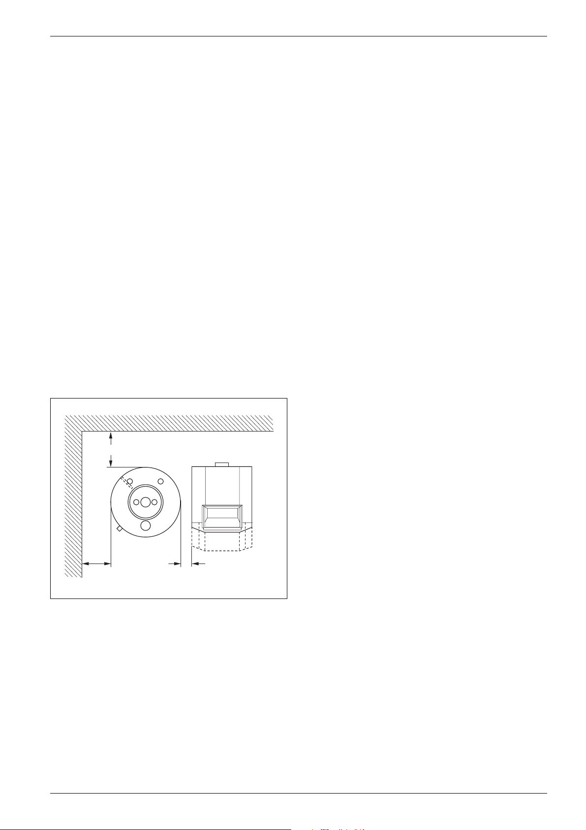
When installing the heating boiler and DHW tank,
observe the minimum clearance requirements for
assembly and service (Æ Fig. 1).
General points
(406 mm)
16"
(406 mm)
16"
min. 4"
Fig. 1 Minimum space requirements for installation
and maintenance
(102 mm)
6 720 648 100-14.1ITL
6 720 648 071 (2012/03)
5
Page 6

Moving the tank
3 Moving the tank
NOTICE: Take care not to damage the tank
when moving it.
B Observe the handling instructions on the
packaging.
B Use suitable means of transportation,
e.g. a hand truck with strap, to handle
this product.
B Move this product upright.
B Prevent impact and shock.
The DHW tank can be moved by means of a hand truck
(accessory, Æ Fig. 2) while still packaged or after
removal of the packaging.
B Position the tank on the hand truck, secure with a
strap if necessary, and transport safely to the
installation location.
B Remove the strap.
B Lay the polystyrene cover [1] on the ground and
carefully lay the DHW tank [2] on its side.
B Remove bottom polystyrene pad and pallet. Install the
adjustable feet M10 x 30 [3].
2 3
3/4 - 1"
(19 - 25 mm)
ca. 0.78"
1
Fig. 3 DHW tank on polystyrene cover pad (illustrative)
6 720 648 100-15.1ITL
6 720 648 100-02.1ITL
Fig. 2 Hand truck (illustrative)
B Remove the plastic wrapping.
B Remove the polystyrene cover pad and 4 wooden
boards.
1 Polystyrene cover pad
2 DHW Tank
3 Adjustable feet
B Place the DHW tank upright.
B Dispose of the DHW tank packaging in an
environmentally responsible manner.
6
6 720 648 071 (2012/03)
Page 7

4 Dimensions and connections
Dimensions and connections
37"
37"
(940 mm)
EL
3/4" - 1"
3/4" - 1"
(19 - 25 mm)
Fig. 4 Dimensions and connections
1 Magnesium anode
AB Hot water outlet
EK Cold water inlet
VS Tank coil supply
RS Tank coil return
MB Hot water temperature sensor or Aquastat
EL Drain
MB
1
EKRSVS
MB
AB
EL
20"
20"
(508 mm)
6 720 648 100-13.1ITL
Type VS RS EK/AB Sacrificial
anode
120 NPT ¾ " NPT ¾ " NPT ¾ " G 1" 158 (72)
Table 2 Dimensions and connections
Weight (empty)
Lbs (kg)
6 720 648 071 (2012/03)
7
Page 8

Installation
5 Installation
B Level the DHW tank by adjusting the feet (Æ Fig. 5).
6 720 648 100-05.1ITL
Fig. 5 Adjusting the feet (illustrative)
5.1 Safety limits
WARNING: Risk of damage to property and
personal injury if temperature / pressure
limits exceeded.
B For safety reasons, never exceed the
following limits.
5.2 Connections and fittings
It is the installer's responsibility to follow national and
local code when installing this tank (Æ Fig. 6).
B Connect all piping to the DHW tank by means of
threaded fittings. For easy service and maintenance,
each connection should be equipped with a shutoff
valve. Install a drain valve [2] in the hot water pipe
upstream and downstream of the shut-off valve [3].
Attach a tag with the following statement to the safety
valve [4]: "Do not close drain line. During heating,
water may be released for safety reasons."
2
3
4
11 10 9 8 6
1
5
6 7 6
Maximum Temperature:
• Heating water (boiler) 230 °F (110 °C)
• Domestic water (DHW tank) 203 °F (95 °C)
Operating pressure:
• Heating water (boiler) 87 psi
1
• Domestic water (DHW tank) 145 psi (10 bar)
12
6 720 648 100-06.1ITL
Fig. 6 Installation (illustrative)
1 Storage tank
2 Purge valve
3 Shut-off valve with drain
4 Pressure and temperature safety valve
5 Flow check valve
6 Shut-off valve
7 DHW recirculation pump (optional)
8 Pressure reducer (if required)
9 Purge valve
10 Backflow preventer
11 Pressure gauge connection
12 Drain
AB Hot water outlet
EK Cold water inlet
EZ Recirculation inlet
EL Drain
1. From the heating system, individual safety equipment
required (safety valve, expansion vessel).
8
6 720 648 071 (2012/03)
Page 9

Installation
WARNING: Precautions must be taken prior
to manually operating the relief valve to
avoid contact with hot water being released
and to prevent water damage.
WARNING: If a relief valve discharges
periodically, this may be due to thermal
expansion in a closed water supply system.
Contact the installer to correct this
situation. Do not plug the relief valve.
B A listed pressure and temperature relief valve (PTRV)
must be installed at the time of installation. No valve
is to be placed between the PTRV and the heater. No
reducing coupling or other restriction may be
installed in the discharge line. The discharge line must
be a minimum of 6" (153 mm) above a drain and
installed such that it allows complete drainage of
both the PTRV and the line. The discharge line must
be placed where it will not cause any water damage.
The location of the PTRV must be readily accessible
for servicing or replacement, and be mounted as close
to the water heater as possible.
B Manually activate the TPRV annually to ensure proper
operation. If the TPRV does not activate it must be
replaced.
B Make sure that the installed pipework and
connections are free of stress.
B Check all connections for leaks! Do not kink or twist
hoses.
Safety valve
Only use approved and listed pressure and temperature
relief valves of the proper size for the output of the tank.
5.3 Temperature monitoring control
options
Install a temperature sensor or an Aquastat on the DHW
tank to measure and monitor the hot water temperature.
5.3.1 Installing the temperature sensor
B Feed the temperature sensor [2] with the spring [1]
into the sensor well [3].
Ensure that the sensor surface has contact
with the sensor well surface over its full
length, and that it cannot accidentally be
pulled out.
3
2
1
6 720 648 100-07.1ITL
Fig. 7 Installing the temperature sensor
1 Spring clip
2 Temperature sensor
3 Sensor well
Minimum
connection
diameter
3/4" 32 (120 liters) 255
Table 3 Safety valve
6 720 648 071 (2012/03)
Nominal capacity
of the water
chamber (gal)
Max. heating
capacity
[kBtu/hr]
9
Page 10

Installation
5.3.2 Installing the Aquastat
DANGER: Risk of fatal injury from electric
shock.
B Disconnect all electrical power before
working on the system.
B Remove cover from the Aquastat.
B If necessary, remove any unnecessary attachments.
Attach bracket [3] to Aquastat [2] by means of 2 selftapping screws [1].
2
3
1
B Feed the temperature probe [4] with the spring [5]
into the sensor well [3]. Ensure that the probe makes
contact with the well wall over its entire length.
B Attach Aquastat [2] to the DHW tank by means of
2 self-tapping screws [1].
2
3
1
4
5
6 720 648 100-09.1ITL
6 720 648 100-08.1ITL
Fig. 8 Attaching the Aquastat to the bracket
1 Self-tapping screws C-ST 4.2x13 mm
2 Aquastat
3 Bracket
Fig. 9 Installing the Aquastat
1 Self-tapping screws C-ST 4.2x13 mm
2 Aquastat
3 Sensor well
4 Temperature sensor
5 Spring
Connect the electrical power and set the
temperature as shown in the manual
supplied with the Aquastat.
B Replace the cover of the Aquastat.
10
6 720 648 071 (2012/03)
Page 11

6 Commissioning
NOTICE: Risk of property damage in the
event of improper operation!
Commissioning with a partially filled tank
can destroy the appliance.
B Check that the DHW tank is completely
filled and that fresh water can enter the
tank.
Prior to commissioning, check for the following and
ensure that systems are connected and operating
properly:
• Absence of leaks in the heating system
• Absence of leaks in the pipework
• Verify all electrical connections
• Consult the operating instructions supplied with the
control unit or boiler (standard delivery - control unit
or boiler) for operating information.
• The system should be commissioned by the installer
in the presence of the owner/operator.
Commissioning
6 720 648 071 (2012/03)
11
Page 12

Maintenance and cleaning
7 Maintenance and cleaning
DANGER: Risk of fatal injury from electric
shock.
B Only trained and certified electricians are
permitted to carry out electrical work.
B Isolate the DHW tank electrically by using
the emergency shut-off switch or by
disengaging the heating system circuit
breaker.
B Secure the DHW tank against
unintentional reconnection.
B Please observe all installation
instructions.
WARNING: Risk of equipment damage from
improper maintenance!
Lack of maintenance or improper
maintenance can result in damage or
destruction of the DHW tank and voiding the
warranty.
B Arrange for regular, thorough, and
professional maintenance of the DHW
tank.
B Protect electrical components and
control units from water and moisture.
7.1 Checking the magnesium anode
The anode rod must be inspected annually
and replaced if compromised. Failure to
operate the tank without a properly
maintained anode rod may void the
warranty.
DANGER: Risk of fatal injury from electric
shock.
B Before working on the system,
disconnect the electrical power.
B Close the cold water inlet (EK); open the tank's drain.
To allow air into the system, open a fixture at a higher
elevation than the drain valve.
B Remove the plastic plugs [1] from the magnesium
anode [2] and inspection port.
B Unscrew the magnesium anode [2].
1
1
2
Use only original spare parts from the
manufacturer or parts approved by the
manufacturer.
Damage caused by spare parts not supplied
by the manufacturer is excluded from our
warranty.
• If not agreed to otherwise in writing, the DHW tank
may be filled only with potable water.
• It is recommended that a qualified installer inspect
and clean the DHW tank at regular intervals of not
more than 2 years.
• In the event of poor water quality (hard to very hard
water) in combination with high temperatures,
inspection and cleaning should be carried out at
shorter intervals.
3
6 720 648 100-10.1ITL
Fig. 10 Installing / removing the magnesium anode
1 Plug (24 mm socket)
2 Magnesium anode (27 mm wrench required)
3 Inspection port (plug, 24 mm socket)
Never bring the magnesium anode surface in
contact with oil or grease. Ensure
cleanliness.
B Check the diameter of the magnesium anode.
B If the diameter is reduced to about 1/2" (13 mm), the
anode rod must be replaced.
12
6 720 648 071 (2012/03)
Page 13

Maintenance and cleaning
7.2 Cleaning
B Unscrew the plug [1] from the inspection port.
1
6 720 648 100-11.1ITL
Fig. 11 Unscrewing the plug
1 Plug (24 mm socket)
2 Inspection port
NOTICE: Risk of physical damage to the
DHW tank if limescale is broken up with
sharp implements.
B Never break up limescale deposits with
hard or sharp implements as this may
damage the surface coating on the inside
of the tank.
7.3 Recommissioning after cleaning
B Seal the magnesium anode [2] back into place.
B Seal the plug [3] back into the inspection port.
1
1
2
2
3
6 720 648 100-10.1ITL
Fig. 12 Installing / removing the magnesium anode
1 Plastic plugs
2 Magnesium anode (27 mm wrench required)
3 Inspection port (plug, 24 mm socket)
B Start up the system again.
B Check all threaded connections for leaks.
B Install the plastic plugs [1] at the magnesium anode
and inspection port.
B Inspect and clean the interior of the tank.
B To clean the coil run the boiler to heat the coil, then
spray down with cold water.
B Drain all debris from the tank.
6 720 648 071 (2012/03)
13
Page 14

Spare parts for QWST120 O
8 Spare parts for QWST120 O
50
5
80
50
10
80
100
70
20
40
90
110
60
30
6 720 648 100-12.1ITL
Fig. 13 Spare parts for QWST120 O
Item no. Article description Product No. Number
5 DHW tank QWST120 O, complete 8 718 543 265 1
10 Magnesium anode D26 × 505 mm, G1" 87 185 713 470 1
20 Plug 63 004 276 1
30 Bracket for Aquastat 63 032 088 1
40 Casing lid, white 77 470 110 240 1
50 Self-tapping screw DIN 7981-C-ST6.3 × 19 - A3T 73 986 10
60 Spring clip 87 182 240 810 1
70 Fill & drain valve 87 185 433 400 1
80 Plastic plug, white 87 185 433 390 2
90 Hex-head bolt ISO 4017- M10 × 30 - 8.8 - A3K 7 747 022 050 1
100 Immersion pipe, 1-1/4" (31 mm) long 7 747 020 191 1
110 Immersion pipe, 32" (813 mm) long 7 747 020 190 1
Table 4 Spare parts available for the QWST120 O from Bosch
14
6 720 648 071 (2012/03)
Page 15

Notes
6 720 648 071 (2012/03)
15
Page 16

United States and Canada
Bosch Thermotechnology Corp.
50 Wentworth Avenue
Londonderry, NH 03053
U.S.A.
Tel. 03-552-1100
Fax 603-584-1681
www.bosch-climate.us
Bosch Thermotechnology Corp. reserves the right
to make changes without notice due to continuing
engineering and technological advances.
 Loading...