


Bosch PR109B, PR110B Reference Manual
PR109B and PR110B
LAN Reader Module
Security Systems
EN
Installer Reference Guide
Security System
PR109B-PR110B
i
Note
Installer Reference Guide
LAN Readers
PR109B - Black and PR110B - White
The PR109B and PR110B LAN readers feature our proprietary 40 bit
transmission format and can be used to provide alarm and or access control functionality when used on selected Solution security
control panels.
Reader Compatibility
Panels Supported Version Keypads Supported
Solution 16i 2.19 Up to 8
Solution 16X 2.00 Up to 8
Solution 144 GRAPHIC 2.00 Up to 16
Solution GRAPHIC 2.00 Up to 16
Table 1: LAN Reader Compatibility
The PR109B and PR110B readers include red, green and blue indicators which are used to show area and or door lock status at all times.
The reader connects to the control panel via the RS485 encrypted
LAN and occupies a standard keypad position in the panel configuration.
Various options can be configured via the Devices - Keypad & Readers menu in panel programming. User access events are stored in
the panel log and can also be reported if required.
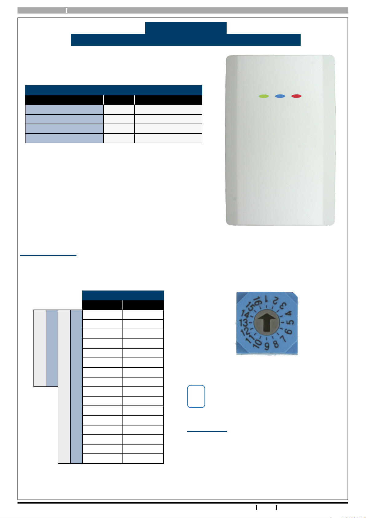
Reader Addressing
Each reader fitted to the system must be assigned a unique address on the LAN.
The PR109B and PR110B readers include a rotary address switch for quick selection. The following table shows the
address setting for each reader as well as the number of keypad, reader devices each panel can support.
Reader Address Setting
Address No Keypad No
1 1
2 2
3 3
4 4
5 5
6 6
Solution 16i Panel
Solution 16X Panel
Solution 144 Panel
Solution GRAPHIC Panel
Table 2: Address Table
7 7
8 8
9 9
10 10
11 11
12 12
13 13
14 14
15 15
16 16
Only 1 reader can be assigned to each address. All
readers are supplied from the factory set to address
1. You must power cycle the panel or perform a
LAN scan whenever you change the reader address.
Box Contents
The PR109B and PR110B contains the following parts.
Reader Base Unit
Reader Cover
Mounting Template
Instruction Sheet
2 x (M3 x 6mm) Hex Screw
1 x 2mm Hex Key
Figure 1: PR110B Reader
Figure 2: Address Switch
2
Bosch Security Systems 09/11 PR109B-PR110BIRG FTR1.1
PR109B-PR110B Installer Reference Guide
i
Note
i
Note
Installation
The reader should be installed onto a solid surface using
suitable mounting fixtures. Wiring should only be
performed while the control panel is powered off.
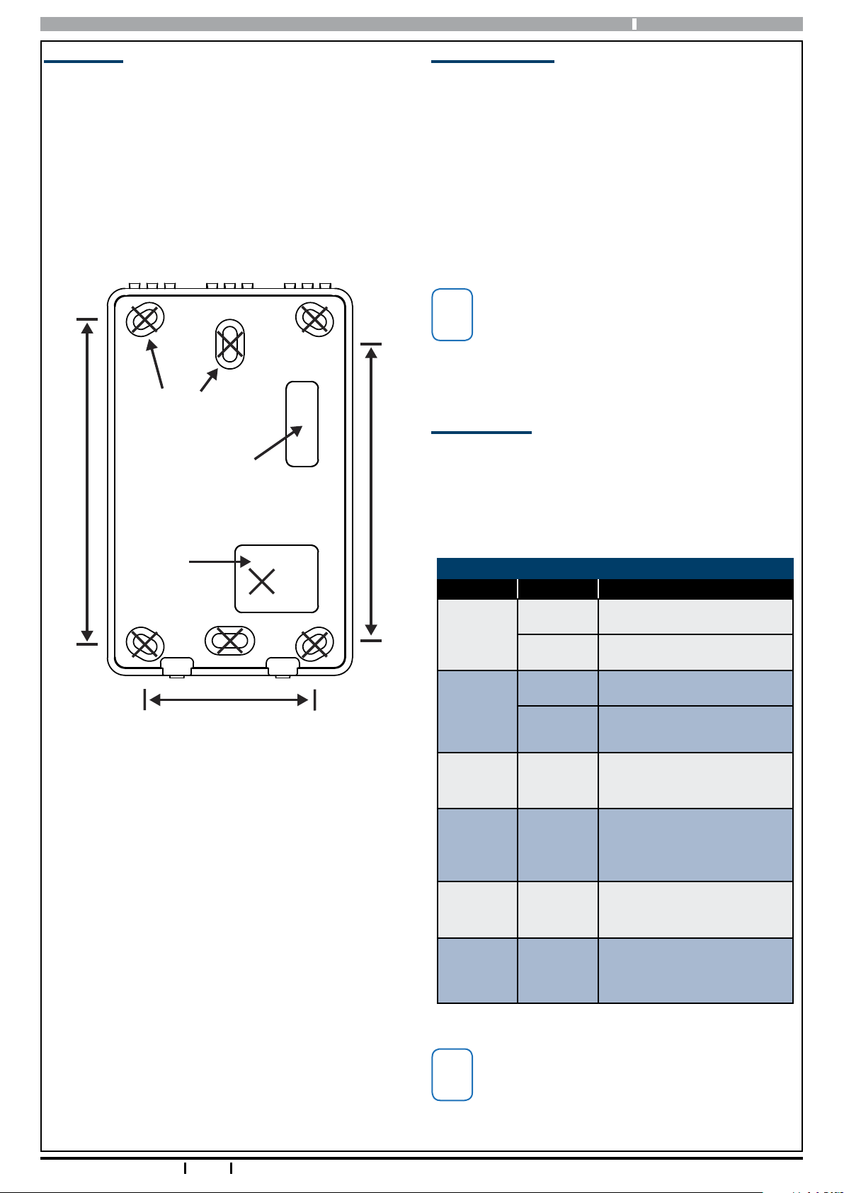
Step 1) Using the 1:1 mounting template supplied, mark
out the location of the 2 mounting holes and
the cable exit hole before drilling out all points
as necessary.
PR109B & PR110B Mounting Template
Scale 1:1
6 x 4.0mm
(1/8”) holes
Tamper Switch
Do Not Create A Hole
92.0mm
In This Location
84.0mm
Reader Operation
LAN Readers can be configured to provide system area
control, door access control or both depending on the
installation requirements.
As there is no LCD display on the readers, feedback is
provided via the red, green and blue indicators and the
reader sounder.
The readers also include an egress input and lock output
which can be used to control door access if required.
Using the on board lock output is not recommend-
ed when the reader is being used on an external
wall of the building. In this case it is recommended
that you run the lock control wires directly to an
output located on the main panel or output expander module located inside the building.
LED Indicators
The Red and Green indicators on the reader show area
status while the Blue indicator shows door status. The
addition of the Blue indicator allows the system to
display both area and door status at the same time if
required.
Connection Cable
Entry Point
48.0mm
Rev 1PR109B & PR110B Mounting Template.ai
Figure 3: Mounting Template (Not to Scale)
Step 2) If the reader is to occupy an address on the
LAN other than address 1, you will need set the
required address before mounting. Note each
reader on the system must have a unique
address. See Table 2: for more information.
Step 3) Once the address has been set, terminate the
required wires referring to the Connection Diagram on page 6. Unused wires should be insulated to prevent short circuits.
LED Operation For Area Control
Led Condition Meaning
On Area All On
Red
Flashing Area Alarm
On Area is OFF
Green
Red &
Green
Red &
Green
Red &
Green
Red &
Green
Flashing
Both On
Red On
and Green
Flashing
Alternate
Flashing
Both Off
Area not ready to turn on zone(s) unsealed
Area armed in Part mode
and all zones sealed.
Area armed in Part mode
with zones unsealed.
Keypad initialising during
power up or LAN scan.
Home Area and Access
Group not programmed or
keypad not powered.
Step 4) If using the on board lock output to open the
door, you must make sure to use a relay and
protection diode as shown.
Step 5) Once the wiring is complete, mount the reader
to the wall and fit the cover plate using the M3 x
6mm hex screws.
Bosch Security Systems 09/11 PR109B-PR110BIRG FTR1.1
Table 3: Reader LED’s - Area Control
The LED indicators will only display the status of
the programmed home area. You cannot move
between areas from this reader. If you require multiple area status visibility you should use a display
keypad like the CP700B.
3
 Loading...