

Bosch PL2632 Operating/safety Instructions Manual
IMPORTANT: IMPORTANT : IMPORTANTE:
Read Before Using Lire avant usage Leer antes de usar
For English Version Version française Versión en español
See page 2 Voir page 17 Ver la página 32
Operating/Safety Instructions
Consignes de fonctionnement/sécurité
Instrucciones de funcionamiento y seguridad
1-877-BOSCH99 (1-877-267-2499) www.boschtools.com
Call Toll Free for
Consumer Information
& Service Locations
Pour obtenir des informations
et les adresses de nos centres
de service après-vente,
appelez ce numéro gratuit
Llame gratis para
obtener información
para el consumidor y
ubicaciones de servicio
PL2632
2610035786 PL2632 01-15.qxp_PL2632 1/14/15 9:33 AM Page 1

-2-
Work area safety
Keep work area clean and well lit. Cluttered
or dark areas invite accidents.
Do not operate power tools in explosive
atmospheres, such as in the presence of
flammable liquids, gases or dust. Power
tools create sparks which may ignite the dust
or fumes.
Keep children and bystanders away while
operating a power tool. Distractions can
cause you to lose control.
Electrical safety
Power tool plugs must match the outlet.
Never modify the plug in any way. Do not
use any adapt e r plugs with earth e d
(grounded) power tools. Unmodified plugs
and matching outlets will reduce risk of
electric shock.
Avoid body contact with earthed or grounded
surfaces such as pipes, radiators, ranges
and refrigerators. There is an increased risk
of electric shock if your body is earthed or
grounded.
Do not expose power tools to rain or wet
conditions. Water entering a power tool will
increase the risk of electric shock.
Do not abuse the cord. Never use the cord
for carrying, pulling or unplugging the power
tool. Keep cord away from heat, oil, sharp
edges or moving parts. Damaged or entangled
cords increase the risk of electric shock.
When operating a power tool outdoors,
use an extension cord suitable for outdoor
use. Use of a cord suitable for outdoor use
reduces the risk of electric shock.
If operating a power tool in a damp location
is unavoidable, use a Ground Fault Circuit
Interrupter (GFCI) protected supply. Use of
an GFCI reduces the risk of electric shock.
Personal safety
Stay alert, watch what you are doing and
us e co mmon sense w hen oper ating a
power tool. Do not use a power tool while
you are tired or under the influence of drugs,
alcohol or medication. A moment of inattention
while operating power tools may result in
serious personal injury.
Use personal protective equipment. Always
wear eye protection. Protective equipment
such as dust mask, non-skid safety shoes, hard
hat, or hearing protection used for appropriate
conditions will reduce personal injuries.
Prevent unintentional starting. Ensure the
sw itch is in the off-position before
connecting to power source and / or battery
pa ck, picking up or car rying the tool.
Carrying power tools with your finger on the
switch or energizing power tools that have the
switch on invites accidents.
Remove any adjusting key or wrench before
turning the power tool on. A wrench or a
key left attached to a rotating part of the
power tool may result in personal injury.
Do not overreach. Keep proper footing and
balance at all times. This enables better
control of the power tool in unexpected
situations.
Dress properly. Do not wear loose clothing
or jewelry. Keep your hair, clothing and
gloves away from moving parts. Loose
clothes, jewelry or long hair can be caught in
moving parts.
If devices are provided for the connection
of dust extraction and collection facilities,
ensure these are connected and properly
used. Use of dust collection can reduce dust-
related hazards.
Power tool use and care
Do not for ce the powe r tool. Use the
correct power tool for your application. The
correct power tool will do the job better and
safer at the rate for which it was designed.
Do not use the power tool if the switch does
not turn it on and off. Any power tool that
cannot be controlled with the switch is
dangerous and must be repaired.
Read all safety warnings and all instructions. Failure to follow the warnings
and instructions may result in electric shock, fire and/or serious injury.
SAVE ALL WARNINGS AND INSTRUCTIONS FOR FUTURE REFERENCE
The term “power tool” in the warnings refers to your mains-operated (corded) power tool or
battery-operated (cordless) power tool.
!
WARNING
General Power Tool Safety Warnings
2610035786 PL2632 01-15.qxp_PL2632 1/14/15 9:33 AM Page 2

-3-
Disconnect the plug from the power source
a
nd/or the battery pack from the power tool
before making any adjustments, changing
accessories, or storing power tools. Such
preventive safety measures reduce the risk of
starting the power tool accidentally.
Store idle power tools out of the reach of
children and do not allow persons unfamiliar
with the power tool or these instructions to
operate the power tool. Power tools are
dangerous in the hands of untrained users.
Maintain power tools. Check for misalignment
or binding of moving parts, breakage of
parts and any other condition that may
affect the power tool’s operation. If damaged,
have the power tool repaired before use.
Many accidents are caused by poorly
maintained power tools.
Keep cutting tools sharp and clean. Properly
m
aintained cutting tools with sharp cutting
edges are less likely to bind and are easier to
control.
Use the power tool, accessories and tool
bits etc. in accordance with these instructions,
taking into account the working conditions
and the work to be performed. Use of the
power tool for operations different from those
intended could result in a hazardous situation.
Service
Have your power tool serviced by a qualified
rep a i r per s o n usi n g only identi c al
replacement parts. This will ensure that the
safety of the power tool is maintained.
Safety Rules for Planers
Wait for the cutter to stop before setting the
tool down. An exposed rotating cutter may
engage the surface leading to possible loss of
control and serious injury.
Hold the power tool by insulated gripping
surfaces only, because the cutter may
contact its own cord. Cutting a "live" wire
may make exposed metal parts of the tool
"live" and could give the operator an electric
shock.
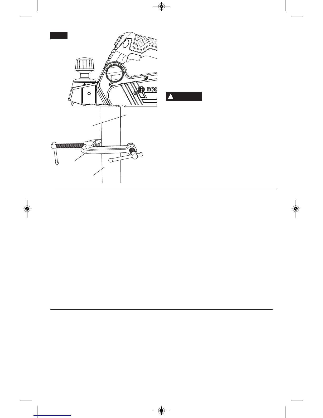
Use clamps or another practical way to
secure and support the workpiece to a
stable platform. Holding the work by hand or
against the body leaves it unstable and may
lead to loss of control.
Always start the planer before blade is in
contact with the workpiece and allow the
blade to come to full speed. Tool can
vibrate or chatter if blade speed is too slow at
beginning of cut and possibly kickback.
Check the workpiece for nails, if there are
nai ls, eit her rem ove or set the m well
below intended finished surface. If the
planer blades strike objects like nails it may
cause the tool to kickback and serious
personal injury may result.
Unplug t h e planer b efore c h a n g i n g
accessories. Before plugging the tool in,
chec k that the t r igger lock is "OFF".
Accidental start-ups may occur if planer is
plugged in while changing an accessory.
After changing blades, rotate the blade
drum to make sure blades are not hitting
any part of the blade head housing and
the blade locking scr e w s a r e t i g h t.
Spinning blades could strike tool housing and
damage tool as well as possible injury.
Al ways hold the tool firmly w ith both
hands for maximum control.
Never pull the plane backward over the
workpiece. Loss of control may occur.
Do not put fingers or any objects into the
shavings exhaust port or clean out
shavings while tool is running. Contact
with blade drum will cause injury.
Rem ove plu g from power s ource i f it
becomes necessary to remove chips. The
blades are hidden from view and you may be
cut if blade is contacted.
Never use dull or damaged blades. Sharp
blades m u st b e handled with c a r e .
Damaged blades can snap during use. Dull
blades require more force to push the tool,
possibly causing the blade to break.
2610035786 PL2632 01-15.qxp_PL2632 1/14/15 9:33 AM Page 3

-4-
Additional Safety Warnings
GFCI and personal protection devices like
electrician’s rubber gloves and footwear will
further enhance your personal safety.
Do not use AC only rated tools with a DC
power supply. While the tool may appear to
work, the electrical components of the AC
rated tool are likely to fail and create a hazard
to the operator.
Keep handles dry, clean and free from oil
and grease. Slippery hands cannot safely
control the power tool.
Develop a periodic maintenance schedule
for your tool. When cleaning a tool be
careful not to disassemble any portion of
th e tool since internal wire s may be
misplaced or pinched or safety guard return
sp ring s may be impro perl y mounted.
Certain cleaning agents such as gasoline,
carbon tetrachloride, ammonia, etc. may
damage plastic parts.
Risk of injury to user. The power cord must only
be serviced by a Bosch Factory Service Center
or Autho rized Bosch Service Station.
Some dust created by power
sanding, sawing, grinding,
drilling, and other construction activities
contains chemicals known to cause cancer,
birth defects or other reproductive harm.
Some examples of these chemicals are:
• Lead from lead-based paints,
• Crystalline silica from bricks and cement and
other masonry products, and
• Arsenic and chromium from chemically-
treated lumber.
Your risk from these exposures varies,
depending on how often you do this type of
work. To reduce your exposure to these
chemicals: work in a well ventilated area, and
work with approved safety equipment, such as
those dust masks that are specially designed
to filter out microscopic particles.
!
WARNING
2610035786 PL2632 01-15.qxp_PL2632 1/14/15 9:33 AM Page 4

-5-
IMPORTANT: Some of the following symbols may be used on your tool. Please study them
and learn their meaning. Proper interpretation of these symbols will allow you to operate the
tool better and safer.
Symbol Name Designation/Explanation
V Volts Voltage (potential)
A Amperes Current
Hz Hertz Frequency (cycles per second)
W Watt Power
kg Kilograms Weight
min Minutes Time
s Seconds Time
Diameter Size of drill bits, grinding wheels, etc.
n
0
No load speed Rotational speed, at no load
n Rated speed Maximum attainable speed
.../min Revolutions or reciprocation Revolutions, strokes, surface speed,
per minute orbits etc. per minute
0 Off position Zero speed, zero torque...
1, 2, 3, ... Selector settings Speed, torque or position settings.
I, II, III, Higher number means greater speed
Infinitely variable selector with off Speed is increasing from 0 setting
Arrow Action in the direction of arrow
Alternating current Type or a characteristic of current
Direct current Type or a characteristic of current
Alternating or direct current Type or a characteristic of current
Class II construction Designates Double Insulated
Construction tools.
Earthing terminal Grounding terminal
Warning symbol Alerts user to warning messages
Li-ion RBRC seal Designates Li-ion battery recycling
program
Ni-Cad RBRC seal Designates Ni-Cad battery recycling
program
Read manual symbol Alerts user to read manual
Wear eye protection symbol Alerts user to wear eye protection
Symbols
0
2610035786 PL2632 01-15.qxp_PL2632 1/14/15 9:33 AM Page 5

-6-
This symbol designates that this tool is listed by Underwriters Laboratories.
This symbol designates that this tool is listed by the Canadian Standards
Association.
This symbol designates that this tool is listed by the Canadian Standards
Association, to United States and Canadian Standards.
This symbol designates that this tool complies to NOM Mexican Standards.
This symbol designates that this tool is listed by the Intertek Testing
Services, to United States and Canadian Standards.
Symbols (continued)
IMPORTANT: Some of the following symbols may be used on your tool. Please study them
and learn their meaning. Proper interpretation of these symbols will allow you to operate the
tool better and safer.
This symbol designates that this component is recognized by Underwriters
Laboratories.
This symbol designates that this tool is listed by Underwriters Laboratories,
to United States and Canadian Standards.
2610035786 PL2632 01-15.qxp_PL2632 1/14/15 9:33 AM Page 6
-7-
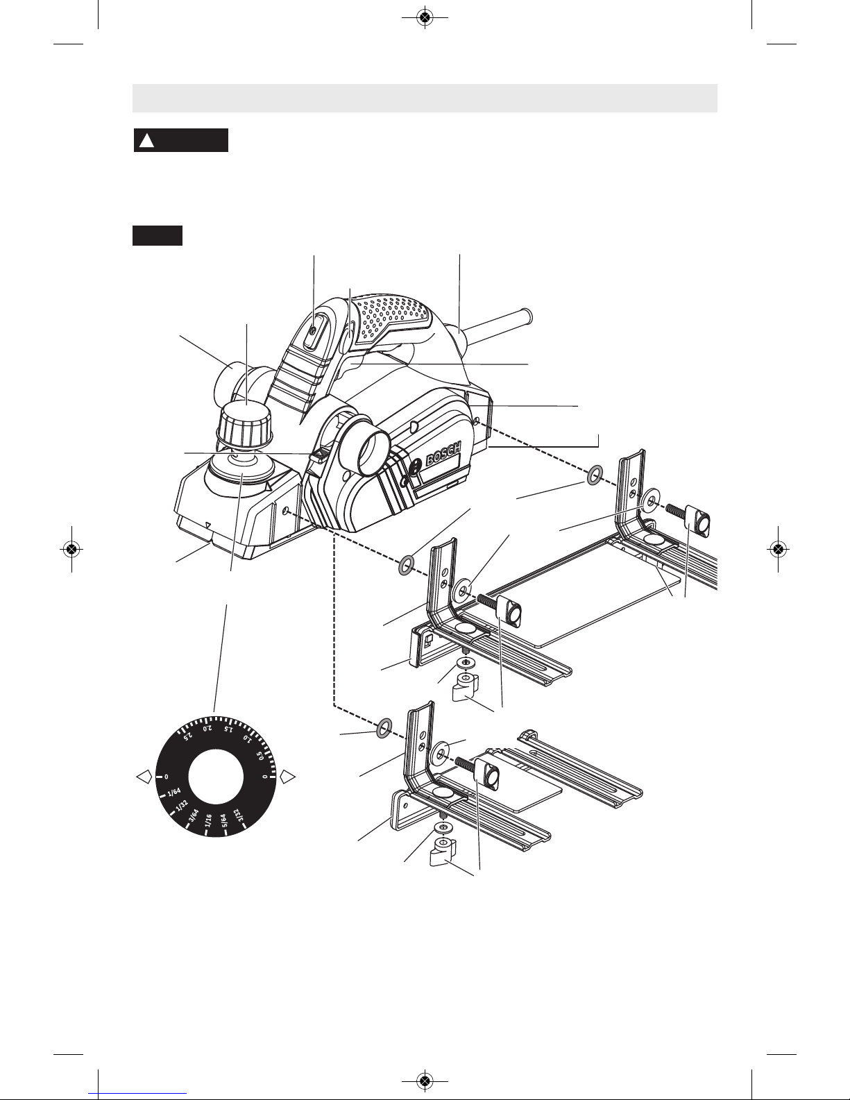
Functional Description and Specifications
Dis connect the p l ug from the p ower s ource b efore making any
assembly, adjustments or changing accessories. Such preventive safety
measures reduce the risk of starting the tool accidentally.
!
WARNING
PL2632 Planer
PORT
SELECTOR
LEVER
Maximum Capacities
Planing depth 0 - 5/32" (0 - 2.6mm)
Rabbeting depth 0 - 5/16" (0 - 9mm)
Planing width 3-1/4" (82mm)
NOTE: For tool specifications refer to
the nameplate on your tool.
GUIDE
BRACKET
DEPTH
ADJUSTMENT
KNOB
SHAVINGS
EXHAUST
PORT
GUIDE
BRACKET
FENCE
CHAMFER
V-GROOVE
WASHER
WASHER
WASHER
WASHER
O-RING
O-RING
FIG. 1
TRIGGER SWITCH
W
R
EN
C
H
S
TO
R
A
G
E A
R
EA
“LOCK-ON”
BUTTON
“LOCK OFF”
BUTTON
BALL-JOINT
CORD SWIVEL
WING KNOBS
WING KNOBS
FENCE
PLANER STAND
DEPTH
SCALE
Dual-Mount
Guide Fence
PA1207
Basic Guide
Fence
WING KNOBS
2610035786 PL2632 01-15.qxp_PL2632 1/14/15 9:33 AM Page 7
Assembly
-8-
GUIDE FENCES
Purposes of Guide Fences
The Bosch planer guide fences all have a
protective shield that covers the unused
section of the blade. Therefore, we
recommend always attaching a planer guide
fence (except in situations when the planing
takes place farther in from the edge of a
workpiece than the width of the planer blade
and would interfere with the work).
All of the Bosch planer guide fences can be
used to control the width of the cut, such as
when creating rabbets (See page 14).
All of the Bosch planer guide fences also
provide added stability when planing materials
that are up to 3-1/4" wide.
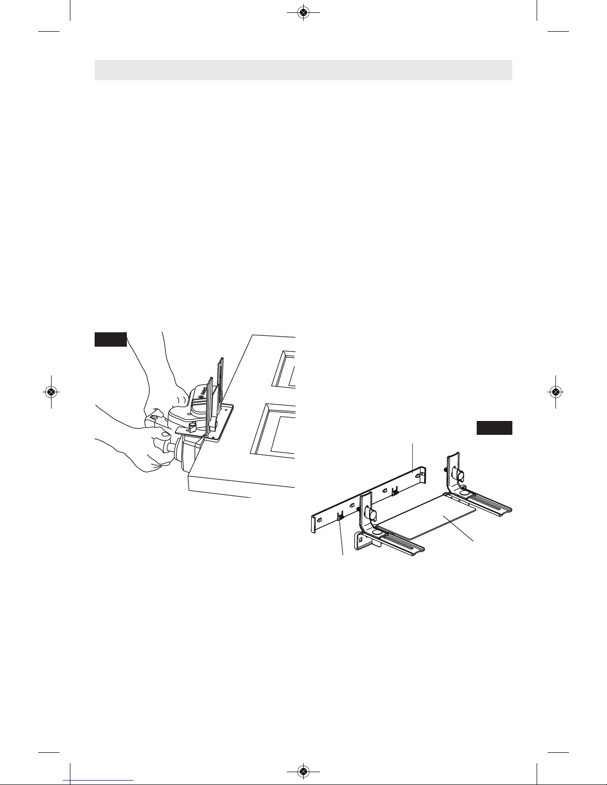
The optional dual-mount guide fence is
especially helpful when planing a vertical edge,
such as when planing an un-mounted door
that is laid flat, such as on saw horses. (Fig. 2)
Positioning of Guide Fences
For right-handed use, the guide fence should
be installed on the left side of the tool. For lefthanded use, the guide fence should be
installed on the right side of the tool, except
when using the planer to create rabbets, which
requires the guide fence to be installed on the
left side of the tool.
Installation of Basic Guide Fence
1. Place a wing screw through the bottom hole
in the long end of the bracket and screw into
the front mount on the appropriate side of
the planer and securely tighten wing knob.
(The O-ring should be on the backside of
the bracket and the flat washer between the
back of the knob and the front side of the
bracket.)
2. Place the bolt through the top of the hole on
the short end of the bracket and then
through the slot in the appropriate arm of the
fence. Place the flat washer on the bottom of
the bolt below the guide fence’s arm and
then install wing knob. If the washer is not
installed, the guide fence is likely to slip.
3. Securely tighten wing knob.
Installation of Dual-Mount Guide Fences
• This is the same as installing the Basic
Guide Fence, except that both brackets are
attached to the planer’s front mount area
and rear mount area (Fig. 1).
Attachment of Plastic Overshoe to Dual-
Mount Guide Fences
• There are two plastic overshoes that can be
used with the dual-mount fence, a straight
overshoe and 3-degree overshoe (sold
separately).
• The 3-degree bevel plastic overshoe is
especially useful when planing the long
edges of typical doors.
• The overshoes clip onto the steel fence.
• To remove either overshoe, gently pull tabs
on overshoe away from the fence and then
move overshoe upward (Fig. 2a).
Setting The Desired Planing Width
1. Loosen the wing knob(s) that hold the fence
onto the brackets guide bracket(s).
2. Slide the fence along the guide bracket(s) to
the desired planing width. (When using the
dual-mount fence, it may be necessary to
raise the planer stand before the desired
width can be reached.)
3. Securely tighten wing knobs.
FIG. 2
PLASTIC
OVERSHOE
DUAL-MOUNT
GUIDE FENCE
TABS (3x)
FIG. 2a
2610035786 PL2632 01-15.qxp_PL2632 1/14/15 9:33 AM Page 8
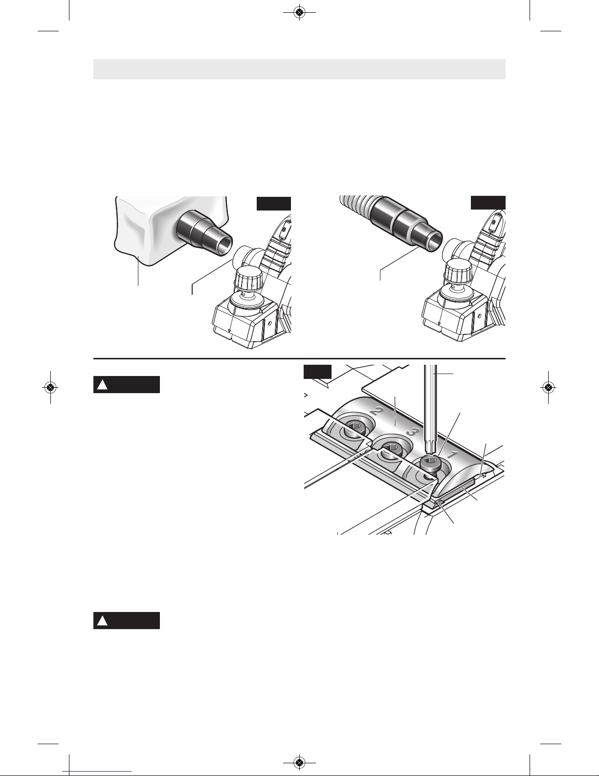
Assembly
FIG. 3a
SHAVINGS
BAG
SHAVINGS
EXHAUST
PORT
SH
A
VI
N
G
S
EXT
R
A
C
T
I
O
N
T
he P
L2632
pl
aner c
om
es
w
i
t
h
t
w
o
s
hav
i
ngs
ex
haus
t
por
t
s
.
M
ov
i
ng
t
he
por
t
s
el
ec
t
or
l
ev
er
t
o
p
o
si
ti
o
n
1
(
to
w
a
r
d
s
fr
o
n
t
o
f
to
o
l
)
d
i
sch
a
r
g
e
s
s
hav
i
ngs
t
o t
he
l
ef
t
,
w
hi
l
e
pos
i
t
i
on 2 (t
ow
ards
re
a
r o
f
t
o
o
l
)
d
i
s
c
h
a
rg
e
s
s
h
a
v
i
n
g
s
t
o
t
h
e
ri
g
h
t
.
(
F
i
g.
1)
.
T
he
pl
aner
s
hav
i
ngs
ex
haus
t
por
t
m
ay
be
us
ed
wi
t
h
an opt
i
onal
shavi
ngs
bag
(
Fi
g.
3a)
or
a
s
hop
v
ac
uum
and
v
ac
uum
c
onnec
t
or
(
F
i
g.
3b)
t
o
k
eep
y
our
w
or
k
env
i
r
onm
ent
c
l
eaner
.
B
o
s
c
h
o
f
f
e
r
s
s
e
v
e
r
a
l
d
if
f
e
r
e
n
t
v
a
c
u
u
m h
o
s
e
s
t
hat
w
i
l
l
c
onnec
t
t
hes
e t
ool
s
t
o Bos
c
h v
ac
uum
c
l
e
a
n
e
r
s
. T
h
e
o
p
ti
o
n
a
l
B
o
s
c
h
V
A
C
0
0
2
o
r
V
A
C
0
2
4
a
d
a
p
te
r
s
w
i
l
l
co
n
n
e
ct
th
e
p
l
a
n
e
r
to
1
-
1
/4
”
a
n
d
1
-
1
/2
”
va
cu
u
m
h
o
se
s,
a
n
d
th
e
opt
i
onal
VAC
020
w
i
l
l
c
onnec
t
t
he
pl
aner
t
o
2
-
1/
2"
hoses.
FIG. 3b
VACUUM
HOSE ADAPTER
(OPTIONAL)
PLANER BLADES
The planer blades are sharp
and frag ile a nd m ust b e
handled carefully to avoid injury to the user
or damage to the blades.
• There are three types of blades that can be
used with the Bosch PL2632 planer; standard
mini tungsten carbide blades, Bosch
Woodrazor micrograin mini tungsten carbide
blades (standard equipment with the Bosch
PL2632 planer), and large HSS blades.
• While the Bosch PL2632 mini tungsten
carbide blades are sharper and more durable
than standard mini tungsten carbide blades,
the assembly and adjustment of both of
Woodrazor and standard tungsten carbide
blades are the same. Henceforth, all
references in this manual to “mini TC blades”
refer to both Woodrazor blades and standard
mini tungsten carbide blades.
• To use large HSS blades with the PL2632 it
is necessary to purchase optional accessories.
Wear prote ctive g loves
when chang ing plan er
blades. Edges are sharp and may cause
injury.
REMOVING MINI TUNGSTEN CARBIDE
BLADES
Mini TC planer blades have two cutting edges,
and may be reversed when one of the cutting
edges becomes dull or chipped. (Fig. 6) Before
any work on the machine itself, pull the power
plug.
Always change both blades at the same time.
Otherwise, imbalance can cause vibration and
reduce the useful service life of the tool. Use
only blades designated for use with this model,
because other blades can cause vibration,
decrease performance and may not clamp
securely in blade holder. Do not attempt to
sharpen or use re-sharpened any TC blades.
To remove the blades:
1. Rotate the blade drum until the clamping jaw
is parallel to the planer shoe.
!
WARNING
!
WARNING
FIG. 4
CLAMPING
SCREW
FRONT
SHOE
BLADE
HOLDER
RIDGE
CLAMPING
JAW
BLADE
DRUM
BLADE
WRENCH
-9-
2610035786 PL2632 01-15.qxp_PL2632 1/14/15 9:33 AM Page 9

-10-
2. Loosen the three clamp screws by about
one revolution each. (It is not necessary to
remove the clamping jaw.) (Fig. 4)
3. Slightly rotate the blade drum and use a
piece of wood to push the blade sideways and
out from under the clamping jaw. Make sure to
keep your fingers away from the sharp edges
of the blade. If the blade is gummed and
difficult to remove, you may clean the blade
and clamp with mineral spirits, lacquer thinner
or alcohol. (Fig. 5)
4. Rotate the blade drum 180° and repeat the
procedure to remove the second blade. Before
inserting a new or sharpened blade, clean all
surfaces (blades, retainer and drum) with
mineral spirits; lacquer thinner or alcohol, as
this will ensure an accurate blade setting and
proper tool performance.
INSTALLING AND ADJUSTING MINI
CARBIDE BLADES
If the blades and/or holder are gummed and
difficult to remove, remove the clamping jaws
and screws and clean all surfaces with mineral
spirits; lacquer thinner or alcohol, as this will
ensure an accurate blade setting and proper
tool performance. (See REMOVAL OF MINI
TC BLADE HOLDERS AND RETAINERS)
To install, carefully slide the blades onto ridges
on the blade holders.
To ensure proper operation and an even cut,
the blades must be positioned so that they are:
• Centered relative to the front and rear shoes.
• Aligned with each other.
• Positioned so that they will not touch against
any part of the planer when rotated.
• Evenly pressed back toward the holder to
ensure that they are level.
INSTALLATION PROCEDURE
1. Align the groove on top of the blade with the
ridge of the blade holder and carefully slide the
blade onto the blade holder, as shown in
Figure 6.
2. Using a block of wood push the TC blade
back towards the blade holder so that the inner
side of the blade is pressed against the sloping
part of the blade holder. (This will ensure that
the blades are level.)
3. Then tighten the Torx clamping screws
using the correct tightening sequence (1,2,3),
as shown in Figure 4, and your planer is ready
for use.
Blade Retainer Screws - Under normal
circumstances, the position of the retainer on
the mini TC blade holders does not require
readjustment. If fact, the screws that attach the
retainer to the blade holder are factory sealed
with a yellow fastening compound that should
not be disturbed. However, if you believe that
adjustments must be made, proper adjustment
is critical, and it is best performed by a Bosch
Factory Service or Bosch Authorized Service
Center.
CONVERSION TO HIGH-SPEED STEEL
BLADES
The PL2632 Planer can be converted to
accept large HSS blades. The conversion
requires the optional PA1204 HSS Blades with
Retainers (pair). (Fig. 7) Additional pairs of
HSS blade, the PA1205 large HSS blades, can
also be purchased separately.
FIG. 7
HSS
BLADE
BLADE
RETAINER
F
I
G.
6
BLADE
HOLDER
FIG. 5
2610035786 PL2632 01-15.qxp_PL2632 1/14/15 9:33 AM Page 10
REMOVAL OF MINI TC BLADE HOLDERS
AND RETAINERS
1. Rotate the blade drum until the clamping jaw
is parallel to the planer shoe.
2. Loosen the three clamp screws completely
and remove the screws and clamping jaw.
3. Slightly rotate the blade drum and use a
piece of wood to push the blade, holder and
retainer off of the blade drum. Make sure to
keep your fingers away from the sharp edges
of the blade. If the blade is gummed and
difficult to remove, you may clean the blade
and clamp with mineral spirits, lacquer thinner
or alcohol.
4. Rotate the blade drum 180° and repeat the
procedure to remove the second blade.
INSTALLING AND ADJUSTING HSS
BLADES AND RETAINERS
Before inserting a new or sharpened blade,
clean all surfaces (blades, retainer and drum)
with mineral spirits; lacquer thinner or alcohol,
as this will ensure an accurate blade setting
and proper tool performance.
New or re-sharpened plane blades must be
properly leveled before installation using the
optional PA1206 HSS Blade Leveling Fixture.
(The PA1204 HSS Blades with Retainers are
leveled at the factory.)
To ensure proper operation and an even cut,
the blades must be positioned so that they are:
• Centered relative to the front and rear shoes.
• Aligned with each other.
• Positioned so that they will not touch against
any part of the planer when rotated.
Procedure:
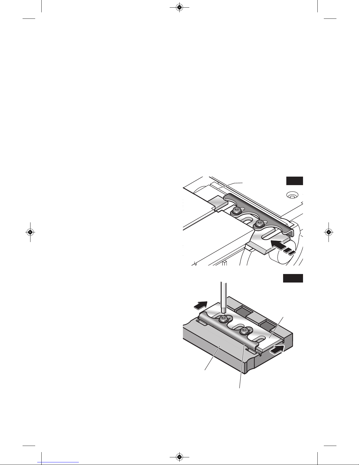
1. To install the blades, carefully slide the
blade/retainer assembly sideways to over one
of the two clamping areas on the blade drum.
The retainer must engage in the groove. (Fig.
8)
2. Place a properly-oriented clamping jaw over
the blade. (Fig. 4)
3. Tighten the three clamp screws with the
Torx key using the correct tightening sequence
(1,2,3). (Fig. 4)
4. Rotate the blade drum 180° and repeat the
procedure for the second blade clamp.
REMOVING LARGE HSS BLADES
To remove the blades:
1. Rotate the blade drum until the clamping jaw
is parallel to the planer shoe.
2. Loosen and remove the three clamp screws
with the Torx key.
3. Also remove the clamping jaw.
4. Slightly rotate the blade drum and use a
piece of wood to push the blade and retainer
sideways and out of the blade drum. Make
sure to keep your fingers away from the sharp
edges of the blade. If the blade is gummed and
difficult to remove, you may clean the blade
and clamp with mineral spirits, lacquer thinner
or alcohol.
Rotate the blade drum 180° and repeat the
procedure to remove the second blade.
RESHARPENING HSS BLADES
Worn or dull HSS plane blades can be
resharpened. The optimal blade angle of 50°
should be maintained when sharpening. Once
a total of 6 mm of steel has been removed
from tips of the blades, both blades must be
replaced because the minimum HSS blade
height is 23 mm from back to tip.
FIG. 8
GROOVE
FIG. 9
HSS
BLADE
BLADE
RETAINER
BLADE
LEVELING
FIXTURE
-11-
2610035786 PL2632 01-15.qxp_PL2632 1/14/15 9:33 AM Page 11

Operating Instructions
TRIGGER "ON/OFF" SWITCH
Hold the tool with bo th
hands while starting the
tool, since torque from the motor can
cause the tool to twist.
If the “Lock-ON” button is
continuously being
depressed, the trigger cannot b e
released.
Never l e a ve t h e tr i g g er
locked "ON". Before
plugging the tool in, check that the trigger
lock is "OFF". Accidental start-ups could
cause injury.
Be aware of the location
and setting of the switch
"Lock-ON" button. If the switch is locked
"ON" during the use, be ready for emergency
situations to switch it "OFF".
TO TURN THE TOOL “ON”: Depress the
“Lock-OFF” button on either side of the tool
and squeeze the trigger switch.
TO TURN THE TOOL “OFF”: Simply release
the trigger switch.
Your planer is also equipped with a “Lock-ON”
button located on the front of the handle that
allows continuous operation without squeezing
the trigger.
TO LOCK THE SWITCH ON: Squeeze trigger
switch fully, depress the “Lock-ON” button and
release trigger.
TO UNLOCK THE SWITCH: Squeeze trigger
switch and release it without depressing the
“Lock-ON” button.
CORD SWIVEL
The swiveling ball joint on the power cord
makes it easy to position the cord in a way that
makes it easier to use the tool (Fig. 1).
PLANING ACTION
Proper planing action helps to achieve the
desired result. With practice and experience, it
will become second nature. Make sure that the
workpiece is held in place securely on your
work surface, and standing comfortably, hold
the planer firmly with both hands.
1. With the planer fully adjusted, place the front
shoe on the workpiece, (be certain that the
blade drum is not in contact with the work)
and start the planer as described earlier.
2. With pressure on the front shoe, and the
fence against the side of the work (to control
the width or angle,) feed the planer steadily
until the full length of the rear shoe passes
over the edge of the workpiece. (Fig. 10)
3. Then gradually transfer pressure to the rear
shoe, and continue planing to the end of the
cut.
4. If pressure is not maintained over the rear
shoe through the end of the cut, a divot may
be created in the workpiece once the front
shoe clear the end of the workpiece. To
minimize this possibility, use a 3-way edge
clamp to hold a piece of scrap wood (at
least 1-1/2" (38 mm) thick) on the end of the
workpiece, aligned with the surface to be
planed (Fig. 11). Doing this moves the
location of a potential divot off the workpiece
-12-
LEVELING OF HSS BLADES
A PA1206 HSS Blade Leveling Fixture
(optional accessory) is required to level new or
resharpened HSS blades. (Not necessary with
the PA1204 HSS Blades and Retainers, which
are leveled at the factory.)
1. Place the blade and blade retainer on the
leveling fixture and make sure that the blade
retainer engages in the grooves intended for
this purpose. (Fig. 9)
2. Press the plane blade against the stop in
front of the cutting edge to achieve the proper
depth and evenness (levelness) and with the
blade retainer in this position and tighten it with
t
he locking screws. This will automatically
adjust the blade to the correct height and
levelness.
3. Tighten the retainer screws.
4. Remove blade and retainer assembly from
the leveling fixture.
5. Repeat the procedure for the second blade.
!
WARNING
!
WARNING
!
WARNING
!
WARNING
PLANER
STAND
SHOE
FIG. 10
2610035786 PL2632 01-15.qxp_PL2632 1/14/15 9:33 AM Page 12
-13-
and on to the piece of scrap wood.
5. Feed the planer at a uniform and reasonable
rate that does not put excessive strain on
the motor or blades, (do not pull the planer
back over the surface already cut.)
6. Use progressive cuts until you are near the
desired depth, and then re-adjust to a thin
cut for the final pass to obtain a good
surface finish.
The motor may stall if
improperly used or
overloaded. Reduce the pressure (feed rate)
or depth of cut to prevent possible damage to
the tool if the motor labors.
!
CAUTION
FIG. 11
EDGE
CLAMP
WOOD SCRAP
WORK PIECE
DEPTH OF CUT AND FEED RATE
The cutting depth (planing depth) is
determined by the difference in height between
the adjustable front shoe and the fixed rear
shoe of the planer. The depth knob adjusts the
front shoe, which retracts and exposes the
blade and determines the amount of material
removed from the workpiece. The cutting
depth range is from 0 to 3/32" (2.6 mm) per
pass. (Fig. 1)
The appropriate depth of cut and feed rate
depends on the workpiece material:
To avoid clogging and/or damage to the motor,
a thinner cut and/or a slower feed rate may be
needed if the material has any of these
characteristics: hardness; gumminess,
sappiness, moisture, paint, varnish and/or
knots. Also, when planing against the grain or
across the grain rather than with the grain, a
shallower cut and/or slower feed rate is
required. Whenever possible, test by planing a
similar piece of scrap material.
Use multiple, progressive cuts to achieve the
total desired depth.
Start with a thin cut. If the plane moves freely
through the workpiece with no excessive load
on the motor, the depth setting can be
increased before the next cut.
When near the desired total depth, re-adjust
the planing depth to a thin setting for the final
cut to obtain a good surface finish.
Adjusting the Depth of Cut: Rotate depth
adjustment knob until the indicator is aligned
with the desired cutting depth on the depth
scale (Fig. 1).
2610035786 PL2632 01-15.qxp_PL2632 1/14/15 9:33 AM Page 13
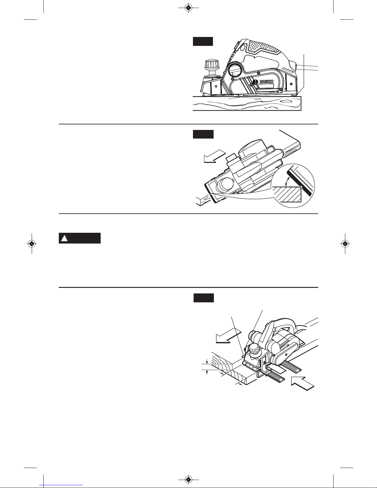
BEVELING EDGES
The V-groove in the front planer base plate
allow quick and easy beveling of workpiece
edges. (Fig. 13).
RABBETING
Although all of the compatible Bosch planer
guide fences can be used with the PL2632 for
rabbeting (sometimes called "shiplapping"), the
best fence for this purpose is the optional dualmount fence.
The PL2632 can create rabbets up to 82 mm /
3-1/2" wide. (Fig. 14). Keep in mind that it
takes steady sideways pressure and many
passes to create rabbets using a planer.
RABBETING DEPTH STOP
The optional rabbeting depth stop (Fig. 14)
allows the user to set any rabbeting depth from
0 to 5/16" (9 mm). For best results, it is
important that the blade be properly aligned
(See "BLADE ALIGNMENT").
Setting the rabbet depth: Loosen wing knob
and using the depth scale on the rabbeting
depth stop, set the desired rabbet depth.
Securely tighten wing knob (Fig. 14).
FIG. 14
9mm
max.
82mm
ma
x
.
RABBETING
DEPTH STOP
WING
KNOB
-14-
P
LANER STAND
The planer stand automatically springs down
to help keep the blade from coming in
contact with the work surface when planer is
not in use (Fig. 12). The planer stand is
designed to swing up and out of the way by it
itself when the back of the plane crosses the
leading edge of the workpiece (Fig. 10). It will
also swing up when planing begins in the
middle of the work piece (in from the edge of
the work piece).
45°
FIG. 13
FIG. 12
PLANER
STAND
UNCLOGGING THE SHAVINGS
EXHAUST SYSTEM
Remove plug from power
source if it becom es
necessary to manually remove shavings.
The blades are hidden from view and you may
be cut if contacted.
To minimize the possibility of clogging, make
sure:
1. The depth of cut is reasonable for the
material.
2. The feed rate is reasonable for the material.
(See DEPTH OF CUT AND FEED RATE)
3. Unplug the planer and carefully insert a
screwdriver or similar object into the
exhaust port to break up the clog.
!
WARNING
2610035786 PL2632 01-15.qxp_PL2632 1/14/15 9:33 AM Page 14
Service
Pre ventive main t enance
performed by unauthorized
personnel may result in misplacing of
internal wires a nd comp onents whic h
cou l d cause ser i o us hazard. We
recommend that all tool service be performed
by a Bosch Factory Service Center or Autho rized Bosch Service Station.
TOOL LUBRICATION
Your Bosch tool has been properly lubricated
and is ready to use. It is recommended that
tools with gears be regreased with a special
gear lubricant at every brush change.
CARBON BRUSHES
The brushes and commutator in your tool
have been engineered for many hours of
dependable service. To maintain peak
efficiency of the motor, we recommend every
two to six months the brush es be examined.
Only genuine Bosch replace ment brushes
specially designed for your tool should be
used.
BEARINGS
Bearings which become noisy (due to heavy
load or very abrasive material cut ting) should
be replaced at once to avoid overheating or
motor failure.
Cleaning
To avoid accidents always
dis connect the tool from
the power suppl y befor e cleani n g o r
performing any main tenance. The tool may
be cleaned most effectively with compressed
dry air. Always wear safety gog gles when
cleaning tools with compressed air.
Ventilation openings and switch levers must
be kept clean and free of foreign matter. Do
not at tempt to clean by inserting pointed
objects through openings.
Ce rtain clea ning agent s
and solvent s damag e
plastic parts. Some of these are: gasoline,
carbon tetrachlo ride, chlo rinated cleaning
solvents, ammonia and house hold detergents
that contain ammonia.
Clean the planer stand regularly and ensure
that it springs back freely.
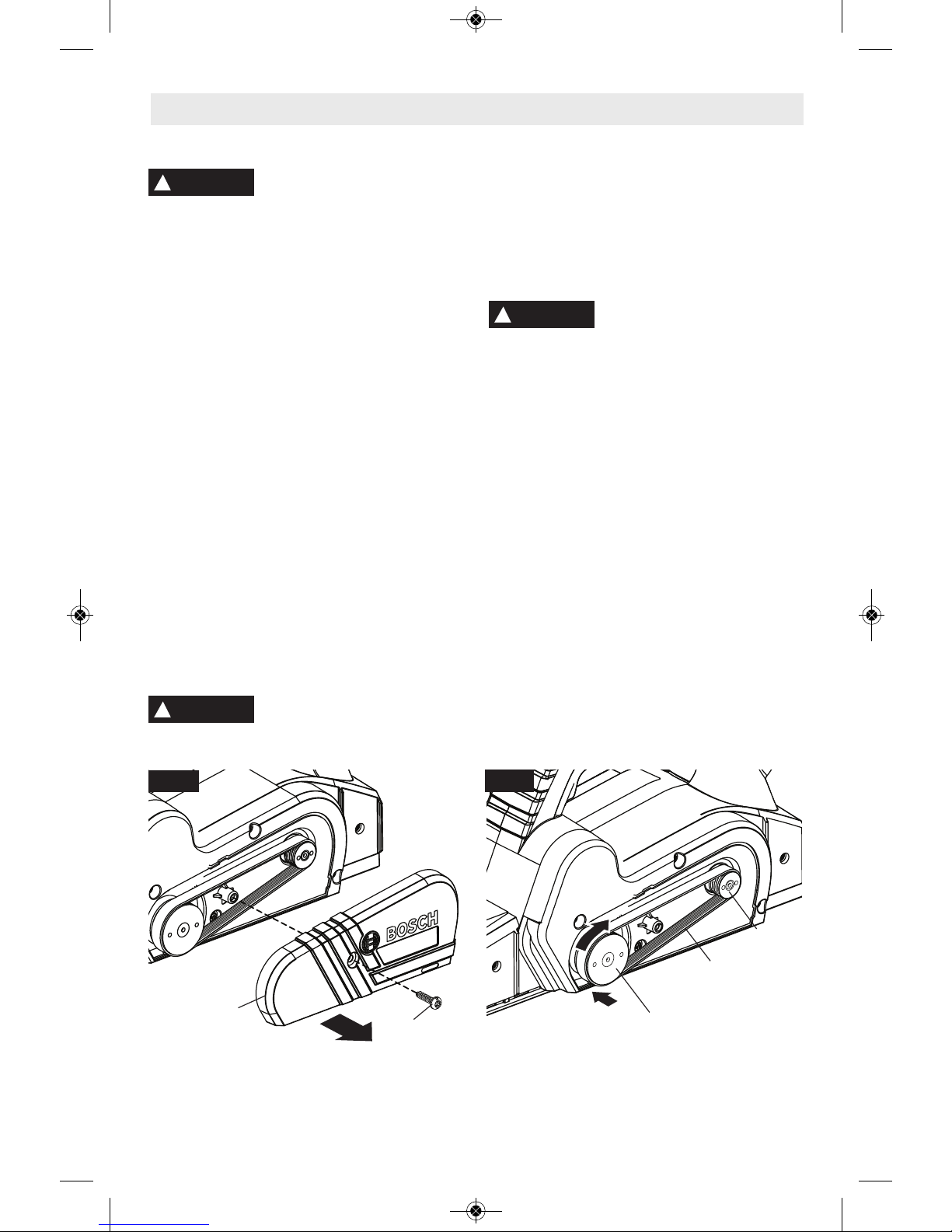
DRIVE BELT
The drive belt is a normal maintenance part
and should be inspected periodically for wear.
If the drive belt shows signs of drying out,
cracking or tearing, it should be replaced. If the
drive belt will not track properly or comes off
the pulleys, it should be replaced.
Installing new drive belt: Loosen screw and
remove the drive belt cover (Fig. 15). Cut and
remove the worn drive belt. Before installing the
new drive belt, clean both pulleys thoroughly.
First place the new drive belt onto the drive
pulley then rotate clockwise while pushing the
belt onto the driven pulley (Fig. 16). Reinstall
the drive belt cover and securely tighten screw
(Fig. 15).
!
WARNING
Maintenance
!
WARNING
!
CAUTION
-15-
FIG. 15
FIG. 16
SCREW
DRIVE BELT
COVER
DRIVEN
PULLEY
DRIVE
PULLEY
DRIVE
BELT
2610035786 PL2632 01-15.qxp_PL2632 1/14/15 9:33 AM Page 15
 Loading...