

Bosch PL1632 Operating/safety Instructions Manual
1-877-BOSCH99 (1-877-267-2499) www.boschtools.com
Operating/Safety Instructions
Consignes d’utilisation/de sécurité
Instrucciones de funcionamiento y seguridad
IMPORTANT
Read Before Using
IMPORTANT
Lire avant usage
IMPORTANTE
Leer antes de usar
For English Version
See page 2
Version française
Voir page 15
Versión en español
Ver la página 30
Call Toll Free for Consumer Information and Service Locations
Pour obtenir des informations et les adresses de nos centres de service après-vente, appelez ce numéro gratuit
Llame gratis para obtener información para el consumidor y ubicaciones de servicio
PL1632
2610052959.qxp_PL1632 7/17/19 9:16 AM Page 1

-2-
Read all safety warnings, instructions, illustrations and specifications
provided with this power tool. Failure to follow all instructions listed
below may result in electric shock, fire and/or serious injury.
SAVE ALL WARNINGS AND INSTRUCTIONS FOR FUTURE REFERENCE
The term “power tool” in the warnings refers to your mains-operated (corded) power
tool or battery-operated (cordless) power tool.
General Power Tool Safety Warnings
Safety Symbols
The definitions below describe the level of severity for each signal word. Please read the
manual and pay attention to these symbols.
!
This is the safety alert symbol. It is used to alert you to
potential personal injury hazards. Obey all safety messages
that follow this symbol to avoid possible injury or death.
DANGER ind icates a haz ardous situat ion which, if no t
avoided, will result in death or serious injury.
WARNING indicates a hazardous situation which, if not
avoided, could result in death or serious injury.
CAUTION indicates a hazardous situatio n w hich, if not
avoided, could result in minor or moderate injury.
▶ Work area safety
Keep work area clean and well lit.
Cluttered or dark areas invite accidents.
Do not operate power tools in explosive
atmospheres, such as in the presence of
flammable liquids, gases or dust. Power
tools create sparks which may ignite the
dust or fumes.
Keep children and bystanders away while
operating a power tool. Distractions can
cause you to lose control.
▶ Electrical safety
Power tool plugs must match the outlet.
Never modify the plug in any way. Do not
use an y adapter pl u g s with earthed
(grounded) power tools. Unmodified plugs
and matching outlets will reduce risk of
electric shock.
Avoid body co n t a c t with earthed or
ground e d surfaces, such as pipes,
radiators, ranges and refrigerators. There
is an increased risk of electric shock if your
body is earthed or grounded.
Do not expose power tools to rain or wet
conditions. Water entering a power tool will
increase the risk of electric shock.
Do not abuse the cord. Never use the cord
for carrying, pulling or unplugging the
power tool. Keep cord away from heat, oil,
sharp edges or moving parts. Damaged or
entangled cords increase the risk of electric
shock.
When operating a power tool outdoors,
use an extension cord suitable for outdoor
use. Use of a cord suitable for outdoor use
reduces the risk of electric shock.
If operating a power tool in a damp
location is unavoidable, use a Ground
Fault Circuit Interrupter (GFCI) protected
supply. Use of an GFCI reduces the risk of
electric shock.
▶ Personal safety
Stay alert, watch what you are doing and
use common sense when op e r a ting a
power tool. Do not use a power tool while
you are tired or under the influence of
drugs, alcohol or medication. A moment of
inattention while operating power tools may
result in serious personal injury.
Use person a l p r o t e c t i v e e q u i p m e n t.
Always wear eye protection. Protective
equipment such as dust mask, non-skid
safety shoes, hard hat, or hearing
2610052959.qxp_PL1632 7/17/19 9:16 AM Page 2

-3-
Safety Rules for Planers
Wait for the cutter to stop before setting
the tool down. An exposed rotating cutter
may engage the surface leading to possible
loss of control and serious injury.
Hold the power tool by insulated gripping
surfaces only, because the cutter may
contact its own cord. Cutting a "live" wire
may make exposed metal parts of the tool
"live" and could give the operator an electric
shock.
Use clamps or another practical way to
secure and support the workpiece to a
stable platform. Holding the workpiece by
your hand or against the body leaves it
unstable and may lead to loss of control.
Always start the planer before blade is in
General Power Tool Safety Warnings
protection used for appropriate conditions
will reduce personal injuries.
Prevent unintentional starting. Ensure the
switch is in the o f f - p o s i t i o n be f o r e
conne c t i n g to p o w e r source a nd / o r
battery pack, picking up or carrying the
tool. Carrying power tools with your finger
on the switch or energizing power tools that
have the switch on invites accidents.
Remov e any a d j u sting key or wrench
before turning the power tool on. A wrench
or a key left attached to a rotating part of
the power tool may result in personal injury.
Do not overreach. Keep proper footing and
balance at all times. This enables better
control of the power tool in unexpected
situations.
Dress properly. Do not wear loose clothing
or jewelry. Keep your hair, clothing and
gloves away from moving parts. Loose
clothes, jewelry or long hair can be caught
in moving parts.
If devices are provided for the connection
of dust extraction and collection facilities,
ensure these are connected and properly
used. Use of dust collection can reduce
dust-related hazards.
Do not let familiarity gained from frequent
use o f tools a l l o w you t o become
compla c e n t and ignore to o l safety
principles. A careless action can cause
severe injury within a fraction of a second.
▶ Power tool use and care
Do not for ce the powe r tool . Use the
correct power tool for your application.
The correc t power too l will do the j ob
better and safer at the rate for which it was
designed.
Do not use the power tool if the switch
does not turn it on and off. Any power tool
that cannot be controlled with the switch is
dangerous and must be repaired.
Discon n e c t th e pl u g fr o m th e po w e r
source and/or remove the battery pack, if
detachable, from the power tool before
making any adjustm e n t s , c h a n g i n g
accessories, or storing power tools. Such
preventive safety measures reduce the risk
of starting the power tool accidentally.
Store idle power tools out of the reach of
childr e n an d do n o t al l o w persons
unfamiliar with the power tool or these
instructions to operate the power tool.
Power tools are dangerous in the hands of
untrained users.
Maintain power tools and accessories.
Ch eck f or misalig nment or bindi ng of
moving parts, breakage of parts and any
other condition that may affect the power
tool’s operation. If damaged, have the
power tool repaired before use. Ma ny
accidents are caused by poorly maintained
power tools.
Keep cutting tools sh a rp and cl e a n .
Properly mainta ined cut ting tools with
sharp cutting edges are less likely to bind
and are easier to control.
Use the power tool, accessories and tool
bits etc. in accordance w i t h th ese
instru c t i o n s , taking i n t o account t h e
working conditions and the work to be
perfor m e d . Use o f the p o w e r tool f o r
operations different from those intended
could result in a hazardous situation.
Keep handles and grasping surfaces dry,
clean a n d free from oil a n d grease.
Slippery handles and grasping surfaces do
not allow for safe handling and control of
the tool in unexpected situations.
▶ Service
Have your po w e r tool se r viced by a
qualified repair person using only identical
replacement parts. This will ensure that the
safety of the power tool is maintained.
2610052959.qxp_PL1632 7/17/19 9:16 AM Page 3

-4-
Additional Safety Warnings
GFCI and personal protection devices like
electrician’s rubber gloves and footwear will
further enhance your personal safety.
Do not use AC only rated tools with a DC
power supply. While the tool may appear to
work, the electrical components of the AC
rated tool are likely to fail and create a
hazard to the operator.
Keep handles dry, clean and free from oil
and grease. Slippery hands cannot safely
control the power tool.
Develop a periodic maintenance schedule
for your tool. When cleaning a tool be
careful not to disassemble any portion of
the t o o l since internal wires m a y be
mi splac ed or pi nched or safety guard
return springs may b e improperly
mounted. Certain cleaning agents such as
gasoline, carbon tetrachloride, ammonia,
etc. may damage plastic parts.
Risk of injury to user. The power cord must
only be serviced by a Bosch Factory Service
Center or Autho rized Bosch Service Station.
Some dust cre ated by
power sanding, sawing,
grinding, drilling, and other construction
activities contains chemicals known to
cause ca n c e r , birth defects or other
reproductive harm. Some examples of
these chemicals are:
• Lead from lead-based paints,
• Crystalline silica from bricks and cement
and other masonry products, and
• Arsenic and chromium from chemically-
treated lumber.
Yo ur r isk from these expos ures varies,
depending on how often you do this type of
work. To reduce your exposure to these
chemicals: work in a well ventilated area,
and work with approved safety equipment,
such as those dust masks that are specially
designed to filter out microscopic particles.
Safety Rules for Planers
contact with the workpiece and allow the
blade to come to full speed. Tool can
vibrate or chatter if blade speed is too slow
at beginning of cut and possibly kickback.
Check the workpiece for nails, if there are
na ils, either rem o ve or set them well
below intended finished surface. If the
planer blades strike objects like nails it may
cause the tool to kickback and serious
personal injury may result.
Unplug th e pl a n e r be f ore c h a n g i n g
accessories. Before plugging the tool in,
chec k that t he trigger lock i s "OFF".
Accidental start-ups may occur if planer is
plugged in while changing an accessory.
After changing blades, rotate the blade
drum to make sure blades are not hitting
any part of the blade head housing and the
blade locking screws are tight. Spinning
blades could st r i ke tool housing an d
damage tool as well as possible injury.
Always hold t he t ool firm ly with both
hands for maximum control.
Never pull the planer backward over the
workpiece. Loss of control may occur.
Do not put fingers or any objects into the
shavin g s exhaust p o r t or c l e a n out
shavings while tool is running. Contact
with blade drum will cause injury.
Rem o v e plug from po w e r source if i t
becomes necessary to remove chips. The
blades are hidden from view and you may
be cut if blade is contacted.
Never use dull or damaged blades. Sharp
blades m u s t be handled with ca r e .
Damaged blades can snap during use. Dull
blades require more force to push the tool,
possibly causing the blade to break.
2610052959.qxp_PL1632 7/17/19 9:16 AM Page 4
-5-
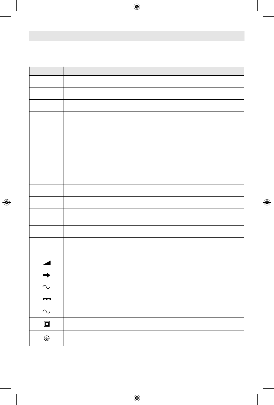
Symbols
Important: Some of the following symbols may be used on your tool. Please study them
and learn their meaning. Proper interpretation of these symbols will allow you to operate
the tool better and safer.
Symbol Designation / Explanation
V Volts (voltage)
Ah Amp hour (measurement of battery capacity)
A Amperes (current)
Hz Hertz (frequency, cycles per second)
W Watt (power)
kg Kilograms (weight)
min Minutes (time)
s Seconds (time)
⌀
Diameter (size of drill bits, grinding wheels, etc.)
n
0
No load speed (rotational speed at no load)
n Rated speed (maximum attainable speed)
.../min
Revolutions or reciprocation per minute (revolutions, strokes, surface
speed, orbits etc. per minute)
0 Off position (zero speed, zero torque...)
1, 2, 3, ...
I, II, III,
Selector settings (speed, torque or position settings. Higher number
means greater speed)
0
Infinitely variable selector with off (speed is increasing from 0 setting)
Arrow (action in the direction of arrow)
Alternating current (type or a characteristic of current)
Direct current (type or a characteristic of current)
Alternating or direct current (type or a characteristic of current)
Class II construction (designates double insulated construction tools)
Earthing terminal (grounding terminal)
2610052959.qxp_PL1632 7/17/19 9:16 AM Page 5

-6-
Important: Some of the following symbols may be used on your tool. Please study them
and learn their meaning. Proper interpretation of these symbols will allow you to operate
the tool better and safer.
Symbols
Symbol Designation / Explanation
Alerts user to read manual
Alerts user to wear eye protection
This symbol designates that this tool is listed by Underwriters
Laboratories.
This symbol designates that this component is recognized by
Underwriters Laboratories.
This symbol designates that this tool is listed by Underwriters
Laboratories, to United States and Canadian Standards.
This symbol designates that this tool is listed by the Canadian
Standards Association.
This symbol designates that this tool is listed by the Canadian
Standards Association, to United States and Canadian Standards.
This symbol designates that this tool is listed by the Intertek Testing
Services, to United States and Canadian Standards.
This symbol designates that this tool complies to NOM Mexican
Standards.
Designates Li-ion battery recycling program
Designates Ni-Cad battery recycling program
2610052959.qxp_PL1632 7/17/19 9:17 AM Page 6
GUIDE
BRACKET
-7-
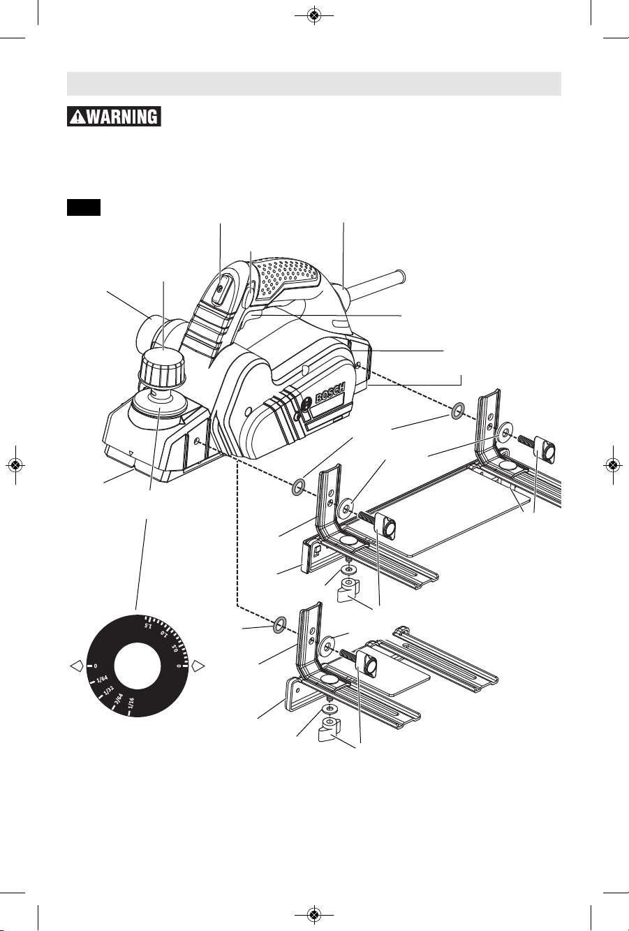
Functional Description and Specifications
Disconnect the plug from the power source before making any
assembly, adjustments or changing accessories. Such preventive safety
measures reduce the risk of starting the tool accidentally.
PL1632 Planer
DEPTH
ADJUSTMENT
KNOB
SHAVINGS
EXHAUST
PORT
GUIDE
BRACKET
FENCE
CHAMFER
V-GROOVE
WASHER
WASHER
WASHER
WASHER
O-RING
O-RING
TRIGGER SWITCH
WRENCH STORAGE AREA
“LOCK-ON”
BUTTON
“LOCK OFF”
BUTTON
BALL-JOINT
CORD SWIVEL
WING KNOBS
WING KNOBS
FENCE
PLANER STAND
DEPTH
SCALE
Maximum Capacities
Planing depth 0 - 1/16" (0 - 1.6mm)
Rabbeting depth 0 - 5/16" (0 - 9mm)
Planing width 3-1/4" (82mm)
NOTE: For tool specifications refer to
the nameplate on your tool.
Dual-Mount
Guide Fence
PA1207
Basic Guide
Fence
WING KNOBS
Fig. 1
2610052959.qxp_PL1632 7/17/19 9:17 AM Page 7

Assembly
-8-
▶ Purposes of Guide Fences
The Bosch planer guide fences all have a
protective shield that covers the unused
section o f the b lade . Therefore, we
recommend always attaching a planer
guide fence (except in situations when
the planing takes place farther in from
the edge of a workpiece than the width
of the planer blade and would interfere
with the work).
All of the Bosch planer guide fences can
be used to control the width of the cut,
such as when creating rabbets (See
page 12).
All of the Bosch planer guide fences also
provide added stability when planing
materials that are up to 3-1/4" wide.
The optional dual-mount guide fence is
especi a l l y h e l p f u l when planing a
vertical edge, such as when planing an
un-mounted door that is laid flat, such
as on saw horses. (Fig. 2)
▶ Positioning of Guide Fences
For right-handed use, the guide fence
should be installed on the left side of
the tool. For left-handed use, the guide
fence should be installed on the right
side of the tool, except when using the
planer to create rabbets, which requires
the guide fence to be installed on the
left side of the tool.
▶ Installation of Basic Guide
Fence
1. Place a wing sc rew through t he
bottom hole in the long end of the
bracket and screw into the front
mount on the appropriate side of the
planer and securely tighten wing
knob. (The O-ring should be on the
backside of the bracket and the flat
washer between the back of the knob
and the front side of the bracket.)
2. Place the bolt through the top of the
hole on the short end of the bracket
and then through the slot in the
appropriate arm of the fence. Place
the flat washer on the bottom of the
bolt below the guide fence’s arm and
then install wing knob. If the washer
is not installed, the guide fence is
likely to slip.
3. Securely tighten wing knob.
▶ Installation of Dual-Mount
Guide Fences
• This is the same as installing the Basic
Guide Fence, except that both brackets
are attached to the planer’s front mount
area and rear mount area (Fig. 1).
▶ Attachment of Plastic
Overshoe to Dual-Mount
Guide Fences
• There are two plastic overshoes that
can be used with the dual-mount
fence, a straight overshoe and 3degree overshoe (sold separately).
• The PA1209 3-degree bevel plastic
overshoe is especially useful when
Fig. 2
PLASTIC
OVERSHOE
DUAL-MOUNT
GUIDE FENCE
TABS (3x)
Fig. 2a
Disconnect the plug from the power source before making any
assembly, adjustments or changing accessories. Such preventive safety
measures reduce the risk of starting the tool accidentally.
2610052959.qxp_PL1632 7/17/19 9:17 AM Page 8
-9-
Assembly
planing the long edges of typical
doors.
• The overshoes clip onto the steel fence.
• To remove either overshoe, gently
pull tabs on overshoe away from the
fence an d then move overshoe
upward (Fig. 2a).
▶ Setting The Desired Planing
Width
1. Loosen the wing knob(s) that hold
the fence onto the brackets guide
bracket(s).
2. Slide the fen ce al ong the gu ide
bracket(s) to the desired planing
width. (When using the dual-mount
fence, it may be necessary to raise
the planer stand before the desired
width can be reached.)
3. Securely tighten wing knobs.
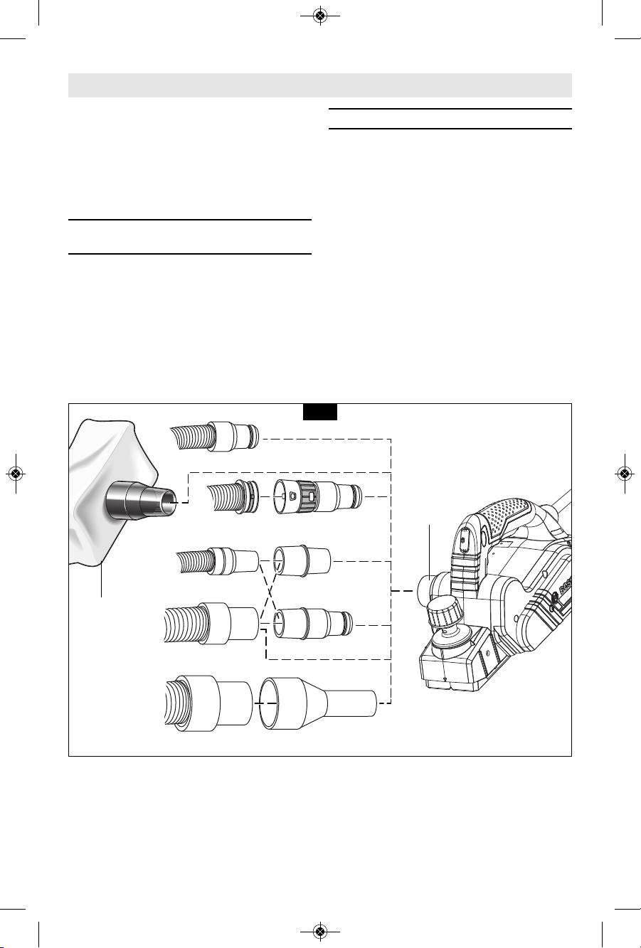
▶ Shavings Extraction
The planer shavings exhaust port may
be used with an optional shavings bag
or a shop vacuum and vacuum
connector (Fig. 3) to keep your work
environment cleaner.
Bosch offers several different vacuum
hoses that will connect these tools to
Bosch vacuum cleaners. The optional
Bosch VAC002 or VAC024 adapters will
connect the planer to 1-1/4” and 1-1/2”
vacuum hoses, and the optional VAC020
will connect the planer to 2-1/2" hoses.
The vacuum cleaner must be suitable
for the material being worked.
When vacuuming dry dust that is
especially detrimental to health or
carcinogenic, use a special vacuum
cleaner / dust extractor.
1¼ hose
35mm hose
Bosch
VH-series hose
VAC002
VX120
VAC024
VAC020
1½ hose
2½ hose
SHAVINGS
BAG
SHAVINGS
EXHAUST
PORT
Fig. 3
2610052959.qxp_PL1632 7/17/19 9:17 AM Page 9

Operating Instructions
-10-
▶ Planer Blades
The planer blades are
sharp and fragile and
must be handled carefully to avoid
injury to the user or damage to the
blades.
Wear protective
gloves when
ch a nging planer blades. Edg e s are
sharp and may cause injury.
Th e PA 1202 Woodra zor m icro-grain
tungsten carbide planer blades have two
cutting edges, and may be reversed
when one of the cutting edges becomes
dull or chipped.
Do n o t attempt to s h a r p e n or us e
resharpened used blades of any kind. Use
only blades designated for use with this
model, because other blades will cause
vibration, decrease performance and may
not clamp securely in blade holder.
▼ REVERSING OR REPLACING
BLADES
To reverse or replace the blade, loosen
the clamping screws with blade wrench.
The wrench is stored on the left side of
the tool (Fig. 1). With the screws
loosened, slide the blade lengthwise out
of the cutter drum, taking care to keep
your fingers away from the sharp edges
of the blade (Fig. 4).
A piece of wood may be used for this
purpose. If the blade is gummed and
difficult to remove, you may clean the
bla d e with mineral s p irits, l a c quer
thinner or alcohol.
Clean all surfaces before reinstalling the
new blade, as this will ensure an
accurate blade setting and proper tool
performance.
▼ BLADE ALIGNMENT
The blade should be centered relative to
the front and rear shoes. (Fig 5.) Rotate
the blade drum by hand to verify sure
that the blade doesn’t touch to any
other part of the tool.
Make sure the blade sits correctly in the
holder groove of the cutter drum.
Yo u may then tig h ten t h e cla m ping
screws which secure the blade and your
planer is ready for use.
2.5 MM
BLADE
WRENCH
CLAMPING
SCREW
CUTTER
DRUM
BLADE
Fig. 4
CLAMPING
SCREW
CUTTER
DRUM
2.5 MM
BLADE
WRENCH
Fig. 5
Assembly
▶ Trigger "ON/OFF" Switch
Hol d the tool wi t h
both ha n ds while
starting the tool, since torque from the
motor can cause the tool to twist.
If the “ L o c k - O N ”
button is
co ntinu ously being depressed, the
trigger cannot be released.
Never l eave the
trigger locked "ON".
Before plugging the tool in, check that
the trigger lock is "OFF". Accidental
start-ups could cause injury.
Be a w are of t h e
location and setting
of the switch "Lock-ON" button. If the
switch is locked "ON" during the use, be
ready for emergency situations to switch
it "OFF".
2610052959.qxp_PL1632 7/17/19 9:17 AM Page 10
TO TURN THE TOOL “ON”: Depress the
“Lock-OFF” button on either side of the
tool and squeeze the trigger switch.
TO TURN THE TOOL “OFF”: Si mply
release the trigger switch.
Your planer is also eq uipped with a
“Lock-ON” button located on the front
of the handle that allows continuous
operation without squeezing the trigger.
TO LOCK THE SWITCH ON: Squeeze
trigger switch fully, depress the “LockON” button and release trigger.
TO UNLOCK THE SWITCH: Squee ze
trigger switch and release it without
depressing the “Lock-ON” button.
▶ Cord Swivel
The swiveling ball joint on the power cord
makes it easy to position the cord in a way
that makes it easier to use the tool (Fig. 1).
▶ Planing Action
Proper planing action helps to achieve
the desired result. With practice and
experi e n c e , it will be c o m e second
nature. Make sure that the workpiece is
held in place securely on your work
surface, and standing comfortably, hold
the planer firmly with both hands.
1. With the planer fully adjusted, place
the front shoe on the workpiece, (be
certain that the blade drum is not in
contact with the work) and start the
planer as described earlier.
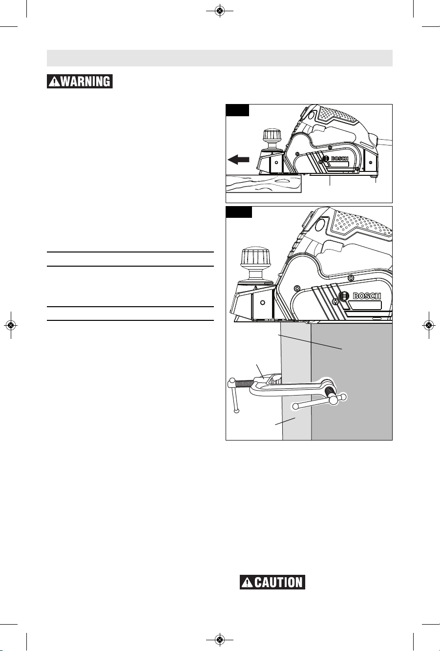
2. With pressure on the front shoe, and
the fence against the side of the work
(to control the width or angle,) feed
the planer steadily until the full length
of the rear shoe passes over the edge
of the workpiece. (Fig. 6)
3. Then gradually transfer pressure to
the rear shoe, and continue planing
to the end of the cut.
4. If pressure is not maintained over
the rear shoe through the end of the
cut, a divot may be created in the
workpiece once the front shoe clear
the end of the workpiec e. To
minimize this possibility, use a 3-way
edge clamp to hold a piece of scrap
wood (at least 1-1/2" (38 mm) thick)
on the end of the workpiece, aligned
with the surface to be planed (Fig.
7). Doing this moves the location of a
potential divot off the workpiece and
on to the piece of scrap wood.
5. Feed the planer at a uniform and
reasonable rate that does not put
excessive strain on the motor or
blades, (do not pull the planer back
over the surface already cut.)
6. Use progressive cuts until you are
near the desired depth, and then readjust to a thin cut for the final pass
to obtain a good surface finish.
The motor may stall
if improperly used or
Operating Instructions
Fig. 7
EDGE
CLAMP
WOOD
SCRAP
WORK PIECE
PLANER
STAND
SHOE
Fig. 6
-11-
Disconnect the plug from the power source before making any
assembly, adjustments or changing accessories. Such preventive safety
measures reduce the risk of starting the tool accidentally.
2610052959.qxp_PL1632 7/17/19 9:17 AM Page 11

overloaded. Reduce the pressure (feed
rate) or depth of cut to prevent possible
damage to the tool if the motor labors.
▶ Depth Of Cut And Feed Rate
The cutting depth (planing depth) is
determined by the difference in height
between the adjustable front shoe and
the fixed rear shoe of the planer. The
de pth k nob a djusts the fro nt sh oe,
which retracts and exposes the blade
and determines the amount of material
remove d from th e workpiece. The
cutting depth range is from 0 to 1/16"
(1.5 mm) per pass. (Fig. 1)
The appropriate depth of cut and feed
rate depends on the workpiece material:
To avoid clogging and/or damage to the
motor, a thinner cut and/or a slower
feed rate may be needed if the material
has an y o f these characteristics:
hardne s s ; gumminess, sappiness,
moisture, paint, varnish and/or knots.
Also, when planing against the grain or
across the grain rather than with the
grain, a shallower cut and/or slower
feed ra t e is required. Whenev e r
possible, test by planing a similar piece
of scrap material.
Use multiple, progressive cuts to
achieve the total desired depth.
Start with a thin cut. If the planer moves
freely through the workpiece with no
excessive load on the motor, the depth
setting can be increased before the next
cut.
When near the desired total depth, readjust the planing depth to a thin
setting for the final cut to obtain a good
surface finish.
Adjusting the Depth of Cut: Rotate
depth ad j u s t m e n t k n o b un t il t h e
indicator is aligned with the desired
cutting depth on the depth scale (Fig.
1).
▶ Planer Stand
The planer stand automatically springs
down t o help ke e p the blade from
coming in contact with the work surface
when planer is not in use (Fig. 8). The
planer stand is designed to swing up
and out of the way by it itself when the
back of the planer crosses the leading
edge of the workpiece (Fig. 6). It will
also swing up when planing begins in
the middle of the work piece (in from
the edge of the work piece).
▶ Beveling Edges
The V-groove in the front planer base
plate allow quick and easy beveling of
workpiece edges. (Fig. 9).
▶Rabbeting
Although all of the compatible Bosch
planer guide fences can be used with
the PL1632 for rabbeting (sometimes
called "shiplapping"), the best fence for
this purpose is the optional dual-mount
fence.
Fig. 10
9mm
max.
8
2
mm
max.
-12-
45°
Fig. 9
Fig. 8
PLANER
STAND
Operating Instructions
2610052959.qxp_PL1632 7/17/19 9:17 AM Page 12
▶ Service
P r e v e n t i v e
m a i n t e n a n c e
performed by unauthorized per so n nel
may result in misplacing of internal
wires and components which could
cause serious hazard. We recommend
that all tool service be performed by a
Bosch Factory Service Center or Autho rized Bosch Service Station.
▶ Tool Lubrication
You r Bosch tool has be e n prope r l y
lubricated and is ready to use. It is
recommended that tools with gears be
regreased with a special gear lubricant
at every brush change.
▶ Carbon Brushes
The brushes and commutator in your
tool have been engineered for many
hours of d e p e ndable se r v ice. To
maintain peak efficiency of the motor,
we recommend every two to six months
the brush es be examined. Only genuine
Bosch replace ment brushes specially
designed for your tool should be used.
▶ Bearings
Bearings which become noisy (due to
heavy load or very abrasive material cut ting) should be repl aced at once to
avoid overheating or motor failure.
▶ Cleaning
Certai n cleaning
agents and sol vents
damage plastic parts. Some of these
are: gasoline, carbon tetrachlo ride, chlo rinated cleaning solvents, ammonia and
hous e h o l d detergen t s that contain
ammonia.
Clean the planer stand regularly and
ensure that it springs back freely.
Ventilation openings and switch levers
must be kept clean and free of foreign
ma tter. Do not at tempt to clean by
insert i n g p o i n t e d objects through
openings.
▶ Drive Belt
The drive belt is a normal maintenance
Maintenance
-13-
The PL1632 can create rabbets up to
82 mm / 3-1/2" wide. (Fig. 10). Keep in
mi n d tha t it take s stea d y sid eways
pressure and many passes to create
rabbets using a planer.
▶ Unclogging the Shavings
Exhaust System
Remove pl u g from
power source if it
become s necessa r y to manually
remove shavings. The blades are hidden
from view and you may be cut i f
contacted.
To minimize the possibility of clogging,
make sure:
1. The depth of cut is reasonable for the
material.
2. The feed rate is reasonable for the
material. (See DEPTH OF CUT AND
FEED RATE)
3. Unplug the planer and carefully insert
a screwdriver or similar object into
the exhaust port to break up the clog.
To avoid accidents, always disconnect the tool and/or charger from the
power supply before servicing or cleaning.
Operating Instructions
Fig. 11
SCREW
DRIVE BELT
COVER
2610052959.qxp_PL1632 7/17/19 9:17 AM Page 13
-14-
part and should be in s p e c t e d
periodically for wear. If the drive belt
shows signs of drying out, cracking or
tearing, it should be replaced. If the
drive belt will not track properly or
co mes o ff t he pu lleys, it sho uld b e
replaced.
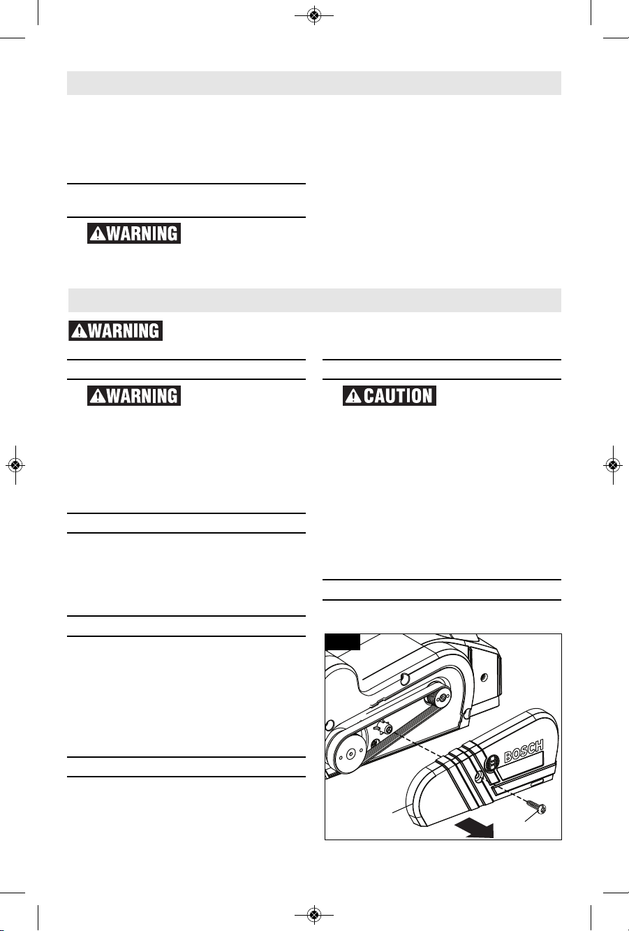
Installing new drive belt: Loosen screw
and remove the drive belt cover (Fig.
11). Cut and remove the worn drive
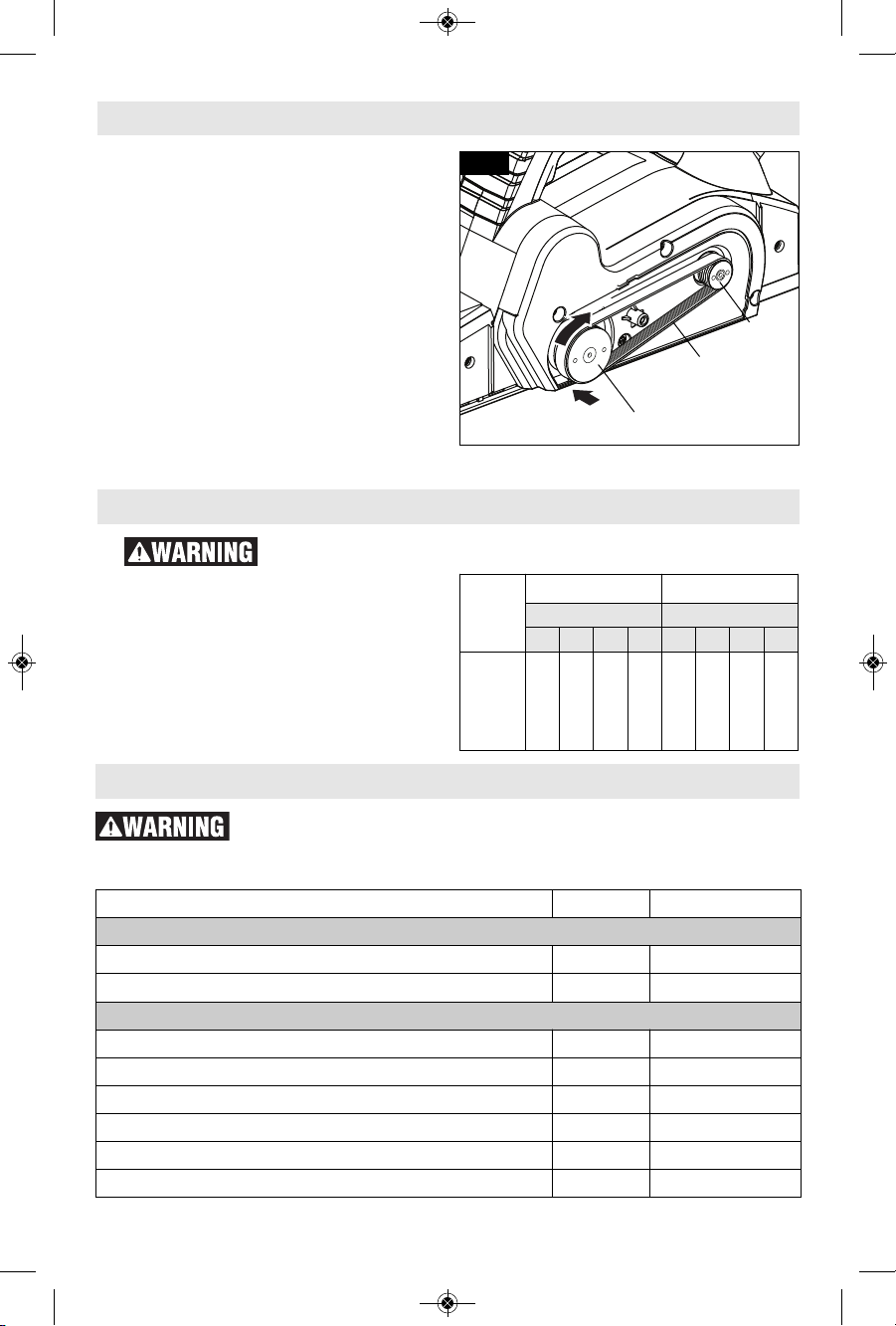
belt. Before installing the new drive
belt, clean both pulleys thoroughly. First
place the new drive belt onto the drive
pulle y then r o t a t e clockwise while
pushing the belt onto the driven pulley
(Fig. 12). Reinstall the drive belt cover
and securely tighten screw (Fig. 11).
Fig. 12
DRIVEN
PULLEY
DRIVE
PULLEY
DRIVE
BELT
If an extension cord
is necessary, a cord
with adequate size conductors that is
capabl e of carrying th e current
necessary for your tool must be used.
This will prevent excessive voltage drop,
loss of power or overheating. Grounded
tools must use 3-wire extension cords
that have 3-prong plugs and receptacles.
NOTE: The smaller the gauge number,
the higher the cord capacity.
RECOMMENDED SIZES OF EXTENSION CORDS
120 VOLT ALTERNATING CURRENT TOOLS
Extension Cords
Accessories and Attachments
Tool’s
Ampere
Rating
Cord Size in A.W.G. Wire Sizes in mm
2
C
ord Length in FeetCord Length in Meters
25 50 100 150 15 30 60 120
3-6
6-8
8-10
10-12
12-16
18
18
18
16
14
16
16
16
16
12
16
14
14
14
–
14
12
12
12
–
0.75
0.75
0.75
1.0
–
0.75
1.0
1.0
2.5
–
1.5
2.5
2.5
4.0
–
2.5
4.0
4.0
–
–
The use of any other attachments or acces so ries not specified in
this manual may create a hazard.
Store accessories in a dry and temperate environment to avoid corrosion and
deterioration.
Description Included Sold Separately
Accessories
Blade wrench 2.5mm ● ●
Woodrazor reversible micro-grain tungsten carbide blade ● ●
Attachments
PA1207 Standard guide fence – ●
Dual-mount guide fence with plastic overshoe – ●
Vacuum hose adapters – ●
Vacuum hoses – ●
Shavings bag – ●
PA1209 3-degree bevel overshoe for dual-mount fence – ●
Maintenance
2610052959.qxp_PL1632 7/17/19 9:17 AM Page 14
-15-
Lisez toutes les co nsignes de sécurité , instructions,
illustrations et spécifications fournies avec cet outil
électrique. Le non-respect de toutes les instructions figurant ci-après pourrait causer un
choc électrique, un incendie et/ou des blessures graves.
CONSERVEZ TOUS LES AVERTISSEMENTS ET TOUTES LES CONSIGNES
DE SÉCURITÉ POUR RÉFÉRENCE FUTURE.
Dans les avertissements, le terme « outil électroportatif » se rapporte à votre outil branché
sur le secteur (avec fil) ou à votre outil alimenté par piles (sans fil).
Avertissements généraux concernant la sécurité des outils électroportatifs
Symboles relatifs à la sécurité
Les définitions ci-dessous décrivent le niveau de gravité pour chaque terme signalant un
danger. Veuillez lire le mode d’emploi et lire la signification de ces symboles.
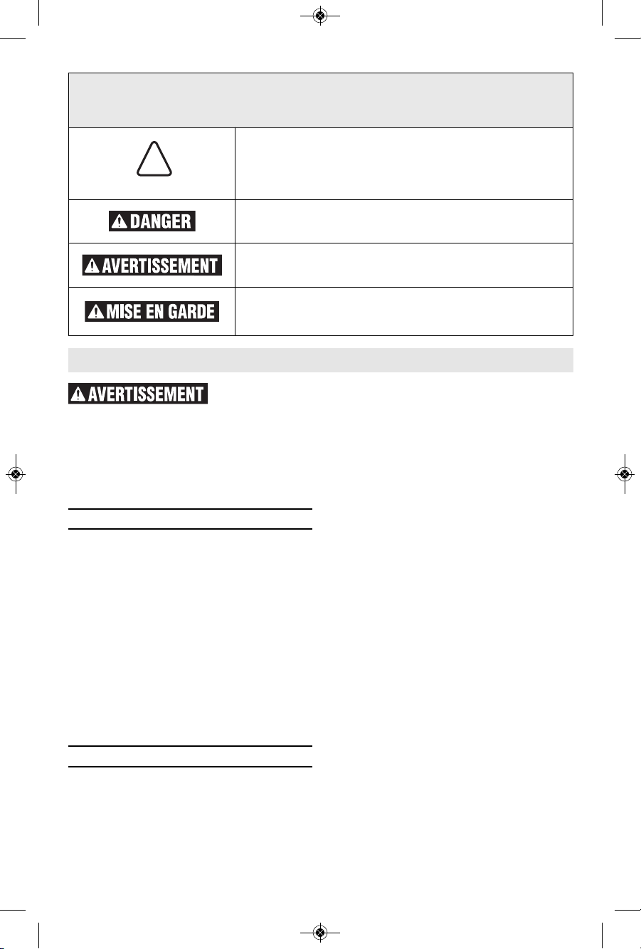
!
C’est le symbole d’alerte relatif à la sécurité. Il est utilisé
pour vous avertir de l’existence possible d’un danger de
lésion corporelle. Obéissez à tous les messages relatifs à la
sécurité qui suivent ce symbole pour éviter tout risque de
blessure ou même de mort.
DANGER indique une situation dangereuse qui, si elle n’est
pas évitée, causera la mort d’une personne ou une blessure
grave.
AVERTISSEMENT indique une situation dangereuse qui, si
elle n’est pas évitée, pourrait causer la mort d’une personne
ou une blessure grave.
MISE EN GARDE indique une situation dangereuse qui, si
elle n'est pas évitée, causera une blessure légère ou
modérée.
▶ Sécurité du lieu de travail
Maintenez le lieu de travail propre et bien
éclairé. Les risques d’accident sont plus
élevés quand on travaille dans un endroit
encombré ou sombre.
N’utilisez pas d’outils électroportatifs dans
des atmosphères explosives, comme par
exempl e e n présence de g a z, de
poussières ou de liquides inflammables.
Les outils électroportatifs produisent des
étincelles qui risquent d’enf lammer les
poussières ou les vapeurs.
Éloignez les enfants et les visiteurs quand
vous vous servez d’un outil électroportatif.
Vous risquez une perte de contrôle si on
vous distrait.
▶ Sécurité électrique
Le s fiche s des outil s élec t roportati f s
doivent correspondre à la prise. Il ne faut
absolu m e n t jamais modifier la fiche.
N’utilisez pas d’adaptateur de prise avec
des outils électroportatifs munis d’une
fiche de terre. Le risque de choc électrique
est moin dre si on utilise une fiche non
modifiée sur une prise qui lui correspond.
Évitez tout contact du corps avec des
surfaces reliées à la terre tels que tuyaux,
radiateurs, gazinières ou réfrigérateurs. Le
risque de choc électrique augmente si votre
corps est relié à la terre.
N’exposez pas les outils électroportatifs à
la pluie ou à l’humidité. Si de l’eau pénètre
dans un outil électroportatif, le risque de
choc électrique augmente.
Ne maltraitez pas le cordon. Ne vous en
se rvez jamai s po ur transpo rter l’out il
électroportatif, pour le tirer ou pour le
débrancher. É loign ez l e cordon de la
chaleur, des huiles, des arêtes coupantes
ou des pièces mobiles. Les cordons abîmés
ou emmêlés augmentent les risques de choc
électrique.
Si vous utilisez un outil électroportatif à
l’extérieur, employez une rallonge conçue
pour l’extérieur. Ces rallonges sont faites
pour l’extérieur et réduisent le risque de
choc électrique.
S'il est absolument nécessaire d'utiliser
l'outi l électr oportatif dans un endroi t
2610052959.qxp_PL1632 7/17/19 9:17 AM Page 15
 Loading...