

Page 1

OBD1110
en User guide
OBDII and CAN Scan Tool
Page 2

2 | Operating instructions | OBD 1110
|
en
|
OBD 1110 | Operating instructions | 3
en
577383 REV A | 10.2015 Bosch Automotive Service Solutions 577383 REV A | 10.2015Bosch Automotive Service Solutions
Table of Contents
Safety Precautions ......... 3
Signal Words and Symbols . 3
Important Safety Messages .. 3
About the Tool ............ 4
Tool Parts ................ 4
Icons .................... 4
Connect the Tool .......... 5
Diagnostic Menu User
Interface ................. 5
Read Codes ............... 6
Vehicle Selection .......... 7
Erase Codes .............. 7
MIL Status ................ 7
I / M Monitors (Emissions) ... 8
View Freeze Data .......... 9
VIN ...................... 9
System Setup ............. 9
View Data ................ 9
Troubleshooting .......... 10
PID Definitions ........... 10
Limited Warranty ......... 15
Disclaimer ............ 15
Software. . . . . . . . . . . . . . 15
Technical Sup port / Repair
Service .............. 15
Declaration of Conformity .. 16
Safety Precautions
This user guide describes the
features of the tool and provides
step-by-step instructions for
operating the tool. Always refer
to and follow safety messages
and test procedures provided by
the manufacturer of the vehicle
and the tool.
Read and understand
the user guide before
operating the tool.
An undetected or uncorrected
vehicle malfunction could cause
a serious, even fatal, accident.
Important safety information in
this user guide is intended to
protect the user, bystanders, and
the vehicle.
Signal Words and Symbols
WARNING!
Indicates a possible
hazardous situation
that, if not avoided,
could result in death
or serious injury to op-
erator or bystanders.
NOTICE
Indicates a condition
that may result in lost
information.
B Indicates a single-
step procedure.
Important Safety
Messages
WARNING!
This tool may not
detect every malfunction. Do not take
chances with brakes,
steering, or other vital
functions of the vehicle. A serious accident
could result.
Always wear ANSIapproved goggles for
eye protection.
• Before testing a vehicle, make
sure the transmission is in
PARK (automatic transmission) or NEUTRAL (manual
transmission) and the parking
brake is set.
• Never lay tools on the vehicle battery.
• Battery acid can burn. If
contacted, rinse with water
or neutralize with a mild
base such as baking soda. If
you splash your eyes, flush
with water and call a physician immediately.
• Never smoke or have open
flames near vehicle. Vapors
from gasoline and battery
are explosive.
Page 3
4 | Operating instructions | OBD 1110
|
en
|
OBD 1110 | Operating instructions | 5
en
577383 REV A | 10.2015 Bosch Automotive Service Solutions 577383 REV A | 10.2015Bosch Automotive Service Solutions
• Do not use the tool if internal
circuitry has been exposed
to moisture. Internal shorts
could cause a fire and damage the vehicle or tool.
• Always turn the ignition
key OFF when connecting
or disconnecting electrical
components unless otherwise instructed.
• Most vehicles are equipped
with airbags. Follow vehicle
service manual precautions.
Serious injury or death
could result from an unintended deployment.
WARNING!
A vehicle airbag can
open for several minutes after the ignition
has been turned off.
• Always follow vehicle manufacturer’s warnings, cautions,
and service procedures.
About the Tool
The tool allows you to retrieve
and erase / reset diagnostic data
from the vehicle control module.
The diagnostic data can be used
to help determine the cause of a
vehicle malfunction.
Use the tool to perform the following functions:
Codes / Data Erase / Reset Retrieve
Confirmed Codes Erase •
Pending Codes Erase •
Permanent Codes — •
View Data — •
MIL Status — •
I / M Monitors Reset •
View Freeze Data Erase •
VIN (Vehicle Identifi
-
cation Number)
— •
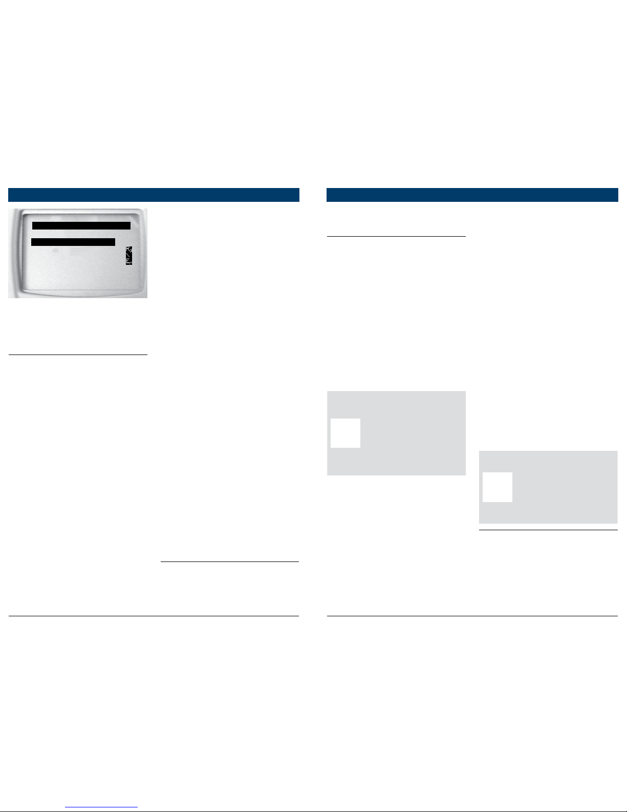
Tool Parts
Part Description
LCD
display
8 line by 21 character mono
-
chrome backlit LCD.
READ
Performs the Read Codes func
tion and scrolls back through
the screens. Press this key when
an up arrow (#) appears on the
display.
ERASE
Performs the Erase Codes func
tion and scrolls forward through
the screens. Press this key when
a down arrow ($) appears on
the display.
ENTER Selects displayed item.
BACK Returns to the previous screen.
OBD II
Connector
Connects the tool to the vehicle
connector.
Icons
Icon Description
$
Indicates additional informa
tion is available on next screen
by using the ERASE key.
#
Indicates additional information
is available on previous screen
by using the READ key.
CONFIRMED
Confirmed codes are reported
when a component is indicat
-
ing a malfunction is present.
PENDING
Pending codes are reported
when a problem occurs during
the current or last completed
drive cycle.
PERMANENT
Permanent codes are a special
type of confirmed code that
only the vehicle can erase.
x / y
Appears only when view
ing codes. Indicates code sequence and quantity (code x
of y). For example, “2 / 9” indi
cates that the 2nd of 9 codes
reported by the computer mod
-
ule is being viewed.
ABS $##
Mod $##
Appears only when viewing
codes. Indicates the computer
module that reported the code.
ABS will appear if the code is
an ABS code. Mod $## appears
when the code is a powertrain
code. The Mod $## is the name
assigned to the vehicle control
module reporting the code.
Indicates that the READ and
ERASE hot keys are active
Connect the Tool
To connect the tool to the vehicle:
1. Locate the OBD II connector
under the steering column. If
the connector is not there, a
label should be there indicating the whereabouts of the
connector. For more information on OBD II connectors, go
to http://www.obdclearinghouse.com/oemdb.
2. If necessary, remove the cover
from the vehicle connector.
3. Turn the ignition switch to
the ON position. Do not start
the engine.
4. Plug the OBDII connector
attached to the tool into the
vehicle connector.
The Tool automatically reads
Codes and displays the data.
When done viewing data,
press
ENTER key to return
to Diagnostic Menu.
NOTICE
If the vehicle returns a
manufacturer specific
code, the tool will ask
if you wish to select
the vehicle and then
read ABS codes.
If the vehicle doesn’t
return a manufacturer
specific code, the tool
will ask if you wish
to select a vehicle to
read ABS codes. ABS
is not supported for
all vehicles.
Diagnostic Menu User
Interface
To select functions:
1. From the Diagnostic Menu,
press the
READ or ERASE
arrow key until the desired
function is highlighted, then
press
ENTER to retrieve and
display the results.
Page 4
6 | Operating instructions | OBD 1110
|
en
|
OBD 1110 | Operating instructions | 7
en
577383 REV A | 10.2015 Bosch Automotive Service Solutions 577383 REV A | 10.2015Bosch Automotive Service Solutions
manufacturer specific DTC is
retrieved from the vehicle.
Erase Codes
The Erase function performs
the following:
9 Erases codes (both
Confirmed and Pending
DTCs) when erasing OBDII/
EOBD codes. Permanent
codes can only be erased by
the vehicle.
9 May erase Freeze Data results
depending on the vehcle.
9 Sets I / M Monitors to
not ready.
NOTICE
Perform Erase Codes
function only after
systems have been
checked completely
and DTCs have been
written down.
To erase codes from the vehicle computer:
1. Set the ignition to Key On
Engine Off. Do NOT start the
vehicle. The engine should
not be running.
2. Press and hold the ERASE
key for 3 seconds then
release, or select Erase
Codes from Diagnostic Menu;
press
ENTER.
3. When the confirmation message appears on the display,
choose one of the following options.
• To proceed with the opera-
tion: Press
ENTER for YES.
• To cancel the operation and
return to the Diagnostic
Menu: Press BACK for NO.
4. If ABS is supported for your
vehicle, a menu is shown to
select either OBDII/EOBD,
or ABS. Select ABS to erase
ABS codes, and OBDII/EOBD
to erase emissions related
powertrain codes.
The Tool will automatically perform the Read Codes function
after erasing codes. The Tool
will then indicate the number of
codes remaining.
NOTICE
If after erasing codes
a DTC returns, the
problem has not been
fixed or other faults
are present.
MIL Status
MIL (Malfunction Indicator
Lamp) status indicates if the
vehicle computer is telling the
MIL to illuminate when the
engine is running.
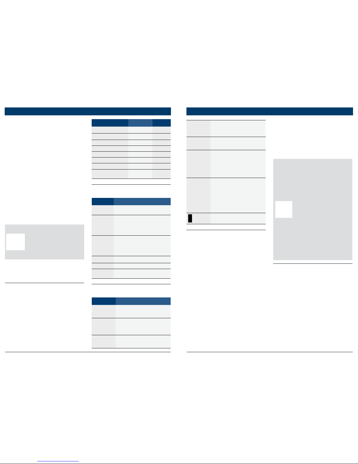
DIAGNOSTIC MENU
====================
Read Codes
Erase Codes
MIL Status
View Data
View Freeze Data
^^
VIN
2. When complete, press
BACK to return to the
Diagnostic Menu selection screen.
Read Codes
To read the codes:
B Press and hold the
READ key for 2 sec-
onds then release it, or
Select Read Codes from
Diagnostic Menu.
If ABS is supported for your vehicle, a menu is shown to select
either OBDII/EOBD, or ABS.
Select ABS to read ABS codes,
and OBDII/EOBD to read emissions related powertrain codes.
For codes other than ABS codes,
the tool displays Confirmed,
Pending, and Permanent Codes.
Confirmed Trouble Codes are
reported when a component,
sensor, or other part of the
vehicle is indicating a malfunction is present. The malfunction
must be present for a sufficient
amount of time before the vehicle records and the Tool displays
a Confirmed Trouble Code.
Confirmed codes are indicated
by the CONFIRMED icon.
Pending Codes are only reported
if a problem occurs during the
current or last completed drive
cycle. Pending Codes do not necessarily indicate a faulty component or system. Pending Codes
convert to Confirmed Trouble
Codes when an emissions problem persists long enough to be
considered a real problem, not
an anomaly. Pending Codes are
indicated by a PENDING icon.
Permanent Codes are special
confirmed codes. Permanent
Codes began being reported by
vehicles beginning around 2010,
so they are not supported by
every vehicle. While Confirmed
Codes can be erased by the
tool, Permanent Codes cannot.
Permanent Codes are erased by
the vehicle when the vehicle has
determined the fault is no longer
present. Permanent Codes are
indicated by a PERMANENT icon.
Vehicle Selection
Vehicle Selection will be displayed for Read Codes when a
Page 5

8 | Operating instructions | OBD 1110
|
en
|
OBD 1110 | Operating instructions | 9
en
577383 REV A | 10.2015 Bosch Automotive Service Solutions 577383 REV A | 10.2015Bosch Automotive Service Solutions
Since DTCs Cleared - shows
status of the monitors since
the DTCs were last erased.
This Drive Cycle - shows
status of monitors since the
start of the current drive
cycle. Refer to the vehicle
service manual for more
detailed information on
emission-related monitors
and their status.
9 Some vehicles do not sup-
port This Drive Cycle. If
vehicle supports both types
of monitors the I / M Monitors
Menu displays.
View Freeze Data
Displays a snapshot of operating conditions at the time the
Diagnostic Trouble Code was
created. See PID Definitions for
more information.
VIN
The VIN function allows the
tool to request the vehicle’s
VIN number.
The VIN function applies to
model year 2000 and newer OBD
II compliant vehicles.
System Setup
System Setup allows:
• Display contrast to
be changed
• Tool information to be viewed
• Display to be checked
• Operation of the keypad to
be checked
• Memory of the Tool to
be checked
• Units of measure to
be changed
View Data
The View Data function allows
real time viewing of the vehicle’s
computer module’s PID data.
As the computer monitors the
vehicle, information is simultaneously transmitted to the Tool.
View Data allows the following
items to be viewed on the Tool:
Sensor data
Operation of switches
Operation of solenoids
Operation of relays
Multiple PIDs may be sent if vehicle is equipped with more than
one computer module (for example a powertrain control module [PCM] and a transmission
control module [TCM]. The Tool
identifies them by their identification names (ID) assigned
by manufacturer (i.e. $10 or
$1A). See PID Definitions for
more information.
• MIL ON indicates that the
Malfunction Indicator Lamp
should be ON.
• MIL OFF indicates that the
Malfunction Indicator Lamp
should be OFF.
I / M Monitors (Emissions)
Inspection / Maintenance
Monitors provide a snapshot
of the Emission System operations by indicating that the
I / M Monitors are Ready or Not
Ready. For an I / M Monitor to
be Ready, the vehicle must have
completed a drive cycle (been
driven long enough under proper
conditions to have completed a
drive cycle). A Monitor must be
listed as Ready to pass an emissions test. If an I / M Monitor is
Not Ready, it is because a drive
cycle has not completed.
The Tool will indicate Ready
(ok), Not Ready (inc), or Not
Applicable (n/a) for each I / M
Monitor. The Tool supports the
following I / M Monitors:
Monitor Expanded Name
Misfire Monitor Misfire Monitor
Fuel System Mon Fuel System Monitor
Comp Component
Comprehensive Compo
-
nents Monitor
Catalyst Mon Catalyst Monitor
Htd Catalyst Heated Catalyst Monitor
Evap System Mon
Evaporative System Mon
-
itor
Sec Air System
Secondary Air System
Monitor
A/C Refrig Mon
Air Conditioning Refriger
-
ant Monitor
Oxygen Sens Mon Oxygen Sensor Monitor
Oxygen Sens Htr
Oxygen Sensor Heater
Monitor
EGR/VVT Sys Mon
Exhaust Gas Recircula
tion or Variable Valve Timing Monitor
NMHC Cat Mon
Non-Methane Hydrocar
-
bon Catalyst
NOX Treat Mon Nitrogen Oxide Treatment
Boost Pres Mon Boost Pressure Monitor
Exhst Gas Sensr Exhaust Gas Sensor
PM Filter Mon Particulate Matter Filter
This is a complete list of I / M
Monitors supported by the Tool.
The number of Monitors read
by the Tool from your vehicle
may vary. A diesel vehicle, for
example, does not have an
Oxygen Sensor Monitor. As a
result, there will be no Oxygen
Sensor Monitor status for a diesel vehicle.
Two types of I / M Monitors
tests are:
Page 6

10 | Operating instructions | OBD 1110
|
en
|
OBD 1110 | Operating instructions | 11
en
577383 REV A | 10.2015 Bosch Automotive Service Solutions 577383 REV A | 10.2015Bosch Automotive Service Solutions
PID PID description
AECD8_
TIME1, TIME 2
Total Run Time with EI-AECD
#8 Timer 1 Active, #2 Timer
Active
AECD9_
TIME1, TIME 2
Total Run Time with EI-AECD
#9 Timer 1 Active, #2 Timer
Active
ALCOHOL Alcohol Fuel Percent
BARO PRS Barometric Pressure
BAT_PWR
Hybrid Battery Pack Remain
-
ing Life
BP_A_ACT, B_
ACT
Boost Pressure Sensor A, Sen
-
sor B
BP_A_CMD,
B_CMD
Commanded Boost Pressure
A, Pressure B
BP_A_STAT, B_
STAT
Boost Pressure A Control Sta
-
tus, B Control Status
CACT 11, 12
Charge Air Cooler Temper
ature Bank 1 Sensor 1 supported, Sensor 2 supported
CACT 21,22
Charge Air Cooler Temper
ature Bank 2 Sensor 1 supported, Sensor 2 supported
CALC LOAD Calculated Engine Load
CAT TEMP11,
TEMP12
Cataltic Converter Temp
Bank1, Temp Bank 3
CAT TEMP21,
TEMP22
Cataltic Converter Temp
Bank2, Temp Bank 4
CLR DIST Distance since erase
CLR TIME Minutes Run since Erase
CLR TRPS Warmups Since Erase
CMD EQ RAT
Commanded Equivalence
Ratio
COOLANT Engine Coolant Temp
DPF_REG_
AVGD
Average Distance Between
DPF Regen
DPF_REG_
AVGT
Average Time Between DPF
Regen
DPF_REG_
STAT
Diesel Particulate Filter (DPF)
Regen Status
DPF_REG_TYP
Diesel Particulate Filter (DPF)
Regen Type
DPF_REGEN_
PCT
Normalized Trigger for DPF
Regen
PID PID description
DPF1_DP,
DPF2_DP
Diesel Particulate Filter (DPF)
Bank 1 Delta Pressure Bank 2
Delta Pressure
DPF1_INP,
DPF2_INP
Diesel Particulate Filter (DPF)
Bank 1 Inlet Pressure, Bank 2
Inlet Pressure
DPF1_INT,
DPF2_INT
DPF Bank 1 Inlet Temperature
Sensor, Bank 2 Inlet Tempera
-
ture Sensor
DPF1_OUTP,
DPF2_OUTP
Diesel Particulate Filter (DPF)
Bank 1 Outlet Pressure,
Bank 2 Outlet Pressure
DPF1_OUTT,
DPF2_OUTT
DPF Bank 1 Outlet Temper
ature Sensor, Bank 2 Outlet
Temperature Sensor
ECT 1, 2
Engine Coolant Temperature
1, Temperature 2
EGR CMD Comanded EGR
EGR ERR
Exhaust Gas Recirculation
Error
EGR_A_ACT,
B_ACT
Actual EGR A Duty Cycle / Posi
-
tion, B Duty Cycle / Position
EGR_A_CMD,
B_CMD
Commanded EGR A Duty
Cycle / Position, B Duty Cycle /
Position
EGR_A_ERR,
B_ERR
EGR A Error, B Error
EGRT 11, 21
Exhaust Gas Recirculation
Temperature Bank 1 Sensor 1,
Bank 2 Sensor 1
EGRT 12, 22
Exhaust Gas Recirculation
Temperature Bank 1 Sensor 2,
Bank 2 Sensor 2
EGT 11, 21
Exhaust Gas Temperature
(EGT) Bank 1 Sensor 1, Bank
2 Sensor 1
EGT 12, 22
Exhaust Gas Temperature
(EGT) Bank 1 Sensor 2, Bank
2 Sensor 2
EGT 13, 23
Exhaust Gas Temperature
(EGT) Bank 1 Sensor 3, Bank
2 Sensor 3
EGT 14, 24
Exhaust Gas Temperature
(EGT) Bank 1 Sensor 4, Bank
2 Sensor 4
EMIS_SUP
Emission requirements to
which vehicle is designed
ENG RUN Time Since Engine Start
Troubleshooting
If a “LINK ERROR” message
appears, cycle the ignition
key to the OFF position for
10 seconds, then back ON,
then press the
ENTER
key. Make sure the ignition
key is in the ON not the
ACCESSORY position.
If the MIL Status is ON and
the MIL is not illuminated
with the engine running,
then a problem exists in the
MIL circuit.
PID Definitions
NOTICE
Although over 300
PIDS are available,
the tool only displays
the PIDs the vehicle
supports.
PID PID description
ABS FRP Absolute Fuel Rail Pressure
ABS LOAD Absolute Load Value
ABS TPS B, C Throttle Position B, C
ABSLT TPS Absolute Throttle Position
ACC POS D Accelerator Pedal D, E, F
ACC POS REL
Relative Accelerator Pedal
Position
AECD1_TI
-
ME1, TIME 2
Total Run Time with EI-AECD
#1 Timer 1 Active, #2 Timer
Active
AECD10_TI
-
ME1, TIME 2
Total Run Time with EI-AECD
#10 Timer 1 Active, #2 Timer
Active
PID PID description
AECD11_TI
-
ME1, TIME 2
Total Run Time with EI-AECD
#11 Timer 1 active, #2 Timer
Active
AECD12_TI
-
ME1, TIME 2
Total Run Time with EI-AECD
#12 Timer 1 active, #2 Timer
Active
AECD13_TI
-
ME1, TIME 2
Total Run Time with EI-AECD
#13 Timer 1 active, #2 Timer
Active
AECD14_TI
-
ME1, TIME 2
Total Run Time with EI-AECD
#14 Timer 1 active, #2 Timer
Active
AECD15_TI
-
ME1, TIME 2
Total Run Time with EI-AECD
#15 Timer 1 active, #2 Timer
Active
AECD16_TI
-
ME1, TIME 2
Total Run Time with EI-AECD
#16 Timer 1 active, #2 Timer
Active
AECD17_TI
-
ME1, TIME 2
Total Run Time with EI-AECD
#17 Timer 1 active, #2 Timer
Active
AECD18_TI
-
ME1, TIME 2
Total Run Time with EI-AECD
#18 Timer 1 active, #2 Timer
Active
AECD19_
TIME1, TIME 2
Total Run Time with EI-AECD
#19 Timer 1 active, #2 Timer
Active
AECD2_
TIME1, TIME 2
Total Run Time with EI-AECD
#2 Timer 1 Active, #2 Timer
Active
AECD20_
TIME1, TIME 2
Total Run Time with EI-AECD
#20 Timer 1 active, #2 Timer
Active
AECD3_
TIME1, TIME 2
Total Run Time with EI-AECD
#3 Timer 1 Active, #2 Timer
Active
AECD4_
TIME1, TIME 2
Total Run Time with EI-AECD
#4 Timer 1 Active, #2 Timer
Active
AECD5_
TIME1, TIME 2
Total Run Time with EI-AECD
#5 Timer 1 Active, #2 Timer
Active
AECD6_
TIME1, TIME 2
Total Run Time with EI-AECD
#6 Timer 1 Active, #2 Timer
Active
AECD7_
TIME1, TIME 2
Total Run Time with EI-AECD
#7 Timer 1 Active, #2 Timer
Active
Page 7

12 | Operating instructions | OBD 1110
|
en
|
OBD 1110 | Operating instructions | 13
en
577383 REV A | 10.2015 Bosch Automotive Service Solutions 577383 REV A | 10.2015Bosch Automotive Service Solutions
PID PID description
O2S12_PCT,
O2S22_PCT
02 Sensor Concentration
Bank 1 Sensor 2, Bank 2 Sen
-
sor 2
OBD2 STAT OBD Status
OUT TEMP Ambient Air Temp
PM 11, PM 21
PM Sensor Mass Concentra
tion Bank 1 Sensor 1, Bank 2
Sensor 1
PNTE_Stat PM NTE control area status
PTO STATUS PTO Status
PTO_STAT Power Take Off (PTO) Status
PTO_TIME
Total Run Time With PTO
Active
REAG_DEMD
Average Demanded Reagent
Consumption
REAG_LVL Reagent Tank Level
REAG_RATE Average Reagent Consumption
REL FRP Relative Fuel Rail Pressure
REL TPS Relative Throttle Position
RUN_TIME Total Engine Run Time
SCR REAG
DEV, DEV1,
DEV2, DEV3,
DEV4
SCR inducement system
actual state 10K history DEV1
(0 - 10000 km), 10K history
DEV2 (10000 - 20000 km),
10K history DEV3 (20000 30000 km), 10K history DEV4
(30000 - 40000 km): deviation
of reagent consumption
SCR REAG
LOW, LOW1,
LOW2, LOW3,
LOW4
SCR inducement system
actual state 10K history LOW1
(0 - 10000 km), 10K history
LOW2 (10000 - 20000 km),
10K history LOW3 (20000 30000 km), 10K history LOW4
(30000 - 40000 km): reagent
level too low
SCR RE
AG WRONG,
WRONG1,
WRONG2,
WRONG3,
WRONG4
SCR inducement system
actual state 10K history
WRONG1 (0 - 10000 km), 10K
history WRONG2 (10000 20000 km), 10K history
WRONG3 (20000 - 30000 km),
10K history WRONG4 (30000 40000 km): incorrect reagent
SCR SYS AC
-
TIVE
SCR inducement system
actual state: inducement sys
-
tem active
PID PID description
SCR_DIST_1D
Distance travelled in current
10K block (0 - 10000 km)
SCR_DIST_1N,
2N, 3N, 4N
Distance travelled while
inducement system active
in current 10K block 1N
(0 - 10000 km), 20K block 2N
(10 - 20000 km), 30K block 3N
(20 - 30000 km), 40K block 4N
(30 - 40000 km)
SECOND AIR Secondary Air Status
ST FTRM Fuel Trim Bank / Sensor
ST FTRM1, 3 Shor t Term Fuel Trim1 or 3
ST FTRM2, 4 Shor t Term Fuel Trim2 or 4
ST SEC
FT1, 2, 3, 4
Short Term Secondary O2
Sensor Fuel Trim 1, 2, 3, 4
TAC_A_CMD,
B_CMD
Commanded Throttle Actuator
A Control, B Control
TAC_A_REL,
B_REL
Relative Throttle A Position,
B Position
TCA_CINP,
TCB_CINP
Turbocharger Compressor
Inlet Pressure Sensor A, Pres
-
sure Sensor B
TCA_CINT,
TCB_CINT
Turbocharger A Compres
sor Inlet Temperature, Turbocharger B
TCA_COUT,
TCB_COUT
Turbocharger A Compressor
Outlet Temperature, Turbo
-
charger B
TCA_RPM,
TCB_RPM
Turbocharger A RPM, B RPM
TCA_TCOUT,
TCB_TCOUT
Turbocharger A Turbine Outlet
Temperature, Turbocharger B
TCA_TINT,
TCB_TINT
Turbocharger A Turbine Inlet
Temperature, Turbocharger B
THROT CMD
Commanded Throttle Actua
-
tor Control
TP G Absolute Throttle Position G
TQ_ACT Actual Engine - Percent Torque
TQ_DD
Driver's Demand Engine - Per
-
cent Torque
TQ_MAX1, 2,
3, 4, 5
Engine Percent Torque At
Point 1 (Idle), Point 2, 3, 4, 5
TQ_REF Engine Reference Torque
TROUB CODE
Code causing the Freeze
Frame
PID PID description
ENG SPEED Engine RPM
EOT Engine Oil Temperature
EP_1, 2
Exhaust Pressure Sensor Bank
1, Bank 2
EQ RATIO Equivalence Ratio
EVAP PURGE Commanded EVAP Purge
EVAP VP EVAP Vapor Pressure
EVAP VPA Absolute EVAP Vapor Pressure
FRP_A, B Fuel Rail Pressure A, B
FRP_A_CMD,
B_CMD
Commanded Fuel Rail Pres
-
sure A, B
FRT_A, B Fuel Rail Temperature A , B
FUEL LEVEL Fuel Level Input
FUEL PRES Fuel Rail Pressure
FUEL SYS 1, 2
Fuel System 1 Loop Status,
System 2 Loop Status
FUEL TYPE Fuel Type
FUEL_RATE Engine Fuel Rate
FUEL_TIMING Fueling Injection Timing
GPL_STAT Glow Plug Lamp Status
IAF_A_CMD,
B_CMD
Commanded Intake Air Flow A
Control, B Control
IAF_A_REL, B_
REL
Relative Intake Air Flow A
Position, B Position
IAT Intake Air Temp
IAT 11, 21
Intake Air Temperature Sen
sor Bank 1 Sensor 1, Bank 2
Sensor 1
IAT 12, 22
Intake Air Temperature Sen
sor Bank 1 Sensor 2, Bank 2
Sensor 2
IAT 13, 23
Intake Air Temperature Sen
sor Bank 1 Sensor 3, Bank 2
Sensor 3
ICP_A, B
Injection Control Pressure
A, B
ICP_A_CMD,
B_CMD
Commanded Injection Control
Pressure A, B
IDLE_TIME Total Idle Run Time
IGN ADV Timing Advance
PID PID description
LAMBDA11, 2102 Sensor Lambda Bank 1
Sensor 1, Bank 2 Sensor 1
LAMBDA12, 2202 Sensor Lambda Bank 1
Sensor 2, Bank 2 Sensor 2
LT FTRM1 Long Term Fuel Trim 1 or 3
LT FTRM2 Long Term Fuel Trim 2 or 4
LT SEC FT1,
2, 3, 4
Long Term Secondary O2 Sen
-
sor Fuel Trim 1, 2, 3, 4
MAF, A, B Mass Air Flow, A, B
MAP, A, B
Manifold Absolute Pressure,
A, B
MIL DIST MIL_DIST
MIL STATUS Malfunction Indicator Lamp
MIL TIME Minutes Run by MIL activated
MST Manifold Surface Temperature
N/D_STAT
Auto Trans Neutral Drive
Status
N/G_STAT
Manual Trans Neutral Gear
Status
NNTE_Stat NOx NTE control area status
NOX 11, 21
NOx Sensor Concentration
Bank 1 Sensor 1, Bank 2 Sen
-
sor 1
NOX 12,22
NOx Sensor Concentration
Bank 1 Sensor 2, Bank 2 Sen
-
sor 2
NOX LEVEL
HI, HI1, HI2,
HI3, HI4
SCR inducement system
actual state 10K history HI1
(0-10000 km), 10K history HI2
(10000-20000 km), 10K his
tory HI3 20000-30000 km),
10K history HI4 (3000040000 km): NOx emission
too high
NOX_ADS_DE
-
SUL
NOx Adsorber Desulfuriza
-
tion Status
NOX_ADS_RE
-
GEN
NOx Adsorber Regen Status
NWI_TIME
Total Run Time by the Engien
whicle NOx warning mode is
activated
O2S
O2 Voltage or Current indi
-
cates Bank / Sensor
O2S11_PCT,
O2S21_PCT
02 Sensor Concentration
Bank 1 Sensor 1, Bank 2 Sen
-
sor 1
Page 8

14 | Operating instructions | OBD 1110
|
en
|
OBD 1110 | Operating instructions | 15
en
577383 REV A | 10.2015 Bosch Automotive Service Solutions 577383 REV A | 10.2015Bosch Automotive Service Solutions
Limited Warranty
This warranty is expressly limited to original retail buyers
of Bosch electronic diagnostic
tools (“Units”).
Bosch Units are warranted against
defects in materials and workmanship for one year (12 months)
from date of delivery. This warranty does not cover any Unit that
has been abused, altered, used
for a purpose other than that for
which it was intended, or used
in a manner inconsistent with
instructions regarding use. The
sole and exclusive remedy for
any Unit found to be defective is
repair or replacement, the option
of Bosch. In no event shall Bosch
be liable for any direct, indirect,
special, incidental or consequential damages (including lost profit)
whether based on warranty,
contract, tort or any other legal
theory. The existence of a defect
shall be determined by Bosch
in accordance with procedures
established by Bosch. No one is
authorized to make any statement
or representation altering the
terms of this warranty.
Disclaimer
The above warranty is in lieu of
any other warranty, express or
implied, including any warranty
of merchantability or fitness for a
particular purpose.
Software
Unit software is proprietary,
confidential information protected
under copyright law. Users have
no right in or title to Unit software
other than a limited right of use
revocable by Bosch. Unit software may not be transferred or
disclosed without written consent
of Bosch. Unit software may not
be copied except in ordinary
backup procedures.
Technical Support /
Repair Service
If you have any questions on
the operation of the product,
please call 1300 783 031 or
email automotive.
techsupport@au.bosch.com.
Please contact Technical Suppor t
for troubleshooting and service
options prior to sending any unit
for repair.
For repair, return the unit to point
of purchase.
PID PID description
VEH SPEED Vehicle Speed
VGT_A_ACT,
B_ACT
Variable Geometry Turbo A
Position, Turbo B
VGT_A_CMD,
B_CMD
Commanded Variable Geome
-
try Turbo A Position, Turbo B
VGT_A_STAT,
B_ STAT
Variable Geometry Turbo A
Control Status, Turbo B
VPWR Control Module Voltage
WG_A_ACT, B_
ACT
Wastegate A Position, B
Position
WG_A_CMD,
B_CMD
Commanded Wastegate A
Control, B Control
TQ_DD Driver's demand engine per
-
cent torque
TQ_ACT Actual engine percent torque
TQ_MAX1,
MAX2, MAX3,
MAX4, MAX5
Engine percent torque at
idle point 1, 2, 3, 4, 5
TQ_REF Engine reference torque
VGT_A_ACT Variable geometry turbo A
position
VGT_A_CMD Commanded variable geome
-
try turbo A position
VGT_A_STAT Variable geometry turbo A con
-
trol status
VGT_B_ACT Variable geometry turbo B
position
VGT_B_CMD Commanded variable geome
-
try turbo B position
VGT_B_STAT Variable geometry turbo B con
-
trol status
VPWR Control module voltage
WG_A_ACT Wastegate A position
WG_A_CMD Commanded wastegate A
control
WG_B_ACT Wastegate B position
WG_B_CMD Commanded wastegate B
control
Page 9

16 | Operating instructions | OBD 1110
|
en
|
OBD 1110 | Operating instructions | 17
en
577383 REV A | 10.2015 Bosch Automotive Service Solutions 577383 REV A | 10.2015Bosch Automotive Service Solutions
Declaration of Conformity Notes
Substance Maximum Concentration
Cadmium (Cd) 100 ppm
Hexavalent Chromium (CrVI) 1000 ppm
Lead (Pb) 1000 ppm
Mercury (Hg) 1000 ppm
Polybrominated Biphenyls (PBB) 1000 ppm
Polybrominated Diphenyl Ethers (PBDE) 1000 ppm
This product is declared to conform to the following standard under
the EMC directive 2004/108/EC.
EN 61326-1:2013
This product is declared to be in compliance with the
European RoHS Directive 2011/65/EU which restricts the
following substances in electrical and electronic equipment:
Disposal Information
This product should be disposed of separately from household waste. When the product reaches its end of life, dispose of it according to
local laws and regulations.
Matthew Koran
Hardware Development Manager
Automotive Service Solutions
Brook Park, Ohio, USA
October 1, 2015
Page 10

18 | Operating instructions | OBD 1110
|
en
|
OBD 1110 | Operating instructions | 19
en
577383 REV A | 10.2015 Bosch Automotive Service Solutions 577383 REV A | 10.2015Bosch Automotive Service Solutions
NotesNotes
Page 11

©Bosch Automotive Service Solutions
300 Wellington Rd
Mulgrave, VIC 3170
Australia
1300 783 031
www boschdiytools com.au
 Loading...