

Page 1

OBD1000
PocketScan™ Code Reader
en User guide
es Guía del usuario
fr Mode d‘emploi
Page 2

Page 3

English
Safety Precautions ...................... 4
Signal Words and Symbols ............ 4
Important Safety Messages ............... 5
Tool Parts ............................. 6
PocketScan™ Code Reader Features ........ 6
Read Codes ........................ 6
MIL Conditions ...................... 6
Inspection/Maintenance Monitors (I/M
Monitors ........................... 7
Reading Diagnostic Trouble Codes and Data .. 7
Erasing Diagnostic Trouble Codes and Data .. 9
Diagnostic Trouble Codes ................ 10
Code Structure ..................... 11
Powertrain Codes ................... 11
Chassis Codes ..................... 11
Body Codes ....................... 11
Network Communication Codes ........ 11
Code Descriptions .................. 11
Limited Warranty ...................... 28
Disclaimer of Warranty ............... 28
Limitation of Remedies .............. 28
To Use Your Warranty ............... 28
Out of Warranty Repair. . . . . . . . . . . . . . . 28
Español
Precauciones de Seguridad .............. 29
Palabras destacadas ................ 29
Mensajes Importantes de Seguridad ....... 30
Piezas de Herramientas ................. 31
Características del Lector de Códigos Pocket-
Scan ................................. 32
Leer Códigos ...................... 32
Condiciones MIL .................... 32
Monitores de Inspección y Mantenimiento
(Monitores de I/M) .................. 33
Lectura de Códigos Diagnósticos de Problemas
y otros datos .......................... 33
Borrado de Códigos Diagnósticos de Problemas
y otros datos .......................... 35
Códigos Diagnósticos de Problemas (DTC) .. 37
Estructura de Código ................ 38
Códigos del Tren de Potencia .......... 38
Códigos del Chasis .................. 38
Códigos de la Carrocería ............. 38
Códigos de Comunicación de la Red .... 38
Descripciónesde los Códigos ............38
Garantía Limitada Completa .............. 58
Cláusula de exención de responsabilidad 58
Limitación de recursos ............... 58
Para utilizar su garantía .............. 58
Reparación fuera de garantía ......... 58
Français
Mesures de Sécurité .................... 59
Mots Clés Utilisés .................. 59
Messages de Sécurité Importants ......... 60
Pièces d‘outils ......................... 61
Caractéristiques du lecteur de codes Pocket-
Scan™ ............................... 61
Codes lus ......................... 61
Conditions MIL ..................... 61
Contrôles d‘inspection et maintenance (I/M
Monitors) ......................... 62
Lecture des Codes de Diagnostic de Défauts et
des Données .......................... 63
Effacement des codes et données de diagnostic
de défauts ............................ 65
Codes de diagnostic de défauts (DTC) ..... 66
Structure du Code .................. 67
Codes du groupe motopropulseur ...... 67
Codes châssis ...................... 67
Codes carrosserie .................. 67
Codes communication réseau ......... 68
Descriptions des Codes .............. 68
Garantie Limitée ....................... 88
Stipulation d’exonération de garantie ... 88
Limitation des recours ............... 88
Pour bénéficier de votre garantie ....... 88
Réparation hors garantie ............. 88
Page 4

4 | User guide | OBD 1000
|
en
574694 REV A | 11.2014 Bosch Automotive Service Solutions
Safety Precautions
For safety, read, understand and follow all
safety messages and
instruction in manual before operating the Pock-
etScan™ Code Reader.
Always refer to and follow safety
messages and test procedures
provided by manufacturer of vehicle
and PocketScan Code Reader.
Signal Words and Symbols
DANGER!
Indicates a possible hazardous situation that, if
not avoided, will result in
death or serious injury to
operator or bystanders.
WARNING!
Indicates a possible hazardous situation that, if
not avoided, could result
in death or serious injury
to operator or bystanders.
CAUTION!
Indicates a possible hazardous situation that, if
not avoided, may result in
moderate or minor injury
to operator or bystanders.
IMPORTANT
Indicates a condition that
may result in damage to
test equipment or vehicle
or lost information.
Page 5

|
OBD 1000 | User guide | 5
en
574694 REV A | 11.2014Bosch Automotive Service Solutions
Important Safety Messages
Always wear ANSI-approved goggles for eye
protection.
• Always operate vehicle in a
well-ventilated area.
• Always keep people, tools, and
test equipment away from all
moving or hot engine parts.
• Before testing a vehicle, make
sure the transmission is in PARK
(automatic transmission) or
NEUTRAL (manual transmission)
and the parking brake is set.
• Always block drive wheels and
never leave vehicle unattended
while testing.
• Always keep a fire extinguisher
suitable for gasoline/electrical/
chemical fires redily available.
• Never lay tools on the vehicle
battery.
• Always use caution when working around ignition coil, distributor cap, ignition wires, and spark
plugs. Components can produce
a High Voltage while engine is
running.
• Battery acid is caustic. If contacted, rinse with water or neutralize with a mild base (i.e.
baking soda). If in eyes, flush
with water and call a physician
immediately.
• Never smoke or have open
flames near vehicle. Vapors from
gasoline and battery during
charge are explosive.
• Never use the PocketScanTM
Code Reader if internal circuitry
has been exposed to moisture.
Internal shorts could cause a fire
and damage.
• Always turn ignition key OFF
when connecting or disconnecting electrical components,
unless otherwise instructed.
Some vehicles are equipped with
safety air bags. Follow vehicle service manual cautions when working
around air bag components or
wiring.
WARNING!
A vehicle airbag can open
for several minutes after
the ignition has been
turned off.
• Always follow vehicle manufacturer’s warnings, cautions, and
service procedures.
Page 6
6 | User guide | OBD 1000
|
en
574694 REV A | 11.2014 Bosch Automotive Service Solutions
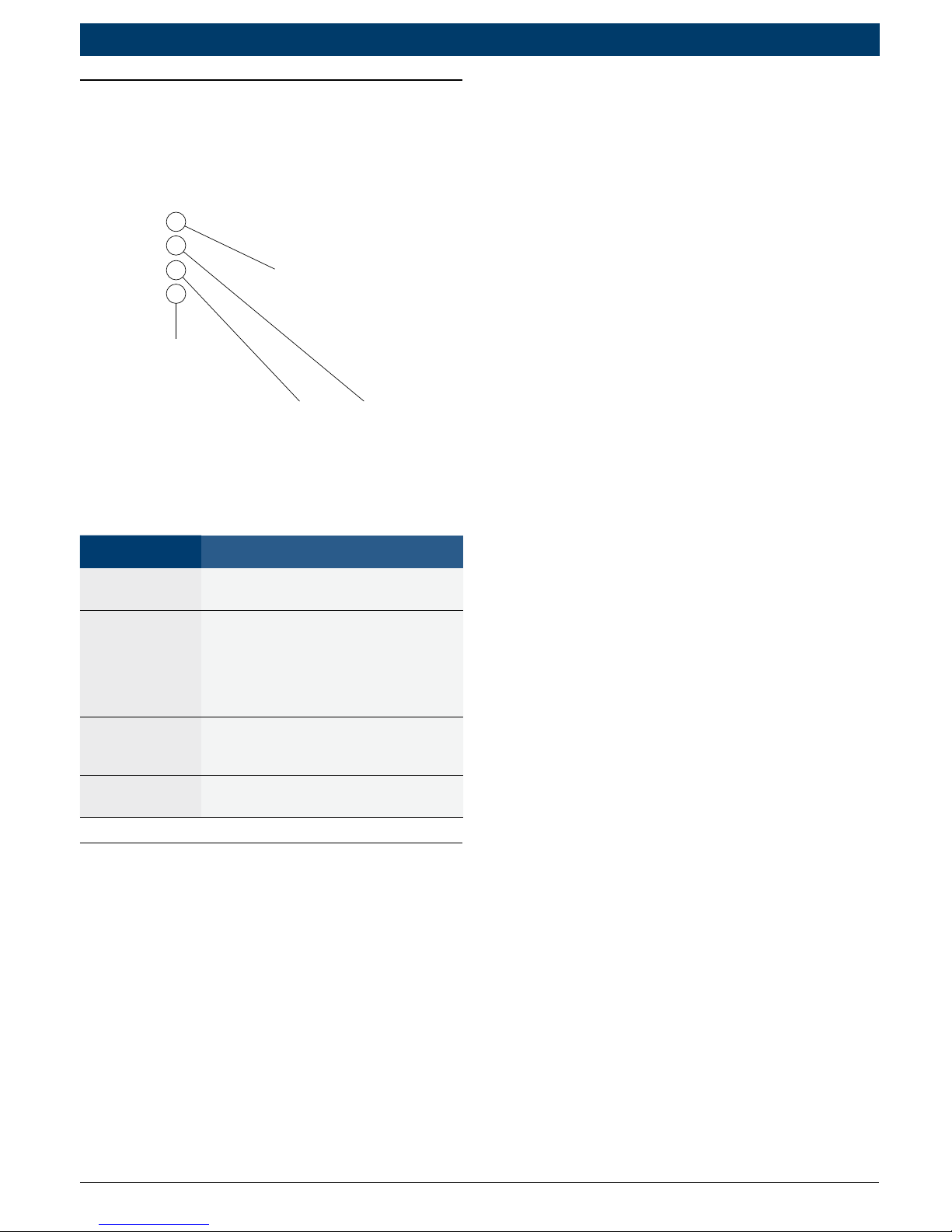
Tool Parts
1
2
3
4
Part Description
1
LCD
display
Single-line display with 8 char
-
acters.
2 ERASE
Used to Erase Trouble Codes and
I/M Monitor status from Vehicle’s
Computer Modules and scroll up
through screens. (I/M Monitors
are currently used for state emis
-
sions tests.)
3 READ
Used to view Read Codes, MIL
Status, I/M Readiness Status and
scroll down through screens.
4
OBD II
Connector
Used to communicate with OBD II
compliant vehicles.
PocketScan™ Code Reader
Features
Read Codes
Reading Diagnostic Trouble Codes
allows the PocketScan
Code Reader to read the codes
from the vehicle’s computer
modules.
• Diagnostic Trouble Codes:
Diagnostic Trouble Codes are
used to help determine the
cause of a problem or problems
with a vehicle. Diagnostic Trouble Codes are set when a fault is
present for a sufficient amount
of time.
• Pending Codes:
Pending Codes are also referred
to as “continuous monitor
codes” and “maturing codes.”
Pending Codes occurs when the
code has not occurred a specific
number of times (depending on
vehicle,) causing the code to
mature.
MIL Conditions
MIL (Malfunction Indicator Lamp)
Status displays the
state of the vehicles computer
module(s).
• MIL ON:
Indicates that the Malfunction
Indicator Lamp on vehicle should
be ON indicating a possible
emissions problem.
9 If the MIL Status is ON and the
MIL is not illuminated with the
engine running, then a problem
exists in the MIL circuit.
• MIL OFF:
Page 7
|
OBD 1000 | User guide | 7
en
574694 REV A | 11.2014Bosch Automotive Service Solutions
Indicates the Malfunction Indicator Lamp should be off and there
should be no emission problems.
9 Some manufacturers will turn
the MIL off if a certain number
of drive cycles occur without the
same fault being detected.
9 Diagnostic Trouble Codes
related to a MIL are erased from
the computer’s memory after 40
warm-up cycles if the same fault
is not detected.
Inspection/Maintenance Monitors
(I/M Monitors
The I/M Monitors (Inspection /
Maintenance) function displays a
SNAPSHOT of the operations for the
Emission System.
9 After a specific amount of drive
time (each monitor has specific
driving conditions and time
required), the computer’s “monitors” will decide if the vehicles
emission system is working
correctly.
9 Some states MAY NOT require all
monitors listed to be “Ready” to
pass the emissions test. Check
with state testing site for exact
requirements. All states will fail
a vehicle that has the “MIL
Light” lit at time of test.
• Monitors Viewed:
Monitor Expanded Name
Misfire Misfire monitor
Fuel Fuel system monitor
Comp Comprehensive components monitor
Catlyst Catalyst monitor
Htd Cat Heated catalyst monitor
Evap Evaporative system monitor
Sec Air Secondary air system monitor
A/C Air conditioning refrigerant monitor
O2 Snsr Oxygen sensor monitor
O2 Htr Oxygen sensor heater monitor
EGR Exhaust gas recirculation
• Monitor Status:
Status Description
Ready
Vehicle was driven enough under proper
conditions to complete the monitor.
Inc
(Incomplete) Vehicle was not driven
enough under proper conditions to com
-
plete the monitor.
• Monitors may be cleared by:
• Using the erase codes func-
tion.
• Disconnected or discharged
battery (on some vehicles.)
• Computer module losing
power (on some vehicles.)
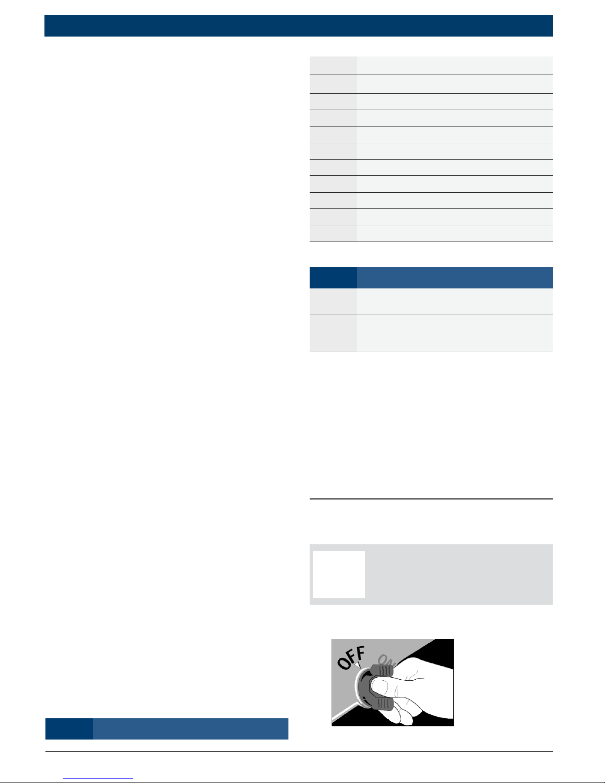
Reading Diagnostic Trouble
Codes and Data
WARNING!
Avoid cooling fan. Fan
may turn on during test.
1. Turn ignition key to the OFF
position.
Page 8
8 | User guide | OBD 1000
|
en
574694 REV A | 11.2014 Bosch Automotive Service Solutions
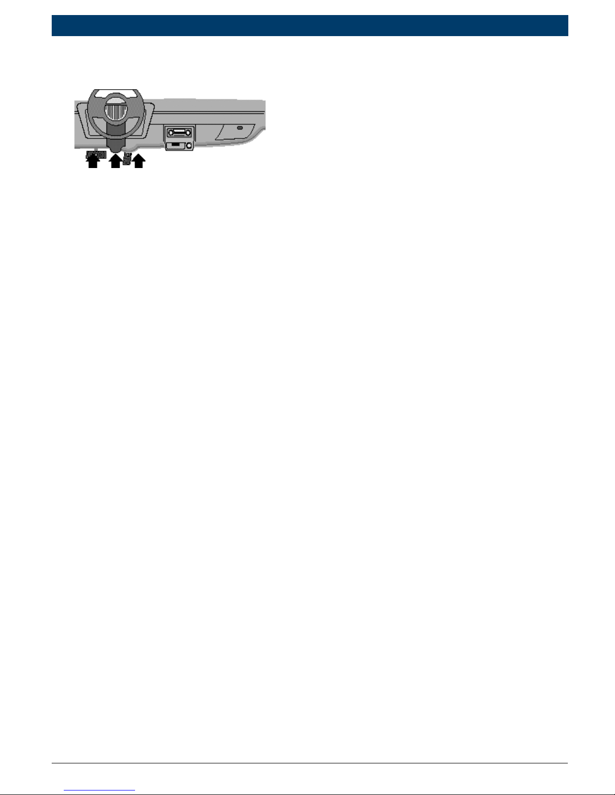
2. Locate and plug in data link
connector (DLC).
NOTE: The data link connector
should be located under the
dashboard on the driverside of
the vehicle. If the data link connector is not located under the
dashboard as stated, a label
describing the location of the
data link connector should be
there.
3. Observe display toggles between
“Pocket” and “Scan”.
NOTE: For a correct reading for
diagnostic trouble codes and I/M
monitor status, ignition key must
be in the ON position and engine
does not require starting. To get
a correct reading for MIL status,
engine must be started.
4. Start engine.
5. Press and release
key.
NOTE: If diagnostice trouble
codes (DTCs) are already being
displayed from a previous read
operation, press and hold
for 3 seconds and release.
6. Observe a moving * on display.
NOTE: If “No Link” message
displays, cycle ignition key to the
OFF position for 10 seconds,
then back ON and repeat “Reading Diagnostic Data” procedure.
7. View codes on display.
NOTE: If
there are no codes present, the
tool will display “0 Codes” and
proceed to display MIL Status
when
is pressed.
• To view codes, press and
release
.
• If the code is a pending code,
pd will be displayed.
8. View MIL status:
• Press and release
.
9. View I/M monitors that are
incomplete.
• Press and release
.
Page 9
|
OBD 1000 | User guide | 9
en
574694 REV A | 11.2014Bosch Automotive Service Solutions
NOTE: If there are no more
I/M monitors that are incomplete, the tool will then
display ready monitors when
is pressed.
10. View I/M monitors that are
ready.
• Press and release
.
NOTE: Pressing
will
scroll up to review diagnostic
trouble codes and data.
Holding
down for 3
seconds will read diagnostic
trouble codes and data again.
Erasing Diagnostic Trouble
Codes and Data
Erasing allows the PocketScan™
code reader to delete the codes and
IM monitor status from the vehicle’s
computer modules.
NOTICE
Only erase diagnostic data
after checking
system completely and
writing down results.
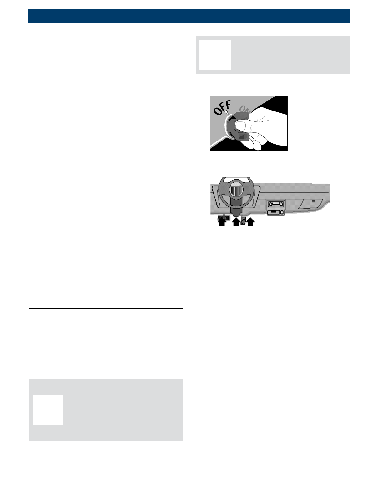
WARNING!
Avoid cooling fan. Fan
may turn on during test.
1. Turn ignition key to the OFF
position.
2. Locate and plug in data link
connector (DLC).
NOTE: The data link connector
should be located under the
dashboard on the driverside of
the vehicle. If the data link
connector is not located under
the dashboard as stated, a label
describing the location of the
data link connector should be
there.
3. Observe display toggles between
“Pocket” and “Scan”.
4. Turn ignition key to the ON
position leaving engine off.
NOTE: Make sure that the ignition key is ON and NOT in the
accessory position.
Page 10

10 | User guide | OBD 1000
|
en
574694 REV A | 11.2014 Bosch Automotive Service Solutions
5. Press and hold for 3 seconds and release.
6. Observe “ERASE?” displays.
7. Press and hold for 3 seconds and release.
8. Observe a moving — on display.
NOTE: If a “NO LINK” message
displays, cycle ignition key to the
OFF position for 10 seconds,
then back ON, and repeat “Erasing Diagnostic Data” procedure.
9. Observe “DONE” displays.
NOTE: If the problem causing
diagnostic trouble code(s) still
exists, the code will return. The
diagnostic trouble code may
return immediately or may
return after vehicle has been
driven.
NOTE: Pressing
will read
diagnostic trouble codes and
data and holding will erase
results again.
Diagnostic Trouble Codes
This section contains the J2012
Diagnostic Trouble Codes (DTCs) as
defined by the Society of Automotive
Engineers (SAE).
DTCs are recommendations not a
requirement. Manufacturers may not
follow these, but most do.
Check vehicle’s service manual for
DTC meaning if the code(s) you are
getting does not make sense.
DTC definitions have been assigned
or reserved by the Society of Automotive Engineers (SAE) to direct to
proper service area(s).
Codes not assigned or reserved by
the SAE are reserved for the manufacturer and referred to as Manufacturer Specific DTCs.
Remember:
• Visual inspections are important!
• Problems with wiring and connec-
tors are common, especially for
intermittent faults.
• Mechanical problems (vacuum
leaks, binding or sticking linkages,
etc.) can make a good sensor look
bad to the computer.
• Incorrect information from a
sensor may cause the computer
to control the engine in the
wrong way. Faulty engine operation might even make the com-
Page 11
|
OBD 1000 | User guide | 11
en
574694 REV A | 11.2014Bosch Automotive Service Solutions
puter show a known good sensor as being bad!
Code Structure
1. Bx = Body
Cx = Chassis
Px = Powertrain
Ux = Network comm.
x - 0, 1, 2, or 3
2. Vehicle specific system
3. Specific fault designation
Example:
P0101 - Mass or volume air flow
cir cuit range/performance problem
Powertrain Codes
Code Type
P0xxx Generic (SAE)
P1xxx Manufacturer specific
P2xxx Generic (SAE)
P30xx–P33xx Manufacturer specific
P34xx–P39xx Generic (SAE)
Chassis Codes
Code Type
C0xxx Generic (SAE)
C1xxx Manufacturer specific
C2xxx Manufacturer specific
C3xxx Generic (SAE)
Body Codes
Code Type
B0xxx Generic (SAE)
B1xxx Manufacturer specific
B2xxx Manufacturer specific
B3xxx Generic (SAE)
Network Communication Codes
Code Type
U0xxx Generic (SAE)
U1xxx Manufacturer specific
U2xxx Manufacturer specific
U3xxx Generic (SAE)
Code Descriptions
Code Description
P0001 Fuel Volume Regulator Control Circuit/
Open
P0002 Fuel Volume Regulator Control CKT
Range/Perf
P0003 Fuel Volume Regulator Control Circuit
Low
P0004 Fuel Volume Regulator Control Circuit
High
P0005 Fuel Shutoff Vlv. A Control Circuit/Open
P0006 Fuel Shutoff Vlv. A Control Circuit Low
P0007 Fuel Shutoff Vlv. A Control Circuit High
P0008 Engine Position System Performance
(Bank 1)
P0009 Engine Position System Performance
(Bank 2)
P0010 Camshaft Position Actuator A - Bank 1
Circuit Malfunction
P0011 Camshaft Position Actuator A - Bank 1
Timing Over-Advan.
P0012 Camshaft Position Actuator A - Bank 1
Timing Over-Retard
P0013 Camshaft Position Actuator B - Bank 1
Circuit Malfunction
P0014 Camshaft Position Actuator B - Bank 1
Timing Over-Advan.
P0015 Camshaft Position Actuator B - Bank 1
Timing Over-Retard
P0016 Cam/Crankshaft Pos. Correlation Sensor
A - Bank 1
P0017 Cam/Crankshaft Pos. Correlation Sensor
B - Bank 1
P0018 Cam/Crankshaft Pos. Correlation Sensor
A - Bank 2
P0019 Cam/Crankshaft Pos. Correlation Sensor
B - Bank 2
P0020 Camshaft Position Actuator A - Bank 2
Circuit Malfunction
P0021 Camshaft Position Actuator A - Bank 2
Timing Over-Advan.
Page 12

12 | User guide | OBD 1000
|
en
574694 REV A | 11.2014 Bosch Automotive Service Solutions
P0022 Camshaft Position Actuator A - Bank 2
Timing Over-Retard
P0023 Camshaft Position Actuator B - Bank 2
Circuit Malfunction
P0024 Camshaft Position Actuator B - Bank 2
Timing Over-Advan.
P0025 Camshaft Position Actuator B - Bank 2
Timing Over-Retard
P0026 Intake Valve-Bank 1 Control Solenoid CKT
Range/Perf
P0027 Exhaust Valve-Bank1 Control Solenoid
CKT Range/Perf
P0028 Intake Valve-Bank 2 Control Solenoid CKT
Range/Perf
P0029 Exhaust Valve-Bank2 Control Solenoid
CKT Range/Perf
P0030 HO2S Bank 1 Sen 1 Heater Circuit
P0031 HO2S Bank 1 Sen 1 Heater Circuit Low
P0032 HO2S Bank 1 Sen 1 Heater Circuit High
P0033 Turbo/Sup Wastegate Control Circuit
P0034 Turbo/Sup Wastegate Control Circuit Low
P0035 Turbo/Sup Wastegate Control Circuit
High
P0036 HO2S Bank 1 Sen 2 Heater Circuit
P0037 HO2S Bank 1 Sen 2 Heater Circuit Low
P0038 HO2S Bank 1 Sen 2 Heater Circuit High
P0039 Turbo/Super Charger Bypass Cntrl CKT
Performance
P0040 O2 Bank 1 Sensor 1 Signals Swapped w/
O2 Bank 2 Sensor 1
P0041 O2 Bank 1 Sensor 2 Signals Swapped w/
O2 Bank 2 Sensor 2
P0042 HO2S Bank 1 Sen 3 Heater Circuit
P0043 HO2S Bank 1 Sen 3 Heater Circuit Low
P0044 HO2S Bank 1 Sen 3 Heater Circuit High
P0045 Turbo/Super Boost Ctrl Solenoid A Cir
-
cuit/Open
P0046 Turbo/Super Boost Ctrl Solenoid A CKT
Range/Perf
P0047 Turbo/Super Boost Ctrl Solenoid A Cir
-
cuit Low
P0048 Turbo/Super Boost Ctrl Solenoid A Cir
-
cuit High
P0049 Turbo/Super Boost Input/Turbine Speed
Overspeed
P0050 HO2S Bank 2 Sen 1 Heater Circuit
P0051 HO2S Bank 2 Sen 1 Heater Circuit Low
P0052 HO2S Bank 2 Sen 1 Heater Circuit High
P0053 HO2S Bank 1 Sen 1 Heater Resistance
P0054 HO2S Bank 1 Sen 2 Heater Resistance
P0055 HO2S Bank 1 Sen 3 Heater Resistance
P0056 HO2S Bank 2 Sen 2 Heater Circuit
P0057 HO2S Bank 2 Sen 2 Heater Circuit Low
P0058 HO2S Bank 2 Sen 2 Heater Circuit High
P0059 HO2S Bank 2 Sen 1 Heater Resistance
P0060 HO2S Bank 2 Sen 2 Heater Resistance
P0061 HO2S Bank 2 Sen 3 Heater Resistance
P0062 HO2S Bank 2 Sen 3 Heater Circuit
P0063 HO2S Bank 2 Sen 3 Heater Circuit Low
P0064 HO2S Bank 2 Sen 3 Heater Circuit High
P0065 Air Assisted Injec. Control Range/Per
-
formance
P0066 Air Assisted Injec. Control Circuit Low
P0067 Air Assisted Injec. Control Circuit High
P0068 MAF/MAP Sensor Throttle Position Cor
-
relation
P0069 MAP/BARO Correlation
P0070 Ambient Air Temp. Sensor Circuit
P0071 Ambient Air Temp. Sensor Range/Per
-
formance
P0072 Ambient Air Temp. Sensor Circuit Low
P0073 Ambient Air Temp. Sensor Circuit High
P0074 Ambient Air Temp. Sensor CKT Inter
-
mittent
P0075 Intake Valve-Bank 1 Control Circuit
P0076 Intake Valve-Bank 1 Control Circuit Low
P0077 Intake Valve-Bank 1 Control Circuit High
P0078 Exhaust Valve-Bank1 Control Circuit
P0079 Exhaust Valve-Bank1 Control Circuit Low
P0080 Exhaust Valve-Bank1 Control Circuit High
P0081 Intake Valve-Bank 2 Control Circuit
P0082 Intake Valve-Bank 2 Control Circuit Low
P0083 Intake Valve-Bank 2 Control Circuit High
P0084 Exhaust Valve-Bank2 Control Circuit
P0085 Exhaust Valve-Bank2 Control Circuit Low
P0086 Exhaust Valve-Bank2 Control Circuit High
P0087 Fuel Rail Pressure Too Low
P0088 Fuel Rail Pressure Too High
P0089 Fuel Pressure Reg 1 Performance
P0090 Fuel Pressure Reg 1 Control Circuit
P0091 Fuel Pressure Reg 1 Control Circuit Low
Page 13

|
OBD 1000 | User guide | 13
en
574694 REV A | 11.2014Bosch Automotive Service Solutions
P0092 Fuel Pressure Reg 1 Control Circuit High
P0093 Fuel System Leak (Large)
P0094 Fuel System Leak (Small)
P0095 IAT Sensor 2 Circuit
P0096 IAT Sensor 2 CKT Range/Perf
P0097 IAT Sensor 2 Circuit Low
P0098 IAT Sensor 2 Circuit High
P0099 IAT Sensor 2 CKT Intermittent
P0100 MAF or VAF A Circuit Malfunction
P0101 MAF or VAF A CKT Range/Perf
P0102 MAF or VAF A Circuit Low Input
P0103 MAF or VAF A Circuit High Input
P0104 MAF or VAF A CKT Intermittent
P0105 MAP/BARO Circuit Malfunction
P0106 MAP/BARO CKT Range/Perf
P0107 MAP/BARO Circuit Low Input
P0108 MAP/BARO Circuit High Input
P0109 MAP/BARO CKT Intermittent
P0110 IAT Sensor Circuit Malfunction
P0111 IAT Sensor 1 CKT Range/Perf
P0112 IAT Sensor 1 Circuit Low Input
P0113 IAT Sensor 1 Circuit High Input
P0114 IAT Sensor 1 CKT Intermittent
P0115 Engine Coolant Temp Circuit Malfunction
P0116 Engine Coolant Temp CKT Range/Perf
P0117 Engine Coolant Temp Circuit Low Input
P0118 Engine Coolant Temp Circuit High Input
P0119 Engine Coolant Temp CKT Intermittent
P0120 TPS/Pedal Position Sensor A Circuit Mal
-
function
P0121 TPS/Pedal Position Sensor A CKT Range/
Perf
P0122 TPS/Pedal Position Sensor A Circuit Low
Input
P0123 TPS/Pedal Position Sensor A Circuit High
Input
P0124 TPS/Pedal Position Sensor A CKT Inter
-
mittent
P0125 Clsd Loop Fuel Ctrl Insufficient Cool
-
ant Temp
P0126 Coolant Temp Insufficient Stable Op
-
eration
P0127 IAT Sensor Too High
P0128 Coolant Temp Below Thermostat Regu-
lating Temp
P0129 Barometric Pressure Too Low
P0130 O2 Sensor Circuit Malfunction (Bank 1
Sensor 1)
P0131 O2 Sensor Circuit Low Volts (Bank 1 Sen
-
sor 1)
P0132 O2 Sensor Circuit High Volts (Bank 1
Sensor 1)
P0133 O2 Sensor CKT Slow Response (Bank 1
Sensor 1)
P0134 O2 Sensor CKT No Activity (Bank 1 Sen
-
sor 1)
P0135 O2 Sensor Heater Circuit Malfunction
(Bank 1 Sensor 1)
P0136 O2 Sensor Circuit Malfunction (Bank 1
Sensor 2)
P0137 O2 Sensor Circuit Low Volts (Bank 1 Sen
-
sor 2)
P0138 O2 Sensor Circuit High Volts (Bank 1
Sensor 2)
P0139 O2 Sensor CKT Slow Response (Bank 1
Sensor 2)
P0140 O2 Sensor CKT No Activity (Bank 1 Sen
-
sor 2)
P0141 O2 Sensor Heater Circuit Malfunction
(Bank 1 Sensor 2)
P0142 O2 Sensor Circuit Malfunction (Bank 1
Sensor 3)
P0143 O2 Sensor Circuit Low Volts (Bank 1 Sen
-
sor 3)
P0144 O2 Sensor Circuit High Volts (Bank 1
Sensor 3)
P0145 O2 Sensor CKT Slow Response (Bank 1
Sensor 3)
P0146 O2 Sensor CKT No Activity (Bank 1 Sen
-
sor 3)
P0147 O2 Sensor Heater Circuit Malfunction
(Bank 1 Sensor 3)
P0148 Fuel Delivery Malfunction
P0149 Fuel Timing Malfunction
P0150 O2 Sensor Circuit Malfunction (Bank 2
Sensor 1)
P0151 O2 Sensor Circuit Low Volts (Bank 2 Sen
-
sor 1)
P0152 O2 Sensor Circuit High Volts (Bank 2
Sensor 1)
P0153 O2 Sensor CKT Slow Response (Bank 2
Sensor 1)
Page 14

14 | User guide | OBD 1000
|
en
574694 REV A | 11.2014 Bosch Automotive Service Solutions
P0154 O2 Sensor CKT No Activity (Bank 2 Sen-
sor 1)
P0155 O2 Sensor Heater Circuit Malfunction
(Bank 2 Sensor 1)
P0156 O2 Sensor Circuit Malfunction (Bank 2
Sensor 2)
P0157 O2 Sensor Circuit Low Volts (Bank 2 Sen
-
sor 2)
P0158 O2 Sensor Circuit High Volts (Bank 2
Sensor 2)
P0159 O2 Sensor CKT Slow Response (Bank 2
Sensor 2)
P0160 O2 Sensor CKT No Activity (Bank 2 Sen
-
sor 2)
P0161 O2 Sensor Heater Circuit Malfunction
(Bank 2 Sensor 2)
P0162 O2 Sensor Circuit Malfunction (Bank 2
Sensor 3)
P0163 O2 Sensor Circuit Low Volts (Bank 2 Sen
-
sor 3)
P0164 O2 Sensor Circuit High Volts (Bank 2
Sensor 3)
P0165 O2 Sensor CKT Slow Response (Bank 2
Sensor 3)
P0166 O2 Sensor CKT No Activity (Bank 2 Sen
-
sor 3)
P0167 O2 Sensor Heater Circuit Malfunction
(Bank 2 Sensor 3)
P0168 Engine Fuel Temperature Too High
P0169 Fuel Composition Incorrect
P0170 Fuel Trim Malfunction (Bank 1)
P0171 System Too Lean (Bank 1)
P0172 System Too Rich (Bank 1)
P0173 Fuel Trim Malfunction (Bank 2)
P0174 System Too Lean (Bank 2)
P0175 System Too Rich (Bank 2)
P0176 Fuel Compensation Sensor Circuit Mal
-
function
P0177 Fuel Compensation Sensor CKT Range/
Perf
P0178 Fuel Compensation Sensor Circuit Low
Input
P0179 Fuel Compensation Sensor Circuit High
Input
P0180 Fuel Temperature Sensor A Circuit Mal
-
function
P0181 Fuel Temperature Sensor A CKT Range/
Perf
P0182 Fuel Temperature Sensor A Circuit Low
Input
P0183 Fuel Temperature Sensor A Circuit High
Input
P0184 Fuel Temperature Sensor A CKT Inter
-
mittent
P0185 Fuel Temperature Sensor B Circuit Mal
-
function
P0186 Fuel Temperature Sensor B CKT Range/
Perf
P0187 Fuel Temperature Sensor B Circuit Low
Input
P0188 Fuel Temperature Sensor B Circuit High
Input
P0189 Fuel Temperature Sensor B CKT Inter
-
mittent
P0190 Fuel Rail Pressure Sensor Circuit Mal
-
function
P0191 Fuel Rail Pressure Sensor CKT Range/
Perf
P0192 Fuel Rail Pressure Sensor Circuit Low In
-
put
P0193 Fuel Rail Pressure Sensor Circuit High
Input
P0194 Fuel Rail Pressure Sensor CKT Intermit
-
tent
P0195 Engine Oil Temp Sensor Circuit Malfunc
-
tion
P0196 Engine Oil Temp Sensor CKT Range/Perf
P0197 Engine Oil Temp Sensor Circuit Low In
-
put
P0198 Engine Oil Temp Sensor Circuit High In
-
put
P0199 Engine Oil Temp Sensor CKT Intermittent
P0200 Injector Circuit Open
P0201 Injector Circuit Open Cylinder 1
P0202 Injector Circuit Open Cylinder 2
P0203 Injector Circuit Open Cylinder 3
P0204 Injector Circuit Open Cylinder 4
P0205 Injector Circuit Open Cylinder 5
P0206 Injector Circuit Open Cylinder 6
P0207 Injector Circuit Open Cylinder 7
P0208 Injector Circuit Open Cylinder 8
P0209 Injector Circuit Open Cylinder 9
P0210 Injector Circuit Open Cylinder 10
P0211 Injector Circuit Open Cylinder 11
P0212 Injector Circuit Open Cylinder 12
Page 15
|
OBD 1000 | User guide | 15
en
574694 REV A | 11.2014Bosch Automotive Service Solutions
P0213 Cold Start Injector 1 Malfunction
P0214 Cold Start Injector 2 Malfunction
P0215 Engine Shutoff Solenoid Malfunction
P0216 Injection Timing Control Circuit Mal
-
function
P0217 Engine Overtemp Condition
P0218 Trans Overtemp Condition
P0219 Engine Overspeed Condition
P0220 TPS/Pedal Position Sensor/Switch B Cir
-
cuit Malfunction
P0221 TPS/Pedal Position Sensor/Switch B CKT
Range/Perf
P0222 TPS/Pedal Position Sensor/Switch B Cir
-
cuit Low Input
P0223 TPS/Pedal Position Sensor/Switch B Cir
-
cuit High Input
P0224 TPS/Pedal Position Sensor/Switch B CKT
Intermittent
P0225 TPS/Pedal Position Sensor/Switch C Cir
-
cuit Malfunction
P0226 TPS/Pedal Position Sensor/Switch C CKT
Range/Perf
P0227 TPS/Pedal Position Sensor/Switch C Cir
-
cuit Low Input
P0228 TPS/Pedal Position Sensor/Switch C Cir
-
cuit High Input
P0229 TPS/Pedal Position Sensor/Switch C CKT
Intermittent
P0230 Fuel Pump Primary Circuit Malfunction
P0231 Fuel Pump Secondary Circuit Low
P0232 Fuel Pump Secondary Circuit High
P0233 Fuel Pump Secondary Circuit Intermit
-
tent Ckt
P0234 Engine Overboost Condition
P0235 Turbo/Super Boost Sensor A Circuit Mal
-
function
P0236 Turbo/Super Boost Sensor A CKT Range/
Perf
P0237 Turbo/Super Boost Sensor A Circuit Low
Input
P0238 Turbo/Super Boost Sensor A Circuit High
Input
P0239 Turbo/Super Boost Sensor B Circuit Mal
-
function
P0240 Turbo/Super Boost Sensor B CKT Range/
Perf
P0241 Turbo/Super Boost Sensor B Circuit Low
Input
P0242 Turbo/Super Boost Sensor B Circuit High
Input
P0243 Turbo/Sup Wastegate Solenoid A Mal
-
function
P0244 Turbo/Sup Wastegate Solenoid A Range/
Performance
P0245 Turbo/Sup Wastegate Solenoid A Low
P0246 Turbo/Sup Wastegate Solenoid A High
P0247 Turbo/Sup Wastegate Solenoid B Mal
-
function
P0248 Turbo/Sup Wastegate Solenoid B Range/
Performance
P0249 Turbo/Sup Wastegate Solenoid B Low
P0250 Turbo/Sup Wastegate Solenoid B High
P0251 Injection Pump Metering Control A
P0252 Injection Pump Metering Control A
Range/Performance
P0253 Injection Pump Metering Control A Low
P0254 Injection Pump Metering Control A High
P0255 Injection Pump Metering Control A Inter
-
mittent Ckt
P0256 Injection Pump Metering Control B Mal
-
function
P0257 Injection Pump Metering Control B
Range/Performance
P0258 Injection Pump Metering Control B Low
P0259 Injection Pump Metering Control B High
P0260 Injection Pump Metering Control B Inter
-
mittent Ckt
P0261 Cylinder 1 Injector Control Circuit Low
P0262 Cylinder 1 Injector Control Circuit High
P0263 Cylinder 1 Contribution Balance Fault
P0264 Cylinder 2 Injector Control Circuit Low
P0265 Cylinder 2 Injector Control Circuit High
P0266 Cylinder 2 Contribution Balance Fault
P0267 Cylinder 3 Injector Control Circuit Low
P0268 Cylinder 3 Injector Control Circuit High
P0269 Cylinder 3 Contribution Balance Fault
P0270 Cylinder 4 Injector Control Circuit Low
P0271 Cylinder 4 Injector Control Circuit High
P0272 Cylinder 4 Contribution Balance Fault
P0273 Cylinder 5 Injector Control Circuit Low
P0274 Cylinder 5 Injector Control Circuit High
P0275 Cylinder 5 Contribution Balance Fault
P0276 Cylinder 6 Injector Control Circuit Low
Page 16

16 | User guide | OBD 1000
|
en
574694 REV A | 11.2014 Bosch Automotive Service Solutions
P0277 Cylinder 6 Injector Control Circuit High
P0278 Cylinder 6 Contribution Balance Fault
P0279 Cylinder 7 Injector Control Circuit Low
P0280 Cylinder 7 Injector Control Circuit High
P0281 Cylinder 7 Contribution Balance Fault
P0282 Cylinder 8 Injector Control Circuit Low
P0283 Cylinder 8 Injector Control Circuit High
P0284 Cylinder 8 Contribution Balance Fault
P0285 Cylinder 9 Injector Control Circuit Low
P0286 Cylinder 9 Injector Control Circuit High
P0287 Cylinder 9 Contribution Balance Fault
P0288 Cylinder 10 Injector Control Circuit Low
P0289 Cylinder 10 Injector Control Circuit High
P0290 Cylinder 10 Contribution Balance Fault
P0291 Cylinder 11 Injector Control Circuit Low
P0292 Cylinder 11 Injector Control Circuit High
P0293 Cylinder 11 Contribution Balance Fault
P0294 Cylinder 12 Injector Control Circuit Low
P0295 Cylinder 12 Injector Control Circuit High
P0296 Cylinder 12 Contribution Balance Fault
P0297 Vehicle Overspeed Error
P0298 Engine Oil Temperature Too High
P0299 Turbo/Super Charger UnderBoost
P0300 Random/Multiple Cylinder Misfire De
-
tected
P0301 Cylinder 1 Misfire Detected
P0302 Cylinder 2 Misfire Detected
P0303 Cylinder 3 Misfire Detected
P0304 Cylinder 4 Misfire Detected
P0305 Cylinder 5 Misfire Detected
P0306 Cylinder 6 Misfire Detected
P0307 Cylinder 7 Misfire Detected
P0308 Cylinder 8 Misfire Detected
P0309 Cylinder 9 Misfire Detected
P0310 Cylinder 10 Misfire Detected
P0311 Cylinder 11 Misfire Detected
P0312 Cylinder 12 Misfire Detected
P0313 Misfire Detected Low Fuel Level
P0314 Misfire Detected Cyl. not Specific
P0315 Crankshaft Position System Variation Not
Learned
P0316 Misfire Detected 1st 1000 Revs.
P0317 Rough Road Hardware Not Present
P0318 Rough Road Sensor A Signal Circuit
P0319 Rough Road Sensor B
P0320 Ignition/Dist Engine Speed Input Circuit
Malfunction
P0321 Ignition/Dist Engine Speed Input CKT
Range/Perf
P0322 Ignition/Dist Engine Speed Input Circuit
No Signal
P0323 Ignition/Dist Engine Speed Input CKT In
-
termittent
P0324 Knock Control System Malfunction
P0325 Knock Sensor 1 Circuit Malfunction Bank
1 or 1 Sensor
P0326 Knock Sensor 1 CKT Range/Perf Bank 1
or 1 Sensor
P0327 Knock Sensor 1 Circuit Low Input Bank 1
or 1 Sensor
P0328 Knock Sensor 1 Circuit High Input Bank
1 or 1 Sensor
P0329 Knock Sensor 1 CKT Intermittent Bank 1
or 1 Sensor
P0330 Knock Sensor 2 Circuit Malfunction
(Bank 2)
P0331 Knock Sensor 2 CKT Range/Perf (Bank 2)
P0332 Knock Sensor 2 Circuit Low Input (Bank
2)
P0333 Knock Sensor 2 Circuit High Input (Bank
2)
P0334 Knock Sensor 2 CKT Intermittent (Bank
2)
P0335 Crankshaft Position Sensor A Circuit Mal
-
function
P0336 Crankshaft Position Sensor A CKT Range/
Perf
P0337 Crankshaft Position Sensor A Circuit
Low Input
P0338 Crankshaft Position Sensor A Circuit
High Input
P0339 Crankshaft Position Sensor A CKT Inter
-
mittent
P0340 Camshaft Position Sensor A - Bank 1 Cir
-
cuit Malfunction
P0341 Camshaft Position Sensor A - Bank 1 CKT
Range/Perf
P0342 Camshaft Position Sensor A - Bank 1 Cir
-
cuit Low Input
P0343 Camshaft Position Sensor A - Bank 1 Cir
-
cuit High Input
Page 17
|
OBD 1000 | User guide | 17
en
574694 REV A | 11.2014Bosch Automotive Service Solutions
P0344 Camshaft Position Sensor A - Bank 1 CKT
Intermittent
P0345 Camshaft Position Sensor A - Bank 2 Cir
-
cuit Malfunction
P0346 Camshaft Position Sensor A - Bank 2 CKT
Range/Perf
P0347 Camshaft Position Sensor A - Bank 2 Cir
-
cuit Low Input
P0348 Camshaft Position Sensor A - Bank 2 Cir
-
cuit High Input
P0349 Camshaft Position Sensor A - Bank 2 CKT
Intermittent
P0350 Ignition Coil Primary/Secondary Circuit
Malfunction
P0351 Ignition Coil A Primary/Secondary Circuit
Malfunction
P0352 Ignition Coil B Primary/Secondary Circuit
Malfunction
P0353 Ignition Coil C Primary/Secondary Circuit
Malfunction
P0354 Ignition Coil D Primary/Secondary Circuit
Malfunction
P0355 Ignition Coil E Primary/Secondary Circuit
Malfunction
P0356 Ignition Coil F Primary/Secondary Circuit
Malfunction
P0357 Ignition Coil G Primary/Secondary Circuit
Malfunction
P0358 Ignition Coil H Primary/Secondary Circuit
Malfunction
P0359 Ignition Coil I Primary/Secondary Circuit
Malfunction
P0360 Ignition Coil J Primary/Secondary Circuit
Malfunction
P0361 Ignition Coil K Primary/Secondary Circuit
Malfunction
P0362 Ignition Coil L Primary/Secondary Circuit
Malfunction
P0363 Misfire Detected Fueling Disabled
P0365 Camshaft Position Sensor B - Bank 1 Cir
-
cuit Malfunction
P0366 Camshaft Position Sensor B - Bank 1 CKT
Range/Perf
P0367 Camshaft Position Sensor B - Bank 1 Cir
-
cuit Low Input
P0368 Camshaft Position Sensor B - Bank 1 Cir
-
cuit High Input
P0369 Camshaft Position Sensor B - Bank 1 CKT
Intermittent
P0370 Timing Reference High Res Signal A Mal
-
function
P0371 Timing Reference High Res Signal A Too
Many Pulses
P0372 Timing Reference High Res Signal A Too
Few Pulses
P0373 Timing Reference High Res Signal A Er
-
ratic Pulses
P0374 Timing Reference High Res Signal A No
Pulses
P0375 Timing Reference High Res Signal B Mal
-
function
P0376 Timing Reference High Res Signal B Too
Many Pulses
P0377 Timing Reference High Res Signal B Too
Few Pulses
P0378 Timing Reference High Res Signal B Er
-
ratic Pulses
P0379 Timing Reference High Res Signal B No
Pulses
P0380 Glow Plug/Heater CKT A Malfunction
P0381 Glow Plug/Heater Indicator Circuit Mal
-
function
P0382 Glow Plug/Heater CKT B Malfunction
P0383 Glow Plug Module Control Circuit Low
P0384 Glow Plug Module Control Circuit High
P0385 Crankshaft Position Sensor B Circuit Mal
-
function
P0386 Crankshaft Position Sensor B CKT Range/
Perf
P0387 Crankshaft Position Sensor B Circuit
Low Input
P0388 Crankshaft Position Sensor B Circuit
High Input
P0389 Crankshaft Position Sensor B CKT Inter
-
mittent
P0390 Camshaft Position Sensor B - Bank 2 Cir
-
cuit Malfunction
P0391 Camshaft Position Sensor B - Bank 2 CKT
Range/Perf
P0392 Camshaft Position Sensor B - Bank 2 Cir
-
cuit Low Input
P0393 Camshaft Position Sensor B - Bank 2 Cir
-
cuit High Input
P0394 Camshaft Position Sensor B - Bank 2 CKT
Intermittent
P0400 EGR Flow Malfunction
P0401 EGR Flow Insufficient
P0402 EGR Flow Excessive
P0403 EGR Flow Circuit Malfunction
P0404 EGR Flow CKT Range/Perf
Page 18

18 | User guide | OBD 1000
|
en
574694 REV A | 11.2014 Bosch Automotive Service Solutions
P0405 EGR Flow Sensor A Circuit Low Input
P0406 EGR Flow Sensor A Circuit High Input
P0407 EGR Flow Sensor B Circuit Low Input
P0408 EGR Flow Sensor B Circuit High Input
P0409 EGR Flow Sensor A Circuit
P0410 Secondary Air Injection System Malfunc
-
tion
P0411 Secondary Air Injection System Incor
-
rect Flow
P0412 Secondary Air Injection System Valve A
Malfunction
P0413 Secondary Air Injection System Valve A
CKT Open
P0414 Secondary Air Injection System Valve A
CKT Short
P0415 Secondary Air Injection System Valve B
Malfunction
P0416 Secondary Air Injection System Valve B
CKT Open
P0417 Secondary Air Injection System Valve B
CKT Short
P0418 Secondary Air Injection System Relay A
Malfunction
P0419 Secondary Air Injection System Relay B
Malfunction
P0420 Catalyst Efficiency Below Threshold
(Bank 1)
P0421 Warm Up Catalyst Below Threshold
(Bank 1)
P0422 Main Catalyst Below Threshold (Bank 1)
P0423 Heated Catalyst Below Threshold (Bank
1)
P0424 Htd Catalyst Temp Below Threshold
(Bank 1)
P0425 Catalyst Temp. Sensor (Bank 1 Sensor 1)
P0426 Catalyst Temp. Sensor Performance
(Bank 1 Sensor 1)
P0427 Catalyst Temp. Sensor Circuit Low (Bank
1 Sensor 1)
P0428 Catalyst Temp. Sensor Circuit High (Bank
1 Sensor 1)
P0429 Catalyst Heater Control (Bank 1)
P0430 Catalyst Efficiency Below Threshold
(Bank 2)
P0431 Warm Up Catalyst Below Threshold
(Bank 2)
P0432 Main Catalyst Below Threshold (Bank 2)
P0433 Heated Catalyst Below Threshold (Bank
2)
P0434 Htd Catalyst Temp Below Threshold
(Bank 2)
P0435 Catalyst Temp. Sensor (Bank 2)
P0436 Catalyst Temp. Sensor Performance
(Bank 2)
P0437 Catalyst Temp. Sensor Circuit Low (Bank
2)
P0438 Catalyst Temp. Sensor Circuit High (Bank
2)
P0439 Catalyst Heater Control (Bank 2)
P0440 EVAP Emission Control System Malfunc
-
tion
P0441 EVAP Emission Control System Purge
Flow Fault
P0442 EVAP Emission Control System Leak
(Small)
P0443 EVAP Emission Control System Purge
Valve C Fault
P0444 EVAP Emission Control System Purge
Valve C Open
P0445 EVAP Emission Control System Purge
Valve C Short
P0446 EVAP Emission Control System Vent Cir
-
cuit Malf
P0447 EVAP Emission Control System Vent Cir
-
cuit Open
P0448 EVAP Emission Control System Vent Cir
-
cuit Short
P0449 EVAP Emission Control System Vent Vlv/
Sol Malf
P0450 EVAP Emission Control System Pres Sen
-
sor Fault
P0451 EVAP Emission Control System Pres Sen
-
sor Range
P0452 EVAP Emission Control System Pres Sen
-
sor Low
P0453 EVAP Emission Control System Pres Sen
-
sor High
P0454 EVAP Emission Control System Pres Sen
-
sor Erratic
P0455 EVAP Emission Control System Leak
(Large)
P0456 EVAP Emission Control System Leak Very
Small
P0457 EVAP Emission Control System Leak Cap
Loose/Off
P0458 EVAP System Canister Purge Sol Cir
-
cuit Low
P0459 EVAP System Canister Purge Sol Cir
-
cuit High
Page 19

|
OBD 1000 | User guide | 19
en
574694 REV A | 11.2014Bosch Automotive Service Solutions
P0460 Fuel Level Sensor A Circuit Malfunction
P0461 Fuel Level Sensor A CKT Range/Perf
P0462 Fuel Level Sensor A Circuit Low Input
P0463 Fuel Level Sensor A Circuit High Input
P0464 Fuel Level Sensor A CKT Intermittent
P0465 EVAP Emission Purge Flow Sensor Circuit
Malfunction
P0466 EVAP Emission Purge Flow Sensor CKT
Range/Perf
P0467 EVAP Emission Purge Flow Sensor Cir
-
cuit Low Input
P0468 EVAP Emission Purge Flow Sensor Circuit
High Input
P0469 EVAP Emission Purge Flow Sensor CKT
Intermittent
P0470 Exhaust Pressure Sensor Circuit Mal
-
function
P0471 Exhaust Pressure Sensor CKT Range/Perf
P0472 Exhaust Pressure Sensor Circuit Low In
-
put
P0473 Exhaust Pressure Sensor Circuit High In
-
put
P0474 Exhaust Pressure Sensor CKT Intermit
-
tent
P0475 Exhaust Pressure Control Valve Circuit
Malfunction
P0476 Exhaust Pressure Control Valve CKT
Range/Perf
P0477 Exhaust Pressure Control Valve Circuit
Low Input
P0478 Exhaust Pressure Control Valve Circuit
High Input
P0479 Exhaust Pressure Control Valve CKT In
-
termittent
P0480 Cooling Fan 1 Control Circuit
P0481 Cooling Fan 2 Control Circuit
P0482 Cooling Fan 3 Control Circuit
P0483 Control Fan Rationality Check Malfunc
-
tion
P0484 Control Fan CKT Over Current
P0485 Control Fan Power/Ground Circuit Mal
-
function
P0486 EGR System Sensor B Circuit
P0487 EGR TPS Control Circuit
P0488 EGR TPS Control CKT Range/Perf
P0489 EGR Control Circuit Low
P0490 EGR Control Circuit High
P0491 Secondary Air System (Bank 1)
P0492 Secondary Air System (Bank 2)
P0493 Fan Speed Overspeed
P0494 Fan Speed Low
P0495 Fan Speed High
P0496 EVAP Emission High Purge Flow Fault
P0497 EVAP Emission Low Purge Flow Fault
P0498 EVAP Emission Vent Vlv/Sol Malf Cir
-
cuit Low
P0499 EVAP Emission Vent Vlv/Sol Malf Cir
-
cuit High
P0500 Veh Speed Sensor A Malfunction
P0501 Veh Speed Sensor A Range/Performance
P0502 Veh Speed Sensor A Circuit Low Input
P0503 Veh Speed Sensor A Erratic/High
P0504 Brake Switch A Brake Switch B Corre
-
lation
P0505 Idle Control System Malfunction
P0506 Idle Control System RPM Low
P0507 Idle Control System RPM High
P0508 Idle Control System Circuit Low
P0509 Idle Control System Circuit High
P0510 Closed Throttle Position Switch
P0511 Idle Air Control Circuit
P0512 Starter Signal Circuit
P0513 Immobilizer Incorrect
P0514 Battery Temperature Sensor CKT Range/
Perf
P0515 Battery Temperature Sensor Circuit
P0516 Battery Temperature Circuit Low
P0517 Battery Temperature Circuit High
P0518 Idle Air Control CKT Intermittent
P0519 Idle Air Control System Performance
P0520 Engine Oil Pressure Sensor/Switch Cir
-
cuit Malfunction
P0521 Engine Oil Pressure Sensor/Switch
Range/Performance
P0522 Engine Oil Pressure Sensor/Switch Low
Voltage
P0523 Engine Oil Pressure Sensor/Switch High
Voltage
P0524 Engine Oil Pressure Too Low
P0525 Cruise Servo CKT Range/Perf
P0526 Fan Speed Sensor Circuit
Page 20
20 | User guide | OBD 1000
|
en
574694 REV A | 11.2014 Bosch Automotive Service Solutions
P0527 Fan Speed Sensor CKT Range/Perf
P0528 Fan Speed Sensor Circuit No Signal
P0529 Fan Speed Sensor CKT Intermittent
P0530 A/C Refrigerant Pressure Sensor A Circuit
Malfunction
P0531 A/C Refrigerant Pressure Sensor A CKT
Range/Perf
P0532 A/C Refrigerant Pressure Sensor A Cir
-
cuit Low Input
P0533 A/C Refrigerant Pressure Sensor A Cir
-
cuit High Input
P0534 A/C Refrigerant Charge Loss
P0535 A/C Evaporator Temperature Sensor Cir
-
cuit
P0536 A/C Evaporator Temperature Sensor CKT
Range/Perf
P0537 A/C Evaporator Temperature Sensor Cir
-
cuit Low
P0538 A/C Evaporator Temperature Sensor Cir
-
cuit High
P0539 A/C Evaporator Temperature Sensor CKT
Intermittent
P0540 Intake Air Heater A Circuit
P0541 Intake Air Heater A Circuit Low
P0542 Intake Air Heater A Circuit High
P0543 Intake Air Heater A Circuit Open
P0544 Exhaust Gas Temp. Sensor Circuit (Bank
1 Sensor 1)
P0545 Exhaust Gas Temp. Sensor Circuit Low
(Bank 1 Sensor 1)
P0546 Exhaust Gas Temp. Sensor Circuit High
(Bank 1 Sensor 1)
P0547 Exhaust Gas Temp. Sensor Circuit (Bank
2 Sensor 1)
P0548 Exhaust Gas Temp. Sensor Circuit Low
(Bank 2 Sensor 1)
P0549 Exhaust Gas Temp. Sensor Circuit High
(Bank 2 Sensor 1)
P0550 Power Steering Pres Sensor Circuit Mal
-
function
P0551 Power Steering Pres Sensor CKT Range/
Perf
P0552 Power Steering Pres Sensor Circuit Low
Input
P0553 Power Steering Pres Sensor Circuit High
Input
P0554 Power Steering Pres Sensor CKT Inter
-
mittent
P0555 Brake Booster Pressure Sensor Circuit
P0556 Brake Booster Pressure Sensor CKT
Range/Perf
P0557 Brake Booster Pressure Sensor Circuit
Low Input
P0558 Brake Booster Pressure Sensor Circuit
High Input
P0559 Brake Booster Pressure Sensor CKT In
-
termittent
P0560 System Voltage Malfunction
P0561 System Voltage Unstable
P0562 System Voltage Low
P0563 System Voltage High
P0564 Cruise Control Multi-Func. Input A Sig
-
nal Error
P0565 Cruise Control On Signal Malfunction
P0566 Cruise Control Off Signal Malfunction
P0567 Cruise Control Resume Signal Malfunc
-
tion
P0568 Cruise Control Set Signal Malfunction
P0569 Cruise Control Coast Signal Malfunction
P0570 Cruise Control Acceleration Signal Error
P0571 Brake Switch A Circuit Malfunction
P0572 Brake Switch A Circuit Low Input
P0573 Brake Switch A Circuit High Input
P0574 Cruise Control Vehicle Speed Too High
P0575 Cruise Control Circuit Malfunction
P0576 Cruise Control Circuit Low Input
P0577 Cruise Control Circuit High Input
P0578 Cruise Control Multi-Func. Input A Cir
-
cuit Stuck
P0579 Cruise Control Multi-Func. Input A CKT
Range/Perf
P0580 Cruise Control Multi-Func. Input A Cir
-
cuit Low
P0581 Cruise Control Multi-Func. Input A Cir
-
cuit High
P0582 Cruise Control Vacuum Control Circuit/
Open
P0583 Cruise Control Vacuum Control Circuit
Low
P0584 Cruise Control Vacuum Control Circuit
High
P0585 Cruise Control Multi-Func. Input Corre
-
lation
P0586 Cruise Control Vent Control Circuit/Open
P0587 Cruise Control Vent Control Circuit Low
Page 21

|
OBD 1000 | User guide | 21
en
574694 REV A | 11.2014Bosch Automotive Service Solutions
P0588 Cruise Control Vent Control Circuit High
P0589 Cruise Control Multi-Func. Input B Circuit
P0590 Cruise Control Multi-Func. Input B Cir
-
cuit Stuck
P0591 Cruise Control Multi-Func. Input B CKT
Range/Perf
P0592 Cruise Control Multi-Func. Input B Cir
-
cuit Low
P0593 Cruise Control Multi-Func. Input B Cir
-
cuit High
P0594 Cruise Control Servo Control Circuit/
Open
P0595 Cruise Control Servo Control Circuit Low
P0596 Cruise Control Servo Control Circuit High
P0597 Cruise Control Control Circuit/Open
P0598 Cruise Control Control Circuit Low
P0599 Cruise Control Control Circuit High
P0600 Serial Comm Link Malfunction
P0601 Int Control Module Memory Check Sum
Error
P0602 Control Module Programming Error
P0603 PCM Keep Alive Memory (KAM) Error
P0604 PCM Random Access Mem (RAM) Error
P0605 PCM Read Only Memory (ROM) Error
P0606 PCM Processor Fault
P0607 Control Module Performance
P0608 Control Module VSS Output A Malfunc
-
tion
P0609 Control Module VSS Output B Malfunc
-
tion
P0610 Control Module Vehicle Options Mal
-
function
P0611 Injector Control Module Performance
P0612 Injector Control Module Relay Control
P0613 TCM Processor Fault
P0614 ECM/TCM Incompatible
P0615 Starter Relay Circuit
P0616 Starter Relay Circuit Low
P0617 Starter Relay Circuit High
P0618 Alternative Fuel Module (KAM) Error
P0619 Alternative Fuel Module Memory
P0620 Generator Control Malfunction
P0621 Generator L-Term. Lamp Control
P0622 Generator F-Term. Field F Control
P0623 Generator Lamp Control Circuit
P0624 Fuel Cap Lamp Circuit
P0625 Generator F-Term. Circuit Low
P0626 Generator F-Term. Circuit High
P0627 Fuel Pump A Control Circuit Open
P0628 Fuel Pump A Control Circuit Low
P0629 Fuel Pump A Control Circuit High
P0630 PCM VIN Not Program. Or Mismatch
P0631 TCM VIN Not Program. Or Mismatch
P0632 Odometer Code Not Programmed ECM/
PCM
P0633 Immobilizer Code Not Programmed ECM/
PCM
P0634 PCM/ECM/TCM Internal Temp. Too High
P0635 Power Steering Control Circuit
P0636 Power Steering Control Circuit Low
P0637 Power Steering Control Circuit High
P0638 Throttle Actuator Range/Performance
(Bank 1)
P0639 Throttle Actuator Range/Performance
(Bank 2)
P0640 Intake Air Heater Control Circuit
P0641 Sensor A Reference Voltage Circuit/Open
P0642 Sensor A Reference Voltage Circuit Low
P0643 Sensor A Reference Voltage Circuit High
P0644 Driver Display Serial Comm Link
P0645 A/C Clutch Relay Control Circuit
P0646 A/C Clutch Relay Control Circuit Low
P0647 A/C Clutch Relay Control Circuit High
P0648 Immobilizer Lamp Circuit
P0649 Cruise Control Lamp Circuit
P0650 MIL Control Circuit Malfunction
P0651 Sensor B Reference Voltage Circuit/Open
P0652 Sensor B Reference Voltage Circuit Low
P0653 Sensor B Reference Voltage Circuit High
P0654 Engine RPM Circuit Malfunction
P0655 Engine Hot Lamp Output Circuit Mal
-
function
P0656 Fuel Level Output Circuit Malfunction
P0657 Actuator Supply Voltage A Circuit/Open
P0658 Actuator Supply Voltage A Circuit Low
P0659 Actuator Supply Voltage A Circuit High
Page 22

22 | User guide | OBD 1000
|
en
574694 REV A | 11.2014 Bosch Automotive Service Solutions
P0660 Intake Man Tuning Control CKT Open
(Bank 1)
P0661 Intake Man Tuning Control CKT Low
(Bank 1)
P0662 Intake Man Tuning Control CKT High
(Bank 1)
P0663 Intake Man Tuning Control CKT Open
(Bank 2)
P0664 Intake Man Tuning Control CKT Low
(Bank 2)
P0665 Intake Man Tuning Control CKT High
(Bank 2)
P0666 PCM/ECM/TCM Internal Temp. Sensor
Circuit
P0667 PCM/ECM/TCM Internal Temp. Sensor
Range/Perf.
P0668 PCM/ECM/TCM Internal Temp. Sensor
Circuit Low
P0669 PCM/ECM/TCM Internal Temp. Sensor
Circuit High
P0670 Glow Plug/Heater Module Control
P0671 Glow Plug/Heater Cylinder 1
P0672 Glow Plug/Heater Cylinder 2
P0673 Glow Plug/Heater Cylinder 3
P0674 Glow Plug/Heater Cylinder 4
P0675 Glow Plug/Heater Cylinder 5
P0676 Glow Plug/Heater Cylinder 6
P0677 Glow Plug/Heater Cylinder 7
P0678 Glow Plug/Heater Cylinder 8
P0679 Glow Plug/Heater Cylinder 9
P0680 Glow Plug/Heater Cylinder 10
P0681 Glow Plug/Heater Cylinder 11
P0682 Glow Plug/Heater Cylinder 12
P0683 Glow Plug/Heater Module Comm Prob
-
lem
P0684 Glow Plug/Heater Comm Problem CKT
Range/Perf
P0685 ECM/PCM Power Relay Control Circuit/
Open
P0686 ECM/PCM Power Relay Control Circuit
Low
P0687 ECM/PCM Power Relay Control Circuit
High
P0688 ECM/PCM Power Relay Sense Circuit
P0689 ECM/PCM Power Relay Sense Circuit
Low
P0690 ECM/PCM Power Relay Sense Circuit
High
P0691 Fan 1 Control Circuit Low
P0692 Fan 1 Control Circuit High
P0693 Fan 2 Control Circuit Low
P0694 Fan 2 Control Circuit High
P0695 Fan 3 Control Circuit Low
P0696 Fan 3 Control Circuit High
P0697 Sensor C Reference Voltage Circuit/Open
P0698 Sensor C Reference Voltage Circuit Low
P0699 Sensor C Reference Voltage Circuit High
P0700 Trans Control Sys Malfunction
P0701 Trans Control Sys Range/Performance
P0702 Trans Control Sys Electrical
P0703 Brake Switch B Circuit Malfunction
P0704 Clutch Switch Input Circuit Malfunction
P0705 Trans Range Sensor Circuit Malfunction
(PRNDL Input)
P0706 Trans Range Sensor CKT Range/Perf
P0707 Trans Range Sensor Circuit Low Input
P0708 Trans Range Sensor Circuit High Input
P0709 Trans Range Sensor CKT Intermittent
P0710 Transmission Fluid Temperature Sensor
Circuit Malfunction
P0711 Trans Fluid Temp Sensor A CKT Range/
Perf
P0712 Trans Fluid Temp Sensor A Circuit Low
Input
P0713 Trans Fluid Temp Sensor A Circuit High
Input
P0714 Trans Fluid Temp Sensor A CKT Inter
-
mittent
P0715 Input/Turbine Speed Sensor A Circuit
Malfunction
P0716 Input/Turbine Speed Sensor A CKT
Range/Perf
P0717 Input/Turbine Speed Sensor A Circuit
No Signal
P0718 Input/Turbine Speed Sensor A CKT In
-
termittent
P0719 Brake Switch B Circuit Low Input
P0720 Output Speed Sensor Circuit Malfunction
P0721 Output Speed Sensor Circuit Range/Perf
P0722 Output Speed Sensor Circuit No Signal
P0723 Output Speed Sensor CKT Intermittent
P0724 Brake Switch B Circuit High Input
P0725 Engine Speed Sensor Circuit Malfunction
Page 23
|
OBD 1000 | User guide | 23
en
574694 REV A | 11.2014Bosch Automotive Service Solutions
P0726 Engine Speed Sensor CKT Range/Perf
P0727 Engine Speed Sensor Circuit No Signal
P0728 Engine Speed Sensor CKT Intermittent
P0729 Gear 6 Ratio Incorrect
P0730 Gear Ratio Incorrect
P0731 Gear 1 Ratio Incorrect
P0732 Gear 2 Ratio Incorrect
P0733 Gear 3 Ratio Incorrect
P0734 Gear 4 Ratio Incorrect
P0735 Gear 5 Ratio Incorrect
P0736 Reverse Ratio Incorrect
P0737 TCM Engine Speed Output Circuit
P0738 TCM Engine Speed Output Circuit Low
P0739 TCM Engine Speed Output Circuit High
P0740 TCC Circuit Malfunction
P0741 Torque Converter CKT Performance Or
Stuck Off
P0742 Torque Converter Circuit Stuck On
P0743 Torque Converter Circuit Electrical
P0744 Torque Converter CKT Intermittent
P0745 Pres Ctrl Sol. A Circuit Malfunction
P0746 Pres Ctrl Sol. A CKT Performance Or
Stuck Off
P0747 Pres Ctrl Sol. A Circuit Stuck On
P0748 Pres Ctrl Sol. A Circuit Electrical
P0749 Pres Ctrl Sol. A CKT Intermittent
P0750 Shift Solenoid A Malfunction
P0751 Shift Solenoid A CKT Performance Or
Stuck Off
P0752 Shift Solenoid A Circuit Stuck On
P0753 Shift Solenoid A Circuit Electrical
P0754 Shift Solenoid A CKT Intermittent
P0755 Shift Solenoid B Malfunction
P0756 Shift Solenoid B CKT Performance Or
Stuck Off
P0757 Shift Solenoid B Circuit Stuck On
P0758 Shift Solenoid B Circuit Electrical
P0759 Shift Solenoid B CKT Intermittent
P0760 Shift Solenoid C Malfunction
P0761 Shift Solenoid C CKT Performance Or
Stuck Off
P0762 Shift Solenoid C Circuit Stuck On
P0763 Shift Solenoid C Circuit Electrical
P0764 Shift Solenoid C CKT Intermittent
P0765 Shift Solenoid D Malfunction
P0766 Shift Solenoid D CKT Performance Or
Stuck Off
P0767 Shift Solenoid D Circuit Stuck On
P0768 Shift Solenoid D Circuit Electrical
P0769 Shift Solenoid D CKT Intermittent
P0770 Shift Solenoid E Malfunction
P0771 Shift Solenoid E CKT Performance Or
Stuck Off
P0772 Shift Solenoid E Circuit Stuck On
P0773 Shift Solenoid E Circuit Electrical
P0774 Shift Solenoid E CKT Intermittent
P0775 Pres Ctrl Sol. B Circuit Malfunction
P0776 Pres Ctrl Sol. B CKT Performance Or
Stuck Off
P0777 Pres Ctrl Sol. B Circuit Stuck On
P0778 Pres Ctrl Sol. B Circuit Electrical
P0779 Pres Ctrl Sol. B CKT Intermittent
P0780 Shift Malfunction
P0781 1-2 Shift Malfunction
P0782 2-3 Shift Malfunction
P0783 3-4 Shift Malfunction
P0784 4-5 Shift Malfunction
P0785 Shift/Timing Solenoid Malfunction
P0786 Shift/Timing Solenoid Range/Perfor
-
mance
P0787 Shift/Timing Solenoid Low
P0788 Shift/Timing Solenoid High
P0789 Shift/Timing Solenoid Intermittent Ckt
P0790 Normal/Performance Switch Circuit Mal
-
function
P0791 Intermediate Shaft Speed Sensor A Cir
-
cuit
P0792 Intermediate Shaft Speed Sensor A Cir
-
cuit Range/Perf
P0793 Intermediate Shaft Speed Sensor A Cir
-
cuit No Signal
P0794 Intermediate Shaft Speed Sensor A CKT
Intermittent
P0795 Pres Ctrl Sol. C Malfunction
P0796 Pres Ctrl Sol. C CKT Performance Or
Stuck Off
P0797 Pres Ctrl Sol. C Circuit Stuck On
P0798 Pres Ctrl Sol. C Circuit Electrical
Page 24

24 | User guide | OBD 1000
|
en
574694 REV A | 11.2014 Bosch Automotive Service Solutions
P0799 Pres Ctrl Sol. C CKT Intermittent
P0800 Transfer Case Control System MIL Re
-
quest
P0801 Reverse Inhibit Control Circuit Malfunc
-
tion
P0802 Trans Control Sys MIL Request Circuit/
Open
P0803 1-4 Upshift Solenoid Circuit Malfunction
P0804 1-4 Upshift Lamp Circuit Malfunction
P0805 Clutch Position Sensor Circuit Malfunc
-
tion
P0806 Clutch Position Sensor Circuit Range/
Performance
P0807 Clutch Position Sensor Circuit Low
P0808 Clutch Position Sensor Circuit High
P0809 Clutch Position Sensor Circuit Intermit
-
tent Ckt
P0810 Clutch Position Control Malfunction
P0811 Clutch Slippage Excessive
P0812 Reverse Input Circuit Malfunction
P0813 Reverse Output Circuit Malfunction
P0814 Trans Range Display Circuit Malfunction
P0815 Upshift Switch Circuit Malfunction
P0816 Downshift Switch Circuit Malfunction
P0817 Starter Disable Circuit
P0818 Driveline Disconn. Switch Input
P0819 Up/Down Shift SW Transmission Range
Correlation
P0820 Gear Lever X-Y Sensor Circuit
P0821 Gear Lever X Sensor Circuit
P0822 Gear Lever Y Sensor Circuit
P0823 Gear Lever X Sensor Circuit Intermit
-
tent Ckt
P0824 Gear Lever Y Sensor Circuit Intermit
-
tent Ckt
P0825 Gear Lever Push/Pull Switch (Shift An
-
ticipate)
P0826 Upshift Switch Downshift Switch Circuit
P0827 Upshift Switch Downshift Switch Cir
-
cuit Low
P0828 Upshift Switch Downshift Switch Cir
-
cuit High
P0829 5-6 Shift
P0830 Clutch Position Switch A Circuit Mal
-
function
P0831 Clutch Position Switch A Circuit Low
P0832 Clutch Position Switch A Circuit High
P0833 Clutch Position Switch B Circuit Mal
-
function
P0834 Clutch Position Switch B Circuit Low
P0835 Clutch Position Switch B Circuit High
P0836 4 Wheel Drive Switch Circuit Malfunction
P0837 4 Wheel Drive Switch CKT Range/Perf
P0838 4 Wheel Drive Switch Circuit Low
P0839 4 Wheel Drive Switch Circuit High
P0840 Trans Fluid Press Sensor/Switch A Circuit
Malfunction
P0841 Trans Fluid Press Sensor/Switch A CKT
Range/Perf
P0842 Trans Fluid Press Sensor/Switch A Cir
-
cuit Low
P0843 Trans Fluid Press Sensor/Switch A Cir
-
cuit High
P0844 Trans Fluid Press Sensor/Switch A CKT
Intermittent
P0845 Trans Fluid Press Sensor/Switch B Cir
-
cuit Malfunction
P0846 Trans Fluid Press Sensor/Switch B CKT
Range/Perf
P0847 Trans Fluid Press Sensor/Switch B Cir
-
cuit Low
P0848 Trans Fluid Press Sensor/Switch B Cir
-
cuit High
P0849 Trans Fluid Press Sensor/Switch B CKT
Intermittent
P0850 Park/Neutral Switch Input Circuit
P0851 Park/Neutral Switch Circuit Low Input
P0852 Park/Neutral Switch Circuit High Input
P0853 Drive Switch Input Circuit
P0854 Drive Switch Circuit Low Input
P0855 Drive Switch Circuit High Input
P0856 Traction Control Input Signal
P0857 Traction Control Input Signal Range/Per
-
formance
P0858 Traction Control Input Signal Low
P0859 Traction Control Input Signal High
P0860 Gear Shift Module Communications Cir
-
cuit
P0861 Gear Shift Module Communications Cir
-
cuit Low
P0862 Gear Shift Module Communications Cir
-
cuit High
P0863 TCM Communications Circuit
Page 25
|
OBD 1000 | User guide | 25
en
574694 REV A | 11.2014Bosch Automotive Service Solutions
P0864 TCM Communications CKT Range/Perf
P0865 TCM Communications Circuit Low
P0866 TCM Communications Circuit High
P0867 Trans Fluid Press
P0868 Trans Fluid Press Low
P0869 Trans Fluid Press High
P0870 Trans Fluid Press Sensor/Switch C Cir
-
cuit
P0871 Trans Fluid Press Sensor/Switch C CKT
Range/Perf
P0872 Trans Fluid Press Sensor/Switch C Cir
-
cuit Low
P0873 Trans Fluid Press Sensor/Switch C Cir
-
cuit High
P0874 Trans Fluid Press Sensor/Switch C CKT
Intermittent
P0875 Trans Fluid Press Sensor/Switch D Cir
-
cuit
P0876 Trans Fluid Press Sensor/Switch D CKT
Range/Perf
P0877 Trans Fluid Press Sensor/Switch D Cir
-
cuit Low
P0878 Trans Fluid Press Sensor/Switch D Cir
-
cuit High
P0879 Trans Fluid Press Sensor/Switch D CKT
Intermittent
P0880 TCM Power Input Signal
P0881 TCM Power Input Signal Range/Perfor
-
mance
P0882 TCM Power Input Signal Low
P0883 TCM Power Input Signal High
P0884 TCM Power Input Signal CKT Intermittent
P0885 TCM Power Relay Control Circuit/Open
P0886 TCM Power Relay Control Circuit Low
P0887 TCM Power Relay Control Circuit High
P0888 TCM Power Relay Sense Circuit
P0889 TCM Power Relay Sense CKT Range/Perf
P0890 TCM Power Relay Sense Circuit Low
P0891 TCM Power Relay Sense Circuit High
P0892 TCM Power Relay Sense CKT Intermittent
P0893 Multiple Gears Engaged
P0894 Transmission Comp. Slipping
P0895 Shift Time Too Short
P0896 Shift Time Too Long
P0897 Transmission Fluid Deteriorated
P0898 Transmission Ctrl. MIL Request Circuit
Low
P0899 Transmission Ctrl. MIL Request Circuit
High
P0900 Clutch Actuator Circuit/Open
P0901 Clutch Actuator CKT Range/Perf
P0902 Clutch Actuator Circuit Low
P0903 Clutch Actuator Circuit High
P0904 Gate Select Position Circuit
P0905 Gate Select Position CKT Range/Perf
P0906 Gate Select Position Circuit Low
P0907 Gate Select Position Circuit High
P0908 Gate Select Position CKT Intermittent
P0909 Gate Select Control Error
P0910 Gate Select Actuator Circuit/Open
P0911 Gate Select Actuator CKT Range/Perf
P0912 Gate Select Actuator Circuit Low
P0913 Gate Select Actuator Circuit High
P0914 Gear Shift Position Circuit
P0915 Gear Shift Position CKT Range/Perf
P0916 Gear Shift Position Circuit Low
P0917 Gear Shift Position Circuit High
P0918 Gear Shift Position CKT Intermittent
P0919 Gear Shift Position Control Error
P0920 Gear Shift Forward Actuator Circuit/
Open
P0921 Gear Shift Forward Actuator CKT Range/
Perf
P0922 Gear Shift Forward Actuator Circuit Low
P0923 Gear Shift Forward Actuator Circuit High
P0924 Gear Shift Reverse Actuator Circuit/Open
P0925 Gear Shift Reverse Actuator CKT Range/
Perf
P0926 Gear Shift Reverse Actuator Circuit Low
P0927 Gear Shift Reverse Actuator Circuit High
P0928 Gear Shift Lock Solenoid Ctrl Circuit/
Open
P0929 Gear Shift Lock Solenoid Ctrl CKT
Range/Perf
P0930 Gear Shift Lock Solenoid Ctrl Circuit Low
P0931 Gear Shift Lock Solenoid Ctrl Circuit
High
P0932 Hydraulic Pressure Sensor Circuit
Page 26
26 | User guide | OBD 1000
|
en
574694 REV A | 11.2014 Bosch Automotive Service Solutions
P0933 Hydraulic Pressure Sensor CKT Range/
Perf
P0934 Hydraulic Pressure Sensor Circuit Low
P0935 Hydraulic Pressure Sensor Circuit High
P0936 Hydraulic Pressure Sensor CKT Inter
-
mittent
P0937 Hydraulic Oil Temp Sensor Circuit
P0938 Hydraulic Oil Temp Sensor CKT Range/
Perf
P0939 Hydraulic Oil Temp Sensor Circuit Low
P0940 Hydraulic Oil Temp Sensor Circuit High
P0941 Hydraulic Oil Temp Sensor CKT Inter
-
mittent
P0942 Hyd. Pressure Unit
P0943 Hyd. Pressure Unit Unit Cycling Too Short
P0944 Hyd. Pressure Unit Loss of Pressure
P0945 Hyd. Pump Relay Circuit Open
P0946 Hyd. Pump Relay CKT Range/Perf
P0947 Hyd. Pump Relay Circuit Low
P0948 Hyd. Pump Relay Circuit High
P0949 Auto Shift Adaptive Learning Not Com
-
plete
P0950 Auto Shift Manual Control Circuit
P0951 Auto Shift Manual Control CKT Range/
Perf
P0952 Auto Shift Manual Control Circuit Low
P0953 Auto Shift Manual Control Circuit High
P0954 Auto Shift Manual Control CKT Inter
-
mittent
P0955 Auto Shift Manual Mode Circuit
P0956 Auto Shift Manual Mode CKT Range/Perf
P0957 Auto Shift Manual Mode Circuit Low
P0958 Auto Shift Manual Mode Circuit High
P0959 Auto Shift Manual Mode CKT Intermittent
P0960 Pressure Control Solenoid A Control Cir
-
cuit/Open
P0961 Pressure Control Solenoid A Control CKT
Range/Perf
P0962 Pressure Control Solenoid A Control Cir
-
cuit Low
P0963 Pressure Control Solenoid A Control Cir
-
cuit High
P0964 Pressure Control Solenoid B Control Cir
-
cuit/Open
P0965 Pressure Control Solenoid B Control CKT
Range/Perf
P0966 Pressure Control Solenoid B Control Cir-
cuit Low
P0967 Pressure Control Solenoid B Control Cir
-
cuit High
P0968 Pressure Control Solenoid C Control Cir
-
cuit/Open
P0969 Pressure Control Solenoid C Control CKT
Range/Perf
P0970 Pressure Control Solenoid C Control Cir
-
cuit Low
P0971 Pressure Control Solenoid C Control Cir
-
cuit High
P0972 Shift Solenoid A Control CKT Range/Perf
P0973 Shift Solenoid A Control Circuit Low
P0974 Shift Solenoid A Control Circuit High
P0975 Shift Solenoid B Control CKT Range/Perf
P0976 Shift Solenoid B Control Circuit Low
P0977 Shift Solenoid B Control Circuit High
P0978 Shift Solenoid C Control CKT Range/Perf
P0979 Shift Solenoid C Control Circuit Low
P0980 Shift Solenoid C Control Circuit High
P0981 Shift Solenoid D Control CKT Range/Perf
P0982 Shift Solenoid D Control Circuit Low
P0983 Shift Solenoid D Control Circuit High
P0984 Shift Solenoid E Control CKT Range/Perf
P0985 Shift Solenoid E Control Circuit Low
P0986 Shift Solenoid E Control Circuit High
P0987 Trans Fluid Press Sensor/Switch E Circuit
P0988 Trans Fluid Press Sensor/Switch E CKT
Range/Perf
P0989 Trans Fluid Press Sensor/Switch E Cir
-
cuit Low
P0990 Trans Fluid Press Sensor/Switch E Cir
-
cuit High
P0991 Trans Fluid Press Sensor/Switch E CKT
Intermittent
P0992 Trans Fluid Press Sensor/Switch F Circuit
P0993 Trans Fluid Press Sensor/Switch F CKT
Range/Perf
P0994 Trans Fluid Press Sensor/Switch F Cir
-
cuit Low
P0995 Trans Fluid Press Sensor/Switch F Cir
-
cuit High
P0996 Trans Fluid Press Sensor/Switch F CKT
Intermittent
P0997 Shift Solenoid F Control CKT Range/Perf
Page 27

|
OBD 1000 | User guide | 27
en
574694 REV A | 11.2014Bosch Automotive Service Solutions
P0998 Shift Solenoid F Control Circuit Low
Page 28

28 | User guide | OBD 1000
|
en
574694 REV A | 11.2014 Bosch Automotive Service Solutions
Limited Warranty
Bosch warrants to the original purchaser that
this product will be free from defects in
materials and workmanship for a period of one
(1) year from the date of original purchase. Any
unit that fails within this period will be
replaced or repaired at Bosch discretion
without charge. If you need to return product,
please follow the instructions below. This
warranty does not apply to damages (intentional or accidental), alterations or improper or
unreasonable use.
Disclaimer of Warranty
BOSCH DISCLAIMS ALL EXPRESS WARRANTIES EXCEPT THOSE THAT APPEAR ABOVE.
FURTHER, BOSCH DISCLAIMS ANY IMPLIED
WARRANTY OF MERCHANTABILITY OF THE
GOODS OR FITNESS OF THE GOODS FOR
ANY PURPOSE. (TO THE EXTENT ALLOWED BY
LAW, ANY IMPLIED WARRANTY OF MERCHANTABILITY OR OF FITNESS APPLICABLE
TO ANY PRODUCT IS SUBJECT TO ALL THE
TERMS AND CONDITIONS OF THIS LIMITED
WARRANTY. SOME STATES DO NOT ALLOW
LIMITATIONS ON HOW LONG AN IMPLIED
WARRANTY LASTS, SO THIS LIMITATION MAY
NOT APPLY TO A SPECIFIC BUYER.)
Limitation of Remedies
IN NO CASE SHALL BOSCH BE LIABLE FOR ANY
SPECIAL, INCIDENTAL OR CONSEQUENTIAL
DAMAGES BASED UPON ANY LEGAL THEORY
INCLUDING, BUT NOT LIMITED TO, DAMAGES
FOR LOST PROFITS AND/OR INJURY TO
PROPERTY. SOME STATES DO NOT ALLOW THE
EXCLUSION OR LIMITATION OF INCIDENTAL OR
CONSEQUENTIAL DAMAGES, SO THIS LIMITATION OR EXCLUSION MAY NOT APPLY TO A
SPECIFIC BUYER. THIS WARRANTY GIVES YOU
SPECIFIC LEGAL RIGHTS, AND YOU MAY ALSO
HAVE OTHER RIGHTS WHICH VARY FROM STATE
TO STATE.
All information, illustrations and specifications
contained in this manual are based on the latest
information available from industry sources at
the time of publication. No warranty (expressed
or implied) can be made for its accuracy or
completeness, nor is any responsibility assumed
by Bosch or anyone connected with it for loss or
damages suffered through reliance on any
information contained in this manual or misuse
of accompanying product. Bosch reserves the
right to make changes at any time to this manual
or accompanying product without obligation to
notify any person or organization of such
changes.
To Use Your Warranty
If you need to return the unit, please follow this
procedure:
1. Call Bosch Tech Support at 1-(800)228-
7667. Our Technical Service Representatives are trained to assist you.
2. Proof of purchase is required for all
warranty claims. For this reason we ask
that you retain your sales receipt.
3. In the event that product needs to be
returned, you will be given a Return
Material Authorization number.
4. If possible, return the product in its
original package with cables and accessories.
5. Print the RMA number and your return
address on the outside of the package and
send to the address provided by your
Customer Service representative.
6. You will be responsible for shipping
charges in the event that your repair is not
covered by warranty.
Out of Warranty Repair
If you need product repaired after your warranty
has expired, please call Tech Support at (800)
228-7667. You will be advised of the cost of
repair and any freight charges.
Page 29

|
OBD 1000
| Guía del usuario
| 29
es
574694 REV A | 11.2014Bosch Automotive Service Solutions
Precauciones de Seguridad
Por razones de seguridad
lea, comprenda y siga
todos los mensajes e instrucciones de seguridad
indicados en este manual
antes de hacer funcionar
su Lector de Códigos
PocketScan.
Consulte y observe siempre los
mensajes de seguridad y los procedimientos de prueba suministrados
por el fabricante del vehículo y el
Lector de Códigos PocketScan.
Palabras destacadas
PELIGRO
Indica una situación
posible de peligro, que si
no se evita ocasionará la
muerte o serias lesiones
al operador o a espectadores.
ADVERTENCIA
Indica una situación
posible de peligro, que
si no se evita podría ocasionar la muerte o serias
lesiones al operador o a
espectadores.
PRECAUCION
Indica una situación posible de peligro, que si no
se evita puede ocasionar
lesiones moderadas o
menores al operador o a
espectadores.
IMPORTANTE
Indica una condición que
si no se evita puede ocasionar daños al equipo de
prueba o al vehículo.
Page 30

30 | Guía del usuario | OBD 1000
|
es
574694 REV A | 11.2014 Bosch Automotive Service Solutions
Mensajes Importantes de
Seguridad
Use siempre una protección ocular aprobada por
el Instituto
Nacional de Normalización de los E. U. A.
(ANSI).
• Opere el vehículo siempre en un
área bien ventilada.
• Mantenga siempre a las personas, las herramientas y los
equipos de prueba lejos de toda
pieza móvil o caliente del motor.
• Asegúrese siempre de que el
vehículo esté en la posición
ESTACIONAMIENTO (en vehículos con transmisión automática)
o NEUTRO (en vehículos con
transmisión manual), y de que el
freno de estacionamiento esté
aplicado.
• Bloquee siempre las ruedas
motrices, y no deje nunca el
vehículo sin atención durante
una prueba.
• Tenga siempre a su alcance un
extinguidor de incendios apto
para incendios causados por
gasolina, electricidad y productos químicos.
• No deje nunca herramientas
sobre la batería del vehículo.
• Proceda siempre con cuidado al
trabajar cerca de la bobina de
encendido, la tapa del distribui-
dor, los cables de encendido y
las bujías. Estos componentes
pueden producir alta tensión
cuando el motor está en marcha.
• El ácido de la batería es cáustico. En caso de contacto,
enjuague con agua o neutralice
con una base suave (por ejemplo, bicarbonato de sodio). Si se
produce contacto con los ojos,
lave con chorros de agua y llame
inm ediatamente a un médico.
• Nunca fume ni mantenga llamas
expuestas cerca del vehículo.
Los vapores de la gasolina y los
que emite la batería durante la
carga son explosivos.
• Nunca utilice el Lector de Códigos PocketScan si su circuito
interno ha estado expuesto a la
humedad. Los cortocircuitos
internos podrían causar un
incendio y daños.
• Al conectar o desconectar componentes eléctricos lleve siempre la llave de encendido a la
posición OFF (APAGADO), a
menos que se indique lo contrario.
• Algunos vehículos están equipados con bolsas de aire de seguridad. Toda vez que trabaje cerca
de los componentes o del
cableado de la(s) bolsa(s) de
aire, observe los mensajes de
precaución del manual de servicio del vehículo.
Page 31

|
OBD 1000
| Guía del usuario
| 31
es
574694 REV A | 11.2014Bosch Automotive Service Solutions
ADVERTENCIA
Tenga en cuenta que
una bolsa de aire puede
abrirse aún varios minutos después de que la
llave de encendido se
haya llevado a la posición
OFF (APAGADO).
• Observe siempre las advertencias, mensajes de precaución y
procedimientos de servicio del
fabricante del vehículo.
Piezas de Herramientas
1
2
3
4
Pieza Descripción
1
Pantalla de
cristal líquido
(LCD)
Pantalla de una línea con 8 car
-
acteres.
2
ERASE
(BORRAR)
Se utiliza para borrar los
Códigos de Problemas y el es
tado de los Monitores de I/M
(Inspección y Mantenimiento)
de los módulos de la computa
dora del vehículo, y desplazarse
hacia arriba por las pantallas.
(Los Monitores de I/M se utili
zan actualmente para pruebas
estatales de emisiones).
3
READ
(LEER/des
plazarse hacia abajo)
Se utiliza para ver las pantal
las Read Codes (Leer Códigos),
MIL Status (Estado de la MIL),
I/M Readiness Status
(Estado de Preparación para
I/M) y para desplazarse hacia
abajo por las pantallas.
4
Conector
OBD II
Se utiliza para comunicarse
con vehículos compatibles con
OBD II.
Page 32

32 | Guía del usuario | OBD 1000
|
es
574694 REV A | 11.2014 Bosch Automotive Service Solutions
Características del Lector
de Códigos PocketScan
Leer Códigos
Mediante esta función, el Lector de
Códigos PocketScan lee los Códigos
Diagnósticos de Problemas
provenientes de los módulos de la
computadora del vehículo.
• Códigos Diagnósticos de Problemas:
Los Códigos Diagnósticos de
Problemas se utilizan como
ayuda para determinar la causa
de un problema o problemas del
vehículo. Los Códigos Diagnósticos de Problemas se activan
cuando una falla está presente
durante un intervalo suficiente
de tiempo.
• Códigos Pendientes:
Los Códigos Pendientes se
denominan también ‘códigos de
monitor continuo’ o ‘códigos de
maduración’. Los Códigos Pendientes aparecen cuando algún
código no ha aparecido una
cantidad determinada de veces
(dependiendo del vehículo), lo
que hace que el código ‘madure’.
Condiciones MIL
La función Estado de la Lámpara
Indicadora de Falla (MIL) indica en
la pantalla el estado de uno o más
módulos de la computadora del
vehículo.
• MIL ON (MIL ENCENDIDA):
Indica que la Lámpara Indicadora de Falla del vehículo debe
estar encendida, lo que significa
un posible problema de emisiones.
9 Si el Estado de la MIL indicado
en la pantalla es MIL ON (MIL
ENCENDIDA) y la MIL no está
encendida con el motor en
marcha, es porque existe un
problema en el circuito de la
MIL.
• MIL OFF (MIL APAGADA):
Indica que la Lámpara Indicadora de Falla debe estar
apagada, y que no debe haber
problemas de emisiones.
9 Algunos fabricantes hacen que la
MIL se apague si transcurre una
cantidad determinada de ciclos
de conducción sin que se vuelva
a detectar la misma falla.
9 Los Códigos Diagnósticos de
Problemas relacionados con la
MIL se borran de la memoria de
la computadora después de 40
ciclos de calentamiento si no se
volvió a detectar la misma falla.
Page 33

|
OBD 1000
| Guía del usuario
| 33
es
574694 REV A | 11.2014Bosch Automotive Service Solutions
Monitores de Inspección y Mantenimiento (Monitores de I/M)
La función Monitores de I/M muestra en la pantalla una ‘FOTO INSTANTÁNEA’ del funcionamiento del
Sistema de Emisiones.
9 Después de un intervalo determi-
nado de tiempo de conducción
(cada monitor tiene condiciones
de conducción y tiempo
requerido específicos), los
‘monitores’ de la computadora
decidirán si el sistema de emisiones del vehículo está funcionando correctamente.
9 Algunos estados PUEDEN NO
EXIGIR que todos los monitores
de la lista correspondiente estén
en condición ‘Listo’ para ser
aprobados en la prueba de
emisiones. Consulte los requisitos exactos en el centro de
pruebas de su estado. Todos los
estados reprobarán a un vehículo que tenga la lámpara MIL
encendida en el momento de la
prueba.
• Monitores Indicados en la Pantalla:
Monitor Nombre completo
Misfire Monitor de falla de combustión
Fuel Monitor del sistema de combustible
Comp Monitor de componentes en general
Catlyst Monitor de catalizador
Htd Cat Monitor de catalizador con calefactor
Evap Monitor del sistema evaporativo
Sec Air Monitor del sistema de aire secundario
A/C
Monitor del refrigerante para acondicio
-
namiento de aire
O2 Snsr Monitor del sensor de oxígeno
O2 Htr
Monitor del calefactor del sensor de
oxígeno
EGR
Monitor del sistema de Recirculación de
los Gases del Escape (EGR)
• Estado de los Monitores:
Estado Descripción
Ready
(Listo)
El vehículo ha sido conducido en condi
ciones correctas en la medida suficiente
para completar el monitoreo.
Inc
(Incompleto) El vehículo no ha sido con
ducido en condiciones correctas en la
medida suficiente para completar el
monitoreo.
• Los monitores pueden borrarse:
• Utilizando la función ‘Erase
Codes’ (Borrar Códigos).
• Si la batería está desconectada o descargada (en
algunos vehículos).
• Si uno o más módulos de la
computadora quedan sin
alimentación eléctrica (en
algunos vehículos).
Lectura de Códigos
Diagnósticos de Problemas y
otros datos
PELIGRO
¡No se acerque al
ventilador de enfriamiento! Puede ponerse en
funcionamiento durante
la prueba.
1. Lleve la Llave de Encendido a la
Posición OFF (APAGADO).
Page 34

34 | Guía del usuario | OBD 1000
|
es
574694 REV A | 11.2014 Bosch Automotive Service Solutions
2. Localice y enchufe el Conector
de Enlace de Datos (DLC).
NOTA: El conector de enlace de
datos debe estar ubicado bajo el
tablero, del lado del conductor
del vehículo. Si el conector de
enlace de datos no está ubicado
bajo el tablero como se indicó,
debe haber allí una etiqueta que
describa su ubicación.
3. Observe que en la pantalla se
alternan las indicaciones
‘Pocket’ y ‘Scan’.
NOTA: Para una lectura correcta
de los Códigos Diagnósticos de
Problemas y del Estado de los
Monitores de I/M, la llave de
encendido debe estar en la
posición ON (ENCENDIDO) y no
es necesario poner en marcha el
motor.
Para obtener una lectura correcta del Estado de la MIL, el
motor debe estar en marcha.
4. Ponga en Marcha el Motor.
5. Oprima y Suelte la Tecla
(LEER/Desplazarse hacia abajo).
NOTA: Si los Códigos Diagnósticos de Problemas (DTC) estaban
ya indicados en la pantalla por
una operación previa de lectura,
oprima la tecla
(LEER/
Desplazarse hacia abajo), reténgala durante 3 segundos y suéltela.
6. Observe en la pantalla un asterisco
* móvil.
NOTA: Si aparece un mensaje
“No Link” (Sin enlace), pase la
llave de encendido a la posición
OFF (APAGADO), espere 10
segundos, vuelva luego a la
posición ON (ENCENDIDO) y
repita la ‘Lectura de datos de
diagnóstico’.
7. Vea los Códigos en la Pantalla.
NOTA: Si
no hay Códigos presentes, el
equipo indicará “0 Codes” (No
hay Códigos) y pasará a indicar
el Estado de la MIL cuando se
oprima la tecla
(LEER/
Desplazarse hacia abajo).
Page 35

|
OBD 1000
| Guía del usuario
| 35
es
574694 REV A | 11.2014Bosch Automotive Service Solutions
• Para ver los Códigos, oprima
y suelte la tecla
(LEER/
Desplazarse hacia abajo).
• Si el código es un Código
Pendiente, en la pantalla
aparecerá el símbolo pd.
8. Vea el Estado de la MIL:
• Oprima y suelte la tecla
(LEER/Desplazarse hacia
abajo).
9. Vea los Monitores de I/M con la
indicación ‘Inc’ (Incompletos).
• Oprima y suelte la tecla
(LEER/Desplazarse hacia
abajo).
NOTA: Si no hay más Monitores de I/M que estén
Incompletos, el equipo mos
trará en la pantalla los Monitores con la indicación
‘Ready’ (Listos) cuando se
oprima la tecla
(LEER/
Desplazarse hacia abajo).
10. Vea los Monitores de I/M que
están Listos.
• Oprima y suelte la tecla
(LEER/Desplazarse hacia
abajo).
NOTA: Al oprimir la tecla
(BORRAR) habrá un desplazamiento hacia arriba, para
revisar los Códigos Diagnósticos de Problemas y otros
datos.
Si se mantiene oprimida la
tecla
(LEER/Desplazarse
hacia abajo) durante 3 segundos, se leerán nuevamente
los Códigos Diagnósticos de
Problemas y otros datos.
Borrado de Códigos
Diagnósticos de Problemas y
otros datos
Mediante la función de borrado, el
Lector de Códigos PocketScan
elimina los Códigos y los Estados de
los Monitores de I/M provenientes
de los módulos de la computadora
del vehículo.
Page 36

36 | Guía del usuario | OBD 1000
|
es
574694 REV A | 11.2014 Bosch Automotive Service Solutions
IMPORTANTE
Proceda al borrado de los
datos de diagnóstico sólo
después de haber hecho
una inspección completa
del sistema y de haber
tomado nota de los resultados.
PELIGRO
¡No se acerque al ventilador de enfriamiento!
Puede ponerse en funcionamiento durante la
prueba.
1. Lleve la llave de encendido a la
posición OFF (APAGADO).
2. Localice y enchufe el Conector
de Enlace de Datos (DLC).
NOTA: El conector de enlace de
datos debe estar ubicadobajo el
tablero, del lado del conductor
del vehículo. Si el conector de
enlace de datos no está ubicado
bajo el tablero como se indicó,
debe haber allí una etiqueta que
describa su ubicación.
3. Observe que en la pantalla se
alternan las indicaciones Pocket’
y ‘Scan’.
4. Lleve la llave de encendido a la
posición ON (ENCENDIDO), pero
dejando el motor inactivo.
NOTA: Asegúrese de que la llave
de encendido esté en la posición
ON (ENCENDIDO) y NO en la
posición ACCESORY (ACCESORIOS).
5. Oprima la Tecla (BORRAR),
Reténgala Durante 3 Segundos y
Suéltela.
6. Observe en la Pantalla la Indicación “ERASE?” (¿BORRAR?).
7. Oprima la Tecla (BORRAR),
Reténgala Durante 3 segundos y
Suéltela.
8. Observe en la Pantalla una Línea
de Puntos Móvil —.
NOTA: Si aparece un mensaje
‘NO LINK’ (SIN ENLACE), pase la
llave de encendido a la posición
Page 37

|
OBD 1000
| Guía del usuario
| 37
es
574694 REV A | 11.2014Bosch Automotive Service Solutions
OFF (APAGADO), espere 10
segundos, vuelva luego a la
posición ON (ENCENDIDO) y
repita el ‘Borrado de datos de
diagnóstico’.
9. Observe en la pantalla la indicación “DONE” (TERMINADO).
NOTA: Si el problema que causó
la aparición de uno o más Códigos Diagnósticos de Problemas
existe todavía, volverá(n) a
aparecer. El Código Diagnóstico
de Problema puede volver inmediatamente, o puede volver
después de que se haya estado
conduciendo el veh ículo.
NOTA: Si se oprime la tecla
(LEER/Desplazarse hacia abajo)
se leerán los Códigos Diagnósticos de Problemas y otros datos y
manteniendo oprimi a la tecla
(BORRAR) se volverán a
borrar los resultados.
Códigos Diagnósticos de
Problemas (DTC)
Esta sección contiene los Códigos
Diagnósticos de Problemas (DTC)
J2012, como los definió la Sociedad
de Ingenieros Automotrices (SAE) de
los E. U. A. Los Códigos Diagnósticos
de Problemas (DTC) son recomendaciones, no requisitos. Los fabricantes
pueden no seguirlos, pero la mayoría
sí lo hace.
Si el o los códigos que ve no parecen
tener sentido, consulte los significados de los DTC en el manual de
servicio del vehículo.
Las definiciones de los Códigos
Diagnósticos de Problemas (DTC)
han sido asignadas o reservadas por
la Sociedad de Ingenieros Automotrices (SAE) de los E. U. A., para orientar hacia el área o áreas de servicio
que corresponda.
Los Códigos no asignados ni reservados por la Sociedad de Ingenieros
Automotrices (SAE) de los E. U. A.
están reservadas para el fabricante,
y se denominan ‘Códigos Diagnósticos de Problemas (DTC) específicos
del fabricante’.
Recuerde:
• ¡Las inspecciones visuales son
importantes!
• Los problemas con el cableado y
los conectores son comunes,
especialmente en las fallas intermitentes.
• Los problemas mecánicos (fugas de
vacío, varillajes trabados o adheridos , etc.) pueden hacer que un
sensor ‘bueno’ aparezca como
‘malo’ para la computadora.
• La información incorrecta proveniente de un sensor puede hacer
que la computadora controle el
Page 38

38 | Guía del usuario | OBD 1000
|
es
574694 REV A | 11.2014 Bosch Automotive Service Solutions
motor de un modo equivocado.
Un funcionamiento defectuoso
del motor podría incluso hacer
que la computadora muestre
como ‘malo’ a un sensor ‘bueno’.
Estructura de Código
1. Bx = Carrocería
Cx = Chasis
Px = Powertrain
Ux = Tren de potencia
x - 0, 1, 2 ó 3
2. Sistema Específico del Vehículo
3. Designación Específica de la
Falla
Ejemplo:
P0101 - Problema de alcance o funcio-
namiento del circuito de flujo de masa
o de volumen de aire
Códigos del Tren de Potencia
Código Tipo
P0xxx Genéricos (SAE)
P1xxx Específicos del Fabricante
P2xxx Genéricos (SAE)
P30xx–P33xx Específicos del Fabricante
P34xx–P39xx Genéricos (SAE)
Códigos del Chasis
Código Tipo
C0xxx Genéricos (SAE)
C1xxx Específicos del Fabricante
C2xxx Específicos del Fabricante
C3xxx Genéricos (SAE)
Códigos de la Carrocería
Código Tipo
B0xxx Genéricos (SAE)
B1xxx Específicos del Fabricante
B2xxx Específicos del Fabricante
B3xxx Genéricos (SAE)
Códigos de Comunicación de la Red
Código Tipo
U0xxx Genéricos (SAE)
U1xxx Específicos del Fabricante
U2xxx Específicos del Fabricante
U3xxx Genéricos (SAE)
Descripciónesde los Códigos
Código Descripción
P0001 Circ de control del regul de volumen de
combustible, abierto
P0002 Circ de control del reg de vol de com
-
bust, alcance/desempeño
P0003 Circ de control del regul de volumen de
combustible, bajo
P0004 Circ de control del regul de volumen de
combustible, alto
P0005 Circ de control, válvula A de cierre de
combustible, abierto
P0006 Circ de control, válvula A de cierre de
combustible, bajo
P0007 Circ de control, válvula A de cierre de
combustible, alto
P0008 Desempeño del Sistema de Posición del
Motor (Grupo 1)
P0009 Desempeño del Sistema de Posición del
Motor (Grupo 2)
P0010 Circ del actuad de posic árbol de levas
A, Grupo 1, mal func
P0011 Actuador posic árbol de levas A, Grupo
1, sincr superavanz
P0012 Actuador posic árbol de levas A, Grupo
1, sincr superretard
P0013 Circ del actuad de posic árbol de levas
B, Grupo 1, mal func
P0014 Actuador posic árbol de levas B, Grupo
1, sincr superavanz
Page 39

|
OBD 1000
| Guía del usuario
| 39
es
574694 REV A | 11.2014Bosch Automotive Service Solutions
P0015 Actuador posic árbol de levas B, Grupo
1, sincr superretard
P0016 Correlac posición cigüeñal/árbol de le
-
vas, Grupo 1, Sensor A
P0017 Correlac posición cigüeñal/árbol de le
-
vas, Grupo 1, Sensor B
P0018 Correlac posición cigüeñal/árbol de le
-
vas, Grupo 2, Sensor A
P0019 Correlac posición cigüeñal/árbol de le
-
vas, Grupo 2, Sensor B
P0020 Circ del actuad de posic árbol de levas
A, Grupo 2, mal func
P0021 Actuador posic árbol de levas A, Grupo
2, sincr superavanz
P0022 Actuador posic árbol de levas A, Grupo
2, sincr superretard
P0023 Circ del actuad de posic árbol de levas
B, Grupo 2, mal func
P0024 Actuador posic árbol de levas B, Grupo
2, sincr superavanz
P0025 Actuador posic árbol de levas B, Grupo
2, sincr superretard
P0026 Circ solen de control de válv de admis,
Gr 1, alcance/desemp
P0027 Circ solen de contr de válv de escape,
Gr 1, alcance/desemp
P0028 Circ solen de control de válv de admis,
Gr 2, alcance/desemp
P0029 Circ solen de contr de válv de escape,
Gr 2, alcance/desemp
P0030 HO2S, Grupo 1, Sensor 1, circuito del
calefactor
P0031 HO2S, Grupo 1, Sensor 1, circuito del
calefactor, bajo
P0032 HO2S, Grupo 1, Sensor 1, circuito del
calefactor, alto
P0033 Circ de control, compuerta de descarga
del turbo/supercarg
P0034 Circ de control, comp de descarga del
turbo/supercarg, bajo
P0035 Circ de control, comp de descarga del
turbo/supercarg, alto
P0036 HO2S, Grupo 1, Sensor 2, circuito del
calefactor
P0037 HO2S, Grupo 1, Sensor 2, circuito del
calefactor, bajo
P0038 HO2S, Grupo 1, Sensor 2, circuito del
calefactor, alto
P0039 Circ control de derivación, turbo/super
-
cargador, desempeño
P0040 O2, señales Grupo 1/Sensor 1 y Grupo
2/Sensor 1 permutadas
P0041 O2, señales Grupo 1/Sensor 2 y Grupo
2/Sensor 2 permutadas
P0042 Avería del Circuito de Control HO2S
(Banco 1 - Sensor 3)
P0043 HO2S, Grupo 1, Sensor 3, circuito del
calefactor, bajo
P0044 HO2S, Grupo 1, Sensor 3, circuito del
calefactor, alto
P0045 Circ solenoide A de contr, sobreal turbo/
supercarg, abierto
P0046 Circ sol A de contr, sobreal turbo/super
-
carg, alcance/desemp
P0047 Circ solenoide A de control, sobrealim
turbo/supercarg, bajo
P0048 Circ solenoide A de control, sobrealim
turbo/supercarg, alto
P0049 Veloc entrada/turbina, sobrealim turbo/
supercarg, sobreveloc
P0050 HO2S, Grupo 2, Sensor 1, circuito del
calefactor
P0051 HO2S, Grupo 2, Sensor 1, circuito del
calefactor, bajo
P0052 HO2S, Grupo 2, Sensor 1, circuito del
calefactor, alto
P0053 Resistencia del Calentador de HO2S
(Banco 1, Sensor 1)
P0054 Resistencia del Calentador de HO2S
(Banco 1, Sensor 2)
P0055 Resistencia del Calentador de HO2S
(Banco 1, Sensor 3)
P0056 HO2S, Grupo 2, Sensor 2, circuito del
calefactor
P0057 HO2S, Grupo 2, Sensor 2, circuito del
calefactor, bajo
P0058 HO2S, Grupo 2, Sensor 2, circuito del
calefactor, alto
P0059 Resistencia del Calentador de HO2S
(Banco 2, Sensor 1)
P0060 Resistencia del Calentador de HO2S
(Banco 2, Sensor 2)
P0061 Resistencia del Calentador de HO2S
(Banco 2, Sensor 3)
P0062 HO2S, Grupo 2, Sensor 3, circuito del
calefactor
P0063 HO2S, Grupo 2, Sensor 3, circuito del
calefactor, bajo
P0064 HO2S, Grupo 2, Sensor 3, circuito del
calefactor, alto
Page 40

40 | Guía del usuario | OBD 1000
|
es
574694 REV A | 11.2014 Bosch Automotive Service Solutions
P0065 Control de inyección asistida por aire,
alcance/desempeño
P0066 Circuito de control de inyección asistida
por aire, bajo
P0067 Alta del Circuito de Control de Inyecto
-
res con Ayuda de Aire
P0068 Correlación posic válvula reguladora,
sensores de MAF/MAP
P0069 Correlación entre MAP y Presión Baró
-
metrica
P0070 Circuito del sensor de temperatura del
aire ambiente
P0071 Circ del sensor de temp del aire ambien
-
te, alcance/desempeño
P0072 Circ del sensor de temp del aire ambi
-
ente, bajo
P0073 Circ del sensor de temp del aire ambi
-
ente, alto
P0074 Circ del sensor de temp del aire ambien
-
te, intermitente
P0075 Circuito de control de válvulas de admis
-
ión, Grupo 1
P0076 Circuito de control de válvulas de admis
-
ión, Grupo 1, bajo
P0077 Circuito de control de válvulas de admis
-
ión, Grupo 1, alto
P0078 Circuito de control de válvulas de es
-
cape, Grupo 1
P0079 Circuito de control de válvulas de es
-
cape, Grupo 1, bajo
P0080 Circuito de control de válvulas de admis
-
ión, Grupo 1, alto
P0081 Circuito de control de válvulas de admis
-
ión, Grupo 2
P0082 Circuito de control de válvulas de admis
-
ión, Grupo 2, bajo
P0083 Circuito de control de válvulas de admis
-
ión, Grupo 2, alto
P0084 Circuito de control de válvulas de es
-
cape, Grupo 2
P0085 Circuito de control de válvulas de es
-
cape, Grupo 2, bajo
P0086 Circuito de control de válvulas de es
-
cape, Grupo 2, alto
P0087 Presión del Sistema/Tubo Múltiple de
Combustible – Muy Baja
P0088 Presión del Sistema/Tubo Múltiple de
Combustible – Muy Alta
P0089 Funcionamiento del Regulador 1 de Pre
-
sión de Combustible
P0090 Circ de control, regulador 1 de presión
de combustible
P0091 Circ de control, regulador 1 de presión
de combustible, bajo
P0092 Circ de control, regulador 1 de presión
de combustible, alto
P0093 Fuga en Sistema de Combustible De
-
tectada – Fuga Grande
P0094 Fuga en Sistema de Combustible De
-
tectada – Fuga Pequeña
P0095 Circuito del Sensor 2 de Temperatura
del Aire de Admisión
P0096 Circuito del Sensor 2 de IAT, alcance/de
-
sempeño
P0097 Circuito del Sensor 2 de IAT, bajo
P0098 Circuito del Sensor 2 de IAT, alto
P0099 Circuito del Sensor 2 de IAT, intermi
-
tente
P0100 Circuito del Sensor A de MAF o VAF, mal
funcionamiento
P0101 Circuito del Sensor A de MAF o VAF, al
-
cance/desempeño
P0102 Circuito del Sensor A de MAF o VAF, en
-
trada baja
P0103 Circuito del Sensor A de MAF o VAF, en
-
trada alta
P0104 Circuito del Sensor A de MAF o VAF, in
-
termitente
P0105 Circuito Barométrico / Presión Absoluta
del Múltiple
P0106 Circuito del sensor de MAP/BARO, al
-
cance/desempeño
P0107 Circuito del sensor de MAP/BARO, en
-
trada baja
P0108 Circuito del sensor de MAP/BARO, en
-
trada alta
P0109 Circuito del sensor de MAP/BARO, in
-
termitente
P0110 Circuito del sensor de IAT, mal funcio
-
namiento
P0111 Circuito del Sensor 1 de IAT, alcance/de
-
sempeño
P0112 Entrada débil del Circuito de Temperatu
-
ra del Aire de Toma
P0113 Entrada intensa del Circuito de Temper
-
atura del Aire de Toma
P0114 Circuito de Temperatura del Aire de To
-
ma Intermitente
P0115 Circuito de temperatura del refrigerante,
mal funcionamiento
Page 41

|
OBD 1000
| Guía del usuario
| 41
es
574694 REV A | 11.2014Bosch Automotive Service Solutions
P0116 Circuito de temperatura del refrigerante,
alcance/desempeño
P0117 Circuito de temperatura del refrigerante,
entrada baja
P0118 Circuito de temperatura del refrigerante,
entrada alta
P0119 Circuito de temperatura del refrigerante,
intermitente
P0120 Circuito del TPS/sensor A de posición
del pedal, mal funcion
P0121 Circuito del TPS/sensor A de posic del
pedal, alcance/desemp
P0122 Circuito del TPS/sensor A de posic del
pedal, entr baja
P0123 Circuito del TPS/sensor A de posic del
pedal, entr alta
P0124 Circuito del TPS/sensor A de posic del
pedal, intermitente
P0125 Temp del refrig, insuf p/ control de com
-
bust en lazo cerrado
P0126 Temp del refrigerante, insuficiente para
operación estable
P0127 Temperatura del Aire de Admisión De
-
masiado Alta
P0128 Temp del refriger menor que temp de
regulac del termostato
P0129 Presión Barométrica, Muy Baja
P0130 Circ del sensor de O2, Grupo 1, Sensor
1, mal funcionamiento
P0131 Circ del sensor de O2, Grupo 1, Sensor
1, tensión baja
P0132 Circ del sensor de O2, Grupo 1, Sensor
1, tensión alta
P0133 Circ del sensor de O2, Grupo 1, Sensor
1, respuesta lenta
P0134 Circ del sensor de O2, Grupo 1, Sensor
1, sin actividad
P0135 Circ del calef del sensor de O2, Grupo
1, Sensor 1, mal func
P0136 Circ del sensor de O2, Grupo 1, Sensor
2, mal funcionamiento
P0137 Circ del sensor de O2, Grupo 1, Sensor
2, tensión baja
P0138 Circ del sensor de O2, Grupo 1, Sensor
2, tensión alta
P0139 Circ del sensor de O2, Grupo 1, Sensor
2, respuesta lenta
P0140 Circ del sensor de O2, Grupo 1, Sensor
2, sin actividad
P0141 Circ del calef del sensor de O2, Grupo
1, Sensor 2, mal func
P0142 Circ del sensor de O2, Grupo 1, Sensor
3, mal funcionamiento
P0143 Circ del sensor de O2, Grupo 1, Sensor
3, tensión baja
P0144 Circ del sensor de O2, Grupo 1, Sensor
3, tensión alta
P0145 Circ del sensor de O2, Grupo 1, Sensor
3, respuesta lenta
P0146 Circ del sensor de O2, Grupo 1, Sensor
3, sin actividad
P0147 Circ del calef del sensor de O2, Grupo
1, Sensor 3, mal func
P0148 Error de Alimentación de Combustible
P0149 Error de Regulación de Combustible
P0150 Circ del sensor de O2, Grupo 2, Sensor
1, mal funcionamiento
P0151 Circ del sensor de O2, Grupo 2, Sensor
1, tensión baja
P0152 Circ del sensor de O2, Grupo 2, Sensor
1, tensión alta
P0153 Circ del sensor de O2, Grupo 2, Sensor
1, respuesta lenta
P0154 Circ del sensor de O2, Grupo 2, Sensor
1, sin actividad
P0155 Circ del calef del sensor de O2, Grupo
2, Sensor 1, mal func
P0156 Circ del sensor de O2, Grupo 2, Sensor
2, mal funcionamiento
P0157 Circ del sensor de O2, Grupo 2, Sensor
2, tensión baja
P0158 Circ del sensor de O2, Grupo 2, Sensor
2, tensión alta
P0159 Circ del sensor de O2, Grupo 2, Sensor
2, respuesta lenta
P0160 Circ del sensor de O2, Grupo 2, Sensor
2, sin actividad
P0161 Circ del calef del sensor de O2, Grupo
2, Sensor 2, mal func
P0162 Circ del sensor de O2, Grupo 2, Sensor
3, mal funcionamiento
P0163 Circ del sensor de O2, Grupo 2, Sensor
3, tensión baja
P0164 Circ del sensor de O2, Grupo 2, Sensor
3, tensión alta
P0165 Circ del sensor de O2, Grupo 2, Sensor
3, respuesta lenta
P0166 Circ del sensor de O2, Grupo 2, Sensor
3, sin actividad
Page 42

42 | Guía del usuario | OBD 1000
|
es
574694 REV A | 11.2014 Bosch Automotive Service Solutions
P0167 Circ del calef del sensor de O2, Grupo
2, Sensor 3, mal func
P0168 Temperatura de Combustible de Motor,
Muy Alta
P0169 Composición Incorrecta del Combus
-
tible
P0170 Mal Funcionamiento del Compensador
de Combustible (Banco 1)
P0171 Sistema Demasiado Pobre (Banco 1)
P0172 Sistema Demasiado Rico (Banco 1)
P0173 Mal Funcionamiento del Compensador
de Combustible (Banco 2)
P0174 Sistema Demasiado Pobre (Banco 2)
P0175 Sistema Demasiado Rico (Banco 2)
P0176 Circuito del Sensor de Combustible
Adaptable
P0177 Circ del sensor de compensación de
combust, alcance/desemp
P0178 Circuito del Sensor de Combustible
Adaptable, Entrada Baja
P0179 Circuito del Sensor de Combustible
Adaptable, Entrada Alta
P0180 Circ del Sensor A de temperat de com
-
bustible, mal funcion
P0181 Circ del Sensor A de temp de combusti
-
ble, alcance/desempeño
P0182 Circ del Sensor A de temperat de com
-
bustible, entrada baja
P0183 Circ del Sensor A de temperat de com
-
bustible, entrada alta
P0184 Circ del Sensor A de temperat de com
-
bustible, intermitente
P0185 Circ del Sensor B de temperat de com
-
bustible, mal funcion
P0186 Circ del Sensor B de temp de combusti
-
ble, alcance/desempeño
P0187 Circ del Sensor B de temperat de com
-
bustible, entrada baja
P0188 Circ del Sensor B de temperat de com
-
bustible, entrada alta
P0189 Circ del Sensor B de temperat de com
-
bustible, intermitente
P0190 Circ del sensor de presión del distrib de
combust, mal func
P0191 Circ del sensor de presión del distrib de
comb, alcan/desemp
P0192 Circ del sensor de presión del distrib de
combust, entr baja
P0193 Circ del sensor de presión del distrib de
combust, entr alta
P0194 Circ del sensor de presión del distribuid
de combust, interm
P0195 Circ del sensor de temp de aceite del
motor, mal funcionam
P0196 Circ del sensor de temp de aceite del
motor, alcance/desemp
P0197 Entrada Débil del Sensor de Temperatu
-
ra del Aceite del Motor
P0198 Circ del sensor de temp de aceite del
motor, entrada alta
P0199 Sensor de Temperatura del Aceite del
Motor Intermitente
P0200 Mal Funcionamiento del Circuito del
Inyector
P0201 Mal Funcionamiento del Circuito del
Inyector - Cilindro 1
P0202 Mal Funcionamiento del Circuito del
Inyector - Cilindro 2
P0203 Mal Funcionamiento del Circuito del
Inyector - Cilindro 3
P0204 Mal Funcionamiento del Circuito del
Inyector - Cilindro 4
P0205 Mal Funcionamiento del Circuito del
Inyector - Cilindro 5
P0206 Mal Funcionamiento del Circuito del
Inyector - Cilindro 6
P0207 Mal Funcionamiento del Circuito del
Inyector - Cilindro 7
P0208 Mal Funcionamiento del Circuito del
Inyector - Cilindro 8
P0209 Mal Funcionamiento del Circuito del
Inyector - Cilindro 9
P0210 Mal Funcionamiento del Circuito del
Inyector - Cilindro 10
P0211 Mal Funcionamiento del Circuito del
Inyector - Cilindro 11
P0212 Mal Funcionamiento del Circuito del
Inyector - Cilindro 12
P0213 Mal Funcionamiento del Inyector 1 de
Arranque en Frío
P0214 Mal Funcionamiento del Inyector 2 de
Arranque en Frío
P0215 Mal Funcionamiento del Solenoide de
Apagado del Motor
P0216 Circ de control de sincronización de
inyección, mal funcion
P0217 Condición de Temperatura Excesiva del
Motor
P0218 Condición de Temperatura Excesiva de
la Transmisión
Page 43

|
OBD 1000
| Guía del usuario
| 43
es
574694 REV A | 11.2014Bosch Automotive Service Solutions
P0219 Condición de Velocidad Excesiva del
Motor
P0220 Circ del TPS/sens-interrupt B de posic
del pedal, mal func
P0221 Circ del TPS/sens-interrupt B de pos del
pedal, alcan/desemp
P0222 Circ del TPS/sens-interrupt B de posic
del pedal, entr baja
P0223 Circ del TPS/sens-interrupt B de posic
del pedal, entr alta
P0224 Circ del TPS/sens-interrupt B de pos del
pedal, intermitente
P0225 Circ del TPS/sens-interrupt C de posic
del pedal, mal func
P0226 Circ del TPS/sens-interrupt C de pos del
pedal, alcan/desemp
P0227 Circ del TPS/sens-interrupt C de posic
del pedal, entr baja
P0228 Circ del TPS/sens-interrupt C de posic
del pedal, entr alta
P0229 Circ del TPS/sens-interrupt C de pos del
pedal, intermitente
P0230 Bomba de combustible, circuito prima
-
rio, mal funcionamiento
P0231 Circuito Secundario Débil de la Bomba
de Combustible
P0232 Circuito Secundario Intenso de la Bom
-
ba de Combustible
P0233 Circuito Secundario de la Bomba de
Combustible Intermitente
P0234 Turbo/Super Charger Overboost Con
-
dition
P0235 Circ del Sens A de sobrealim del turbo/
supercarg, mal func
P0236 Circ del Sens A de sobrealim del turbo/
supercarg, alc/desemp
P0237 Circ del Sens A de sobrealim del turbo/
supercarg, entr baja
P0238 Circ del Sens A de sobrealim del turbo/
supercarg, entr alta
P0239 Circ del Sens B de sobrealim del turbo/
supercarg, mal func
P0240 Circ del Sens B de sobrealim del turbo/
supercarg, alc/desemp
P0241 Circ del Sens B de sobrealim del turbo/
supercarg, entr baja
P0242 Circ del Sens B de sobrealim del turbo/
supercarg, entr alta
P0243 Solenoide A, comp de descarga del tur
-
bo/supercarg, mal func
P0244 Solen A, comp de desc del turbo/super-
carg, alcance/desempeño
P0245 Solenoide A, comp de descarga del tur
-
bo/supercarg, bajo
P0246 Solenoide A, comp de descarga del tur
-
bo/supercarg, alto
P0247 Solenoide B, comp de descarga del tur
-
bo/supercarg, mal func
P0248 Solen B, comp de desc del turbo/super
-
carg, alcance/desempeño
P0249 Solenoide B, comp de descarga del tur
-
bo/supercarg, bajo
P0250 Solenoide B, comp de descarga del tur
-
bo/supercarg, alto
P0251 Control A de dosificación de la bomba
de inyección
P0252 Control A de dosific de la bomba de
inyec, alcance/desempeño
P0253 Control A de dosificación de la bomba
de inyección, bajo
P0254 Control A de dosificación de la bomba
de inyección, alto
P0255 Control A de dosific de la bomba de
inyección, circ intermit
P0256 Control B de dosific de la bomba de
inyección, mal funcionam
P0257 Control B de dosific de la bomba de
inyec, alcance/desempeño
P0258 Control B de dosificación de la bomba
de inyección, bajo
P0259 Control B de dosificación de la bomba
de inyección, alto
P0260 Control B de dosific de la bomba de
inyección, circ intermit
P0261 Circuito Débil del Inyector del Cilindro 1
P0262 Circuito Intenso del Inyector del Cil
-
indro 1
P0263 Falla de Contribución/Equilibrio del Cil
-
indro 1
P0264 Circuito Débil del Inyector del Cilindro 2
P0265 Circuito Intenso del Inyector del Cil
-
indro 2
P0266 Falla de Contribución/Equilibrio del Cil
-
indro 2
P0267 Circuito Débil del Inyector del Cilindro 3
P0268 Circuito Intenso del Inyector del Cil
-
indro 3
P0269 Falla de Contribución/Equilibrio del Cil
-
indro 3
P0270 Circuito Débil del Inyector del Cilindro 4
Page 44

44 | Guía del usuario | OBD 1000
|
es
574694 REV A | 11.2014 Bosch Automotive Service Solutions
P0271 Circuito Intenso del Inyector del Cil-
indro 4
P0272 Falla de Contribución/Equilibrio del Cil
-
indro 4
P0273 Circuito Débil del Inyector del Cilindro 5
P0274 Circuito Intenso del Inyector del Cil
-
indro 5
P0275 Falla de Contribución/Equilibrio del Cil
-
indro 5
P0276 Circuito Débil del Inyector del Cilindro 6
P0277 Circuito Intenso del Inyector del Cil
-
indro 6
P0278 Falla de Contribución/Equilibrio del Cil
-
indro 6
P0279 Circuito Débil del Inyector del Cilindro 7
P0280 Circuito Intenso del Inyector del Cil
-
indro 7
P0281 Falla de Contribución/Equilibrio del Cil
-
indro 7
P0282 Circuito Débil del Inyector del Cilindro 8
P0283 Circuito Intenso del Inyector del Cil
-
indro 8
P0284 Falla de Contribución/Equilibrio del Cil
-
indro 8
P0285 Circuito Débil del Inyector del Cilindro 9
P0286 Circuito Intenso del Inyector del Cil
-
indro 9
P0287 Falla de Contribución/Equilibrio del Cil
-
indro 9
P0288 Circuito Débil del Inyector del Cilindro
10
P0289 Circuito Intenso del Inyector del Cil
-
indro 10
P0290 Falla de Contribución/Equilibrio del Cil
-
indro 10
P0291 Circuito Débil del Inyector del Cilindro
11
P0292 Circuito Intenso del Inyector del Cil
-
indro 11
P0293 Falla de Contribución/Equilibrio del Cil
-
indro 11
P0294 Circuito Débil del Inyector del Cilindro
12
P0295 Circuito Intenso del Inyector del Cil
-
indro 12
P0296 Falla de Contribución/Equilibrio del Cil
-
indro 12
P0297 Condición de Velocidad Excesiva del Ve
-
hículo
P0298 Sobretemperatura del Aceite del Motor
P0299 Refuerzo Insuficiente por el Turbo/Su
-
per Cargador
P0300 Falla Fortuita de Encendido, detectada
P0301 Detectado Petardeo del Cilindro 1
P0302 Detectado Petardeo del Cilindro 2
P0303 Detectado Petardeo del Cilindro 3
P0304 Detectado Petardeo del Cilindro 4
P0305 Detectado Petardeo del Cilindro 5
P0306 Detectado Petardeo del Cilindro 6
P0307 Detectado Petardeo del Cilindro 7
P0308 Detectado Petardeo del Cilindro 8
P0309 Detectado Petardeo del Cilindro 9
P0310 Detectado Petardeo del Cilindro 10
P0311 Detectado Petardeo del Cilindro 11
P0312 Detectado Petardeo del Cilindro 12
P0313 Se Detectó Falla del Encendido con
Combustible Bajo
P0314 Falla de combustión detectada en un cil
-
indro no especificado
P0315 Variación del Sistema de Posición del
Cigüeñal, No Captada
P0316 Detección de falla de combustión, prim
-
eras 1000 revoluciones
P0317 Hardware Para Camino Difícil, No Pre
-
sente
P0318 Circuito de Señales del Sensor A para
Camino Difícil
P0319 Circuito de Señales del Sensor B para
Camino Difícil
P0320 Circ de entr de veloc del motor, encend/
distrib, mal funcion
P0321 Circ de entr de veloc del motor, encend/
distrib, alc/desemp
P0322 Circ de entr de veloc del motor, encend/
distrib, sin señal
P0323 Circ de entr de veloc del motor, encend/
distrib, intermit
P0324 Error del Sistema de Control de Gol
-
peteo
P0325 Circ del Sensor 1 de pistoneo, Gr 1 o
sensor único, mal func
P0326 Circ del Sens 1 de pistoneo, Gr 1 o sens
único, alcan/desemp
P0327 Circ del Sensor 1 de pistoneo, Gr 1 o
sens único, entr baja
Page 45

|
OBD 1000
| Guía del usuario
| 45
es
574694 REV A | 11.2014Bosch Automotive Service Solutions
P0328 Circ del Sensor 1 de pistoneo, Gr 1 o
sens único, entr alta
P0329 Circ del Sensor 1 de pistoneo, Gr 1 o
sensor único, intermit
P0330 Circ del Sensor 2 de pistoneo, Grupo 2,
mal funcionamiento
P0331 Circ del Sens 2 de pistoneo, Grupo 2, al
-
cance/desempeño
P0332 Entrada Débil del Circuito del Sensor 2
de Golpeteo(Banco 2)
P0333 Circ del Sensor 2 de pistoneo, Grupo 2,
entrada alta
P0334 Circuito del Sensor 2 de Golpeteo Inter
-
mitente (Banco 2)
P0335 Circ del Sensor A de posic del cigüeñal,
mal funcionamiento
P0336 Circ del Sensor A de posic del cigüeñal,
alcance/desempeño
P0337 Circ del Sensor A de posición del cigüe
-
ñal, entrada baja
P0338 Circ del Sensor A de posición del cigüe
-
ñal, entrada alta
P0339 Circ del Sensor A de posición del cigüe
-
ñal, intermitente
P0340 Circ del Sensor A de pos del árbol de le
-
vas, Gr 1, mal func
P0341 Circ Sensor A de pos del árbol de levas,
G1, alcance/desemp
P0342 Circ del Sensor A de pos del árbol de le
-
vas, Gr 1, entr baja
P0343 Circ del Sensor A de pos del árbol de le
-
vas, Gr 1, entr alta
P0344 Circ del Sensor A de pos del árbol de le
-
vas, Gr 1, intermit
P0345 Circ del Sensor A de pos del árbol de le
-
vas, Gr 2, mal func
P0346 Circ Sensor A de pos del árbol de levas,
G2, alcance/desemp
P0347 Circ del Sensor A de pos del árbol de le
-
vas, Gr 2, entr baja
P0348 Circ del Sensor A de pos del árbol de le
-
vas, Gr 2, entr alta
P0349 Circ del Sensor A de pos del árbol de le
-
vas, Gr 2, intermit
P0350 Bobina de encendido, circ primario/se
-
cundario, mal funcion
P0351 Bobina de encendido A, circ primario/
secundario, mal funcion
P0352 Bobina de encendido B, circ primario/
secundario, mal funcion
P0353 Bobina de encendido C, circ primario/
secundario, mal funcion
P0354 Bobina de encendido D, circ primario/
secundario, mal funcion
P0355 Bobina de encendido E, circ primario/
secundario, mal funcion
P0356 Bobina de encendido F, circ primario/se
-
cundario, mal funcion
P0357 Bobina de encendido G, circ primario/
secundario, mal funcion
P0358 Bobina de encendido H, circ primario/
secundario, mal funcion
P0359 Bobina de encendido I, circ primario/se
-
cundario, mal funcion
P0360 Bobina de encendido J, circ primario/se
-
cundario, mal funcion
P0361 Bobina de encendido K, circ primario/
secundario, mal funcion
P0362 Bobina de encendido L, circ primario/
secundario, mal funcion
P0363 Detecc de falla de combustión, suminis
-
tro de comb inhibido
P0365 Circ del Sensor B de pos del árbol de le
-
vas, Gr 1, mal func
P0366 Circ Sensor B de pos del árbol de levas,
G1, alcance/desemp
P0367 Circ del Sensor B de pos del árbol de le
-
vas, Gr 1, entr baja
P0368 Circ del Sensor B de pos del árbol de le
-
vas, Gr 1, entr alta
P0369 Circ del Sensor B de pos del árbol de le
-
vas, Gr 1, intermit
P0370 Señal A de alta resol de ref de sincroniz,
mal funcionam
P0371 Señal A de alta resol de ref de sincroniz,
demasiados pulsos
P0372 Señal A de alta resol de ref de sincroniz,
muy pocos pulsos
P0373 Señal A de alta resol de ref de sincroniz,
pulsos erráticos
P0374 Señal A de alta resol de ref de sincron
-
iz, sin pulsos
P0375 Señal B de alta resol de ref de sincroniz,
mal funcionam
P0376 Señal B de alta resol de ref de sincroniz,
demasiados pulsos
P0377 Señal B de alta resol de ref de sincroniz,
muy pocos pulsos
P0378 Señal B de alta resol de ref de sincroniz,
pulsos erráticos
Page 46

46 | Guía del usuario | OBD 1000
|
es
574694 REV A | 11.2014 Bosch Automotive Service Solutions
P0379 Señal B de alta resol de ref de sincron-
iz, sin pulsos
P0380 Circ A de bujías de calentam/calefactor,
mal funcionamiento
P0381 Circ indicador de bujías de calentam/
calefactor, mal funcion
P0382 Circ B de bujías de calentam/calefactor,
mal funcionamiento
P0383 Circ de control del módulo de bujías de
calentamiento, bajo
P0384 Circ de control del módulo de bujías de
calentamiento, alto
P0385 Circ del Sensor B de posic del cigüeñal,
mal funcionamiento
P0386 Circ del Sensor B de posic del cigüeñal,
alcance/desempeño
P0387 Circ del Sensor B de posición del cigüe
-
ñal, entrada baja
P0388 Circ del Sensor B de posición del cigüe
-
ñal, entrada alta
P0389 Circ del Sensor B de posición del cigüe
-
ñal, intermitente
P0390 Circ del Sensor B de pos del árbol de le
-
vas, Gr 2, mal func
P0391 Circ Sensor B de pos del árbol de levas,
G2, alcance/desemp
P0392 Circ del Sensor B de pos del árbol de le
-
vas, Gr 2, entr baja
P0393 Circ del Sensor B de pos del árbol de le
-
vas, Gr 2, entr alta
P0394 Circ del Sensor B de pos del árbol de le
-
vas, Gr 2, intermit
P0400 EGR, mal funcionamiento del flujo
P0401 EGR, flujo insuficiente
P0402 Detectado Flujo Excesivo de Recircu
-
lación del Gas de Escape
P0403 EGR, circuito de flujo, mal funciona
-
miento
P0404 EGR, circuito de flujo, alcance/desem
-
peño
P0405 EGR, circuito del Sensor A de flujo, en
-
trada baja
P0406 EGR, circuito del sensor A de flujo, en
-
trada alta
P0407 EGR, circuito del sensor B de flujo, en
-
trada baja
P0408 EGR, circuito del sensor B de flujo, en
-
trada alta
P0409 EGR, circuito del sensor A de flujo
P0410 Sistema de inyección de aire secundario,
mal funcionamiento
P0411 Sist de inyección de aire secundario, flu
-
jo incorrecto
P0412 Sist de inyección de aire secund, mal
func de la válvula A
P0413 Sist de inyec de aire secund, circ de la
válvula A, abierto
P0414 Sist de inyec de aire secund, circ de la
válvula A, en corto
P0415 Sist de inyección de aire secund, mal
func de la válvula B
P0416 Sist de inyec de aire secund, circ de la
válvula B, abierto
P0417 Sist de inyec de aire secund, circ de la
válvula B, en corto
P0418 Sist de inyección de aire secundario,
mal func del relé A
P0419 Sist de inyección de aire secundario,
mal func del relé B
P0420 Rendimiento del catalizador, debajo del
umbral, Grupo 1
P0421 Catalizador de calentamiento, debajo
del umbral, Grupo 1
P0422 Catalizador principal, debajo del um
-
bral, Grupo 1
P0423 Catalizador calentado, debajo del um
-
bral, Grupo 1
P0424 Temp del catalizador calentado, debajo
del umbral, Grupo 1
P0425 Sensor de temperatura del catalizador,
Grupo 1, Sensor 1
P0426 Desempeño del sensor de temp del
cataliz, Grupo 1, Sensor 1
P0427 Circ del sensor de temp del cataliz, bajo,
Grupo 1, Sensor 1
P0428 Circ del sensor de temp del cataliz, alto,
Grupo 1, Sensor 1
P0429 Circ de control del calefactor del catal
-
izador, Grupo 1
P0430 Rendimiento del catalizador, debajo del
umbral, Grupo 2
P0431 Catalizador de calentamiento, debajo
del umbral, Grupo 2
P0432 Catalizador principal, debajo del um
-
bral, Grupo 2
P0433 Catalizador calentado, debajo del um
-
bral, Grupo 2
P0434 Temp del catalizador calentado, debajo
del umbral, Grupo 2
Page 47

|
OBD 1000
| Guía del usuario
| 47
es
574694 REV A | 11.2014Bosch Automotive Service Solutions
P0435 Sensor de temperatura del catalizador,
Grupo 2, Sensor 1
P0436 Desempeño del sensor de temp del
cataliz, Grupo 2, Sensor 1
P0437 Circ del sensor de temp del cataliz, bajo,
Grupo 2, Sensor 1
P0438 Circ del sensor de temp del cataliz, alto,
Grupo 2, Sensor 1
P0439 Circ de control del calefactor del catal
-
izador, Grupo 2
P0440 Sistema de control de emisiones EVAP,
mal funcionamiento
P0441 Sist de control de emisiones EVAP, falla
de flujo de purga
P0442 Sistema de control de emisiones EVAP,
fuga pequeña
P0443 Sist de control de emisiones EVAP, falla
válvula C de purga
P0444 Sist de control de emisiones EVAP, válv
C de purga, abierta
P0445 Sist de control de emisiones EVAP, válv
C de purga, en corto
P0446 Sist de control de emisiones EVAP, circ
respirad, mal func
P0447 Sist de control de emisiones EVAP, circ
respirad, abierto
P0448 Sist de control de emisiones EVAP, circ
respirad, en corto
P0449 Sist de control de emis EVAP, válv solen
respirad, mal func
P0450 Sist de control de emisiones EVAP, falla
sensor de presión
P0451 Sist de control de emisiones EVAP, al
-
cance sensor de presión
P0452 Sist de control de emisiones EVAP, sen
-
sor de presión, bajo
P0453 Sist de control de emisiones EVAP, sen
-
sor de presión, alto
P0454 Sist de control de emisiones EVAP, sens
de presión, errático
P0455 Sistema de control de emisiones EVAP,
fuga grande
P0456 Sistema de control de emisiones EVAP,
fuga muy pequeña
P0457 Sistema de control de emis EVAP, fuga,
tapa floja o quitada
P0458 Sist EVAP, circ del solenoide de purga
del cartucho, bajo
P0459 Sist EVAP, circ del solenoide de purga
del cartucho, alto
P0460 Circ del sensor A de nivel de combust,
mal funcionamiento
P0461 Circ del sensor A de nivel de combusti
-
ble, alcance/desempeño
P0462 Circ del sensor A de nivel de combusti
-
ble, entrada baja
P0463 Circ del sensor A de nivel de combusti
-
ble, entrada alta
P0464 Circuito del Sensor de Nivel de Combus
-
tible Intermitente
P0465 Sist EVAP, circ del sensor de flujo de
purga, mal funcionam
P0466 Sist EVAP, circ del sensor de flujo de
purga, alcance/desemp
P0467 Entrada Débil del Circuito del Sensor
del Flujo de Purga
P0468 Entrada Intensa del Circuito del Sensor
del Flujo de Purga
P0469 Circuito del Sensor del Flujo de Purga
Intermitente
P0470 Mal Funcionamiento del Sensor de Pre
-
sión del Escape
P0471 Alcance/Funcionamiento del Sensor de
Presión del Escape
P0472 Sensor Débil de Presión del Escape
P0473 Sensor Intenso de Presión del Escape
P0474 Sensor de Presión del Escape Intermi
-
tente
P0475 Circ de la válv de control de presión de
escape, mal funcion
P0476 Circ de la válv de control de pres de es
-
cape, alcance/desemp
P0477 Válvula Débil de Control de Presión del
Escape
P0478 Válvula Intensa de Control de Presión
del Escape
P0479 Válvula de Control de Presión del Es
-
cape Intermitente
P0480 Circuito de control del ventilador 1 de
refrigeración
P0481 Circuito de control del ventilador 2 de
refrigeración
P0482 Circuito de control del ventilador 3 de
refrigeración
P0483 Verificac de racionalidad del ventilador
de refrig, mal func
P0484 Circuito del ventilador de refrigeración,
sobrecorriente
P0485 Circ de aliment y tierra del ventilador de
refrig, mal func
Page 48

48 | Guía del usuario | OBD 1000
|
es
574694 REV A | 11.2014 Bosch Automotive Service Solutions
P0486 Sistema EGR, circuito del Sensor B
P0487 EGR, circuito de control de TPS
P0488 EGR, circuito de control de TPS, al
-
cance/desempeño
P0489 Circuito de Control de Recirculación del
Gas de Escape, Bajo
P0490 Circuito de Control de Recirculación del
Gas de Escape, Alto
P0491 Sistema de inyección de aire secundar
-
io, Grupo 1
P0492 Sistema de inyección de aire secundar
-
io, Grupo 2
P0493 Velocidad Excesiva del Ventilador (em
-
brague bloqueado)
P0494 Velocidad del Ventilador, Baja
P0495 Velocidad del Ventilador, Alta
P0496 Flujo de Purga del Sistema de Emisión
Evaporativa, Alto
P0497 Flujo de Purga del Sistema de Emisión
Evaporativa, Bajo
P0498 Sist EVAP, circ válv solenoide respirade
-
ro, mal func, bajo
P0499 Sist EVAP, circ válv solenoide respirade
-
ro, mal func, alto
P0500 Mal Funcionamiento del Sensor de Velo
-
cidad del Vehículo
P0501 Funcionamiento/Alcance del Sensor de
Velocidad del Vehículo
P0502 Entrada Débil del Sensor de Velocidad
del Vehículo
P0503 Sensor A de velocidad del vehículo, er
-
rático o alto
P0504 Correlación del Interruptor A/B de Freno
P0505 Mal Funcionamiento del Sistema de Con
-
trol en Vacío
P0506 Sistema de control de marcha en vacío,
RPM bajas
P0507 Sistema de control de marcha en vacío,
RPM altas
P0508 Entrada Baja del Circuito del Sistema de
Control de Ralentí
P0509 Entrada Alta del Circuito del Sistema de
Control de Ralentí
P0510 Interruptor de posición cerrada de la
válvula reguladora
P0511 Circuito de Control de Aire de Ralentí
P0512 Avería del Circuito de Solicitud de Ar
-
rancador
P0513 Tecla Incorrecta del Inmovilizador
P0514 Circuito del sensor de temp de la bat-
ería, alcance/desemp
P0515 Avería del Circuito del Sensor de Tem
-
peratura de la Batería
P0516 Circuito del sensor de temperatura de la
batería, bajo
P0517 Circuito del sensor de temperatura de la
batería, alto
P0518 Circuito de Control de Aire de Ralentí,
Intermitente
P0519 Desempeño del sistema de control de
aire en marcha en vacío
P0520 Circ sens/interrupt de presión de aceite
del motor, mal func
P0521 Circ sens/interrupt pres de aceite del
motor, alcance/desemp
P0522 Circ sens/interrupt de pres de aceite del
motor, tens baja
P0523 Circ sens/interrupt de pres de aceite del
motor, tens alta
P0524 Presión de Aceite del Motor Demasia
-
do Baja
P0525 Control de crucero, circ de servocontrol,
alcance/desempeño
P0526 Circuito del Sensor de Velocidad del
Ventilador
P0527 Circ del sensor de veloc del ventilador,
alcance/desempeño
P0528 Circuito del sensor de velocidad del ven
-
tilador, sin señal
P0529 Circuito del sensor de velocidad del ven
-
tilador, intermit
P0530 A/C, circ del Sensor A de presión del re
-
frigerante, mal func
P0531 A/C, circ del Sensor A de presión del re
-
frig, alcance/desemp
P0532 Entrada Débil del Sensor de Presión del
Refrigerante del A/C
P0533 A/C, circ del Sensor A de presión del re
-
frig, entrada alta
P0534 Pérdida de Carga de Refrigerante del
Acondicionador de Aire
P0535 A/C, circuito del sensor de temperatura
del evaporador
P0536 A/C, circ del sensor de temp del evapo
-
rador, alcance/desemp
P0537 A/C, circuito del sensor de temp del
evaporador, bajo
P0538 A/C, circuito del sensor de temp del
evaporador, alto
Page 49

|
OBD 1000
| Guía del usuario
| 49
es
574694 REV A | 11.2014Bosch Automotive Service Solutions
P0539 A/C, circ del sensor de temp del evapo-
rador, intermitente
P0540 Avería del Circuito del Calentador de
Aire de Admisión
P0541 Entrada Baja del Circuito del Calentador
de Aire de Admisión
P0542 Entrada Alta del Circuito del Calentador
de Aire de Admisión
P0543 Circuito del Calentador A del Aire de Ad
-
misión, Abierto
P0544 Circ sensor de temperatura gases es
-
cape, Grupo 1, Sensor 1
P0545 Circ sensor de temperat gases escape,
Grupo 1, Sens 1, bajo
P0546 Circ sensor de temperat gases escape,
Grupo 1, Sens 1, alto
P0547 Circ sensor de temperatura gases es
-
cape, Grupo 2, Sensor 1
P0548 Circ sensor de temperat gases escape,
Grupo 2, Sens 1, bajo
P0549 Circ sensor de temperat gases escape,
Grupo 2, Sens 1, alto
P0550 Circ del sensor de presión de dirección
asistida, mal func
P0551 Circ del sensor de presión de direc asis
-
tida, alcance/desemp
P0552 Circ del sensor de presión de direc asis
-
tida, entrada baja
P0553 Circ del sensor de presión de direc asis
-
tida, entrada alta
P0554 Circ del sensor de presión de direc asis
-
tida, intermitente
P0555 Circuito del sensor de presión del ser
-
vofreno
P0556 Circ del sensor de presión del servofre
-
no, alcance/desempeño
P0557 Circuito del sensor de presión del servo
-
freno, entrada baja
P0558 Circuito del sensor de presión del servo
-
freno, entrada alta
P0559 Circuito del sensor de presión del servo
-
freno, intermitente
P0560 Mal Funcionamiento del Voltaje del
Sistema
P0561 Voltaje del Sistema Inestable
P0562 Voltaje Bajo del Sistema
P0563 Voltaje Elevado del Sistema
P0564 Control de crucero, circ de entr multi
-
función A, error señal
P0565 Control de Crucero en Señal de Mal Fun-
cionamiento
P0566 Control de Crucero Fuera de la Señal de
Mal Funcionamiento
P0567 El Control de Crucero Reasume la Señal
de Mal Funcionamiento
P0568 El Control de Crucero Activa la Señal de
Mal Funcionamiento
P0569 Control de crucero, señal de marcha li
-
bre, mal funcionam
P0570 Control de crucero, error de la señal de
aceleración
P0571 Circuito del interruptor A de freno, mal
funcionamiento
P0572 Circuito de Control de Crucero/Conmu
-
tador A débil del Freno
P0573 Circuito del interruptor A de freno, en
-
trada alta
P0574 Control de crucero, velocidad del vehí
-
culo demasiado alta
P0575 Avería del Circuito de Entrada de Con
-
trol de Crucero
P0576 Baja del Circuito de Entrada de Control
de Crucero
P0577 Entrada Alta del Circuito de Control de
Crucero
P0578 Control de crucero, circ de entrada mul
-
tifunción A, fijo
P0579 Control de crucero, circ de entr multi
-
func A, alcance/desemp
P0580 Control de crucero, circ de entrada mul
-
tifunción A, bajo
P0581 Control de crucero, circ de entrada mul
-
tifunción A, alto
P0582 Control de crucero, circuito de control
de vacío, abierto
P0583 Control de crucero, circuito de control
de vacío, bajo
P0584 Control de crucero, circuito de control
de vacío, alto
P0585 Control de crucero, correlación de en
-
tradas multifunción
P0586 Control de crucero, circ de control de
respiradero, abierto
P0587 Control de crucero, circ de control de
respiradero, bajo
P0588 Control de crucero, circ de control de
respiradero, alto
P0589 Control de crucero, circ de entrada mul
-
tifunción B
Page 50

50 | Guía del usuario | OBD 1000
|
es
574694 REV A | 11.2014 Bosch Automotive Service Solutions
P0590 Control de crucero, circ de entrada mul-
tifunción B, fijo
P0591 Control de crucero, circ de entr multi
-
func B, alcance/desemp
P0592 Control de crucero, circ de entrada mul
-
tifunción B, bajo
P0593 Control de crucero, circ de entrada mul
-
tifunción B, alto
P0594 Control de crucero, circuito de servo
-
control, abierto
P0595 Control de crucero, circuito de servo
-
control, bajo
P0596 Control de crucero, circuito de servo
-
control, alto
P0597 Circuito de Control del Calentador con
Termostato/Abierto
P0598 Circuito de Control del Calentador con
Termostato, Bajo
P0599 Circuito de Control del Calentador con
Termostato, Alto
P0600 Mal Funcionamiento del Vínculo de Co
-
municación en Serie
P0601 Mód controlador interno, error de suma
de verific de memoria
P0602 Error de Programación del Módulo de
Control
P0603 PCM, error de la memoria de manten
-
imiento (KAM)
P0604 PCM, error de la memoria de acceso ale
-
atorio (RAM)
P0605 PCM, error de la memoria de sólo lec
-
tura (ROM)
P0606 Falla del Procesador PCM
P0607 Avería de Funcionamiento del Módulo
de Control
P0608 Módulo de control de VSS, salida A, mal
funcionamiento
P0609 Módulo de control de VSS, salida B, mal
funcionamiento
P0610 Error de Opciones de Vehículo para el
Modulo de Control
P0611 Desempeño del módulo de control de
inyectores
P0612 Control de relés del módulo de control
de inyectores
P0613 Procesador del TCM
P0614 ECM/TCM Incompatibles
P0615 Avería del Circuito de Relé del Arranca
-
dor
P0616 Entrada Baja del Circuito de Relé del Ar-
rancador
P0617 Entrada Alta del Circuito de Relé del Ar
-
rancador
P0618 Mód de contr de combust alternat, error
mem de manten (KAM)
P0619 Memoria del módulo de control de com
-
bustible alternativo
P0620 Mal Funcionamiento del Circuito de Con
-
trol del Generador
P0621 Circuito de control de lámpara, terminal
L del generador
P0622 Circuito de control de campo, terminal F
del generador
P0623 Generator Lamp Control Circuit Mal
-
function
P0624 Fuel Cap Lamp Control Circuit Malfunc
-
tion
P0625 Circuito del Terminal de Campo del Gen
-
erador, Bajo
P0626 Circuito del Terminal de Campo del Gen
-
erador, Alto
P0627 Circuito de Control de la Bomba A de
Combustible/Abierto
P0628 Circuito de Control de la Bomba A de
Combustible, Bajo
P0629 Circuito de Control de la Bomba A de
Combustible, Alto
P0630 VIN No Está Programado o No Coin
-
cide - PCM
P0631 VIN No Está Programado o No Coin
-
cide - TCM
P0632 Hodómetro No Programado - ECM/PCM
P0633 Clave Inmovilizadora No Programada -
ECM/PCM
P0634 Temperatura Interna del PCM/ECM/
TCM, Muy Alta
P0635 Avería del Circuito de Control de la Di
-
rección Hidráulica
P0636 Circuito de control de dirección asisti
-
da, bajo
P0637 Circuito de control de dirección asisti
-
da, alto
P0638 Actuador de la válv reguladora, Grupo 1,
alcance/desempeño
P0639 Actuador de la válv reguladora, Grupo 2,
alcance/desempeño
P0640 Circuito de control del calefactor de aire
de admisión
Page 51

|
OBD 1000
| Guía del usuario
| 51
es
574694 REV A | 11.2014Bosch Automotive Service Solutions
P0641 Circuito de Voltaje A de Referencia de
Sensor/Abierto
P0642 Circuito de Voltaje A de Referencia de
Sensor, Bajo
P0643 Circuito de Voltaje A de Referencia de
Sensor, Alto
P0644 Enlace de comunicación serie de la pan
-
talla del conductor
P0645 Avería del Circuito de Control del Relé
del Embrague del A/A
P0646 Circuito de control del relé de acopla
-
miento de A/C, bajo
P0647 Circuito de control del relé de acopla
-
miento de A/C, alto
P0648 Circuito de control de la lámpara del in
-
movilizador
P0649 Circuito de control de la lámpara del
control de crucero
P0650 Circuito de control de lámpara MIL, mal
funcionamiento
P0651 Circuito de Voltaje B de Referencia de
Sensor/Abierto
P0652 Circuito de Voltaje B de Referencia de
Sensor, Bajo
P0653 Circuito de Voltaje B de Referencia de
Sensor, Alto
P0654 Mal Funcionamiento del Circuito de Sali
-
da de RPM del Motor
P0655 Circ de salida de la lámpara de Motor
Caliente, mal funcion
P0656 Circuito de salida de nivel de combusti
-
ble, mal funcionam
P0657 Circuito de Voltaje A de Alimentación de
Actuador/Abierto
P0658 Circuito de Voltaje A de Alimentación de
Actuador, Bajo
P0659 Circuito de Voltaje A de Alimentación de
Actuador, Alto
P0660 Circ de control de sintonía, colec de ad
-
mis, Gr 1, abierto
P0661 Circ de control de sintonía, colec de ad
-
mis, Grupo 1, bajo
P0662 Circ de control de sintonía, colec de ad
-
mis, Grupo 1, alto
P0663 Circ de control de sintonía, colec de ad
-
mis, Gr 2, abierto
P0664 Circ de control de sintonía, colec de ad
-
mis, Grupo 2, bajo
P0665 Circ de control de sintonía, colec de ad
-
mis, Grupo 2, alto
P0666 Circuito del Sensor de Temperatura In-
terna del PCM/ECM/TCM
P0667 PCM/ECM/TCM, sensor interno de tem
-
perat, alcance/desempeño
P0668 PCM/ECM/TCM, circ del sensor interno
de temperatura, bajo
P0669 PCM/ECM/TCM, circ del sensor interno
de temperatura, alto
P0670 Circuito de Control del Módulo de Bujías
de Encendido
P0671 Circuito de Bujía de Encendido del Cil
-
indro 1
P0672 Circuito de Bujía de Encendido del Cil
-
indro 2
P0673 Circuito de Bujía de Encendido del Cil
-
indro 3
P0674 Circuito de Bujía de Encendido del Cil
-
indro 4
P0675 Circuito de Bujía de Encendido del Cil
-
indro 5
P0676 Circuito de Bujía de Encendido del Cil
-
indro 6
P0677 Circuito de Bujía de Encendido del Cil
-
indro 7
P0678 Circuito de Bujía de Encendido del Cil
-
indro 8
P0679 Circuito de Bujía de Encendido del Cil
-
indro 9
P0680 Circuito de Bujía de Encendido del Cil
-
indro 10
P0681 Circuito de Bujía de Encendido del Cil
-
indro 11
P0682 Circuito de Bujía de Encendido del Cil
-
indro 12
P0683 Módulo de bujías de calentam/calefac
-
tor, problema de comunic
P0684 Circ del módulo de bujías de calentam/
calef, alcance/desemp
P0685 ECM/PCM, circuito de control del relé
de potencia, abierto
P0686 Circuito de Control con Relé de Potencia
del ECM/PCM, Bajo
P0687 Circuito de Control con Relé de Potencia
del ECM/PCM, Alto
P0688 Circuito de detección del relé de poten
-
cia ECM/PCM
P0689 Circuito de Sensor con Relé de Potencia
del ECM/PCM, Bajo
P0690 Circuito de Sensor con Relé de Potencia
del ECM/PCM, Alto
Page 52

52 | Guía del usuario | OBD 1000
|
es
574694 REV A | 11.2014 Bosch Automotive Service Solutions
P0691 Circuito de Control del Ventilador 1,
Bajo
P0692 Circuito de Control del Ventilador 1, Alto
P0693 Circuito de Control del Ventilador 2,
Bajo
P0694 Circuito de Control del Ventilador 2, Alto
P0695 Circuito de Control del Ventilador 3,
Bajo
P0696 Circuito de Control del Ventilador 3, Alto
P0697 Circuito de Voltaje C de Referencia de
Sensor/Abierto
P0698 Circuito de Voltaje C de Referencia de
Sensor, Bajo
P0699 Circuito de Voltaje C de Referencia de
Sensor, Alto
P0700 Mal Funcionamiento del Sistema de Con
-
trol de la Transmisión
P0701 Sistema de control de transmisión, al
-
cance/desempeño
P0702 Eléctrico del Sistema de Control de la
Transmisión
P0703 Circuito del interruptor B de freno, mal
funcionamiento
P0704 Circuito de entrada del interruptor de
embrague, mal func
P0705 Circ del sensor de gama de transm (en
-
trada PRNDL), mal func
P0706 Circ del sensor de gama de transmisión,
alcance/desempeño
P0707 Circ del sensor de gama de transmisión,
entrada baja
P0708 Circ del sensor de gama de transmisión,
entrada alta
P0709 Circ del sensor de gama de transmisión,
intermitente
P0710 Circ del sensor de temp del fluido de
transmisión, mal func
P0711 Circ del sens A de temp del fluido de
trans, alcance/desemp
P0712 Circ del sensor A de temp del fluido de
transm, entrada baja
P0713 Circ del sensor A de temp del fluido de
transm, entrada alta
P0714 Circ del sensor A de temp del fluido de
transm, intermitente
P0715 Circ del Sensor A de velocidad de entra
-
da/turbina, mal func
P0716 Circ del Sensor A de veloc de entrada/
turbina, alcan/desemp
P0717 Circ del Sensor A de velocidad de entra-
da/turbina, sin señal
P0718 Circ del Sensor A de velocidad de entra
-
da/turbina, intermit
P0719 Circuito del interruptor B de freno, en
-
trada baja
P0720 Circuito del sensor de velocid de salida,
mal funcionamiento
P0721 Circuito del sensor de velocid de salida,
alcance/desempeño
P0722 Sin Señal del Circuito del Sensor de Ve
-
locidad de la Salida
P0723 Circuito del Sensor de Velocidad de la
Salida Intermitente
P0724 Circuito del interruptor B de freno, en
-
trada alta
P0725 Circuito del sensor de velocid del motor,
mal funcionamiento
P0726 Circ del sensor de velocidad del motor,
alcance/desempeño
P0727 Sin Señal del Circuito de Entrada de Ve
-
locidad del Motor
P0728 Circuito de Entrada de Velocidad del
Motor Intermitente
P0729 Relación Incorrecta del Engranaje 6
P0730 Relación de Transmisión Incorrecta
P0731 Relación Incorrecta de la Velocidad 1
P0732 Relación Incorrecta de la Velocidad 2
P0733 Relación Incorrecta de la Velocidad 3
P0734 Relación Incorrecta de la Velocidad 4
P0735 Relación Incorrecta de la Velocidad 5
P0736 Relación Inversa Incorrecta
P0737 Avería del Circuito de Salida de Velocid
-
ad del Motor TCM
P0738 Baja del Circuito de Salida de Velocidad
del Motor TCM
P0739 Alta del Circuito de Salida de Velocidad
del Motor TCM
P0740 TCC, circuito, mal funcionamiento
P0741 TCC, circuito, desempeño o fijo en
posición Off
P0742 Circuito del convertidor de par, atasca
-
do en posición On
P0743 Circuito del convertidor de par, falla
eléctrica
P0744 Circuito del convertidor de par, inter
-
mitente
P0745 Mal Funcionamiento del Solenoide de
Control de Presión
Page 53

|
OBD 1000
| Guía del usuario
| 53
es
574694 REV A | 11.2014Bosch Automotive Service Solutions
P0746 Circ control solen A de contr de pres,
desemp o atasc en Off
P0747 Atascamiento del Solenoide de Control
de Presión
P0748 Eléctrico del Solenoide de Control de
Presión
P0749 Intermitente del Solenoide de Control
de Presión
P0750 Mal Funcionamiento del Solenoide A de
Cambio
P0751 Funcionamiento o Despegue del Sole
-
noide A de Cambio
P0752 Atascamiento del Solenoide A de Cam
-
bio
P0753 Eléctrico del Solenoide A de Cambio
P0754 Solenoide A de Cambio Intermitente
P0755 Mal Funcionamiento del Solenoide B de
Cambio
P0756 Funcionamiento o Despegue del Sole
-
noide B de Cambio
P0757 Atscamiento del Solenoide B de Cambio
P0758 Eléctrico del Solenoide B de Cambio
P0759 Solenoide B de Cambio Intermitente
P0760 Mal Funcionamiento del Solenoide C de
Cambio
P0761 Funcionamiento o Despegue del Sole
-
noide C de Cambio
P0762 Atascamiento del Solenoide C de Cam
-
bio
P0763 Eléctrico del Solenoide C de Cambio
P0764 Solenoide C de Cambio Intermitente
P0765 Mal Funcionamiento del Solenoide D de
Cambio
P0766 Funcionamiento o Despegue del Sole
-
noide D de Cambio
P0767 Atascamiento del Solenoide D de Cam
-
bio
P0768 Eléctrico del Solenoide D de Cambio
P0769 Solenoide D de Cambio Intermitente
P0770 Mal Funcionamiento del Solenoide E de
Cambio
P0771 Funcionamiento o Despegue del Sole
-
noide E de Cambio
P0772 Atascamiento del Solenoide E de Cam
-
bio
P0773 Eléctrico del Solenoide E de Cambio
P0774 Solenoide E de Cambio Intermitente
P0775 Avería del Solenoide B de Control de
Presión
P0776 Circ control solen B de contr de pres,
desemp o atasc en Off
P0777 Solenoide B de Control de Presión Pega
-
do Activado
P0778 Eléctrico Solenoide B de Control de
Presión
P0779 Intermitente del Solenoide B de Control
de Presión
P0780 Mal Funcionamiento del Cambio
P0781 Mal Funcionamiento del Cambio 1-2
P0782 Mal Funcionamiento del Cambio 2-3
P0783 Mal Funcionamiento del Cambio 3-4
P0784 Mal Funcionamiento del Cambio 4-5
P0785 Mal Funcionamiento del Solenoide de
Sincronización/ Cambio
P0786 Solenoide de sincroniz cambio de mar
-
cha, alcance/desempeño
P0787 Solenoide Débil de Sincronización/
Cambio
P0788 Solenoide Intenso de Sincronización/
Cambio
P0789 Solenoide de Sincronización/ Cambio In
-
termitente
P0790 Circ del interruptor normal/alto rendim,
mal funcionamiento
P0791 Circuito del Sensor A de velocidad del
eje intermedio
P0792 Circ Sensor A de velocidad eje interme
-
dio, alcance/desempeño
P0793 Circ Sensor A de velocidad eje interme
-
dio, sin señal
P0794 Circ Sensor A de velocidad eje interme
-
dio, intermitente
P0795 Avería del Solenoide C de Control de
Presión
P0796 Circ control solen C de contr de pres,
desemp o atasc en Off
P0797 Solenoide C de Control de Presión Pega
-
do Activado
P0798 Eléctrico Solenoide C de Control de
Presión
P0799 Intermitente del Solenoide C de Control
de Presión
P0800 Sistema de control de la caja de trans
-
fer, solicitud de MIL
P0801 Circ de control de inhibición de retroce
-
so, mal funcionam
Page 54

54 | Guía del usuario | OBD 1000
|
es
574694 REV A | 11.2014 Bosch Automotive Service Solutions
P0802 Sist de control de transm, circ de solici-
tud de MIL, abierto
P0803 Circuito del solenoide de cambio 1-4,
mal funcionamiento
P0804 Circuito de la lámpara de cambio 1-4,
mal funcionamiento
P0805 Avería del Circuito del Sensor de
Posición del Embrague
P0806 Circ del sensor de posición del em
-
brague, alcance/desempeño
P0807 Baja del Circuito del Sensor de Posición
del Embrague
P0808 Alta del Circuito del Sensor de Posición
del Embrague
P0809 Intermitente del Circuito Sensor de
Posición del Embrague
P0810 Error de Control de Posición del Em
-
brague
P0811 Patinaje Excesivo del Embrague
P0812 Avería del Circuito de Entrada de Mar
-
cha Atrás
P0813 Avería del Circuito de Salida de Mar
-
cha Atrás
P0814 Circ de visualiz de gama de transmisión,
mal funcionamiento
P0815 Avería del Circuito de Cambios Ascen
-
dentes
P0816 Avería del Circuito de Cambios Descen
-
dentes
P0817 Avería del Circuito de Inhabilitación del
Arrancador
P0818 Entrada del interruptor de desconexión
de la línea motriz
P0819 Correlación gama de transm, interr cam
-
bio a marcha sup e inf
P0820 Circuito del sensor de posición X-Y de la
palanca de cambios
P0821 Avería del Circuito de Posición X de
Palanca de Cambios
P0822 Avería del Circuito de Posición Y de
Palanca de Cambios
P0823 Circ del sens de posic X de la palanca
de cambios, intermit
P0824 Circ del sens de posic Y de la palanca de
cambios, intermit
P0825 Interrupt empujar-tirar, palanca de cam
-
bios (anticip cambio)
P0826 Circ de interrupt de cambio a marcha
sup y a marcha inf
P0827 Circ interrupt de cambio a marcha sup y
a marcha inf, bajo
P0828 Circ interrupt de cambio a marcha sup y
a marcha inf, alto
P0829 Cambio de Velocidad 5-6
P0830 Avería del Circuito del Conmutador A de
Pedal del Embrague
P0831 Baja del Circuito de Conmutador A de
Pedal del Embrague
P0832 Alta del Circuito de Conmutador A de
Pedal del Embrague
P0833 Avería del Circuito del Conmutador B de
Pedal del Embrague
P0834 Baja del Circuito del Conmutador B de
Pedal del Embrague
P0835 Alta del Circuito de Conmutador B de
Pedal del Embrague
P0836 Avería del Circuito de Conmutador de
Doble Tracción (4x4)
P0837 Circuito del interruptor de 4WD, al
-
cance/desempeño
P0838 Baja del Circuito de Conmutador de
Doble Tracción (4x4)
P0839 Alta del Circuito de Conmutador de
Doble Tracción (4x4)
P0840 Circ sens/interr A de pres, fluido de
transm, mal funcionam
P0841 Circ sens/interr A de pres, fluido de
transm, alcance/desemp
P0842 Circ del sens/interr A de pres del fluido
de transmis, bajo
P0843 Circ del sens/interr A de pres del fluido
de transmis, alto
P0844 Circ del sens/interr A de pres, fluido de
transm, intermit
P0845 Circ sens/interr B de pres, fluido de
transm, mal funcionam
P0846 Circ sens/interr B de pres, fluido de
transm, alcance/desemp
P0847 Circ del sens/interr B de pres del fluido
de transmis, bajo
P0848 Circ del sens/interr B de pres del fluido
de transmis, alto
P0849 Circ del sens/interr B de pres, fluido de
transm, intermit
P0850 Circuito de Entrada del Interruptor Esta
-
cionamiento / Neutro
P0851 Circuito del interruptor Estacionamien
-
to/Neutro, entr baja
Page 55

|
OBD 1000
| Guía del usuario
| 55
es
574694 REV A | 11.2014Bosch Automotive Service Solutions
P0852 Circuito del interruptor Estacionamien-
to/Neutro, entr alta
P0853 Circuito de Entrada del Interruptor de
Conducción
P0854 Circuito de Entrada del Interruptor de
Conducción: Bajo
P0855 Circuito de Entrada del Interruptor de
Conducción: Alto
P0856 Señal de Entrada de Control de Tracción
P0857 Señal de Entrada de Control de Trac
-
ción: Alcance / Desempeño
P0858 Señal de Entrada de Control de Trac
-
ción: Bajo
P0859 Señal de Entrada de Control de Trac
-
ción: Alto
P0860 Circuito de Comunicación del Módulo de
Cambio de Marcha
P0861 Módulo de cambio de marcha, circuito
de comunicaciones, bajo
P0862 Módulo de cambio de marcha, circuito
de comunicaciones, alto
P0863 TCM, circuito de comunicaciones
P0864 TCM, circuito de comunicaciones, al
-
cance/desempeño
P0865 TCM, circuito de comunicaciones, bajo
P0866 TCM, circuito de comunicaciones, alto
P0867 Presión del Fluido de Transmisión
P0868 Presión del Fluido de Transmisión: Alta
P0869 Presión del Fluido de Transmisión: Baja
P0870 Circ del sens/interr C de presión del flui
-
do de transmisión
P0871 Circ sens/interr C de pres, fluido de
transm, alcance/desemp
P0872 Circ del sens/interr C de pres del fluido
de transmis, bajo
P0873 Circ del sens/interr C de pres del fluido
de transmis, alto
P0874 Circ del sens/interr C de pres, fluido de
transm, intermit
P0875 Circ del sens/interr D de presión del flu
-
ido de transmisión
P0876 Circ sens/interr D de pres, fluido de
transm, alcance/desemp
P0877 Circ del sens/interr D de pres del fluido
de transmis, bajo
P0878 Circ del sens/interr D de pres del fluido
de transmis, alto
P0879 Circ del sens/interr D de pres, fluido de
transm, intermit
P0880 TCM, señal de entrada de potencia
P0881 TCM, señal de entrada de potencia, al
-
cance/desempeño
P0882 TCM, señal de entrada de potencia, baja
P0883 TCM, señal de entrada de potencia, alta
P0884 TCM, circ de la señal de entrada de po
-
tencia, intermitente
P0885 TCM, circuito de control del relé de po
-
tencia, abierto
P0886 TCM, circuito de control del relé de po
-
tencia, bajo
P0887 TCM, circuito de control del relé de po
-
tencia, alto
P0888 TCM, circuito de detección del relé de
potencia
P0889 TCM, circ de detección del relé de po
-
tencia, alcance/desemp
P0890 TCM, circuito de detección del relé de
potencia, bajo
P0891 TCM, circuito de detección del relé de
potencia, alto
P0892 TCM, circuito de detección del relé de
potencia, intermit
P0893 Múltiples Engranajes Engranados
P0894 Deslizamiento de Componente de Trans
-
misión
P0895 Tiempo de Cambio de Marcha muy Cor
-
to
P0896 Tiempo de Cambio de Marcha muy Lar
-
go
P0897 Fluido de Transmisión Deteriorado
P0898 Sist de control de transm, circ de solici
-
tud de MIL, bajo
P0899 Sist de control de transm, circ de solici
-
tud de MIL, alto
P0900 Circuito del Actuador del Embrague /
Abierto
P0901 Circuito del Actuador del Embrague: Al
-
cance / Desempeño
P0902 Circuito del Actuador del Embrague:
Bajo
P0903 Circuito del Actuador del Embrague: Alto
P0904 Circuito de Posición del Selector
P0905 Circuito de Posición del Selector: Al
-
cance / Desempeño
P0906 Circuito de Posición del Selector: Bajo
P0907 Circuito de Posición del Selector: Alto
P0908 Circuito de Posición del Selector: Inter
-
mitente
Page 56

56 | Guía del usuario | OBD 1000
|
es
574694 REV A | 11.2014 Bosch Automotive Service Solutions
P0909 Error de Control de Posición del Se-
lector
P0910 Circuito del Actuador del Selector: Ab
-
ierto
P0911 Circuito del Actuador del Selector: Al
-
cance / Desempeño
P0912 Circuito del Actuador del Selector: Bajo
P0913 Circuito del Actuador del Selector: Alto
P0914 Circuito de Posición del Cambio de Mar
-
cha
P0915 Circuito de posición del cambio de mar
-
cha, alcance/desempeño
P0916 Circuito de Posición del Cambio de Mar
-
cha: Bajo
P0917 Circuito de Posición del Cambio de Mar
-
cha: Alto
P0918 Circuito de Posición del Cambio de Mar
-
cha: Intermitente
P0919 Error de Control de Posición del Cam
-
bio de Marcha
P0920 Circuito del Actuador Directo del Cam
-
bio de Marcha / Abierto
P0921 Circ del actuador de cambio de marcha,
directa, alcan/desemp
P0922 Circuito del Actuador Directo del Cam
-
bio de Marcha: Bajo
P0923 Circuito del Actuador Directo del Cam
-
bio de Marcha: Alto
P0924 Circuito del Actuador Inverso del Cam
-
bio de Marcha / Abierto
P0925 Circ del actuad de cambio de marcha,
retroceso, alcan/desemp
P0926 Circuito del Actuador Inverso del Cam
-
bio de Marcha: Bajo
P0927 Circuito del Actuador Inverso del Cam
-
bio de Marcha: Alto
P0928 Circ de control, solen de bloq de cambio
de marcha, abierto
P0929 Circ de contr, solen de bloq de cambio
de marcha, alc/desemp
P0930 Circ de control, solen de bloq de cambio
de marcha, bajo
P0931 Circ de control, solen de bloq de cambio
de marcha, alto
P0932 Circuito del Sensor de Presión Hidráu
-
lica
P0933 Sensor de Presión Hidráulica: Alcance /
Desempeño
P0934 Circuito del Sensor de Presión Hidráu
-
lica: Bajo
P0935 Circuito del Sensor de Presión Hidráu-
lica: Alto
P0936 Circuito del Sensor de Presión Hidráuli
-
ca: Intermitente
P0937 Circuito del Sensor de Temperatura del
Aceite Hidráulico
P0938 Circ del sensor de temp del aceite hi
-
drául, alcance/desemp
P0939 Circuito del sensor de temperat del
aceite hidráulico, bajo
P0940 Circuito del sensor de temperat del
aceite hidráulico, alto
P0941 Circ del sensor de temp del aceite hi
-
dráulico, intermitente
P0942 Unidad de Presión Hidráulica
P0943 Unidad de presión hidráulica, período
de ciclo muy corto
P0944 Pérdida de Presión de la Unidad de Pre
-
sión Hidráulica
P0945 Circuito del Relé de la Bomba Hidráuli
-
ca / Abierto
P0946 Circuito del relé de la bomba hidráulica,
alcance/desempeño
P0947 Circuito del Relé de la Bomba Hidráu
-
lica: Bajo
P0948 Circuito del Relé de la Bomba Hidráu
-
lica: Alto
P0949 Aprendizaje Adaptable Cambio Manual /
Automático: Incompleto
P0950 Circuito de Control Cambio Manual / Au
-
tomático
P0951 Circ de control, transm Auto Shift Manu
-
al, alcance/desempeño
P0952 Circuito de Control Cambio Manual / Au
-
tomático: Bajo
P0953 Circuito de Control Cambio Manual / Au
-
tomático: Alto
P0954 Circuito de Control Cambio Manual / Au
-
tomático: Intermitente
P0955 Circuito del Modo Manual de Cambio
Automático
P0956 Circ de modo, transm Auto Shift Manual,
alcance/desempeño
P0957 Circuito del Modo Manual de Cambio
Automático: Bajo
P0958 Circuito del Modo Manual de Cambio
Automático: Alto
P0959 Circuito del Modo Manual de Cambio
Automático: Intermitente
Page 57

|
OBD 1000
| Guía del usuario
| 57
es
574694 REV A | 11.2014Bosch Automotive Service Solutions
P0960 Circ de control del solenoide A de con-
trol de pres, abierto
P0961 Circ de control del solen A de control de
pres, alcan/desemp
P0962 Circ de control del solenoide A de con
-
trol de presión, bajo
P0963 Circ de control del solenoide A de con
-
trol de presión, alto
P0964 Circ de control del solenoide B de con
-
trol de pres, abierto
P0965 Circ de control del solen B de control de
pres, alcan/desemp
P0966 Circ de control del solenoide B de con
-
trol de presión, bajo
P0967 Circ de control del solenoide B de con
-
trol de presión, alto
P0968 Circ de control del solenoide C de con
-
trol de pres, abierto
P0969 Circ de control del solen C de control de
pres, alcan/desemp
P0970 Circ de control del solenoide C de con
-
trol de presión, bajo
P0971 Circ de control del solenoide C de con
-
trol de presión, alto
P0972 Circ de control, solen A de cambio de
marcha, alcance/desemp
P0973 Circuito de Control del Solenoide “A” de
Cambio: Bajo
P0974 Circuito de Control del Solenoide “A” de
Cambio: Alto
P0975 Circ de control, solen B de cambio de
marcha, alcance/desemp
P0976 Circuito de Control del Solenoide “B” de
Cambio: Bajo
P0977 Circuito de Control del Solenoide “B” de
Cambio: Alto
P0978 Circ de control, solen C de cambio de
marcha, alcance/desemp
P0979 Circuito de Control del Solenoide “C” de
Cambio: Bajo
P0980 Circuito de Control del Solenoide “C” de
Cambio: Alto
P0981 Circ de control, solen D de cambio de
marcha, alcance/desemp
P0982 Circuito de Control del Solenoide “D” de
Cambio: Bajo
P0983 Circuito de Control del Solenoide “D” de
Cambio: Alto
P0984 Circ de control, solen E de cambio de
marcha, alcance/desemp
P0985 Circuito de Control del Solenoide “E” de
Cambio: Bajo
P0986 Circuito de Control del Solenoide “E” de
Cambio: Alto
P0987 Circ del sens/interr E de presión del flui
-
do de transmisión
P0988 Circ sens/interr E de pres, fluido de
transm, alcance/desemp
P0989 Circ del sens/interr E de pres del fluido
de transmis, bajo
P0990 Circ del sens/interr E de pres del fluido
de transmis, alto
P0991 Circ del sens/interr E de pres, fluido de
transm, intermit
P0992 Circ del sens/interr F de presión del flui
-
do de transmisión
P0993 Circ sens/interr F de pres, fluido de
transm, alcance/desemp
P0994 Circ del sens/interr F de pres del fluido
de transmis, bajo
P0995 Circ del sens/interr F de pres del fluido
de transmis, alto
P0996 Circ del sens/interr F de pres, fluido de
transm, intermit
P0997 Circ de control, solen F de cambio de
marcha, alcance/desemp
P0998 Circuito de Control del Solenoide “F” de
Cambio: Bajo
Page 58

58 | Guía del usuario | OBD 1000
|
es
574694 REV A | 11.2014 Bosch Automotive Service Solutions
Garantía Limitada Completa
BOSCH garantiza al comprador original que
este producto estará libre de defectos en
materiales y mano de obra por un período de
un (1) año a partir de la fecha de la compra
original. Toda unidad que falle dentro de este
período será reemplazada o reparada, a criterio
de BOSCH, sin cargo. Si necesita regresar el
producto, siga las instrucciones que se acompañan. Esta garantía no se aplica a daños
(intencionales o accidentales), alteraciones o
uso inapropiado o irrazonable.
Cláusula de exención de responsabilidad
BOSCH DECLINA TODA GARANTÍA EXPRESA,
EXCEPTO LAS QUE APARECEN ARRIBA.
ADEMÁS, BOSCH DECLINA TODA GARANTÍA
IMPLÍCITA DE COMERCIABILIDAD DE LOS
BIENES O DE ADECUACIÓN DE LOS BIENES
PARA CUALQUIER PROPÓSITO. (EN LA
MEDIDA PERMITIDA POR LA LEY, TODA
GARANTÍA IMPLÍCITA DE COMERCIABILIDAD
O DE ADECUACIÓN APLICABLE A CUALQUIER
PRODUCTO ESTÁ SUJETA A TODOS LOS
TÉRMINOS Y CONDICIONES DE ESTA
GARANTÍA LIMITADA. ALGUNOS ESTADOS O
JURISDICCIONES NO PERMITEN LIMITACIONES A LA DURACIÓN DE UNA GARANTÍA
IMPLÍCITA, POR LO QUE ESTA LIMITACIÓN
PUEDE NO SER APLICABLE A UN COMPRADOR ESPECÍFICO).
Limitación de recursos
EN NINGÚN CASO BOSCH SERÁ RESPONSABLE
POR CUALQUIER DAÑO ESPECIAL, INCIDENTAL
O CONSIGUIENTE BASADO EN CUALQUIER
TEORÍA LEGAL INCLUYENDO, AUNQUE SIN
LIMITARSE A ELLO, DAÑOS POR UTILIDADES
PERDIDAS Y/O DAÑOS A LA PROPIEDAD.
ALGUNOS ESTADOS O JURISDICCIONES NO
PERMITEN LA EXCLUSIÓN O LIMITACIÓN DE
DAÑOS INCIDENTALES O CONSIGUIENTES, POR
LO QUE ESTA LIMITACIÓN O EXCLUSIÓN PUEDE
NO SER APLICABLE A UN COMPRADOR ESPECÍFICO. ESTA GARANTÍA LE OTORGA DERECHOS
LEGALES ESPECÍFICOS, Y USTED PUEDE
TAMBIÉN TENER OTROS DERECHOS QUE
VARÍAN DE UN ESTADO O JURISDICCIÓN A
OTRO.
Toda la información, ilustraciones y especificaciones contenidas en este manual se basan en la
más reciente información disponible proveniente
de fuentes industriales a la fecha de publicación.
No puede establecerse ninguna garantía (expresa
o implícita) por su exactitud o integridad, ni se
asume ninguna responsabilidad por parte de
BOSCH o de cualquiera conectado con ella por
pérdidas o daños sufridos por confiar en
cualquier información contenida en este manual
o por mal uso del producto que lo acompaña.
BOSCH se reserva el derecho a hacer cambios en
cualquier momento a este manual o al producto
que lo acompaña sin obligación de notificar tales
cambios a ninguna persona u organización.
Para utilizar su garantía
Si necesita regresar la unidad, siga este procedimiento.
1. Llame al Soporte Técnico de BOSCH, al
1-(800)228-7667. Nuestros Representantes de Servicio Técnico están capacitados para asistirle.
2. Para todos los reclamos de garantía se
necesita una prueba de la compra. Por
esta razón, le solicitamos que retenga su
recibo de venta.
3. En caso de que se deba regresar el producto,
se le comunicará un número de Autorización de
Material a Regresar (RMA).
4. Si fuera posible, regrese el producto en su
empaque original, con cables y accesorios.
5. Imprima el número de RMA y su dirección
para envío en el exterior del empaque, y
envíelo a la dirección que le proveerá su
representante de Servicio al Cliente.
6. En caso de que su reparación no esté
cubierta por la garantía, usted será responsable de los cargos de transporte.
Reparación fuera de garantía
Si necesita reparación del producto después de
haber expirado su garantía, llame al Soporte
Técnico, al (800)228-7667. Se le informará del
costo de la reparación y de los cargos de
transporte, si los hubiera.
Page 59

|
OBD 1000
| Mode d‘emploi
| 59
fr
574694 REV A | 11.2014Bosch Automotive Service Solutions
Mesures de Sécurité
Pour votre sécurité
lisez, assimilez et suivez
l’ensemble des messages
et instructions de sécurité de ce manuel avant
d’utiliser le lecteur de
codes PocketScanTM.
Référez- vous toujours aux messages de sécurité et aux procédures
de test fourni s par le constructeur
du véhicule et le lecteur de codes
PocketScanTM, et appliquez-les.
Mots Clés Utilisés
DANGER
Indique une situation po-
tentiellement dangereuse
qui si elle n’est pas évitée
peut entraîner des bless-
ures graves voire mor-
telles pour l’opérateur ou
des tiers.
AVERTISSEMENT
Indique une situation
potentiellement dangere-
use qui si elle n’est pas
évitée pourrait peut - être
entraîner des blessures
graves voire mortelles
pour l’opérateur ou des
tiers.
ATTENTION
Indique une situation potentiellement dangereuse
qui si elle n’est pas évitée
peut entraîner des blessures légères ou modérées
pour l’opérateur ou des
tiers.
IMPORTANT
Indique une situation potentiellement dangereuse
qui si elle n’est pas évitée
peut entraîner des dommages à l’équipement de
test et au véhicule.
Page 60

60 | Mode d‘emploi | OBD 1000
|
fr
574694 REV A | 11.2014 Bosch Automotive Service Solutions
Messages de Sécurité
Importants
Portez toujours une protection des yeux approuvée ANSI.
• Faites toujours tourner le véhicule dans une zone bien ventilée.
• Maintenez toujours les personnes, les outils et l’équipement
de test à l’écart de toutes les
pièces mobiles ou chaudes du
moteur.
• Vérifiez toujours que le véhicule
est en position PARK (boîte
automatique) ou au point mort
(boîte mécanique), et que le
frein à main est serré.
• Bloquez toujours les roues
motrices et ne laissez jamais le
véhicule sans surveillance
durant les tests.
• Ayez toujours à portée de main
un extincteur adapté aux feux
d’essence/électriques/de produits chimiques.
• Ne posez jamais d’outils sur la
batterie du véhicule.
• Faites toujours attention en
travaillant autour de bobine
d’allumage, chapeau de distributeur, fils d’allumage et bougies.
Ces composants peuvent être
sous haute tension quand le
moteur tourne.
• L’acide de la batterie est caus-
tique. En cas de contact rincez à
l’eau ou neutralisez avec une
base douce (comme du bicarbonate de soude). Si les yeux sont
touchés rincez à l’eau et faites
appeler immédiatement un
médecin.
• Ne fumez jamais et n’ayez pas
de flamme nue près du véhicule.
Les vapeurs d’essence et de
batterie en charge sont explosives.
• N’utilisez jamais le lecteur de
codes PocketScanTM si sa circuiterie interne a été exposée à
l’humidité. Des courts - circuits
internes peuvent provoquer un
début d’incendie et des dommages.
• Coupez toujours à la clé de
contact quand vous branchez ou
débranchez des composants
électriques, sauf indications
contraires.
• Certains véhicules sont équipés
d’airbags de protection. Suivez
les consignes du manuel de
service du véhicule quand vous
travaillez autour de ces dispositifs pneumatiques ou de leur
câblage.
Page 61

|
OBD 1000
| Mode d‘emploi
| 61
fr
574694 REV A | 11.2014Bosch Automotive Service Solutions
DANGER
Retenez que les airbags
peuvent encore s’activer
plusieurs inutes après
que la coupure à la clé
de contact.
• Respectez toujours les mises en
garde, conseils et procédures
d’entretien du constructeur du
véhicule.
Pièces d‘outils
1
2
3
4
Partie Description
1
Affichage
à cristaux
liquides
(LCD)
Ligne unique de 8 caractères.
2 ERASE
Utilisée pour effacer les codes
de défauts et le statut de I/M
Monitor des modules informa
tiques de véhicules, et de progresser dans les écrans. (I/M
Monitors : fréquemment utilisés
pour les tests des programmes
d’inspection et maintenance des
États sur les émissions).
3 READ
Utilisée pour visualiser les codes
lus, le statut du voyant diagnos
tic MIL et la préparation aux tests
I/M, ainsi que le défilement dans
les écrans.
4
Connecteur
OBD
Utilisé pour se raccorder et com
muniquer avec les véhicules compatibles OBD II.
Caractéristiques du lecteur
de codes PocketScan™
Codes lus
La lecture de codes de diagnostic
de défauts permet au PocketScan
de lire les codes à partir des modules informatiques des véhicules.
• Codes de diagnostic de défauts :
Ces codes sont utilisés pour
aider à déterminer la cause d’un
problème ou à avertir de problèmes survenant sur un véhicule.
Les codes de diagnostic de
défauts apparaissent si ce
défaut est présent pour une
durée suffisante.
• Codes de maturation :
Ces codes sont aussi nommés
codes d’anomalie provisoire ou
en instance. Les codes de maturation existent quand l’anomalie
est déjà survenue etmais pas
encore un nombre spécifique de
fois (selon le véhicule).
Conditions MIL
Le statut MIL (voyant indicateur de
Page 62

62 | Mode d‘emploi | OBD 1000
|
fr
574694 REV A | 11.2014 Bosch Automotive Service Solutions
dysfonctionnement) affiche l’état
du module informatique du véhicule.
• MIL ON:
Indique que le voyant indicateur
de dysfonctionnement du véhicule doit être allumé, signalant
un possible problème
d’émission.
9 Si le statut MIL est indiqué et
que le voyant MIL n’est pas
éclairé quand le moteur tourne,
il y a un problème au niveau du
circuit de ce voyant.
• MIL OFF:
Indique que le voyant indicateur
de dysfonctionnement du véhicule doit être éteint, signalant
qu’il ne doit pas y avoir de problème d’émission.
9 Certains constructeurs inhi-
beront l’indication MIL si un
certain nomb re de cycles de
conduite ont eu lieu avec le
même défaut détecté.
9 Les codes de diagnostic de
défaut relatif au MIL sont effacés de la mémoire informatique
après 40 cycles de démarrage si
le même défaut n’est pas
détecté.
Contrôles d‘inspection et maintenance (I/M Monitors)
La fonction I/M Monitors (inspection/maintenance) affiche un
DÉPISTAGE SÉLECTIF des opérations pour le système d’émission.
9 Après une durée spécifique de
conduite (chaque contrôle a des
conditions de conduite spécifiques et une durée requise) les
contrôles de l’ordinateur
décideront si le système
d’émission du véhicule fonctionne correctement.
9 Certains états ou provinces
PEUVENT NE PAS exiger que
tous les contrôles listés soient «
prêts » pour passer le test
d’émissions. Vérifi ez les exigences exactes auprès du centre
de tests de l’état. Mais tous les
états rejetteront un véhicule qui
a son voyant MIL allumé au
moment du test.
• Contrôles examinés :
Contrôles Nom développé/traduit
Misfire Ratés d’allumage
Fuel Système de carburant
Comp Contrôle complet des composants
Catlyst Catalyseur
Htd Cat Catalyseur chauffé
Evap Système d’évaporation
Sec Air Système air secondaire (SAS)
A/C Réfrigérant d’air conditionné
O2 Snsr Détecteur d’oxygène
O2 Htr Chauffage de détecteur d’oxygène
EGR Reprise de gaz d’échappement
Page 63

|
OBD 1000
| Mode d‘emploi
| 63
fr
574694 REV A | 11.2014Bosch Automotive Service Solutions
• Statut des contrôles :
Statut Description
Ready
Le véhicule a été assez conduit dans les
conditions appropriées pour réaliser les
contrôles et est prêt à passer le test.
Inc
Le véhicule n’a pas été assez conduit
dans les conditions appropriées pour
réaliser les contrôles.
• Moyens de restauration des
contrôles :
• En utilisant la fonction
d’effacement des codes.
• En débranchent ou en
déchargeant la batterie (sur
certains véhicules).
• Perte d’alimentation du mod
ule informatique (sur certains véhicules).
Lecture des Codes de
Diagnostic de Défauts et des
Données
WARNING!
Évitez la ventilation de
refroidissement. Le ventilateur peut démarrer
durant le test.
1. Passez la clé de contact en
position d’arrêt (OFF).
2. Localisez le connecteur DLC du
véhicule et branchez l’appareil
dessus.
REMARQUE : Ce connecteur doit
se trouver sous le tableau de
bord du côté conducteur du
véhicule. Si le connecteur ne se
trouve pas à cet endroit, il doit y
avoir une étiquette décrivant où
est situé le connecteur DLC.
3. Vous pouvez voir l’affichage
basculer de “Pocket” à “Scan”.
REMARQUE : Pour une lecture
correcte des codes de diagnostic de défauts et le statut de I/M
Monitor, la clé de contact doit
être en position de marche (ON)
mais le moteur n’a pas besoin
d’être démarré.Start engine. Par
contre pour une lecture correcte
de statut MIL, le moteur doit
tourner.
4. Démarrez le moteur
5. Appuyez sur la touche
READ/Défilement vers le bas et
relâchez-la.
REMARQUE : Si des codes de
diagnostic de défauts (DTC)
sont déjà affichés venant d’une
opération de lecture précédente,
pressez et maintenez la touche
Page 64

64 | Mode d‘emploi | OBD 1000
|
fr
574694 REV A | 11.2014 Bosch Automotive Service Solutions
READ/Défilement vers le
bas pendant 3 secondes et ne la
relâchez qu’après.
6. Observez un * qui se déplace sur
l’affichage.
REMARQUE : Si un message “No
Link” s’affiche, coupez à la clé
de contact pendant 10 secondes
puis remettez en marche et
recommencez la séquence de
lecture de données de diagnostic.
7. Visualisez les codes à
l’affichage.
REMARQUE : S’il n’y a pas de
codes de présents, l’outil va
afficher “0 Codes” et sera prêt
à afficher le statut MIL quand la
touche
READ/Défilement
vers le bas sera enfoncée.
• Pour visualiser les codes
READ/Défilement vers le bas
sera enfoncée.
• Si le code est un code de
maturation,lescaractères
seront affichés.
8. Visualisation du statut MIL :
• Appuyez sur la touche
READ/Défilement vers le bas
et relâchez-la..
9. Visualisation des I/M Monitors
qui sont incomplets.
• Appuyez sur la touche
READ/Défilement vers le bas
et relâchez-la.
REMARQUE : IS’il n’y a plus
de I/M Monitors incomplets,
l’outil va alors afficher les
contrôles prêts (Ready)
quand la touche
READ/
Défilement vers le bas est
pressée.
10. Visualisation des I/M Monitors
qui sont prêts.
• Appuyez sur la touche
READ/Défilement vers le bas
et relâchez-la.
REMARQUE: L’appui sur la
Page 65

|
OBD 1000
| Mode d‘emploi
| 65
fr
574694 REV A | 11.2014Bosch Automotive Service Solutions
touche fait défiler pour
revoir les codes et données
de diagnostic de défauts.
Le maintien appuyé pendant
trois secondes de la touche
READ /Défilement vers
le bas fait lire de nouveau les
codes et données de diagnostic de défauts.
Effacement des codes et
données de diagnostic de
défauts
L’effacement permet au lecteur de
codes PocketScanTM de supprimer
les codes et statut de contrôle I/M
des modules informatiques du
véhicule.
IMPORTANT
N’effacez les données de
diagnostic qu’après avoir
complètement vérifié
le système et noté les
résultats.
WARNING!
Évitez la ventilation de
refroidissement. Le
ventilateur peut démarrer
durant le test
1. Passez la clé de contact en
position d’arrêt (OFF).
2. Localisez le connecteur DLC du
véhicule et branchez l’appareil
dessus.
REMARQUE : Ce connecteur doit
se trouver sous le tableau de
bord du côté conducteur du
véhicule. Si le connecteur ne se
trouve pas à cet endroit, il doit y
avoir une étiquette décrivant où
est situé le connecteur DLC.
3. Vous pouvez voir l’affichage
basculer de “Pocket” à “Scan”.
4. Passez la clé de contact en
position de marche en laissant
le moteur à l’arrêt.
REMARQUE : Assurez- vous que
la clé de contact est sur marche
(ON) et PAS sur la position
Accessoires.
5. Appuyez pendant 3 secondes
Page 66

66 | Mode d‘emploi | OBD 1000
|
fr
574694 REV A | 11.2014 Bosch Automotive Service Solutions
sur la touche ERASE vers le
bas et relâchez -la.
6. L’affichage montre “ERASE?”.
7. Appuyez de nouveau pendant 3
secondes sur la touche
ERASE vers le bas et relâchez
-la.
8. Une suite de — se déplace sur
l’affichage.
REMARQUE : Si un message “NO
LINK” s’affiche, coupez à la clé
de contact pendant 10 secondes
puis remettez en marche et
recommencez la séquence
d’effacement des données de
diagnostic.
9. Le message “DONE” est affiché.
REMARQUE : Si le problème qui
avait provoqué le(s) code(s) de
diagnostic de défauts existe
toujours, ce code va se rétablir.
Il peut apparaître tout de suite
ou bine uniquement après que le
vé hicule ait été conduit.
REMARQUE : L’appui sur la
touche
READ /Défilement
vers le bas fait lire les codes et
données de diagnostic de
défauts et le maintien de la
touche
ERASE va de nou-
veau effacer les résultats.
Codes de diagnostic de
défauts (DTC)
Cette section contient les codes de
diagnostic de défauts (DTC) J2012,
tels que définis par la Société des
ingénieurs de l’automobile (SAE).
Ces codes sont des recommandations, pas des exigences. Les constructeurs automobiles n’ont pas
l’obligation de les adopter, mais la
plupart le font.
Vérifiez le manuel de service du véhicule pour la signification DTC si le(s)
code(s) que vous obtenez ne semble
pas compréhensible.
Les définitions des codes de diagnostic de défauts ont été assignées
ou réservées par la SAE pour
aiguiller vers le(s) secteur(s) de
dépannage approprié(s).
Les codes non assignés ou réservés
par la SAE sont réservés au constructeur, et constituent des codes
de diagnostic de défauts propres au
constructeur.
Remember:
• Les inspections visuelles restent
importantes!
• Les problèmes liés au câblage et
aux connecteurs sont communs, en
particulier en cas de défaut intermittent
Page 67

|
OBD 1000
| Mode d‘emploi
| 67
fr
574694 REV A | 11.2014Bosch Automotive Service Solutions
• Les problèmes mécaniques (fuite de
vide, grippage ou coincement de
tringlerie, etc.) peuvent faire qu’un
capteur en bon état peut paraître
défectueux à l’ordinateur.
• Des informations incorrectes d’un
détecteur peuvent amener
l’ordinateur à contrôler incorrectement le moteur. Un mauvais fonctionnement de moteur peut parfois
faire que l’ordinateur désigne
comme défectueux un capteur en
bon état!
Structure du Code
1. Bx = Carrosserie
Cx = Châssis
Px = Groupe motopropulseur
Ux = Communication réseau
x - 0, 1, 2, or 3
2. Système spécifique du véhicule
3. Désignation spécifique dudéfaut
Exemple :
P0101 - Problème de débit/perfor-
mance d’air massique ou volumique
Codes du groupe motopropulseur
Code Type
P0xxx Générique (SAE)
P1xxx Spécifique constructeur
P2xxx Générique (SAE)
P30xx–P33xx Spécifique constructeur
P34xx–P39xx Générique (SAE)
Codes châssis
Code Type
C0xxx Générique (SAE)
C1xxx Spécifique constructeur
C2xxx Spécifique constructeur
C3xxx Générique (SAE)
Codes carrosserie
Code Type
B0xxx Générique (SAE)
B1xxx Spécifique constructeur
B2xxx Spécifique constructeur
B3xxx Générique (SAE)
Page 68

68 | Mode d‘emploi | OBD 1000
|
fr
574694 REV A | 11.2014 Bosch Automotive Service Solutions
Codes communication réseau
Code Type
U0xxx Générique (SAE)
U1xxx Spécifique constructeur
U2xxx Spécifique constructeur
U3xxx Générique (SAE)
Descriptions des Codes
Code Description
P0001 Circuit de cde du régulateur de volume
de carburant ouvert
P0002 Perform./Plage du circuit cde du régula
-
teur volume carburant
P0003 Circuit de commande du régulateur de
volume de carburant bas
P0004 Circuit de cde du régulateur de volume
de carburant haut
P0005 Circuit de commande de la vanne d’arrêt
de carburant ouvert
P0006 Circuit de commande de la vanne d’arrêt
de carburant bas
P0007 Circuit de commande de la vanne d’arrêt
de carburant haut
P0008 Performance du système de position mo
-
teur (Rangée 1)
P0009 Performance du système de position mo
-
teur (Rangée 2)
P0010 Anomalie du circuit positionneur arbre à
cames «A» - Banc 1
P0011 Posit. arbre à cames «A» - Distrib. trop
avancée - Banc1
P0012 Posit. arbre à cames «A» - Distrib. trop
retardée - Banc 1
P0013 Anomalie du circuit positionneur arbre à
cames «B» - Banc 1
P0014 Posit. arbre à cames «B» - Distrib. trop
avancée - Banc 1
P0015 Posit. arbre à cames «B» - Distrib. trop
retardée - Banc 1
P0016 Corrél. posit. arbre à cames/vilebrequin -
Banc 1 - Capt. A
P0017 Corrél. posit. arbre à cames/vilebrequin -
Banc 1 - Capt. B
P0018 Corrél. posit. arbre à cames/vilebrequin -
Banc 2 - Capt. A
P0019 Corrél. posit. arbre à cames/vilebrequin -
Banc 2 - Capt. B
P0020 Anomalie du circuit positionneur arbre à
cames «A» - Banc 2
P0021 Position arbre à cames «A» - Distrib. trop
avancée - Banc 2
P0022 Position arbre à cames «A» - Distrib. trop
retardée - Banc 2
P0023 Anomalie du circuit positionneur arbre à
cames «B» - Banc 2
P0024 Position arbre à cames «B» - Distrib. trop
avancée - Banc 2
P0025 Position arbre à cames «B» - Distrib. trop
retardée - Banc 2
P0026 Perf./plage circuit solén. cde de soupape
d’admiss. - Banc 1
P0027 Perf./plage circuit solén. cde de soupape
d’échapp. - Banc 1
P0028 Perf./plage circuit solén. cde de soupape
d’admiss. Banc 2
P0029 Perf./plage circuit solén. cde de soupape
d’échapp. - Banc 2
P0030 Anomalie circuit cde du chauffage HO2S -
Banc 1 - Capteur 1
P0031 Circuit cde chauff. HO2S au niveau bas -
Banc 1 - Capteur 1
P0032 Circuit cde chauff. HO2S au niveau haut -
Banc 1 - Capteur 1
P0033 Circuit cde clapet de dérivation de turbo/
compresseur ouvert
P0034 Circuit cde clapet de dérivation de turbo/
compresseur bas
P0035 Circuit cde clapet de dérivation de turbo/
compresseur haut
P0036 Anomalie du circuit cde chauffage HO2S -
Banc 1 - Capteur 2
P0037 Circuit cde chauffage HO2S au niveau
bas - Banc 1 - Capt. 2
P0038 Circuit cde chauffage HO2S au niveau
haut - Banc 1 - Capt. 2
P0039 Perf./plage circuit cde clapet dérivation
turbo/compresseur
P0040 Ech. sign. capt. oxy. entre banc 1- capt.
1/banc 2 - capt. 1
P0041 Ech. Sign. Capt. Oxy. entre banc 1- capt.
2/banc 2 - capt. 2
P0042 Anomalie circuit cde du chauffage HO2S -
Banc 1 - Capteur 3
P0043 Circuit cde chauffage HO2S au niveau
bas - Banc 1 - Capt. 3
P0044 Circuit cde chauffage HO2S au niveau
haut - Banc 1 - Capt. 3
Page 69

|
OBD 1000
| Mode d‘emploi
| 69
fr
574694 REV A | 11.2014Bosch Automotive Service Solutions
P0045 Circuit solén. de cde suralimentation de
turbo/compresseur
P0046 Perf./plage circ. solén. A cde suralim. tur
-
bocomp./compress.
P0047 Circuit solén. A de cde suralim. de turbo/
compresseur bas
P0048 Circuit solén. A de cde du compresseur/
turbocompresseur haut
P0049 Valeur entrée compress./turbo com
-
press./ Survitesse turbine
P0050 Anomalie du circuit cde chauffage HO2S -
Banc 2 - Capteur 1
P0051 Circuit cde chauffage HO2S au niveau
bas - Banc 2 - Capt. 1
P0052 Circuit cde chauffage HO2S au niveau
haut - Banc 2 - Capt. 1
P0053 Résistance du réchauffeur H2OS (Rangée
1 - Capteur 1)
P0054 Résistance du réchauffeur H2OS (Rangée
1 - Capteur 2)
P0055 Résistance du réchauffeur H2OS (Rangée
1 - Capteur 3)
P0056 Anomalie circuit de cde chauffage HO2S -
Banc 2 - Capteur 2
P0057 Circuit cde chauffage HO2S au niveau
bas - Banc 2 - Capt. 2
P0058 Circuit cde chauffage HO2S au niveau
haut - Banc 2 - Capt. 2
P0059 Résistance du réchauffeur H2OS (Rangée
2 - Capteur 1)
P0060 Résistance du réchauffeur H2OS (Rangée
2 - Capteur 2)
P0061 Résistance du réchauffeur H2OS (Rangée
2 - Capteur 3)
P0062 Anomalie circuit de cde chauffage HO2S -
Banc 2 - Capteur 3
P0063 Circuit cde chauffage HO2S au niveau
bas - Banc 2 - Capt. 3
P0064 Circuit cde chauffage HO2S au niveau
haut - Banc 2 - Capt. 3
P0065 Perf./ plage régulation d’injecteur assisté
par air comprimé
P0066 Anom. circ. cde inject. assisté par air
compr. ou circ. bas
P0067 Circ. cde d’injecteur assisté par air com
-
primé au niv. haut
P0068 Corrélation de position de papillon -
MAP/MAF
P0069 Corrélation de pression barométrique
- MAP
P0070 Anomalie du circuit capteur de tempéra-
ture de l’air ambiant
P0071 Perf./plage régulation capt. de tempéra
-
ture d’air ambiant
P0072 Entrée circuit capt. de température de
l’air ambiant basse
P0073 Entrée circuit capt. de température de
l’air ambiant haute
P0074 Fonctionn. intermitt. circuit capt. tem
-
pérat. d’air ambiant
P0075 Anomalie circ. d’électrovanne régulatrice
d’admiss. - Banc 1
P0076 Circ. d’électrov. régulatrice d’admiss. au
niv. bas - Banc 1
P0077 Circ.d’électrov. régulatrice d’admiss. au
niv. haut - Banc 1
P0078 Anomalie circ.d’électrovanne régulatrice
d’échapp. - Banc 1
P0079 Circ. d’électrov. régulatrice d’échapp. au
niv. bas - Banc 1
P0080 Circ. d’électrov. régulatr. d’échapp. au
niv. haut - Banc 1
P0081 Anomalie circ. d’électrov. régulatrice
d’admission - Banc 2
P0082 Circuit d’électrov. régulatr. d’admiss. au
niv. bas - Banc 2
P0083 Circ. d’électrov. régulatri. d’admiss. au
niv. haut - Banc 2
P0084 Anomalie circuit d’électrov. régulatrice
d’échapp. - Banc 2
P0085 Circuit d’électrov. régulatr. d’échapp. au
niv. bas - Banc 2
P0086 Circ. d’électrov. régulatr. d’échapp. au
niv. haut - Banc 2
P0087 Pression du circuit de rampe de carbu
-
rant trop basse
P0088 Pression du circuit de rampe de carbu
-
rant trop haute
P0089 Performance du régulateur 1 de pression
de carburant
P0090 Circuit de commande du régulateur 1 de
pression de carburant
P0091 Circuit de cde du régulateur 1 de pres
-
sion de carburant bas
P0092 Circuit de cde du régulateur 1 de pres
-
sion de carburant haut
P0093 Fuite détectée dans circuit de carburant
- Grande fuite
P0094 Fuite détectée dans circuit de carburant
- Petite fuite
Page 70

70 | Mode d‘emploi | OBD 1000
|
fr
574694 REV A | 11.2014 Bosch Automotive Service Solutions
P0095 Circuit du capteur 2 de température d’air
d’admission
P0096 Perf./plage circuit capt. 2 de température
d’air d’admission
P0097 Donnée d’entrée circ.capt. 2 de temp.
d’air d’admiss. basse
P0098 Donnée d’entrée circ. capt. 2 de temp.
d’air d’admiss. haute
P0099 Circ. capt. 2 de temp. d’air d’admiss. in
-
termitt./irrégulier
P0100 Dysfonctionnement circuit A MAF ou VAF
P0101 Performance/Plage du circuit A MAF ou
VAF
P0102 Entrée basse du circuit A MAF ou VAF
P0103 Entrée haute du circuit A MAF ou VAF
P0104 Circuit A MAF ou VAF interrmittent
P0105 Circuit BARO/Pression absolue de col
-
lecteur
P0106 Problème de performance/plage du cir
-
cuit. BARO/MAP
P0107 Donnée d’entrée du capteur BARO/MAP
basse
P0108 Donnée d’entrée du capteur BARO/MAP
haute
P0109 Capteur BARO/Pression absolue de col
-
lecteur intermittent
P0110 Dysfonctionnement du circuit de tem
-
pérature d’air frais
P0111 Problème de performance/plage circuit
de temp. d’air frais
P0112 Entrée basse du circuit de température
d’air frais
P0113 Entrée haute du circuit de température
d’air frais
P0114 Circuit de température de prise d’air in
-
termittent
P0115 Circuit de température du liquide de re
-
froidissement moteur
P0116 Perf./plage circuit temp. liquide de re
-
froidissement moteur
P0117 Entrée circuit de temp. du liquide de re
-
froidissement basse
P0118 Entrée circuit de temp. du liquide de re
-
froidissement haute
P0119 Circuit de temp. du liquide de refroid
-
issement intermittent
P0120 Dysfonction. circ. contacteur A/capt. pos
-
it. pédale d’accél.
P0121 Perf./plage circ. contact. A/capt. posit.de
pédale d’accél.
P0122 Entrée basse circ. contact. A/capt. posit.
pédale d’accél.
P0123 Entrée haute circ. contact. A/capt. posit.
pédale d’accél.
P0124 Circ. contact. A/capt. posit. pédale
d’accél. intermittent
P0125 Temp. liq.de refroid. insuf. pour contr.
carb. boucle fermée
P0126 Temp. liq. refroid. insuffisante pour fonc
-
tionnement stable
P0127 Température d’air d’admission trop
élevée
P0128 Therm. liq. refr. (temp.liq. refr. sous
temp. régul. therm.)
P0129 Pression barométrique trop haute
P0130 Dysfonctionnement circuit capteur O2 -
Banc 1 - Capteur 1
P0131 Tension basse du circuit du capteur d’O2
(Banc 1-Capteur 1)
P0132 Tension haute du circuit du capteur d’O2
(Banc 1-Capteur 1)
P0133 Réponse lente du circuit du capteur d’O2
(Banc 1-Capteur 1)
P0134 Pas d’activité détectée circuit capt. O2 -
Banc 1 - Capt. 1
P0135 Dysfonctionn. circ.chauffage capteur O2 -
Banc 1 - Capteur 1
P0136 Dysfonctionnement circuit capteur O2 -
Banc 1 - Capteur 2
P0137 Tension basse du circuit du capteur d’O2
(Banc 1-Capteur 2)
P0138 Tension haute du circuit du capteur d’O2
(Banc 1-Capteur 2)
P0139 Réponse lente du circuit du capteur d’O2
(Banc 1-Capteur 2)
P0140 Pas d’activité détectée circuit capt. O2 -
Banc 1 - Capt. 2
P0141 Dysfonctionn. circ. chauffage capt. O2 -
Banc 1 - Capteur 2
P0142 Dysfonctionnement circuit capteur O2 -
Banc 1 - Capteur 3
P0143 Tension basse du circuit du capteur d’O2
(Banc 1-Capteur 3)
P0144 Tension haute du circuit du capteur d’O2
(Banc 1-Capteur 3)
P0145 Réponse lente du circuit du capteur d’O2
(Banc 1-Capteur 3)
P0146 Pas d’activité détectée circuit capt. O2 -
Banc 1 - Capt. 3
Page 71

|
OBD 1000
| Mode d‘emploi
| 71
fr
574694 REV A | 11.2014Bosch Automotive Service Solutions
P0147 Dysfonctionn. circ. chauffage capt. O2 -
Banc 1 - Capteur 3
P0148 Erreur de débit de carburant
P0149 Erreur de synchronisation de carburant
P0150 Dysfonctionnement circuit capteur O2 -
Banc 2 - Capteur 1
P0151 Tension basse du circuit du capteur d’O2
(Banc 2-Capteur 1)
P0152 Tension haute du circuit du capteur d’O2
(Banc 2-Capteur 1)
P0153 Réponse lente du circuit du capteur d’O2
(Banc 2-Capteur 1)
P0154 Pas d’activité détectée circuit capt. O2 -
Banc 2 - Capt. 1
P0155 Dysfonctionn. circ. chauffage capt. O2 -
Banc 2 - Capteur 1
P0156 Dysfonctionnement circuit capteur O2 -
Banc 2 - Capteur 2
P0157 Tension basse du circuit du capteur d’O2
(Banc 2-Capteur 2)
P0158 Tension haute du circuit du capteur d’O2
(Banc 2-Capteur 2)
P0159 Réponse lente du circuit du capteur d’O2
(Banc 2-Capteur 2)
P0160 Pas d’activité détectée circuit capt. O2 -
Banc 2 - Capt. 2
P0161 Dysfonctionn. circ. chauffage capt. O2 -
Banc 2 - Capteur 2
P0162 Dysfonctionnement circuit capteur O2 -
Banc 2 - Capteur 3
P0163 Tension basse du circuit du capteur d’O2
(Banc 2-Capteur 3)
P0164 Tension haute du circuit du capteur d’O2
(Banc 2-Capteur 3)
P0165 Réponse lente du circuit du capteur d’O2
(Banc 2-Capteur 3)
P0166 Pas d’activité détectée circuit capt. O2 -
Banc 2 - Capt. 3
P0167 Dysfonctionn. circ. chauffage capt. O2 -
Banc 2 - Capteur 3
P0168 Température de carburant moteur trop
élevée
P0169 Composition de carburant incorrecte
P0170 Dysfonctionnement d’ajustage de carbu
-
rant (Banc 1)
P0171 Système trop pauvre (Banc 1)
P0172 Système trop riche (Banc 1)
P0173 Dysfonctionnement d’ajustage de carbu
-
rant (Banc 2)
P0174 Système trop pauvre (Banc 2)
P0175 Système trop riche (Banc 2)
P0176 Dysfonctionn. circuit capteur de compo
-
sition de carburant
P0177 Perf./plage circuit du capteur de compo
-
sition de carburant
P0178 Entrée basse circuit du capteur de com
-
position de carburant
P0179 Entrée haute circuit du capteur de com
-
position de carburant
P0180 Dysfonctionnement circuit A du capteur
de temp. de carburant
P0181 Perf./plage circuit du capteur A de temp.
de carburant
P0182 Entrée basse circuit du capteur A de
temp. de carburant
P0183 Entrée haute circuit du capteur A de
temp. de carburant
P0184 Circuit capteur A de température de car
-
burant intermittent
P0185 Dysfonctionnement circuit du capteur B
de temp. de carburant
P0186 Perf./plage circuit capteur B de tempéra
-
ture de carburant
P0187 Entrée basse du circuit du capteur B de
temp. de carburant
P0188 Entrée haute du circuit du capteur B de
temp. de carburant
P0189 Circuit capteur B de température de car
-
burant intermittent
P0190 Dysfonctionn. circuit capt. pression de
rampe de carburant
P0191 Perf./plage circuit capt. de pression de
rampe de carburant
P0192 Entrée basse circ. du capt. de press. de
rampe de carburant
P0193 Entrée haute circ.du capt. de pression de
rampe de carburant
P0194 Circuit capt. de pression de rampe de
carburant intermittent
P0195 Dysfonctionnement du capteur de tem
-
pérature d’huile moteur
P0196 Performance/plage du capteur de tem
-
pérature d’huile moteur
P0197 Entrée basse du capteur de température
d’huile moteur
P0198 Entrée haute du capteur de température
d’huile moteur
P0199 Capteur de température d’huile moteur
intermittent
Page 72

72 | Mode d‘emploi | OBD 1000
|
fr
574694 REV A | 11.2014 Bosch Automotive Service Solutions
P0200 Dysfonctionnement du circuit
d’injecteurs
P0201 Dysfonctionnement du circuit d’injecteur
- Cylindre 1
P0202 Dysfonctionnement du circuit d’injecteur
- Cylindre 2
P0203 Dysfonctionnement du circuit d’injecteur
- Cylindre 3
P0204 Dysfonctionnement du circuit d’injecteur
- Cylindre 4
P0205 Dysfonctionnement du circuit d’injecteur
- Cylindre 5
P0206 Dysfonctionnement du circuit d’injecteur
- Cylindre 6
P0207 Dysfonctionnement du circuit d’injecteur
- Cylindre 7
P0208 Dysfonctionnement du circuit d’injecteur
- Cylindre 8
P0209 Dysfonctionnement du circuit d’injecteur
- Cylindre 9
P0210 Dysfonctionnement du circuit d’injecteur
- Cylindre 10
P0211 Dysfonctionnement du circuit d’injecteur
- Cylindre 11
P0212 Dysfonctionnement du circuit d’injecteur
- Cylindre 12
P0213 Dysfonctionnement de l’injecteur 1 par
démarrage à froid
P0214 Dysfonctionnement de l’injecteur 2 par
démarrage à froid
P0215 Dysfonctionnement du solénoïde d’arrêt
du moteur
P0216 Dysfonctionn. circuit contrôle de distri
-
bution d’injection
P0217 Surchauffe du moteur
P0218 Surchauffe de boîte de vitesses
P0219 Sur-régime du moteur
P0220 Dysfonctionn. circ. contact. B/capt. pos
-
it. pédale d’accél.
P0221 Perf./plage circ. contact. B/capt. posit.
pédale d’accél.
P0222 Entrée basse circ. Contact. B/capt. Posit.
pédale d’accél.
P0223 Entrée haute circ. contact. B/capt. posit.
pédale d’accél.
P0224 Circ. contact. B/capt. posit. pédale
d’accélérat. intermit.
P0225 Dysfonctionn. circ. contact. C/capt. pos
-
it. pédale d’accél.
P0226 Perf./plage circ. contact. C/capt. posit.
pédale d’accél.
P0227 Entrée basse du circ.contact. C/capt.
posit. pédale d’accél.
P0228 Entrée haute circ. contact. C/capt. posit.
pédale d’accél.
P0229 Circuit contact. C/capt. posit.pédale
d’accél. Intermittent
P0230 Dysfonctionnement du circuit primaire de
pompe à carburant
P0231 Circuit secondaire de pompe à carbu
-
rant bas
P0232 Circuit secondaire de pompe à carbu
-
rant haut
P0233 Circuit secondaire de pompe à carburant
intermittent
P0234 Suralimentation du moteur
P0235 Dysfonctionn. circuit capt. A de suralim.
du turbocompress.
P0236 Perf./plage circuit capt. A de suralim. du
turbocompresseur
P0237 Circuit capt. A de suralimentation du tur
-
bocompresseur bas
P0238 Circuit capt. A de suralimentation du tur
-
bocompresseur haut
P0239 Dysfonctionn. circuit capt. B de suralim.
du turbocompress.
P0240 Perf./plage circ. capt. B de suralimentat.
du turbocompres.
P0241 Circuit capteur B de suralimentation du
turbocompress. bas
P0242 Circuit capteur B de suralimentation du
turbocompress. haut
P0243 Dysfonctionn. solén. A de valve de régu
-
lat. de turbocompres.
P0244 Perf./plage solén. A de valve de régula
-
tion de turbocompres.
P0245 Solénoïde A de valve de régulation de
turbocompresseur bas
P0246 Solénoïde A de valve de régulation de
turbocompresseur haut
P0247 Dysfonctionn. solén. B de valve de régu
-
lat. de turbocompres.
P0248 Perf./plage solén. B de valve de régula
-
tion de turbocompres.
P0249 Solénoïde A de valve de régulation de
turbocompresseur bas
P0250 Solénoïde A de valve de régulation de
turbocompresseur haut
Page 73

|
OBD 1000
| Mode d‘emploi
| 73
fr
574694 REV A | 11.2014Bosch Automotive Service Solutions
P0251 Commande “A” de dosage de carburant
de la pompe d’injection
P0252 Perf./plage cde “A” dosage carburant de
pompe d’injection
P0253 Commande “A” dosage de carburant de
pompe d’injection basse
P0254 Commande “A” dosage de carburant de
pompe d’injection haute
P0255 Cde “A” dosage de carburant de pompe
d’injection intermit.
P0256 Dysfonctionn. cde “B” dosage carburant
de pompe d’injection
P0257 Perf./plage cde “B” dosage carburant de
la pompe d’injection
P0258 Commande “B” dosage de carburant de
pompe d’injection basse
P0259 Commande “B” dosage de carburant de
pompe d’injection haute
P0260 Cde “B” dosage de carburant de pompe
d’injection intermit.
P0261 Circuit d’injecteur du cylindre 1 bas
P0262 Circuit d’injecteur du cylindre 1 haut
P0263 Défaut d’équilibrage/contribution du cyl
-
indre 1
P0264 Circuit d’injecteur du cylindre 2 bas
P0265 Circuit d’injecteur du cylindre 2 haut
P0266 Défaut d’équilibrage/contribution du cyl
-
indre 2
P0267 Circuit d’injecteur du cylindre 3 bas
P0268 Circuit d’injecteur du cylindre 3 haut
P0269 Défaut d’équilibrage/contribution du cyl
-
indre 3
P0270 Circuit d’injecteur du cylindre 4 bas
P0271 Circuit d’injecteur du cylindre 4 haut
P0272 Défaut d’équilibrage/contribution du cyl
-
indre 4
P0273 Circuit d’injecteur du cylindre 5 bas
P0274 Circuit d’injecteur du cylindre 5 haut
P0275 Défaut d’équilibrage/contribution du cyl
-
indre 5
P0276 Circuit d’injecteur du cylindre 6 bas
P0277 Circuit d’injecteur du cylindre 6 haut
P0278 Défaut d’équilibrage/contribution du cyl
-
indre 6
P0279 Circuit d’injecteur du cylindre 7 bas
P0280 Circuit d’injecteur du cylindre 7 haut
P0281 Défaut d’équilibrage/contribution du cyl-
indre 7
P0282 Circuit d’injecteur du cylindre 8 bas
P0283 Circuit d’injecteur du cylindre 8 haut
P0284 Défaut d’équilibrage/contribution du cyl
-
indre 8
P0285 Circuit d’injecteur du cylindre 9 bas
P0286 Circuit d’injecteur du cylindre 9 haut
P0287 Défaut d’équilibrage/contribution du cyl
-
indre 9
P0288 Circuit d’injecteur du cylindre 10
P0289 Circuit d’injecteur du cylindre 10
P0290 Défaut d’équilibrage/contribution du cyl
-
indre 10
P0291 Circuit d’injecteur du cylindre 11
P0292 Circuit d’injecteur du cylindre 11
P0293 Défaut d’équilibrage/contribution du cyl
-
indre 11
P0294 Circuit d’injecteur du cylindre 12
P0295 Circuit d’injecteur du cylindre 12
P0296 Défaut d’équilibrage/contribution du cyl
-
indre 12
P0297 Survitesse du véhicule
P0298 Surchauffe d’huile moteur
P0299 Sous-alimentation de turbo/compresseur
P0300 Raté d’allumage aléatoire/multiple sur
cylindres
P0301 Raté d’allumage détecté sur cylindre 1
P0302 Raté d’allumage détecté sur cylindre 2
P0303 Raté d’allumage détecté sur cylindre 3
P0304 Raté d’allumage détecté sur cylindre 4
P0305 Raté d’allumage détecté sur cylindre 5
P0306 Raté d’allumage détecté sur cylindre 6
P0307 Raté d’allumage détecté sur cylindre 7
P0308 Raté d’allumage détecté sur cylindre 8
P0309 Raté d’allumage détecté sur cylindre 9
P0310 Raté d’allumage détecté sur cylindre 10
P0311 Raté d’allumage détecté sur cylindre 11
P0312 Raté d’allumage détecté sur cylindre 12
P0313 Ratés d’allumage détectées avec peu de
carburant
P0314 Ratés d’allumage d’un unique cylindre
(cylindre non détecté)
P0315 Variation système de position de vilebre
-
quin non instruite
Page 74

74 | Mode d‘emploi | OBD 1000
|
fr
574694 REV A | 11.2014 Bosch Automotive Service Solutions
P0316 Ratés d’allumage détectées au démar-
rage (premiers 1000 trs)
P0317 Matériel pour routes difficiles non
présent
P0318 Circuit du signal de capteur A pour
routes difficiles
P0319 Circuit du signal de capteur B pour
routes difficiles
P0320 Dysfon. circ. donnée entrée vites. mot. au
distribut./allum.
P0321 Perf./plage circ. donnée entrée vites.
mot. au distr./allum.
P0322 Pas de sign. circ. donnée entrée vites.
mot. au dist./allum.
P0323 Circuit donnée entrée vites. mot. au dis
-
tr./allum. Intermit.
P0324 Erreur du système de contrôle de dé
-
tonation
P0325 Dysfonct. circ. capt. 1 de cognement -
Banc 1 ou capteur 1
P0326 Perf./plage circ. capt. 1 de cognement -
Banc 1 ou capteur 1
P0327 Entrée basse circ. capt. 1 cognement -
Banc 1 ou capteur 1
P0328 Entrée haute circ. capt. 1 cognement -
Banc 1 ou capteur 1
P0329 Circuit capt. 1 cognement intermittent -
Banc 1 ou capteur 1
P0330 Dysfonctionnement circuit capteur 2 de
cognement - Banc 2
P0331 Performance/plage circuit capteur 2 de
cognement - Banc 2
P0332 Entrée basse du circuit du capteur 2 de
cognement (Banc 2)
P0333 Entrée haute du circuit du capteur 2 de
cognement (Banc 2)
P0334 Circuit du capteur 2 de cognement inter
-
mittent (Banc 2)
P0335 Dysfonctionnement circuit capt. A de po
-
sition du vilebrequin
P0336 Perf./plage circuit capteur A de position
du vilebrequin
P0337 Entrée basse circuit du capteur A de po
-
sition du vilebrequin
P0338 Entrée haute circuit du capteur A de po
-
sition du vilebrequin
P0339 Circuit du capteur A de position du vile
-
brequin intermittent
P0340 Circ. capt. A posit. arbre à cames - Banc
1 ou capt. unique
P0341 Perf./plage circuit du capteur de position
d’arbre à cames
P0342 Entrée basse du circuit du capteur posi
-
tion d’arbre à cames
P0343 Entrée haute du circuit du capt. A posi
-
tion d’arbre à cames
P0344 Circuit du capteur de position d’arbre à
cames intermittent
P0345 Circuit du capteur A de position d’arbre à
cames (Rangée 2)
P0346 Perf./Plage circ. capt. A posit. D’arbre à
cames - Banc 2
P0347 Entrée basse du circ. capt. A posit. arbre
à cames - Banc 2
P0348 Entrée haute du circ. capt. A posit. arbre
à cames - Banc 2
P0349 Circuit capt. A position arbre à cames in
-
termittent - Banc 2
P0350 Dysfonct. circuit primaire/secondaire de
bobine d’allumage
P0351 Dysfonct. circuit primaire/secondaire de
bobine d’allumage A
P0352 Dysfonct. circuit primaire/secondaire de
bobine d’allumage B
P0353 Dysfonct. circuit primaire/secondaire de
bobine d’allumage C
P0354 Dysfonct. circuit primaire/secondaire de
bobine d’allumage D
P0355 Dysfonct. circuit primaire/secondaire de
bobine d’allumage E
P0356 Dysfonct. circuit primaire/secondaire de
bobine d’allumage F
P0357 Dysfonct. circuit primaire/secondaire de
bobine d’allumage G
P0358 Dysfonct. circuit primaire/secondaire de
bobine d’allumage H
P0359 Dysfonct. circuit primaire/secondaire de
bobine d’allumage I
P0360 Dysfonct. circuit primaire/secondaire de
bobine d’allumage J
P0361 Dysfonct. circuit primaire/secondaire de
bobine d’allumage K
P0362 Dysfonct. circuit primaire/secondaire de
bobine d’allumage L
P0363 Ratés d’allumage détectées - Mauvaise
arrivée de carburant
P0365 Circuit du capteur B de position d’arbre
à cames (Rangée 1)
P0366 Perf./plage circ. capt. B posit. D’arbre à
cames - Banc 1
Page 75

|
OBD 1000
| Mode d‘emploi
| 75
fr
574694 REV A | 11.2014Bosch Automotive Service Solutions
P0367 Entrée basse du circ. capt. B posit. arbre
à cames - Banc 1
P0368 Entrée haute du circ. capt. B posit. arbre
à cames - Banc 1
P0369 Circuit capt. B position arbre à cames in
-
termittent - Banc 1
P0370 Dysfonct. signal A haute résolution de ré
-
férence de distrib.
P0371 Trop d’impuls. signal A haute résolut. de
référ. de distrib.
P0372 Pas assez d’impuls. sign. A haute résol.
de référ. de distr.
P0373 Impuls. erratiques signal A haute résol.
de référ. de distr.
P0374 Pas d’impuls. signal A haute résol. de ré
-
fér. de distr.
P0375 Dysfonct. signal B haute résolution de ré
-
férence de distrib.
P0376 Trop d’impuls. signal B haute résolut. de
référ. de distrib.
P0377 Pas assez d’impuls. sign.BA haute résol.
de référ. de distr.
P0378 Impuls. erratiques signal B haute résol.
de référ. de distr.
P0379 Pas d’impuls. signal B haute résol. de ré
-
fér. de distr.
P0380 Dysfonct. circuit “A” de chauffage/bougie
de préchauffage
P0381 Dysfonct. circuit indicat. chauffage/bou
-
gie de préchauffage
P0382 Dysfonct. circuit “B” de chauffage/bougie
de préchauffage
P0383 Circuit cde du module des bougies de
préchauffage bas
P0384 Circuit cde du module des bougies de
préchauffage haut
P0385 Dysfonct. circuit du capteur B de posi
-
tion du vilebrequin
P0386 Perf./plage circuit du capteur B de posi
-
tion du vilebrequin
P0387 Entrée basse du circuit du capteur B de
position vilebrequin
P0388 Entrée haute du circuit du capteur B de
position vilebrequin
P0389 Circuit du capteur B de position du vile
-
brequin intermittent
P0390 Circuit du capteur B de position d’arbre
à cames (Rangée 2)
P0391 Perf./plage circuit capt. B de posit. arbre
à cames - Banc 2
P0392 Entrée basse du circ. capt. B posit. arbre
à cames - Banc 2
P0393 Entrée haute du circ. capt. B posit. arbre
à cames - Banc 2
P0394 Circuit capt. B posit. arbre à cames inter
-
mittent. - Banc 2
P0400 Dysfonct. débit de recirculation des gaz
d’échappement (EGR)
P0401 Détection débit EGR insuffisant
P0402 Détection de débit EGR excessif
P0403 Dysfonctionnement du circuit EGR
P0404 Performance/plage du circuit EGR
P0405 Circuit du capteur A d’EGR au niveau bas
P0406 Circuit du capteur A d’EGR au niveau bas
P0407 Circuit du capteur B d’EGR au niveau bas
P0408 Circuit du capteur B d’EGR au niveau bas
P0409 Circuit du capteur A de recirculation des
gaz d’échappement
P0410 Dysfonctionnement du système
d’injection d’air secondaire
P0411 Détect. d’un débit incorrect du syst.
d’injec. d’air second.
P0412 Dysfo. circ. valve A de commut. syst.
d’injec. d’air second.
P0413 Circ. valve A de commut. syst. d’injec.
d’air second. ouvert
P0414 Court-circuit circ. valve A commut. syst.
injec. air second.
P0415 Dysfo. circ. valve B de commut. syst.
d’injec. d’air second.
P0416 Circ. valve B de commut. syst. d’injec.
d’air second. ouvert
P0417 Court-circuit circ. valve B commut. syst.
injec. air second.
P0418 Dysfonct. circ. du relais “A” du syst. injec.
d’air second.
P0419 Dysfonct. circ. du relais “B” du syst. in
-
jec. d’air second.
P0420 Rendement du circuit du catalyseur sous
le seuil (Banc 1)
P0421 Rendement catalyseur en cours de
chauffe sous seuil - Banc 1
P0422 Rendement principal du catalyseur sous
le seuil (Banc 1)
P0423 Rendement du catalyseur chauffé sous le
seuil (Banc 1)
P0424 Température du catalyseur chauffé sous
le seuil (Banc 1)
Page 76

76 | Mode d‘emploi | OBD 1000
|
fr
574694 REV A | 11.2014 Bosch Automotive Service Solutions
P0425 Capteur de température de catalyseur
(Rangée 1 - Capteur 1))
P0426 Perf. capteur de temp. de catalyseur -
Banc 1 - Capteur 1
P0427 Circuit capt. temp. de catalyseur bas -
Banc 1 - Capteur 1
P0428 Circuit capt. temp. de catalyseur haut -
Banc 1 - Capteur 1
P0429 Commande du réchauffeur de catlyseur
(Rangée 1)
P0430 Rendement du circuit du catalyseur sous
le seuil (Banc 2)
P0431 Rendement catalyseur en cours de
chauffe sous seuil - Banc 2
P0432 Rendement principal du catalyseur sous
le seuil (Banc 2)
P0433 Rendement du catalyseur chauffé sous le
seuil (Banc 2)
P0434 Température du catalyseur chauffé sous
le seuil (Banc 2)
P0435 Capteur de température de catalyseur
(Rangée 2)
P0436 Perf. capteur de temp. de catalyseur -
Banc 2 - Capteur 1
P0437 Circuit bas du capteur de temp. CAT -
Banc 2 - Capteur 1
P0438 Circuit haut du capteur de temp. CAT -
Banc 2 - Capteur 1
P0439 Circuit de commande de réchauffeur de
catalyseur (Rangée 2)
P0440 Dysfonctionn. du système de contrôle
des émissions vapeur
P0441 Débit de purge incorrect syst. contrôle
des émissions vapeur
P0442 Détect. fuite (petite) syst. de contrôle
émissions vapeur
P0443 Dysfonc. circ. valve purge syst. de contr.
émissions vapeur
P0444 Circuit valve purge syst. contrôle émis
-
sions vapeur ouvert
P0445 Court-circuit circ. valve purge syst.contr.
émissions vapeur
P0446 Dysfonct. circuit contr. ventilat. du syst.
émissions vapeur
P0447 Circuit contr.ventilation du syst. des
émiss. vapeur ouvert
P0448 Court-circuit circ. contr. ventilation syst.
émiss. vapeur
P0449 Dysfonc. circ. solén. valve ventila. syst.
émissions vapeur
P0450 Dysfonc. capteur pression du syst. contr.
des émiss. vapeur
P0451 Perf./plage capt. pression du syst. de
contr. émiss. vapeur
P0452 Entrée basse capt. pression du syst. con
-
tr. émissions vapeur
P0453 Entrée haute capt. pression du syst. con
-
tr. émissions vapeur
P0454 Capteur pression syst. contr. émissions
vapeur intermittent
P0455 Fuite détec. circ. émiss. vapeur (grosse
fuite/pas de débit)
P0456 Fuite détectée circ. émiss. vapeur (très
petite fuite)
P0457 Fuite détect. circ. émis. vapeur (bouch
carb. desser./manq.)
P0458 Circuit vanne modulatrice de purge des
émissions vapeur bas
P0459 Circuit vanne modulatrice de purge des
émissions vapeur haut
P0460 Dysfonctionnement circuit du capteur de
niveau de carburant
P0461 Performance/plage circuit du capteur de
niveau de carburant
P0462 Entrée basse du circuit du capteur de
niveau de carburant
P0463 Entrée haute du circuit du capteur de
niveau de carburant
P0464 Circuit du capteur de niveau de carbu
-
rant intermittent
P0465 Dysfonctionnement du circuit du capteur
de débit de purge
P0466 Performance/plage du circuit du capteur
de débit de purge
P0467 Entrée basse du circuit du capteur de
débit de purge
P0468 Entrée haute du circuit du capteur de
débit de purge
P0469 Circuit du capteur de débit de purge in
-
termittent
P0470 Dysfonctionnement du capteur de pres
-
sion d’échappement
P0471 Performance/plage du capteur de pres
-
sion d’échappement
P0472 Entrée basse du capteur de pression
d’échappement
P0473 Entrée haute du capteur de pression
d’échappement
P0474 Capteur de pression d’échappement in
-
termittent
Page 77

|
OBD 1000
| Mode d‘emploi
| 77
fr
574694 REV A | 11.2014Bosch Automotive Service Solutions
P0475 Dysfonctionn. de valve modulatrice de
pression d’échappement
P0476 Performance/plage de valve modulatrice
de pression d’échapp.
P0477 Entrée basse de valve modulatrice de
pression d’échappement
P0478 Entrée haute de valve modulatrice de
pression d’échappement
P0479 Valve modulatrice de pression
d’échappement intermittente
P0480 Circuit commande du ventilateur 1 de re
-
froidissement
P0481 Circuit commande du ventilateur 2 de re
-
froidissement
P0482 Circuit commande du ventilateur 3 de re
-
froidissement
P0483 Dysfonc. vérific. rationalité de ventilateur
de refroidiss.
P0484 Surintensité de circuit du ventilateur de
refroidissement
P0485 Dysfonc. de masse/d’aliment. circuit de
ventil. refroidiss.
P0486 Circuit du capteur B de recirculation des
gaz d’échappement
P0487 Circuit de commande de position du pa
-
pillon EGR
P0488 Performance/Plage de commande de po
-
sition du papillon EGR
P0489 Circuit commande de recirculation des
gaz d’échapp. bas
P0490 Circuit commande de recirculation des
gaz d’échapp. haut
P0491 Débit insuff. dans circuit d’injec. air sec
-
ond. - Banc 1
P0492 Débit insuff. dans circuit d’injec. air sec
-
ond. - Banc 2
P0493 Survitesse du ventilateur (embrayage ver
-
rouillé)
P0494 Vitesse lente du ventilateur
P0495 Vitesse élevée du ventilateur
P0496 Débit de purge haut dans circuit des
émissions de vapeur
P0497 Débit de purge bas dans circuit des émis
-
sions de vapeur
P0498 Circuit cde de ventilation circuit des
émissions vapeur bas
P0499 Circuit cde de ventilation circuit des
émissions vapeur haut
P0500 Dysfonctionnement du capteur de vitesse
du véhicule
P0501 Performance/plage du capteur de vitesse
du véhicule
P0502 Entrée basse du circuit du capteur de vi
-
tesse du véhicule
P0503 Capteur de vitesse véhicule intermittent/
irrégulier/faible
P0504 Corrélation de contacteurs A/B de freins
P0505 Dysfonctionnement du système de con
-
trôle du ralenti
P0506 Régime moteur syst. contr. ralenti inféri
-
eur à celui attendu
P0507 Régime moteur syst. contr. ralenti supéri
-
eur à celui attendu
P0508 Circuit du système de commande d’air
de ralenti bas
P0509 Circuit du système de commande d’air
de ralenti haut
P0510 Dysfonctionnement contacteur de posi
-
tion de papillon fermé
P0511 Circuit de commande d’air de ralenti
P0512 Circuit d’appel du démarreur
P0513 Clé d’antidémarrage incorrecte
P0514 Perf./plage circuit du capteur de tem
-
pérature de batteries
P0515 Circuit du capteur de température de
batteries
P0516 Circuit du capteur de température de
batteries bas
P0517 Circuit du capteur de température de
batteries haut
P0518 Circuit de commande d’air de ralenti in
-
termittent
P0519 Performance du système de circuit cde
d’air de ralenti
P0520 Dysfonc. circ. contacteur/capteur de
pression d’huile moteur
P0521 Perf./plage circ. contact./capt. de pres
-
sion d’huile moteur
P0522 Tension basse circuit contact./capt. pres
-
sion d’huile moteur
P0523 Tension haute circuit contact./capt. pres
-
sion d’huile moteur
P0524 Pression d’huile moteur trop basse
P0525 Perfo./Plage circuit de servo-cde de vi
-
tesse de croisière
P0526 Circuit du capteur de vitesse de venti
-
lateur
P0527 Perfo./plage circuit du capteur de vitesse
de ventilateur
Page 78

78 | Mode d‘emploi | OBD 1000
|
fr
574694 REV A | 11.2014 Bosch Automotive Service Solutions
P0528 Pas de signal dans circuit capteur de vi-
tesse ventilateur
P0529 Circuit du capteur de vitesse de ventila
-
teur intermittent
P0530 Dysfonc. circ. capt. pression réfrigérant
de climatisation
P0531 Perfo./plage capteur pression réfrigérant
de climatisation
P0532 Entrée basse du capt. pression réfri
-
gérant de climatisation
P0533 Entrée haute du capt. pression réfri
-
gérant de climatisation
P0534 Perte de charge du réfrigérant de clima
-
tisation
P0535 Circuit du capteur de température de
l’évaporateur d’A/C
P0536 Perfo./plage circuit capteur de temp.
d’évaporateur d’A/C
P0537 Circuit du capteur de température de
l’évaporateur d’A/C bas
P0538 Circuit capteur de température de
l’évaporateur d’A/C haut
P0539 Circuit capteur de temp. d’évaporateur
d’A/C intermittent
P0540 Circuit du réchauffeur A d’air d’admission
P0541 Circuit du réchauffeur A d’air
d’admission bas
P0542 Circuit du réchauffeur A d’air
d’admission haut
P0543 Circuit du réchauffeur A d’air d’admission
ouvert
P0544 Circuit capteur temp. de gaz d’échapp. -
Banc 1 - Capteur 1
P0545 Circuit capt. temp. de gaz d’échapp. bas
- Banc 1 - Capt. 1
P0546 Circ. capt. temp. de gaz d’échapp. haut -
Banc 1 - Capteur 1
P0547 Circuit capteur temp. de gaz d’échapp. -
Banc 2 - Capteur 1
P0548 Circuit capt. temp. de gaz d’échapp. bas
- Banc 2 - Capt. 1
P0549 Circ. capt. temp. de gaz d’échapp. haut -
Banc 1 - Capteur 1
P0550 Dysfonc. circuit capteur de pression de
direction assistée
P0551 Perfo./plage circuit capt. de pression de
direction assistée
P0552 Entrée basse du circuit capt. pression de
direction assistée
P0553 Entrée haute du circuit capt. pression de
direction assistée
P0554 Circuit capteur pression de direction as
-
sistée intermittent
P0555 Circuit du capteur de pression de ser
-
vo-freins
P0556 Perfo./plage circuit du capteur de pres
-
sion de servo-freins
P0557 Donnée d’entrée du circ. capt. pression
servo-freins basse
P0558 Donnée d’entrée du circ. capt. pression
servo-freins haute
P0559 Circuit du capteur de pression de servo-
freins intermittent
P0560 Dysfonctionnement de la tension du sys
-
tème
P0561 Tension du système instable
P0562 Tension du système haute
P0563 Tension du système basse
P0564 Circ. d’entrée A multi-fonctions de cde vi
-
tesse de croisière
P0565 Dysfonctionnement du signal de régula
-
teur de vitesse actif
P0566 Dysfonctionnement du signal de régula
-
teur de vitesse inactif
P0567 Dysfonctionn. du signal de reprise du ré
-
gulateur de vitesse
P0568 Dysfonctionn. du signal de réglage du ré
-
gulateur de vitesse
P0569 Dysfonct. du signal de croisière du régu
-
lateur de vitesse
P0570 Dysfonct. du signal d’accélération du ré
-
gulateur de vitesse
P0571 Dysfonc. circ. contacteur A des freins/ré
-
gulateur de vitesse
P0572 Circuit du contacteur A des freins/régula
-
teur de vitesse bas
P0573 Circuit contacteur A des freins/régulateur
de vitesse haut
P0574 Dispositif vitesse croisière - Vitesse véhi
-
cule trop élevée
P0575 Circuit entrées de commande de vitesse
de croisière
P0576 Circuit de commande de vitesse de
croisière bas
P0577 Circuit de commande de vitesse de
croisière haut
P0578 Circ. entrée A multi-fonctions de cde vi
-
tesse crois. affecté
Page 79

|
OBD 1000
| Mode d‘emploi
| 79
fr
574694 REV A | 11.2014Bosch Automotive Service Solutions
P0579 Perf./Plage circ. entrée A multi-fonct. de
cde vites. crois.
P0580 Circ. entrée A multi-fonct. de cde vites.
de croisière bas
P0581 Circ. entrée A multi-fonct. de cde vites.
de croisière haut
P0582 Circ. cde de dépression de cde vitesse
de croisière ouvert
P0583 Circ. cde de dépression de cde vitesse
de croisière bas
P0584 Circ. cde de dépression de cde vitesse
de croisière haut
P0585 Corrél. entrées A/B multi-fonctions de
cde vites. croisière
P0586 Circ. cde de ventilation de cde de vitesse
croisière ouvert
P0587 Circ. cde de ventilation de cde de vitesse
croisière bas
P0588 Circ. cde de ventilation de cde de vitesse
croisière haut
P0589 Circ. entrée B multi-fonctions de com
-
mande vitesse crois.
P0590 Circ. entrée B multi-fonctions de cde vi
-
tesse crois.affecté
P0591 Perf./plage circ. entrée B multi-fonct. de
cde vites. crois.
P0592 Circ. entrée B multi-fonct. de cde vites.
de croisière bas
P0593 Circ. entrée B multi-fonct. de cde vites.
de croisière haut
P0594 Circuit servo-commande de vitesse de
croisière ouvert
P0595 Circuit servo-commande de vitesse de
croisière bas
P0596 Circuit servo-commande de vitesse de
croisière haut
P0597 Circuit de commande de réchauffeur de
thermostat ouvert
P0598 Circuit de commande de réchauffeur de
thermostat bas
P0599 Circuit de commande de réchauffeur de
thermostat haut
P0600 Dysfonctionnement de la liaison de com
-
munication en série
P0601 Erreur de vérific. de somme de mémoire
du mod. contr. Inter
P0602 Erreur de programmation du module de
contrôle
P0603 Erreur de mémoire rémanente (KAM) du
mod. contrôle interne
P0604 Erreur de mémoire vive (RAM) du module
de contrôle interne
P0605 Erreur de mémoire morte (ROM) du mod
-
ule de contrôle interne
P0606 Défectuosité du processeur du mod
-
ule PCM
P0607 Performance du module de commande
P0608 Dysfonc. donnée sortie “A” du VSS du
module de contrôle
P0609 Dysfonc. donnée sortie “B” du VSS du
module de contrôle
P0610 Erreur du module de commande sur les
options du véhicule
P0611 Performance du module de cde des in
-
jecteurs de carburant
P0612 Circ. cde du relais mod. de cde des in
-
jecteurs de carburant
P0613 Processeur TCM
P0614 Incompatilité ECM/TCM
P0615 Circuit du relais du démarreur
P0616 Circuit du relais du démarreur bas
P0617 Circuit du relais du démarreur haut
P0618 Erreur KAM du module de contrôle du
carburant de rechange
P0619 Erreur RAM/ROM du mod. contr. du car
-
burant de subsistution
P0620 Dysfonctionnement du circuit de contrôle
du générateur
P0621 Dysfonc. du circuit de contrôle du témoin
“L” du générateur
P0622 Dysfonc. du circuit de contrôle du témoin
“F” du générateur
P0623 Circuit de contrôle du témoin de gé
-
nérateur
P0624 Circuit de contrôle du témoin de
bouchon de carburant
P0625 Circuit terminal de champ de généra
-
teur bas
P0626 Circuit terminal de champ de généra
-
teur haut
P0627 Circuit de commande de pompe A de car
-
burant ouvert
P0628 Circuit de commande de pompe A de car
-
burant bas
P0629 Circuit de commande de pompe A de car
-
burant haut
P0630 VIN non programmé ou incompatible -
ECM/PCM
Page 80

80 | Mode d‘emploi | OBD 1000
|
fr
574694 REV A | 11.2014 Bosch Automotive Service Solutions
P0631 VIN non programmé ou incompatible -
TCM
P0632 Compteur kilométrique non programmé
- ECM/PCM
P0633 Clé d’antidémarrage non programmée -
ECM/PCM
P0634 Température interne PCM/ECM/TCM
trop élevée
P0635 Circuit de commande de direction as
-
sistée
P0636 Circuit de commande de direction as
-
sistée bas
P0637 Circuit de commande de direction assis
-
tée haut
P0638 Performance/plage de cde d’actionneur
de papillon - Banc 1
P0639 Performance/plage de cde d’actionneur
de papillon - Banc 2
P0640 Circuit de commande du réchauffeur
d’air d’admission
P0641 Circuit de tension de référence A de
capteur ouvert
P0642 Circuit de tension de référence A de
capteur bas
P0643 Circuit de tension de référence A de
capteur haut
P0644 Circuit de communication en série
d’affichage d’entraînement
P0645 Circuit de commande du relais
d’embrayage d’A/C
P0646 Circuit de commande du relais
d’embrayage d’A/C bas
P0647 Circuit de commande du relais
d’embrayage d’A/C haut
P0648 Circuit de contrôle du témoin
d’antidémarrage
P0649 Circuit de cotrôle du témoin de vitesse
de croisière
P0650 Dysfonc. circ. contr. du témoin indicateur
de dysfonc. (MIL)
P0651 Circuit de tension de référence B de
capteur ouvert
P0652 Circuit de tension de référence B de
capteur bas
P0653 Circuit de tension de référence B de
capteur haut
P0654 Dysfonctionn. du circuit de sortie du ré
-
gime moteur (tr/mn)
P0655 Dysfonc. circ. contr. sortie du témoin de
surchauffe moteur
P0656 Dysfonctionnement du circuit sortie de
niveau de carburant
P0657 Circuit de tension d’alimentation A
d’actionneur ouvert
P0658 Circuit de tension d’alimentation A
d’actionneur bas
P0659 Circuit de tension d’alimentation A
d’actionneur haut
P0660 Circ.cde de vanne réglage collect.
d’admiss. ouvert - Banc 1
P0661 Circ.cde de vanne réglage collect.
d’admiss. bas - Banc 1
P0662 Circ.cde de vanne réglage collect.
d’admiss. haut - Banc 1
P0663 Circ.cde de vanne réglage collect.
d’admiss. ouvert - Banc 2
P0664 Circ.cde de vanne réglage collect.
d’admiss. bas - Banc 2
P0665 Circ.cde de vanne réglage collect.
d’admiss. haut - Banc 2
P0666 Circuit du capteur de température in
-
terne ECM/PCM/TCM
P0667 Perfo./plage circ. capt. de température
interne ECM/PCM/TCM
P0668 Circuit du capteur de température in
-
terne ECM/PCM/TCM bas
P0669 Circuit du capteur de température in
-
terne ECM/PCM/TCM haut
P0670 Circuit de commande du module de bou
-
gies de préchauffage
P0671 Circuit de bougie de préchauffage du cyl
-
indre 1
P0672 Circuit de bougie de préchauffage du cyl
-
indre 2
P0673 Circuit de bougie de préchauffage du cyl
-
indre 3
P0674 Circuit de bougie de préchauffage du cyl
-
indre 4
P0675 Circuit de bougie de préchauffage du cyl
-
indre 5
P0676 Circuit de bougie de préchauffage du cyl
-
indre 6
P0677 Circuit de bougie de préchauffage du cyl
-
indre 7
P0678 Circuit de bougie de préchauffage du cyl
-
indre 8
P0679 Circuit de bougie de préchauffage du cyl
-
indre 9
P0680 Circuit de bougie de préchauffage du cyl
-
indre 10
Page 81

|
OBD 1000
| Mode d‘emploi
| 81
fr
574694 REV A | 11.2014Bosch Automotive Service Solutions
P0681 Circuit de bougie de préchauffage du cyl-
indre 11
P0682 Circuit de bougie de préchauffage du cyl
-
indre 12
P0683 Circ. communic. mod. de cde bougies de
préchauffage au PCM
P0684 Perfo./plage circ. communi. mod. de cde
bougi. préch. au PCM
P0685 Circuit de commande du relais
d’alimentation ECM/PCM ouvert
P0686 Circuit de commande du relais
d’alimentation ECM/PCM bas
P0687 Circuit de commande du relais
d’alimentation ECM/PCM haut
P0688 Circuit de détection du relais
d’alimentation ECM/PCM
P0689 Circuit de détection du relais
d’alimentation ECM/PCM bas
P0690 Circuit de détection du relais
d’alimentation ECM/PCM haut
P0691 Circuit de commande du ventilateur 1
bas
P0692 Circuit de commande du ventilateur 1
haut
P0693 Circuit de commande du ventilateur 2
bas
P0694 Circuit de commande du ventilateur 2
haut
P0695 Circuit de commande du ventilateur 3
bas
P0696 Circuit de commande du ventilateur 3
haut
P0697 Circuit de tension de référence C de
capteur ouvert
P0698 Circuit de tension de référence C de
capteur bas
P0699 Circuit de tension de référence C de
capteur haut
P0700 Dysfonctionnement du système de cde
de boîte de vitesses
P0701 Performance/plage du syst. de com
-
mande de boîte de vitesses
P0702 Problème électrique du système de cde
de boîte de vitesses
P0703 Dysfonct. circ. contact. B des freins/con
-
vertiss. de couple
P0704 Dysfonct. circ. De donnée d’entrée du
contacteur d’embrayage
P0705 Dysf. circ. capt. gamme de boîte de vi
-
tesses (entrée PRNDL)
P0706 Perfo./plage circuit capteur de gamme de
boîte de vitesses
P0707 Entrée basse du circuit capt. de gamme
de boîte de vitesses
P0708 Entrée haute du circuit capt. de gamme
de boîte de vitesses
P0709 Circuit du capteur de gamme de boîte de
vitesses intermit.
P0710 Dysf. circuit du capt. temp. fluide de boî
-
te de vitesses
P0711 Perfo./plage circ. capt. temp. fluide de
boîte de vitesses
P0712 Entrée basse du circ. capt. temp. fluide
de boîte vitesses
P0713 Entrée haute du circ. capt. temp. fluide
de boîte vitesses
P0714 Circuit capt. temp. fluide de boîte de vi
-
tesses intermittent
P0715 Dysf. circuit capteur de vitesse de tur
-
bine/donnée d’entrée
P0716 Perfo./plage circ. capt. de vitesse tur
-
bine/donnée d’entrée
P0717 Pas de signal du circ. capt. vites. turbine/
donnée d’entrée
P0718 Circ. capt. vitesse de turbine intermit
-
tent/donnée d’entrée
P0719 Entrée basse circ. contact. B des freins/
convertis. couple
P0720 Dysfonctionnement du circuit du capteur
de vitesse de sortie
P0721 Performance/plage du circuit du capteur
de vitesse de sortie
P0722 Pas de signal du circuit du capteur de vi
-
tesse de sortie
P0723 Circuit du capteur de vitesse de sortie in
-
termittent
P0724 Entrée haute circ. contact. B des freins/
convertis. couple
P0725 Dysfonct. du circuit de données d’entrée
du régime moteur
P0726 Perfo./plage du circuit de données
d’entrée du régime moteur
P0727 Pas de signal du circuit données d’entrée
du régime moteur
P0728 Circuit de donnée d’entrée du régime
moteur intermittent
P0729 Rapport de 6ème incorrect
P0730 Rapport de transmission incorrect
P0731 Rapport incorrect de la première vitesse
P0732 Rapport incorrect de la deuxième vitesse
Page 82

82 | Mode d‘emploi | OBD 1000
|
fr
574694 REV A | 11.2014 Bosch Automotive Service Solutions
P0733 Rapport incorrect de la troisième vitesse
P0734 Rapport incorrect de la quatrième vitesse
P0735 Rapport incorrect de la cinquième vi
-
tesse
P0736 Rapport incorrect de marche arrière
P0737 Circuit de donnée de sortie de vitesse
moteur TCM
P0738 Circuit de donnée de sortie de vitesse
moteur TCM bas
P0739 Circuit de donnée de sortie de vitesse
moteur TCM haut
P0740 Dysf. du circuit d’embrayage de conver
-
tisseur de couple
P0741 Déblocage ou perfo. circuit d’embrayage
de convertis. couple
P0742 Collage du circuit d’embrayage de con
-
vertisseur de couple
P0743 Problème électri. du circuit embrayage
de convertis. couple
P0744 Circuit d’embrayage de convertisseur de
couple intermittent
P0745 Dysfonct. du circuit du solénoïde de con
-
trôle de pression
P0746 Perfo. ou déblocage du circuit du solén.
contrôle pression
P0747 Collage du circuit du solénoïde de con
-
trôle de pression
P0748 Problème électri. du circuit du solén. de
contrôle pression
P0749 Circuit du solénoïde de contrôle de pres
-
sion intermittent
P0750 Dysfonctionnement du solénoïde A de
passage des vitesses
P0751 Perfo. ou déblocage du solénoïde A de
passage des vitesses
P0752 Collage du solénoïde A de passage des
vitesses
P0753 Problème électrique du solénoïde A de
passage des vitesses
P0754 Solénoïde A de passage des vitesses in
-
termittent
P0755 Dysfonctionnement du solénoïde B de
passage des vitesses
P0756 Perfo. ou déblocage du solénoïde B de
passage des vitesses
P0757 Collage du solénoïde B de passage des
vitesses
P0758 Problème électrique du solénoïde B de
passage des vitesses
P0759 Solénoïde B de passage des vitesses in-
termittent
P0760 Dysfonctionnement du solénoïde C de
passage des vitesses
P0761 Perfo. ou déblocage du solénoïde C de
passage des vitesses
P0762 Collage du solénoïde C de passage des
vitesses
P0763 Problème électrique du solénoïde C de
passage des vitesses
P0764 Solénoïde C de passage des vitesses in
-
termittent
P0765 Dysfonctionnement du solénoïde D de
passage des vitesses
P0766 Perfor. ou déblocage du solénoïde D de
passage des vitesses
P0767 Collage du solénoïde D de passage des
vitesses
P0768 Problème électrique du solénoïde D de
passage des vitesses
P0769 Solénoïde D de passage des vitesses in
-
termittent
P0770 Dysfonctionnement du solénoïde E de
passage des vitesses
P0771 Perfo. ou déblocage du solénoïde E de
passage des vitesses
P0772 Collage du solénoïde E de passage des
vitesses
P0773 Problème électrique du solénoïde E de
passage des vitesses
P0774 Solénoïde E de passage des vitesses in
-
termittent
P0775 Solénoïde B de commande de pression
P0776 Performance ou décollage du solénoïde
B de cde de pression
P0777 Gommage du solénoïde B de commande
de pression
P0778 Electricité du solénoïde B de commande
de pression
P0779 Solénoïde B de commande de pression
intermittent
P0780 Dysfonctionnement du passage des vi
-
tesses
P0781 Dysfonctionnement du passage des 1ère
et 2ème vitesses
P0782 Dysfonctionnement du passage des 2ème
et 3ème vitesses
P0783 Dysfonctionnement du passage des 3ème
et 4ème vitesses
Page 83

|
OBD 1000
| Mode d‘emploi
| 83
fr
574694 REV A | 11.2014Bosch Automotive Service Solutions
P0784 Dysfonctionnement du passage des 4ème
et 5ème vitesses
P0785 Dysf. du solénoïde de synchronisation/
passage des vitesses
P0786 Perfo./plage solén. de synchronisation/
passage des vitesses
P0787 Synchronisation basse du solénoïde de
passage des vitesses
P0788 Synchronisation haute du solénoïde de
passage des vitesses
P0789 Synchronisation solén. de passage des vi
-
tesses intermittente
P0790 Dysfonction. du circuit du contacteur de
performance/nominal
P0791 Circuit du capteur A de vitesse de l’arbre
intermédiaire
P0792 Perfo./plage circ. capt. A de vitesse de
l’arbre interméd.
P0793 Pas de signal du circ.capt. A vitesse
d’arbre intermédiaire
P0794 Circ. capt. A de vitesse d’arbre intermédi
-
aire intermittent
P0795 Solénoïde C de commande de pression
P0796 Performance ou déblocage du solénoïde
C de cde de pression
P0797 Gommage du solénoïde C de commande
de pression
P0798 Electricité du solénoïde C de commande
de pression
P0799 Solénoïde C de commande de pression
intermittent
P0800 Système de commande de boîte transfert
(requête MIL)
P0801 Dysf. circ. cde d’interdiction de passage
en marche arrière
P0802 Circ. requête MIL du système de cde de
transmission ouvert
P0803 Dysf. circ. cde solén. pass. 1ère en 4ème
(saut de vitesses)
P0804 Dysf. circ. cde témoin pass. de 1è en 4è
(saut de vitesses)
P0805 Anomalie dans circuit du capteur de posi
-
tion de l’embrayage
P0806 Perf./plage régulation circ. capteur de
posit. d’embrayage
P0807 Circuit du capteur de position de
l’embrayage au niveau bas
P0808 Circuit du capteur de position de
l’embrayage au niveau haut
P0809 Fonction. intermit. circuit du capteur de
posit. d’embrayage
P0810 Erreur dans le positionneur de
l’embrayage
P0811 Patinage excessif de l’embrayage
P0812 Anomalie dans le circuit d’entrée de la
marche arrière
P0813 Anomalie dans le circuit de sortie de la
marche arrière
P0814 Anomalie dans circuit d’affichage du rap
-
port de transmission
P0815 Anomalie circuit commutateur de pass.
en vitesse supérieure
P0816 Anomalie circuit commutateur de pass.
en vitesse inférieure
P0817 Anomalie dans le circuit de désactivation
du démarreur
P0818 Anomalie circuit entrée déconnexion or
-
ganes de transmission
P0819 Corrél. entre contac. pass. sup. et inf.
vites./rap. transm.
P0820 Anomalie circ. capt. posit. X-Y du levier
changement vitesse
P0821 Anomalie circ. posit. X du levier de
changement de vitesse
P0822 Anomalie circ. posit. Y du levier de
changement de vitesse
P0823 Fonct. Intermit. circ. posit. X du levier de
changem. vites.
P0824 Fonct. Intermit. circ. posit. Y du levier de
changem. vites.
P0825 Circ.commut. à poussoir du levier vites.
(changem. anticipé)
P0826 Circ. entrée du contact. passage supér.
et infér. de vitess.
P0827 Circ. entrée contact. pass. supér. et infér.
de vitess. bas
P0828 Circ. entrée contact. pass. supér. et infér.
de vitess. Haut
P0829 Passage 5ème-6ème
P0830 Anomalie circuit du contacteur A de la
pédale d’embrayage
P0831 Circuit contacteur A de la pédale
d’embrayage au niveau bas
P0832 Circuit contacteur A de la pédale
d’embrayage au niveau haut
P0833 Anomalie circuit du contacteur B de la
pédale d’embrayage
P0834 Circuit contacteur B de la pédale
d’embrayage au niveau bas
Page 84

84 | Mode d‘emploi | OBD 1000
|
fr
574694 REV A | 11.2014 Bosch Automotive Service Solutions
P0835 Circuit contacteur B de la pédale
d’embrayage au niveau haut
P0836 Anomalie circuit du commutateur de trac
-
tion aux quatre roues
P0837 Perfo./plage régulat. circ. commutat.
traction aux 4 roues
P0838 Circuit du commutateur de traction aux 4
roues au niveau bas
P0839 Circuit commutateur de traction aux 4
roues au niveau haut
P0840 Anomalie circ. contact./capt. A de press.
liq. Transmission
P0841 Perfo./plage régul. circ. contact./capt. A
pres. liq. trans.
P0842 Circ. contact./capt. A de pres. liq. trans
-
mis. au niveau bas
P0843 Circ. contact./capt. A de pres. liq.
transm. au niveau haut
P0844 Circ. intermittent contacteur/capteur A
pres. liq. transm.
P0845 Anomalie circuit. contact./capt. B pres.
liq. Transmission
P0846 Perfo./plage régul. circ. contact./capt. B
pres. liq. trans.
P0847 Circ. contact./capt. B de pres. liq. trans
-
mis. au niveau bas
P0848 Circ. contact./capt. B de pres. liq.
transm. au niveau haut
P0849 Circ. intermittent contacteur/capteur B
pres. liq. transm.
P0850 Circuit entrée du contacteur P/N
P0851 Circuit entée du contacteur P/N bas
P0852 Circuit entée du contacteur P/N haut
P0853 Circuit entrée du contacteur
d’entraînement
P0854 Circuit entrée du contacteur
d’entraînement bas
P0855 Circuit entrée du contacteur
d’entraînement haut
P0856 Signal entrée de contrôle de traction
P0857 Performance/Plage du signal entrée de
contrôle de traction
P0858 Signal entrée de commande de trac
-
tion bas
P0859 Signal entrée de commande de trac
-
tion haut
P0860 Circuit de communication du module de
passage de vitesses
P0861 Circuit communication du module de
passage de vitesses bas
P0862 Circuit communication du module de
passage de vitesses haut
P0863 Circuit de communication du TCM
P0864 Performance/Plage du circuit de commu
-
nication du TCM
P0865 Circuit de communication du TCM bas
P0866 Circuit de communication du TCM haut
P0867 Pression du fluide de boîte de vitesses
P0868 Pression du fluide de boîte de vitess
-
es basse
P0869 Pression du fluide de boîte de vitess
-
es haute
P0870 Circuit contact./capt. C press. fluide boî
-
te de vitesses
P0871 Perfo./plage circ. contact./capt. C press.
flu. boîte vites.
P0872 Circ. contact./capt. C press. fluide de
boîte vitesses bas
P0873 Circ. contact./capt. C press. fluide de
boîte vitesses haut
P0874 Circ. contact./capt. C press. fluide boîte
vites. intermit.
P0875 Circ. contact./capt. D pression fluide de
boîte de vitesses
P0876 Perfo./plage circ. contact./capt. D press.
flu. boîte vites.
P0877 Circ. contact./capt. D press. fluide de
boîte vitesses bas
P0878 Circ. contact./capt. D press. fluide de
boîte vitesses haut
P0879 Circ. contact./capt. D press. fluide boîte
vites. intermit.
P0880 Signal entrée de puissance du TCM
P0881 Performance/Plage du signal entrée de
puissance du TCM
P0882 Signal entrée de puissance du TCM bas
P0883 Signal entrée de puissance du TCM haut
P0884 Signal entrée de puissance du TCM in
-
termittent
P0885 Circuit de contrôle du relais de puissance
du TCM ouvert
P0886 Circuit de contrôle du relais de puis
-
sance du TCM bas
P0887 Circuit de contrôle du relais de puissance
du TCM haut
P0888 Circuit de lecture du relais de puissance
du TCM
P0889 Perfo./plage circuit lecture du relais de
puissance du TCM
Page 85

|
OBD 1000
| Mode d‘emploi
| 85
fr
574694 REV A | 11.2014Bosch Automotive Service Solutions
P0890 Circuit de lecture du relais de puissance
du TCM bas
P0891 Circuit de lecture du relais de puissance
du TCM haut
P0892 Circuit lecture du relais de puissance du
TCM intermittent
P0893 Engagement de plusieurs vitesses
P0894 Glissement de composants de boîte de
vitesses
P0895 Passage de vitesses trop court
P0896 Passage de vitesses trop long
P0897 Fluide de boîte de vitesses détériorée
P0898 Circ. requête MIL du syst. contr. de boîte
de vitesses bas
P0899 Circ. requête MIL du syst. contr. de boîte
de vitesses haut
P0900 Circuit d’actionneur d’embrayage ouvert
P0901 Performance/Plage du circuit
d’actionneur d’embrayage
P0902 Circuit d’actionneur d’embrayage bas
P0903 Circuit d’actionneur d’embrayage haut
P0904 Circuit de position de sélection de grille
P0905 Perfo./plage du circuit de position de sé
-
lection de grille
P0906 Circuit de position de sélection de grille
bas
P0907 Circuit de position de sélection de grille
haut
P0908 Circuit de position de sélection de grille
intermittent
P0909 Contrôle de position de grille erroné
P0910 Circuit d’actionneur de sélection de grille
ouvert
P0911 Perfo./plage du circuit de position de sé
-
lection de grille
P0912 Circuit de position de sélection de grille
bas
P0913 Circuit de position de sélection de grille
haut
P0914 Circuit de position de passage de vi
-
tesses
P0915 Perfo./plage du circuit de position de
passage de vitesses
P0916 Circuit de position de passage de vitess
-
es bas
P0917 Circuit de position de passage de vitess
-
es haut
P0918 Circuit de position de passage de vitess
-
es intermittent
P0919 Contrôle de position de passage de vi-
tesses erroné
P0920 Circ. actionneur passage de vitesses en
marche avant ouvert
P0921 Perfo./plage circ. actionneur pass. vitess
-
es en marche avant
P0922 Circuit actionneur passage vitesses en
marche arrière bas
P0923 Circuit actionneur passage vitesses en
marche arrière haut
P0924 Circ. actionneur passage vitesses en
marche arrière ouvert
P0925 Perfo./plage circ. actionneur pass. vites.
en marche arrière
P0926 Circuit actionneur passage de vitesses en
marche avant bas
P0927 Circuit actionneur passage de vitesses en
marche avant haut
P0928 Circ. contrôle solén. verrouillage de pass.
vitesses ouvert
P0929 Perfo./plage circ.contr. solén. verrouill.
passage vitesses
P0930 Circuit contr. solén. verrouillage passage
de vitesses bas
P0931 Circuit contr. solén. verrouillage passage
de vitesses haut
P0932 Circuit du capteur de pression hydrau
-
lique
P0933 Perfo./plage du circuit du capteur de
pression hydraulique
P0934 Circuit du capteur de pression hydrau
-
lique bas
P0935 Circuit du capteur de pression hydrau
-
lique haut
P0936 Circuit du capteur de pression hydrau
-
lique intermittent
P0937 Circuit du capteur de température d’huile
hydraulique
P0938 Perfo./plage circuit du capteur de temp.
d’huile hydraulique
P0939 Circuit du capteur de température d’huile
hydraulique bas
P0940 Circuit du capteur de température d’huile
hydraulique haut
P0941 Circuit capteur température d’huile hy
-
draulique intermittent
P0942 Unité de pression hydraulique
P0943 Période cycle de l’unité de pression hy
-
draulique trop courte
Page 86

86 | Mode d‘emploi | OBD 1000
|
fr
574694 REV A | 11.2014 Bosch Automotive Service Solutions
P0944 Perte de pression dans l’unité de pres-
sion hydraulique
P0945 Circuit du relais de pompe hydraulique
ouvert
P0946 Performance/Plage du circuit du relais de
pompe hydraulique
P0947 Circuit du relais de pompe hydraulique
bas
P0948 Circuit du relais de pompe hydraulique
haut
P0949 Apprentiss. d’adapt. contr. manuel boîte
autom. non finalisé
P0950 Circuit de contrôle manuel de boîte au
-
tomatique
P0951 Perfo./plage circuit contrôle manuel de
boîte automatique
P0952 Circuit de contrôle manuel de boîte au
-
tomatique bas
P0953 Circuit de contrôle manuel de boîte au
-
tomatique haut
P0954 Circuit de contrôle manuel de boîte au
-
tomatique intermittent
P0955 Circuit du mode manuel de boîte au
-
tomatique
P0956 Perfo./plage du circuit du mode manuel
de boîte automatique
P0957 Circuit du mode manuel de boîte automa
-
tique bas
P0958 Circuit du mode manuel de boîte automa
-
tique haut
P0959 Circuit du mode manuel de boîte automa
-
tique intermittent
P0960 Circuit contrôle solénoïde A de contrôle
de pression ouvert
P0961 Perfo./plage circ. contrôle du solén. A de
contr. de press.
P0962 Circuit contrôle du solénoïde A de con
-
trôle de pression bas
P0963 Circuit contrôle du solénoïde A de con
-
trôle de pression haut
P0964 Circuit contrôle du solén. B de contrôle
de pression ouvert
P0965 Perfo./plage circuit contrôle solén. B de
contr. de pression
P0966 Circuit contrôle du solénoïde B de con
-
trôle de pression bas
P0967 Circuit contrôle du solénoïde B de con
-
trôle de pression haut
P0968 Circuit contrôle solénoïde C de contrôle
de pression ouvert
P0969 Perfo./plage circuit contrôle solén. C de
contr. de pression
P0970 Circuit contrôle du solénoïde C de con
-
trôle de pression bas
P0971 Circuit contrôle du solénoïde C de con
-
trôle de pression haut
P0972 Perfo./plage circuit contrôle solén. A de
pass. des vitesses
P0973 Circuit contrôle du solénoïde A de pas
-
sage des vitesses bas
P0974 Circuit contrôle du solénoïde A de pas
-
sage des vitesses haut
P0975 Perfo./plage circuit contrôle solén. B de
pass. des vitesses
P0976 Circuit contrôle du solénoïde B de pas
-
sage des vitesses bas
P0977 Circuit contrôle du solénoïde B de pas
-
sage des vitesses haut
P0978 Perfo./plage circuit contrôle C solén. de
pass. des vitesses
P0979 Circuit contrôle du solénoïde C de pas
-
sage des vitesses bas
P0980 Circuit contrôle du solénoïde C de pas
-
sage des vitesses haut
P0981 Perfo./plage circuit contrôle solén. D de
pass. des vitesses
P0982 Circuit contrôle du solénoïde D de pas
-
sage des vitesses bas
P0983 Circuit contrôle du solénoïde D de pas
-
sage des vitesses haut
P0984 Perfo./plage circuit contrôle solén. E de
pass. des vitesses
P0985 Circuit contrôle du solénoïde E de pas
-
sage des vitesses bas
P0986 Circuit contrôle du solénoïde E de pas
-
sage des vitesses haut
P0987 Circ.commutat./capt. E de press.de flu
-
ide boîte de vitesses
P0988 Perfo./plage circ. commut./capt. E pres.
fluide boîte vites.
P0989 Circ. commutat./capt. E pression fluide
boîte de vitess. bas
P0990 Circ. commutat./capt. E pression fluide
boîte de vites. haut
P0991 Circ. commutat./capt. E pres. flu. boîte
de vites. intermit.
P0992 Circ.commutat./capt. F de press.de flu
-
ide boîte de vitesses
P0993 Perfo./plage circ. commut./capt. F pres.
fluide boîte vites.
Page 87

|
OBD 1000
| Mode d‘emploi
| 87
fr
574694 REV A | 11.2014Bosch Automotive Service Solutions
P0994 Circ. commutat./capt. F pression fluide
boîte de vitess. bas
P0995 Circ. commutat./capt. F pression fluide
boîte de vites. haut
P0996 Circ. commutat./capt. F pres. flu. boîte
de vites. intermit.
P0997 Perfo./plage circuit contr. solén. F de
passage des vitesses
P0998 Circuit contrôle du solénoïde F de pas
-
sage des vitesses bas
Page 88

88 | Mode d‘emploi | OBD 1000
|
fr
574694 REV A | 11.2014 Bosch Automotive Service Solutions
Garantie Limitée
BOSCH garantit à l’acheteur d’origine que ce
produit sera exempt de défauts relatifs aux
matériaux et à la main d’oeuvre pendant une
période de un (1) an à compter de la date
d’achat d’origine. Toute unité tombant en
panne dans cette période sera remplacée ou
réparée sans frais au choix de BOSCH. Si vous
devez retourner le produit, suivez les instructions ci-dessous. Cette garantie ne s’applique
pas aux dommages (intentionnels ou accidentels) aux altérations ou aux suites d’une
utilisation déraisonnable.
Stipulation d’exonération de
garantie
BOSCH rejette toutes garanties explicites sauf
celle qui apparaît ci-dessus. De plus BOSCH
rejette toutes garanties implicites pour le produit
de valeur marchande ou d’adéquation à une
utilisation spécifique (Dans la limite permise par
la loi, toute garantie implicite de valeur marchande ou d’adéquation est soumise à l’ensemble
des termes et conditions de cette garantie
limitée. Certaines provinces ne permettent pas
les limitations sur la durée de garantie implicite,
donc cette limitation peut ne pas être applicable
pour un acheteur spécifique).
Limitation des recours
En aucun cas BOSCH ne sera tenu pour
responsable de dommages spéciaux, accessoires ou indirects, quelle que soit l’allégation
juridique, incluant, sans y être limité, les
dommages pour pertes de profit et/ou atteinte
aux biens. certaines provinces ne permettent
pas l’exclusion ou la limitation des dommages
accessoires ou indirects, donc cette exclusion
ou limitation peut ne pas être applicable pour
un acheteur spécifique. cette garantie vous
donne des droits légaux spécifiques, et vous
pouvez aussi avoir d’autres droits qui varient
d’une Province à l’autre.
Toutes les informations, illustrations et spécifications contenues dans ce manuel sont basées
sur les dernières données disponibles des
sources industrielles au moment de la publication. Aucune garantie (explicite ou implicite) ne
peut être donnée sur leur justesse et exhaustivité, et aucune responsabilité n’est assumée
par BOSCH ou toute personne qui lui est
relative en cas de pertes ou dommages subis
du fait d’avoir fait confiance à une quelconque
information contenue dans ce manuel, ou
d’une mauvaise utilisation du produit qu’il
accompagne. BOSCH se réserve le droit
d’apporter des changements à tout moment à
ce manuel ou au produit qu’il accompagne
sans avoir à en notifier aucune personne ou
organisation.
Pour bénéficier de votre garantie
Si vous devez renvoyer l’unité, veuillez suivre
cette procédure:
1. Appelez le support technique de BOSCH
au 1 - (800) 228-7667. Ses agents sont
formés pour vous apporter de l’aide.
2. Les preuves de l’achat sont nécessaires
pour valider vos demandes. C’est pourquoi nos vous demandons de conserver
vos factures.
3. Dans le cas où le produit devrait être
retourné, vous recevrez un numéro de RMA
(autorisation de retour de matériel).
4. Si possible renvoyez le produit dans son
emballage d’origine, avec câbles et
accessoires.
5. Imprimez le numéro de RMA et votre
adresse pour le retour sur l’extérieur du
colis, et envoyez- le à l’adresse fournie
votre agent du support à la clientèle.
6. Vous serez responsable des frais
d’expédition dans le cas où votre réparation ne serait pas couverte par la garantie.
Réparation hors garantie
Si vous désirez une réparation d’un produit
après la date d’expiration de sa garantie,
veuillez appeler le support technique de
BOSCH au 1 -(800) 228-7667. Le coût de
réparation et les frais de port vous seront
indiqués.
Page 89

Page 90

©Bosch Automotive Service Solutions LLC
3000 Apollo Drive
Brook Park, OH 44142
USA
Telephone 1-800-228-7667
www.boschdiagnostics.com
 Loading...