

Bosch ISN-CP1-CM-W50, ISN-CP1-CM-N100 Installation Instructions Manual
ISN-CP1-CM-W50, ISN-CP1-CM-N100
Installation Instructions
EN
PIR Detector
ISN-CP1-CM-W50, ISN-CP1-CM-N100 | Installation Instructions | 1.0 Installation Considerations
1.0 Installation Considerations
The detector senses intruder movement
and notifies an alarm control panel.
Because the detector is only one part of a
complete system, Bosch Security
Systems does not assume responsibility
for damages or other consequences from
• Not suitable for outdoor use.
• Point the detector away from glass or any other
• Mount the detector on a solid and vibration-free
• Avoid intense electrical or electromagnetic noise.
• Avoid magnetic material.
• Avoid corrosive gas and dust.
• Point away from direct and indirect sunlight.
• Avoid vapor or high humidity that can cause
• Mount the detector on 2.5 m (8.2 ft) to 5 m (16.4 ft)
• Install the detector so that intruders cross the
• Do not install the detector where pets are present.
• Avoid installing the detector where cabinet doors,
an intrusion.
object that changes temperature rapidly.
surface.
condensation.
ceilings.
coverage pattern.
curtains, or other objects that can swing or move
are within the coverage pattern.
2.0 Installation
Do not apply power until after you
connect and inspect all wires.
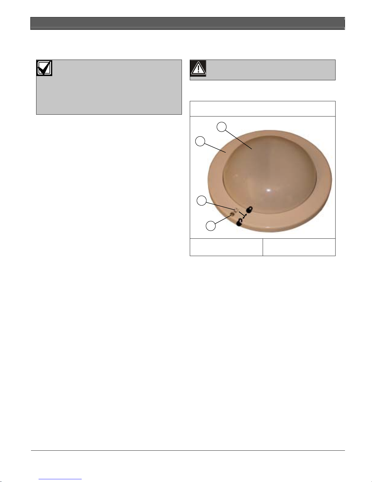
1. Remove the tamper screw on the base. Refer to
Figure 1.
Figure 1: PIR Detector
2
1
4
3
1 – Detector base
2 – Detector body
2. Push the tamper switch toward the tamper screw to
unlock (Figure 1).
3. Hold the base and turn the detector body
counterclockwise to remove from the base
(Figure 1).
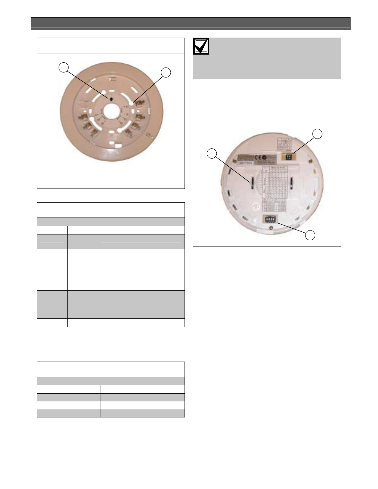
4. Position the base with the printed arrows pointing
in the direction of the desired coverage and mount
the base on the ceiling using the two mounting
screws. Refer to Figure 2 on page 3.
3 – Tamper screw
4 – Tamper switch
2 Bosch Security Systems | 8/05 | 4998154997B
ISN-CP1-CM-W50, ISN-CP1-CM-N100 | Installation Instructions | 2.0 Installation
.
Figure 2: PIR Detector Base
1
1 – Coverage direction
2 – Mounting holes
5. Wire the detector base (refer to Table 1).
When adding two or more detectors to a
wire run, the maximum length per gauge
decreases. Determine the new length by
dividing the length in Table 2 by the
2
number of detectors on the wire run.
6. Set the mirror adjustment switch (Figure 3) to the
appropriate position. Refer to the label on the back
of the detector.
Figure 3: PIR Detector Back
2
1
Table 1: Detector Terminals
Terminals Function Description
1, 2 Power
9 VDC to 28 VDC, no polarity
Input
3, 4 Alarm
Output
A selectable Form 1B normally
closed (NC) or Form 1A normally
open (NO) relay. This contact
opens when unpowered,
regardless of the DIP switch
settings (refer to Table 3).
5, 6 Tamper
Output
The Form 1B (NC) contacts open
when the body is detached from
the base, regardless of the power
supply conditions.
7 Spare No connection
Refer to Table 2 to determine the minimum gauge
wire required between the power source and the
detector. The table is based on one detector
connected to a 12 VDC power source.
Table 2: Wiring Specifications
Wire Gauge Maximum Length
0.3 mm2 (AWG 22) 700 m (2250 ft)
0.5 mm2 (AWG 20) 1200 m (3900 ft)
0.75 mm2 (AWG 18) 1800 m (5900 ft)
3
1 – Mirror adjustment switch
2 – DIP Switch 1
3 – DIP Switch 2
7. Set the DIP switches (Figure 3) to the appropriate
positions. Refer to Table 3 on page 4.
Bosch Security Systems | 8/05 | 4998154997B 3
 Loading...