


Bosch HBN34, HBN35, HBL35, HBN54, HBL56 Installation Manual
...
Installation Manual
Guide d’installation
Manual de instalación
Built-In Ovens
Models: HBL33, HBN33, HBL34, HBN34, HBL35, HBN35, HBL54, HBN54,
HBL56, HBN56, HBL57, HBL8550, HBL8650, HBL8750

Table of Contents
Safety . . . . . . . . . . . . . . . . . . . . . . . . . . . . . . . . . . . . . .1
Important Safety Instructions . . . . . . . . . . . . . . . . . . . . . . . . . . . . . . . . . . . . . . . 1
Preparation . . . . . . . . . . . . . . . . . . . . . . . . . . . . . . . . . .3
Before you Begin . . . . . . . . . . . . . . . . . . . . . . . . . . . . . . . . . . . . . . . . . . . . . . . . . 3
Tools and Parts Needed . . . . . . . . . . . . . . . . . . . . . . . . . . . . . . . . . . . . . . . . . . . . . . . . . . . . . . 3
Parts Included . . . . . . . . . . . . . . . . . . . . . . . . . . . . . . . . . . . . . . . . . . . . . . . . . . . . . . . . . . . . . . 3
27” Appliances . . . . . . . . . . . . . . . . . . . . . . . . . . . . . . . . . . . . . . . . . . . . . . . . . . 3
General Information . . . . . . . . . . . . . . . . . . . . . . . . . . . . . . . . . . . . . . . . . . . . . . . . . . . . . . . . . . 3
30” Appliances . . . . . . . . . . . . . . . . . . . . . . . . . . . . . . . . . . . . . . . . . . . . . . . . . . 7
Removing Packaging . . . . . . . . . . . . . . . . . . . . . . . . . . . . . . . . . . . . . . . . . . . . 11
For Convection Microwave Combination Units . . . . . . . . . . . . . . . . . . . . . . . . . . . . . . . . . . . . 11
Preparing Oven . . . . . . . . . . . . . . . . . . . . . . . . . . . . . . . . . . . . . . . . . . . . . . . . . . . . . . . . . . . . 11
Installation . . . . . . . . . . . . . . . . . . . . . . . . . . . . . . . . .12
Electrical Installation . . . . . . . . . . . . . . . . . . . . . . . . . . . . . . . . . . . . . . . . . . . . . 12
Oven Installation . . . . . . . . . . . . . . . . . . . . . . . . . . . . . . . . . . . . . . . . . . . . . . . . 14
Testing Operation . . . . . . . . . . . . . . . . . . . . . . . . . . . . . . . . . . . . . . . . . . . . . . . 15
Service . . . . . . . . . . . . . . . . . . . . . . . . . . . . . . . . . . . .16
Before Calling Service . . . . . . . . . . . . . . . . . . . . . . . . . . . . . . . . . . . . . . . . . . . . . . . . . . . . . . . 16
This Bosch Appliance is made by
BSH Home Appliances Corporation
5551 McFadden Ave.
Huntington Beach, CA 92649
Questions?
We look forward to hearing from you!
1-800-944-2904
www.boschappliances.com

Safety
Important Safety Instructions
m
READ AND SAVE THESE INSTRUCTIONS
WARNING:
If the information in this manual is not followed exactly, fire or shock may result
causing property damage or personal injury.
WARNING:
Do not repair or replace any part of the appliance unless specifically recommended
in the manuals. Improper installation, service or maintenance can cause injury or
property damage. Refer to this manual for guidance. All other servicing should be
done by a qualified technician.
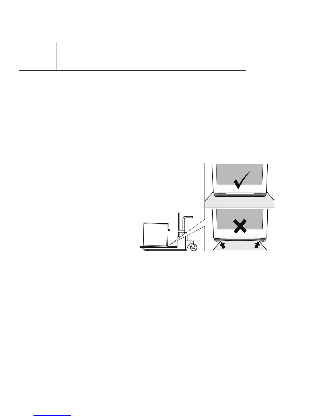
Appliance Handling Safety Do not lift appliance by door handle. Remove the door for easier handling and
installation. See instructions in Use and Care Manual.
Unit is heavy and requires at least two people or proper equipment to move.
Hidden surfaces may have sharp edges. Use caution when reaching behind or
under appliance.
Safety Codes and Standards This appliance complies with one or more of the following Standards:
• UL 858, The Standard for the Safety of Household Electric Ranges
• UL 923, The Standard for the Safety of Microwave Cooking Appliances
• UL 507, The Standard for the Safety of Electric Fans
• ANSI Z21.1, The American National Standard for Household Cooking Gas
Appliances
• CAN/CSA-C22.2 No. 113-M1984 Fans and Ventilators
• CAN/CSA-C22.2 No. 61-M89 Household Cooking Ranges
It is the responsibility of the owner and the installer to determine if additional
requirements and/or standards apply to specific installations.
Electric Safety Before you plug in an electrical cord, be sure all controls are in the OFF position.
If required by the National Electrical Code (or Canadian Electrical Code), this
appliance must be installed on a separate branch circuit.
Installer - show the owner the location of the circuit breaker or fuse. Mark it for easy
reference.
Important - Save these instructions for the local electrical inspector's use.
Before installing, turn power OFF at the service panel. Lock service panel to prevent
power from being turned ON accidentally.
Refer to data plate for more information. See "Data Plate" under "Service" for data
plate location.
English 1
Important Safety Instructions
m
READ AND SAVE THESE INSTRUCTIONS
Be sure your appliance is properly installed and grounded by a qualified technician.
Installation, electrical connections and grounding must comply with all applicable
codes.
Related Equipment Safety Remove all tape and packaging before using the appliance. Destroy the packaging
after unpacking the appliance. Never allow children to play with packaging material.
Never modify or alter the construction of the appliance. For example, do not remove
leveling legs, panels, wire covers or anti-tip brackets/screws.
Transport To avoid damage to the oven vent, use the transport method shown in the picture
below.
English 2
Preparation
Before you Begin
Tools and Parts Needed
Parts Included
• Phillips head screwdriver
• Measuring tape
• Drill with bit (1/8")
• Phillips head screws (6)
27” Appliances
General Information
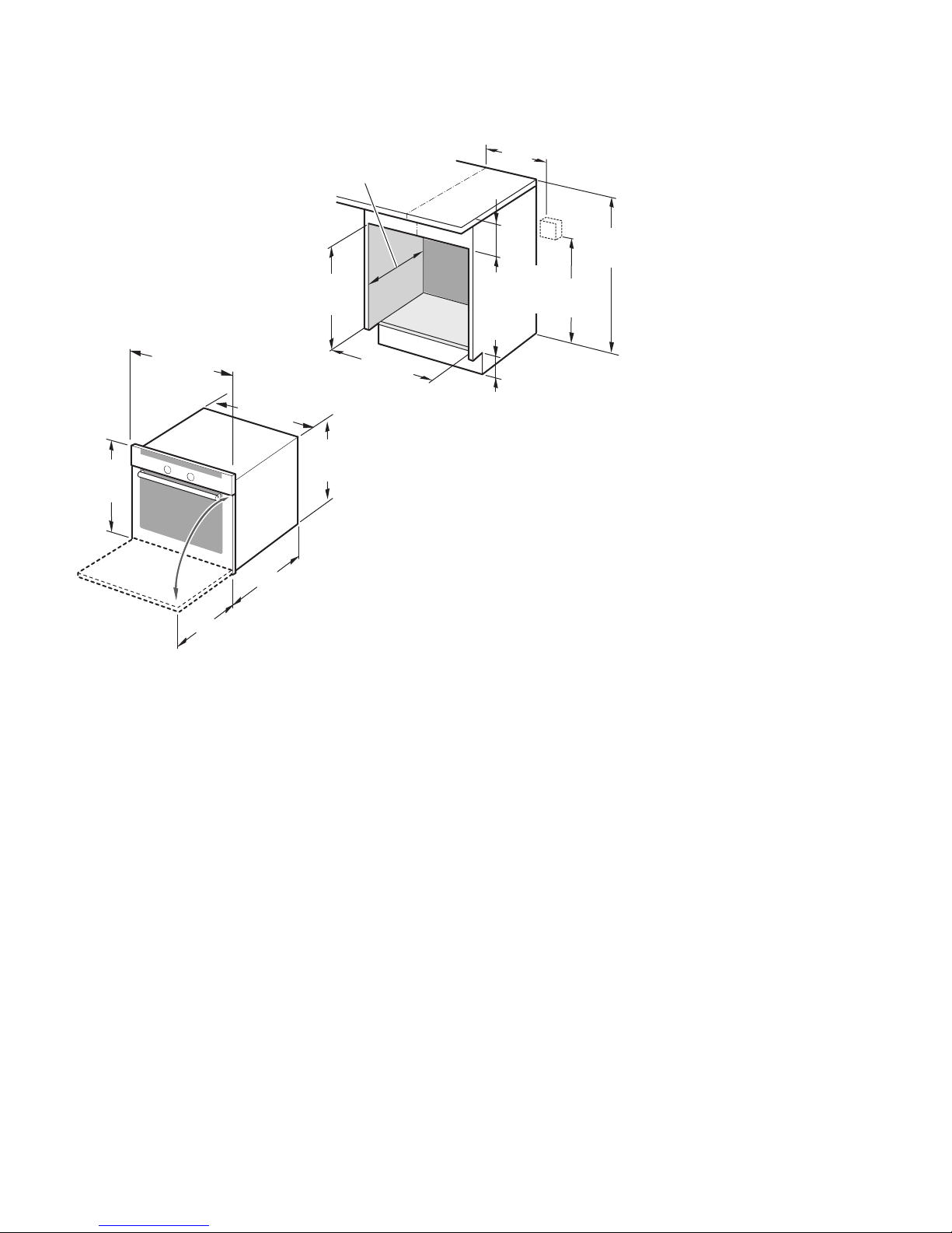
Power Requirements The outlet must be properly grounded in accordance with all applicable codes.
Dimensions for 27” Wall-Mounted Units
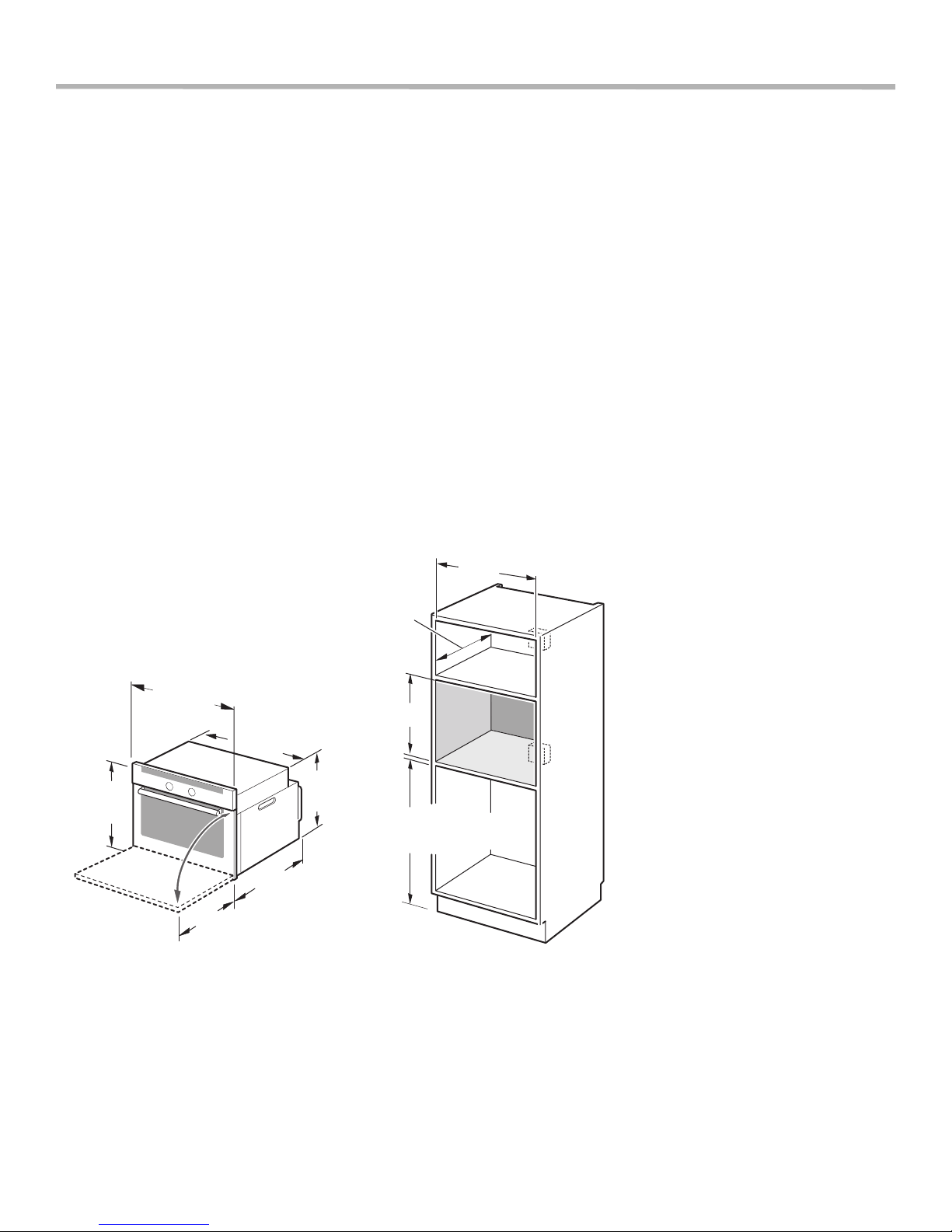
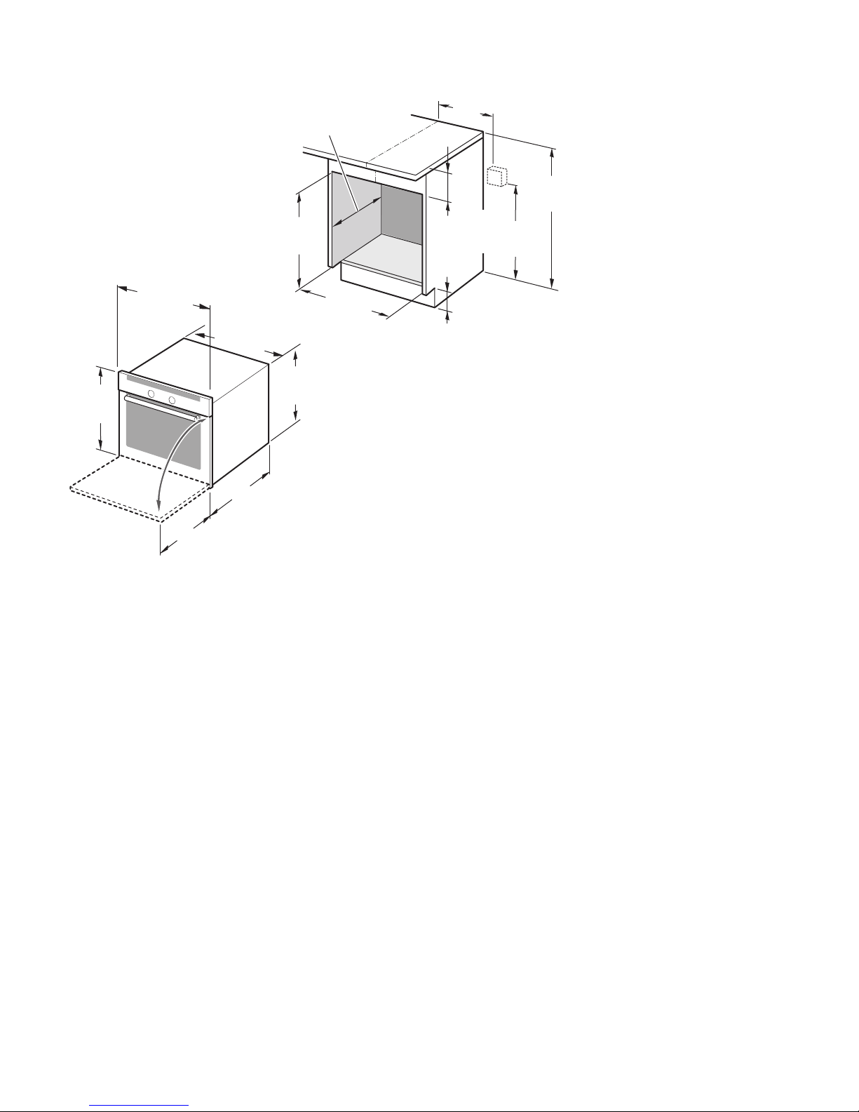
Single Oven 27”
It is good practice, when oven is
installed at the end of a cabinet run,
adjacent to a perpendicular wall or
cabinet door, to allow at least 1/4”
space between the side of the oven
and the wall/door.
For oven support, install 2x4’s
extending front to back flush with the
bottom and the side of the opening.
The supporting base must be well
secured to the floor/cabinet and level.
Note: The conduit box must be
installed either above or below the
unit. If the conduit box is installed
below the unit, a 2” diameter hole or
space is required between the back
wall and the right rear of the 2x4
supports.
The cabinet base must be flat and
capable of supporting a weight of at
least 210 lbs (95 kg).
1/16"
29
(738mm)
3/4"
26
(680mm)
22
13/16"
24
(630mm)
23
"
(559mm)
7/8"
(606mm)
(610mm)
(718mm)
"
27
(686mm)
"
24
1/4"
28
min. 4
max. 31
3/4"
(121mm)
3/8"
1/2"
25
(648mm)
(797mm)
English 3
3/4"
51
(1314mm)
3/4"
26
(680mm)
"
22
13/16"
24
(630mm)
7/8"
23
(559mm)
(610mm)
3/4"
49
(1264mm)
(606mm)
"
24
1/8"
51
(1299mm)
3/4"
9
(248mm)
1/2"
25
(648mm)
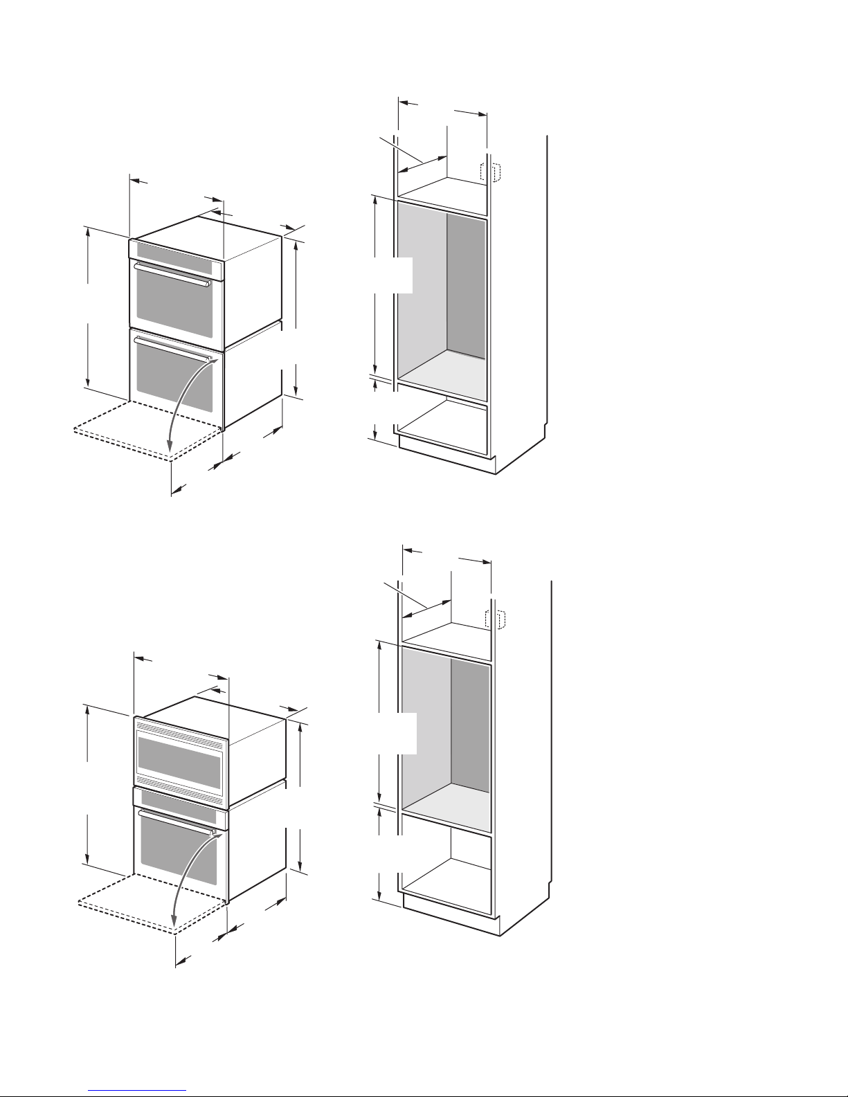
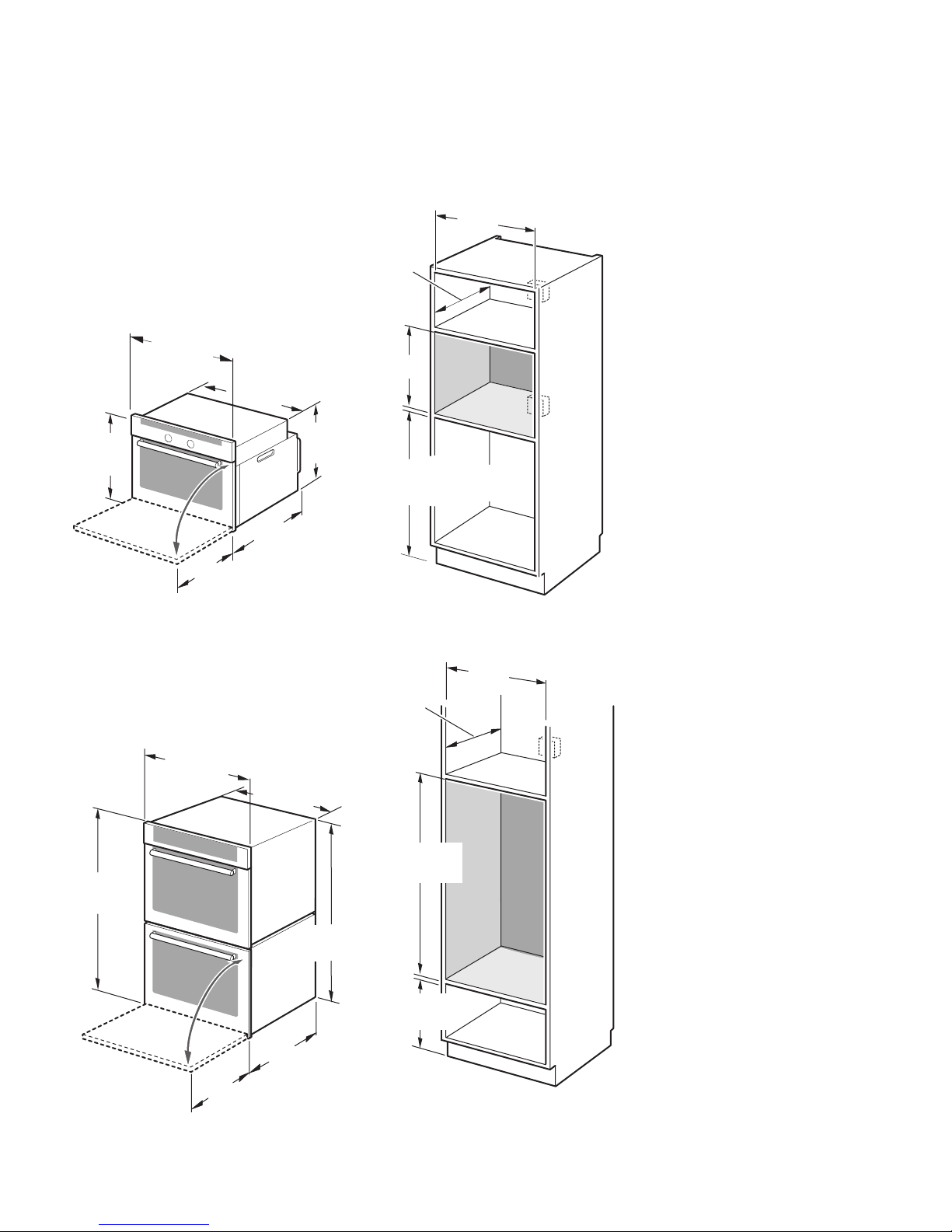
Double Oven 27”
It is good practice, when oven is
installed at the end of a cabinet run,
adjacent to a perpendicular wall or
cabinet door, to allow at least 1/4”
space between the side of the oven
and the wall/door.
For oven support, install 2x4’s
extending front to back flush with the
bottom and the side of the opening.
The supporting base must be well
secured to the floor/cabinet and level.
Note: The conduit box must be located
above the unit to facilitate connecting
and servicing.
The cabinet base must be flat and
capable of supporting a weight of at
least 355 lbs (161 kg).
"
50
(1270mm)
3/4"
26
(680mm)
13/16"
24
(630mm)
48
(1229mm)
7/8"
23
(606mm)
(610mm)
3/8"
"
24
1/2"
49
(1257mm)
1/2"
19
(500mm)
1/2"
25
(648mm)
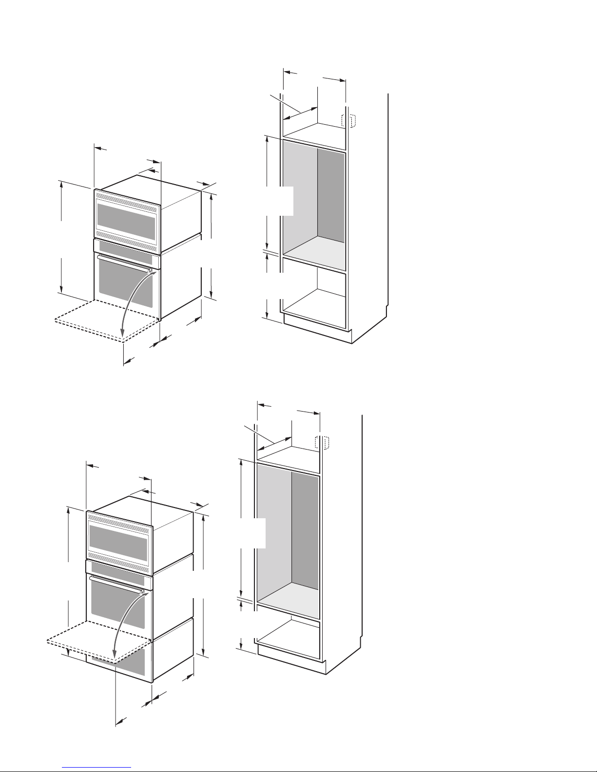
Combo Oven with Microwave 27”
It is good practice, when oven is
installed at the end of a cabinet run,
adjacent to a perpendicular wall or
cabinet door, to allow at least 1/4”
space between the side of the oven
and the wall/door.
For oven support, install 2x4’s
extending front to back flush with the
bottom and the side of the opening.
The supporting base must be well
secured to the floor/cabinet and level.
Note: The conduit box must be
located above the unit to facilitate
connecting and servicing.
The cabinet base must be flat and
capable of supporting a weight of at
least 330 lbs (150 kg).
"
22
(559mm)
English 4
3/8"
61
(1559mm)
3/4"
26
(680mm)
13/16"
24
(630mm)
59
(1514mm)
"
24
(610mm)
60
(1543mm)
5/8"
3/4"
9
(248mm)
3/4"
1/2"
25
(648mm)
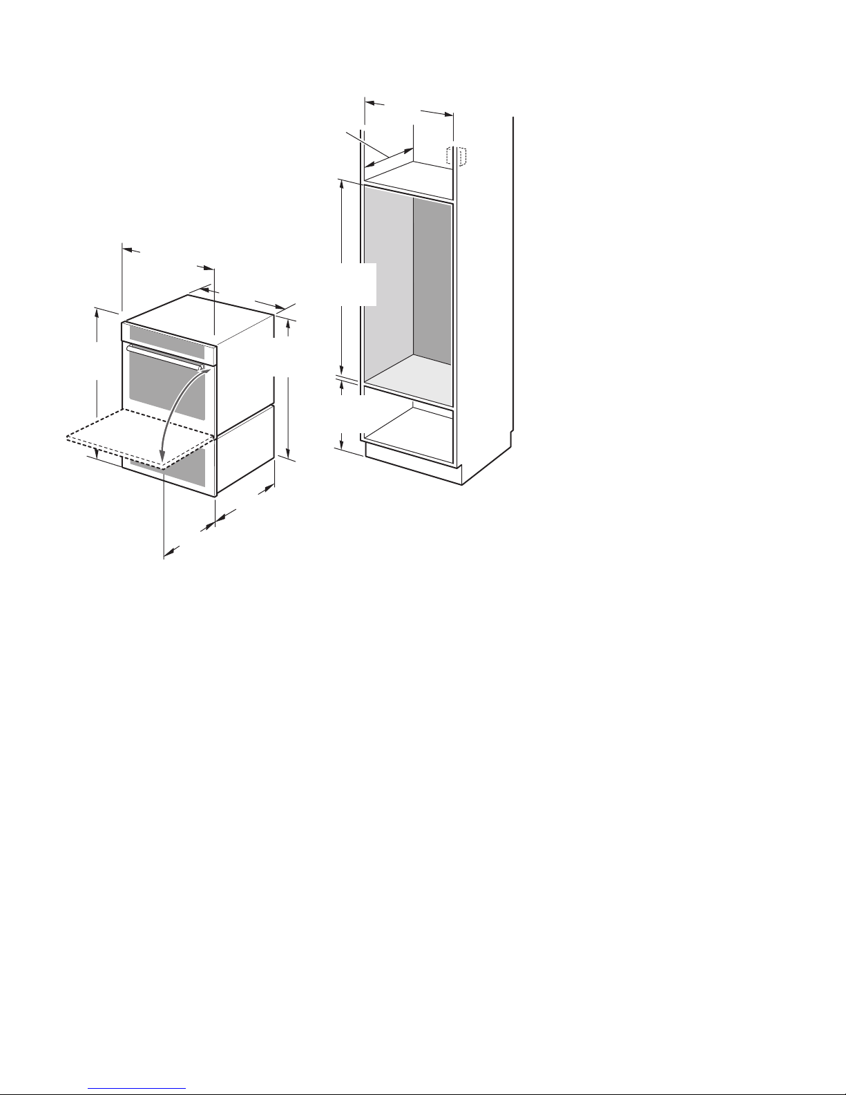
Combo Oven with Microwave and
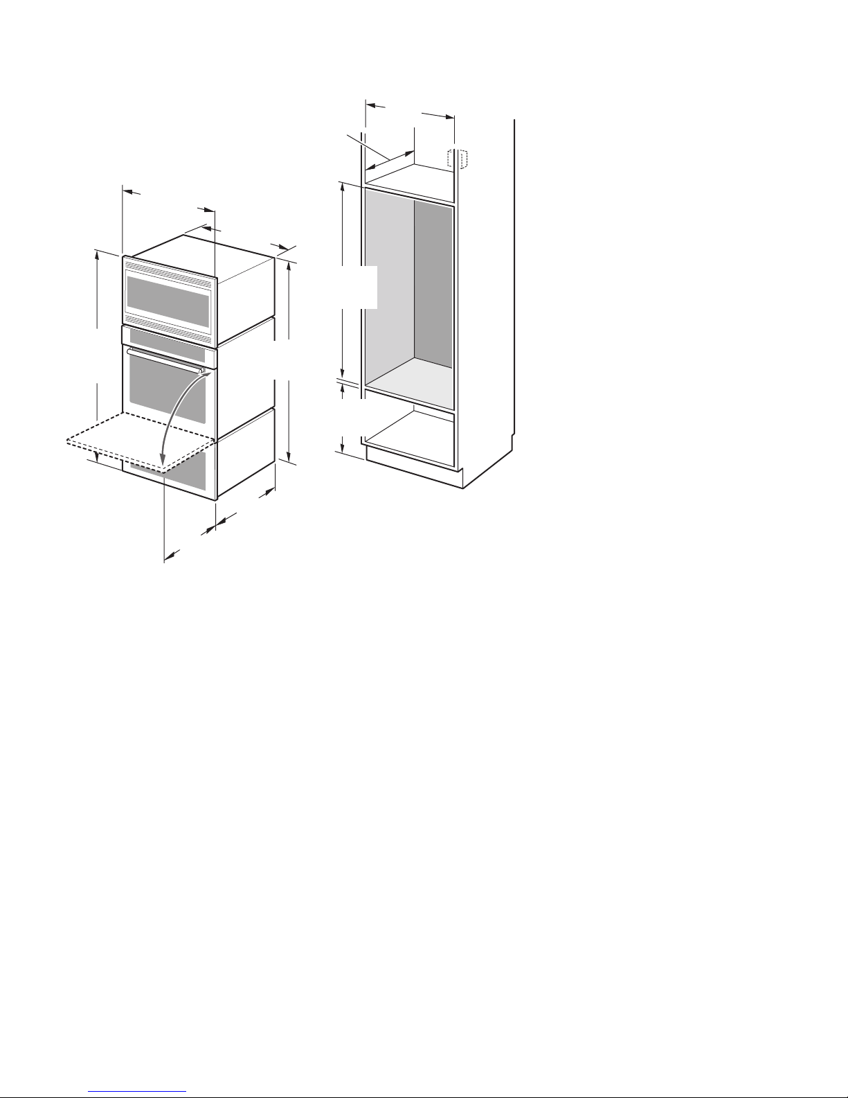
Warming Drawer 27”
It is good practice, when oven is
installed at the end of a cabinet run,
adjacent to a perpendicular wall or
cabinet door, to allow at least 1/4”
space between the side of the oven
and the wall/door.
For oven support, install 2x4’s
extending front to back flush with the
bottom and the side of the opening.
The supporting base must be well
secured to the floor/cabinet and level.
Note: The conduit box must be located
above the unit to facilitate connecting
and servicing.
The cabinet base must be flat and
capable of supporting a weight of at
least 370 lbs (168 kg).
"
(559mm)
22
23
7/8"
(606mm)
English 5
27” Under-the-counter units
3/4"
26
(680mm)
1/16"
29
(738mm)
(718mm)
13/16"
24
(630mm)
24
(610mm)
1/4"
28
(648mm)
"
27
(686mm)
25
1/2"
16
"
(419mm)
36
"
(915mm)
3/4"
1/2"
min. 3
(95mm)
"
4
"
20
(508mm)
(102mm)
"
22
(559mm)
23
7/8"
(606mm)
English 6
30” Appliances
Dimensions for 30” Wall-Mounted Units
1/16"
29
(738mm)
3/4"
29
(755mm)
22
13/16"
27
(706mm)
23
"
(559mm)
7/8"
(606mm)
(610mm)
(718mm)
"
27
(686mm)
"
24
1/4"
28
min. 4
max. 31
3/4"
(121mm)
3/8"
1/2"
28
(724mm)
(797mm)
Single Oven 30”
It is good practice, when oven is
installed at the end of a cabinet run,
adjacent to a perpendicular wall or
cabinet door, to allow at least 1/4”
space between the side of the oven
and the wall/door.
For oven support, install 2x4’s
extending front to back flush with the
bottom and the side of the opening.
The supporting base must be well
secured to the floor/cabinet and level.
Note: The conduit box must be
installed either above or below the
unit. If the conduit box is installed
below the unit, a 2” diameter hole or
space is required between the back
wall and the right rear of the 2x4
supports.
The cabinet base must be flat and
capable of supporting a weight of at
least 190 lbs (86 kg).
3/4"
51
(1314mm)
3/4"
29
(755mm)
22
27
(706mm)
23
"
(559mm)
13/16"
3/4"
49
(1264mm)
7/8"
(606mm)
"
24
(610mm)
51
(1299mm)
3/4"
9
(248mm)
1/8"
1/2"
28
(724mm)
Double Oven 30”
It is good practice, when oven is
installed at the end of a cabinet run,
adjacent to a perpendicular wall or
cabinet door, to allow at least 1/4”
space between the side of the oven
and the wall/door.
For oven support, install 2x4’s
extending front to back flush with the
bottom and the side of the opening.
The supporting base must be well
secured to the floor/cabinet and level.
Note: The conduit box must be located
above the unit to facilitate connecting
and servicing.
The cabinet base must be flat and
capable of supporting a weight of at
least 330 lbs (150 kg).
English 7
"
50
(1270mm)
3/4"
29
(755mm)
13/16"
27
(706mm)
48
(1229mm)
7/8"
23
(606mm)
(610mm)
3/8"
"
24
1/2"
49
(1257mm)
1/2"
19
(500mm)
1/2"
28
(724mm)
Combo Oven with Microwave 30”
It is good practice, when oven is
installed at the end of a cabinet run,
adjacent to a perpendicular wall or
cabinet door, to allow at least 1/4”
space between the side of the oven
and the wall/door.
For oven support, install 2x4’s
extending front to back flush with the
bottom and the side of the opening.
The supporting base must be well
secured to the floor/cabinet and level.
Note: The conduit box must be located
above the unit to facilitate connecting
and servicing.
The cabinet base must be flat and
capable of supporting a weight of at
least 290 lbs (132 kg).
3/8"
61
(1559mm)
22
3/4"
29
(755mm)
"
(559mm)
27
(706mm)
(1514mm)
13/16"
59
"
24
(610mm)
60
(1543mm)
5/8"
9
(248mm)
3/4"
3/4"
1/2"
28
(724mm)
Combo Oven with Microwave and
Warming Drawer 30”
It is good practice, when oven is
installed at the end of a cabinet run,
adjacent to a perpendicular wall or
cabinet door, to allow at least 1/4”
space between the side of the oven
and the wall/door.
For oven support, install 2x4’s
extending front to back flush with the
bottom and the side of the opening.
The supporting base must be well
secured to the floor/cabinet and level.
Note: The conduit box must be located
above the unit to facilitate connecting
and servicing.
The cabinet base must be flat and
capable of supporting a weight of at
least 310 lbs (141 kg).
7/8"
23
(606mm)
"
(559mm)
22
English 8
7/16"
40
(1027mm)
3/4"
29
(755mm)
13/16"
27
(706mm)
38
(968mm)
"
24
(610mm)
(1016mm)
1/8"
9
(248mm)
40
3/4"
"
1/2"
28
(724mm)
Combo Oven with Warming
Drawer 30”
It is good practice, when oven is
installed at the end of a cabinet run,
adjacent to a perpendicular wall or
cabinet door, to allow at least 1/4”
space between the side of the oven
and the wall/door.
For oven support, install 2x4’s
extending front to back flush with the
bottom and the side of the opening.
The supporting base must be well
secured to the floor/cabinet and level.
Note: The conduit box must be located
above the unit to facilitate connecting
and servicing.
The cabinet base must be flat and
capable of supporting a weight of at
least 290 lbs (132 kg).
"
(559mm)
22
23
7/8"
(606mm)
English 9
30” Under-the-counter-Units
3/4"
29
(755mm)
27
(706mm)
1/16"
29
(738mm)
28
(718mm)
13/16"
(686mm)
24
(610mm)
1/4"
28
(724mm)
"
27
"
1/2"
16
(419mm)
3/4"
min. 3
(95mm)
"
4
(102mm)
1/2"
(915mm)
"
20
(508mm)
36
"
"
22
(559mm)
23
7/8"
(606mm)
English 10
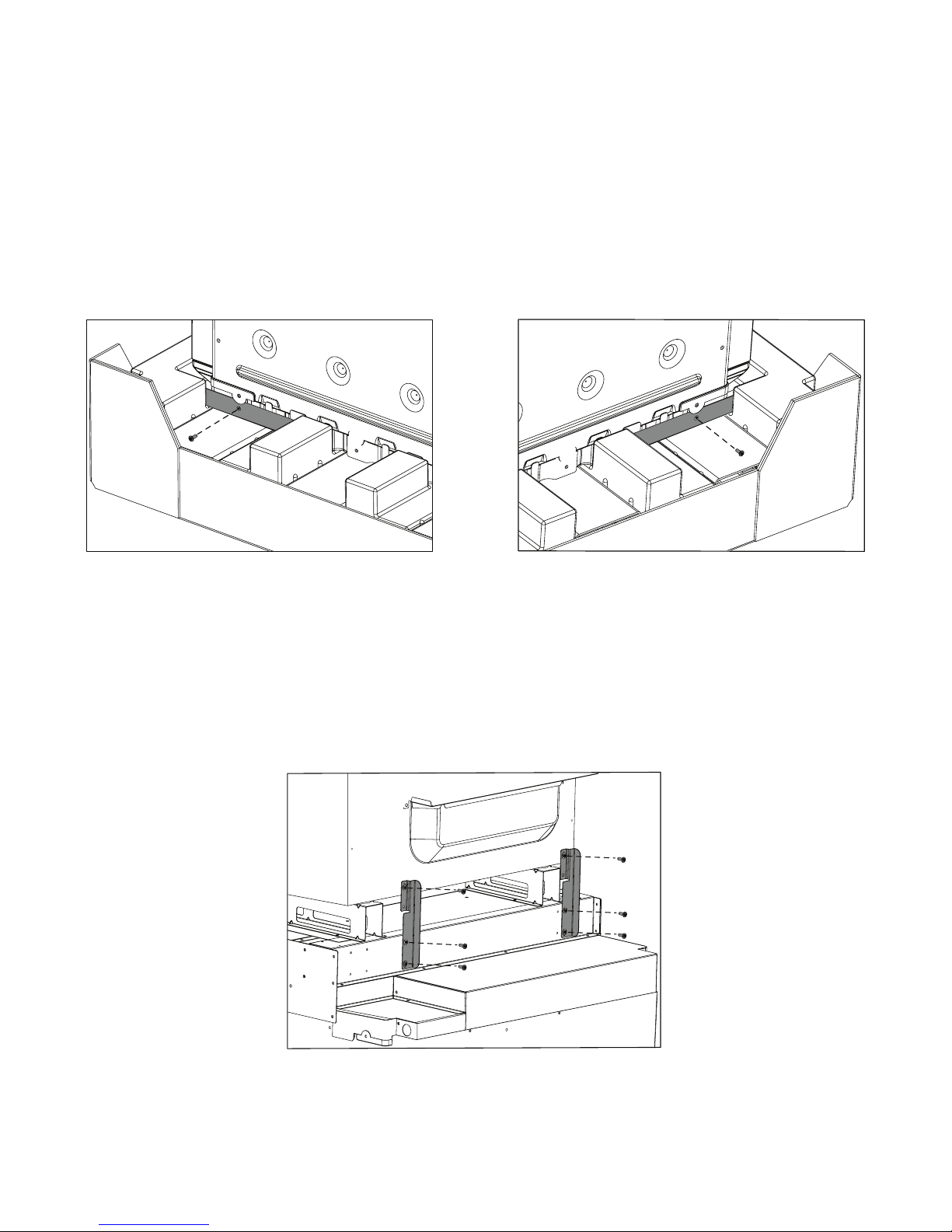
Removing Packaging
• Cut foil wrap in the area of corner posts.
• Remove foil completely.
• Remove top cardboard.
• Remove all top and side cardboard and Styrofoam braces.
• Place oven in front of cabinets where it is to be installed.
• Unscrew unit from Left and Right Brackets as show in “Left and Right
Packaging Bracket Removal.”
Left and Right Packaging Bracket Removal
Note: Bracket remains in packaging base. Unit should stay in packaging base plate until
ready to be lifted into cabinet cutout.
For Convection
Microwave Combination
Remove 2 rear support Convection Microwave Shipping Brackets prior to
installation as shown in “Convection Microwave Shipping Bracket Removal.”
Units
Convection Microwave Shipping Bracket Removal (for Convection Microwave Combination Units Only)
Preparing Oven
Place oven in front of cabinets where it is to be installed. Rest it on a jack or other
sturdy support so that it is in line with the cabinet cutout.
English 11
Installation
Electrical Installation
All model ovens on the front cover are dual rated, designed to be connected to
either 208/240V AC, 60 Hz, 4 wire, single-phase power supply.
HBN33, HBL33 25 AMP 30 AMP
Model Circuit Required
208V, 60 Hz 240V, 60 Hz
HBN34, HBL34,
HBN54, HBL54
HBL85
HBN35, HBL35,
HBN56, HBL56, HBL57,
HBL8650, HBL8750
The electrical supply should be a 4-wire single-phase AC. Install a suitable conduit
box (not furnished).
Important: Local Codes may vary, installation, electrical connections and
grounding must comply with all applicable local codes.
If local codes permit grounding through the electrical supply neutral, connect both
the white neutral wire and the bare ground wire from the oven to the white neutral
electrical supply wire.
30 AMP 30 AMP
40 or 50 Amp circuit. Refer to local electrical codes
for de-rating requirements.
English 12
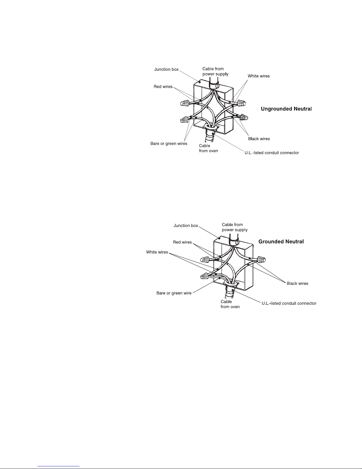
Electrical Connection The four-wire connection is preferred, but where local codes permit, the three wire
connection is also acceptable.
Four-wire Connection
• Connect the red oven wire to the red electrical supply wire (hot wire).
• Connect the black oven wire to the black electrical supply wire (hot wire).
• Connect the white neutral oven wire to the white neutral (not bare ground)
electrical supply wire.
• Connect the bare ground oven wire to the bare ground electrical supply wire.
Three-wire Connection
• Connect red wire from oven to red wire injunction box.
• Connect black wire from oven to black wire in junction box.
• Connect both green ground wire and white wire from oven to white (or gray)
neutral wire in junction box.
The conduit cable, where connected at the oven, swivels. Rotate conduit cable
upward (or downward) and direct through hole prepared in cabinet to attach to JBox.
To maintain serviceability, the flex conduit must not be shortened and should be
routed to permit temporary removal of the oven.
English 13
Oven Installation
Note: Before installing the oven be sure to verify the cabinet dimensions and electrical
connections.
Removing the Oven Door For ease of installation, some oven doors may be removed to reduce the weight of
the oven by 30 lbs (14 kg) per door, before installing into the cabinet. See “To
remove the oven door.”
CAUTION:
m
When removing the door:
• Make sure oven is cool and power to the oven has been turned
off before removing the door. Failure to do so could result in
electrical shock or burns.
• The oven door is heavy and fragile. Use both hands to remove
the oven door. The door front is glass. Handle carefully to avoid
breaking.
• Grasp only the sides of the oven door. Do not grasp the handle
as it may swing in your hand and cause damage or injury.
• Failure to grasp the oven door firmly and properly could result in
personal injury or product damage.
• To avoid injury from hinge bracket snapping closed, be sure that
both levers are securely in place before removing the door. Also,
do not force door open or closed - the hinge could be damaged
and injury could result.
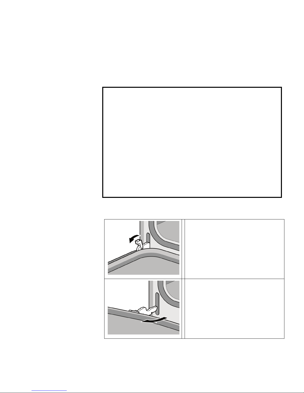
To remove the oven door:
1. Be sure to read the above CAUTION
before attempting to remove the door.
2. Open the door completely.
3. Flip levers on hinges toward you.
4. Close door carefully until it stops. It will
be about half way closed.
5. Holding the door firmly on both sides
using both hands, pull the door up and
out of the hinge slots. Hold firmly; the
door is heavy.
6. Place the door in a convenient and
stable location for cleaning.
English 14
Installing the Oven 1. Lift or slide unit into cabinet cutout. Do not lift appliance by door handle.
2. Push straight in until oven trim is flush with cabinet wall, being careful not to
crimp flexible conduit between oven and cabinet back wall. The oven should be
straight and level, not crooked.
3. Install supplied screws through tap holes in trim. (2 screws for single ovens, 4
screws for double/combo ovens)
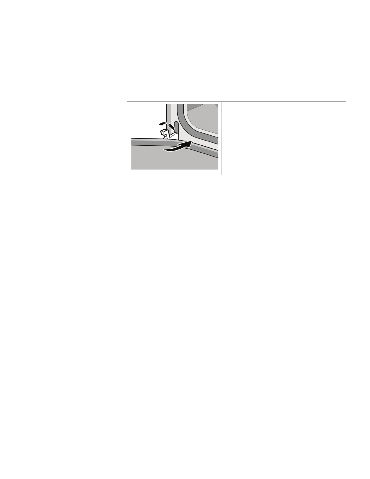
To replace the oven door:
1. Holding the door firmly in both hands,
place hinges in hinge slots.
2. Open door all the way to expose
hinges and slots.
3. Push lever down and away from you
until flush with the bracket.
4. Close and open door slowly to be sure
it is correctly and securely in place.
Door must be straight, not crooked.
Testing Operation
1. Turn on power at the breaker.
2. Check power at junction box using a volt meter.
For 240 V installation, the reading between the red and black wires (line to line)
should be 220 to 240 volts.
For 208 V installation, the reading between the red and black wires (line to line)
should be 190 to 208 volts.
3. Test the oven mode.
Select the BAKE mode. See the Use and Care Manual for detailed operation
instructions.
4. Verify that the oven light comes on and the oven begins to preheat.
5. Test the door lock.
Set the SELF CLEAN mode. Confirm that the door locks when the lock icon
appears in the display.
6. If installing a double oven, test the second oven as well.
7. If any of the tests do not result as explained above, contact Thermador service
for assistance. Otherwise, the installation is complete at this time.
English 15
 Loading...