


Bosch HBL87M53UC Installation Manual
Built-in and Combination Ovens
Installation Manual
HBL8463UC HBL8443UC HBL8743UC HBL8453UC
HBL8753UC HBL87M53UC

Table of Contents |
|
9 Safety Definitions ..................................................... |
3 |
IMPORTANT SAFETY INSTRUCTIONS ........................ |
4 |
Appliance Handling Safety ................................................. |
4 |
Safety Codes and Standards ............................................. |
4 |
Electric Safety ....................................................................... |
4 |
Related Equipment Safety .................................................. |
4 |
Proposition 65 Warning ...................................................... |
4 |
Transport ................................................................................ |
5 |
Bosch Combination Ovens ........................................... |
6 |
Before you Begin ........................................................... |
6 |
Tools and Parts Needed ..................................................... |
6 |
Parts Included ....................................................................... |
6 |
Power Requirements and Grounding ............................... |
6 |
For Best Installation ............................................................. |
6 |
Checklist ................................................................................ |
6 |
Removing Packaging .................................................... |
7 |
Built-in Ovens: ....................................................................... |
7 |
Combination Ovens: ............................................................ |
7 |
Packaging Bracket Removal-Left and Right Sides ........ |
7 |
Preparing Ovens ................................................................... |
7 |
Appliance and Cabinet Cutout Dimensions ............... |
8 |
Dimensions for Single Oven Units .................................... |
8 |
Dimensions for Combination Oven Units ........................ |
9 |
Electrical Installation - Grounding Instructions ....... |
11 |
Electrical Connection ....................................................... |
11 |
Four-wire Connection ....................................................... |
11 |
Three-wire Connection ..................................................... |
11 |
Oven Installation ......................................................... |
12 |
For Best Installation .......................................................... |
12 |
Pre-Assembly of the Combination Oven ...................... |
12 |
Remove Oven Door Prior to Installation ....................... |
14 |
Installing the Oven into the Cabinet .............................. |
15 |
How to Replace the Oven Door ..................................... |
16 |
Testing Operation .............................................................. |
17 |
Bosch® Support ........................................................... |
17 |
Before Calling Service ..................................................... |
17 |
Rating Label ....................................................................... |
17 |
Service ................................................................................ |
17 |
Parts and Accessories ..................................................... |
17 |
7KLV %RVFK $SSOLDQFH LV PDGH E\ %6+ +RPH $SSOLDQFHV &RUSRUDWLRQ
0DLQ 6WUHHW 6XLWH ,UYLQH &$
4XHVWLRQV"
ZZZ ERVFK KRPH FRP XV
:H ORRN IRUZDUG WR KHDULQJ IURP \RX
2

9Safety Definitions
9WARNING
This indicates that death or serious injuries may occur as a result of non-observance of this warning.
9CAUTION
This indicates that minor or moderate injuries may occur as a result of non-observance of this warning.
NOTICE: This indicates that damage to the appliance or property may occur as a result of non-compliance with this advisory.
Note: This alerts you to important information and/or tips.
3
9 IMPORTANT SAFETY INSTRUCTIONS
READ AND SAVE THESE INSTRUCTIONS
IMPORTANT: SAVE THESE INSTRUCTIONS FOR THE LOCAL ELECTRICAL INSPECTOR’S USE.
INSTALLER: LEAVE THESE INSTALLATION INSTRUCTIONS WITH THE UNIT FOR THE OWNER.
OWNER: PLEASE RETAIN THESE INSTRUCTIONS FOR FUTURE REFERENCE.
WARNING
If the information in this manual is not followed exactly, fire or shock may result causing property damage or personal injury.
WARNING
Do not repair, replace or remove any part of the appliance unless specifically recommended in the manuals. Improper installation, service or maintenance can cause injury or property damage. Refer to this manual for guidance. All other servicing should be done by an authorized servicer.
Appliance Handling Safety
CAUTION
Unit is heavy and requires at least two people or proper equipment to move.
For double and triple ovens three or more people are needed to assist with lifting the unit into place.
Do not lift appliance by door handle.
Hidden surfaces may have sharp edges. Use caution when reaching behind or under appliance.
Safety Codes and Standards
This appliance complies with the latest version of one or more of the following standards:
CAN/CSA C22.2 No. 61 - Household Cooking Ranges
UL 858 - Household Electric Ranges
CAN/CSA C22.2 No. 150 - Microwave Ovens
UL 923 - Microwave Cooking Appliances
CSA C22.2 No. 64 - Household Cooking and LiquidHeating Appliances
UL 1026 - Electric Household Cooking and Food Serving Appliances
It is the responsibility of the owner and the installer to determine if additional requirements and/or standards apply to specific installations.
Electric Safety
Before you plug in an electrical cord, be sure all controls are in the OFF position.
If required by the National Electrical Code (or Canadian Electrical Code), this appliance must be installed on a separate branch circuit.
Installer - show the owner the location of the circuit breaker or fuse. Mark it for easy reference.
Important - save these instructions for the local electrical inspector’s use.
Before installing, turn power OFF at the service panel. Lock service panel to prevent power from being turned ON accidentally.
Refer to rating label for more information. See “Rating Label” under “Service” for rating label location.
Be sure your appliance is properly installed and grounded by a qualified technician. Installation, electrical connections and grounding must comply with all applicable codes.
Related Equipment Safety
Remove all tape and packaging before using the appliance. Destroy the packaging after unpacking the appliance. Never allow children to play with packaging material
Never modify or alter the construction of the appliance. For example, do not remove leveling legs, panels, wire covers or anti-tip brackets/screws.
Before starting up the appliance, remove any packaging material and adhesive film from the cooking compartment and the door.
Proposition 65 Warning:
This product may contain a chemical known to the State of California, which can cause cancer or reproductive harm. Therefore, the packaging of your product may bear the following label as required by California:
67$7( 2) &$/,)251,$ 352326,7,21 :$51,1*
:$51,1*
&DQFHU DQG 5HSURGXFWLYH +DUP ZZZ3 :DUQLQJV FD JRY
4
9 IMPORTANT SAFETY INSTRUCTIONS
READ AND SAVE THESE INSTRUCTIONS
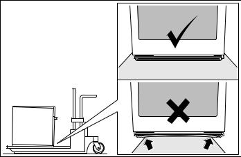
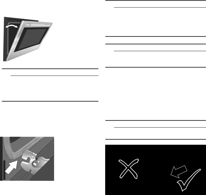
Transport
To avoid damage to the oven vent, use the transport method shown in the picture below.
5

Bosch Combination Ovens
The HBL8743UC, HBL8753UC and HBL87M53UC Bosch combination ovens are sold as sets, each of which includes two built-in oven components: a conventional wall oven (lower oven) and either a built-in speed oven or a microwave oven(upper oven).
For ease of installation and improved alignment, the oven components are assembled together in the customer’s home rather than at the factory.
Each of the components are packed in separate boxes, which are strapped together prior to shipping.
The combination ovens listed here are approved for use in a single cutout, using single power connection.
Each conventional oven component is designed with an oven-mounted junction box on top, which is used for connecting the upper oven power cable.
The hardware required for mounting the speed oven on top of the conventional oven will be found inside the conventional oven box.
Each of the oven components has its own rating label, the component model number, FD number, etc.
Before you Begin
Tools and Parts Needed
Phillips-head screwdriver
Star-head screwdriver (T20)
Measuring tape
Drill with bit (1/8”)
Gloves
Utility Knife
Parts Included
Phillips head screws (6).
Power Requirements and Grounding
The outlet must be properly grounded in accordance with all applicable codes.
For Best Installation
The oven can be difficult for two people to handle during installation. It is recommended that three or more people be available to assist with lifting the unit into place.
Removal of the oven door (to reduce the unit weight and to provide necessary gripping points) can be cumbersome unless the detailed door removal instructions are followed carefully. Do not attempt to remove the speed oven door.
Please take time to read and follow the instructions provided for an improved installation experience.
Checklist
Use this checklist to verify that you have completed each step of the installation process. This can help you avoid mistakes.
Before installing the oven, be sure to verify the cabinet dimensions are correct and the required electrical connections are present.
Refer to additional information in this manual regarding Safety, Cabinet Dimensions, Removing Packaging, Electrical Installation, Testing the Installation and Customer Service.
Remove the lower oven door to reduce the unit weight and to provide access to gripping points for lifting. See “Remove Lower Oven Door Prior to Installation” information.
Move the oven units into place in front of the cabinet opening, leaving the bottom packaging on the units to avoid damaging flooring.
Remove the Star-head screws (T-20 size using Starhead screwdriver) holding the speed microwave oven to the base of its carton.
Assemble the two units of the combination oven. See “Pre-Assembly of the Combination Oven”.
Connect the power cable from the lower oven to the junction box in the cabinet.
Remove the Star-head screws (T-20 size using Starhead screwdriver) holding the lower oven to the base of its carton.
Team-lift the unit directly into the cabinet cutout taking care not to pinch fingers, scratch arms or hands.
Slide the unit all the way into place.
Fasten the unit to the cabinet opening with the screws supplied using a Philips screwdriver.
Reinstall the oven door removed in Step 3 above.
Consult the complete installation instructions and follow the remainder of the procedures listed, including performing operation test.
INSTALLERLeave the literature pack and the accessories with the customer.
6
Removing Packaging
Built-in Ovens:
1.Cut the straps.
2.Open top of carton and remove top wood frame.
3.Lift the carton up and over the appliance to remove, or carefully cut along the cut line on the back left side of the carton with a blade shorter than 3/4” and remove carton.
4.Carefully remove internal protective packaging taking care to secure any loose accessories and instruction manuals.
5.Remove bracket(s) securing appliance to base pad, if present.
6.The unit should stay on the packaging base until ready to be lifted into cabinet cutout.
7.Install the appliance according to the installation instructions.
Combination Ovens:
1.Cut the straps and remove angle board/strap protectors from top of carton.
2.Open top of carton.
3.Lift the carton up and over the appliance to remove, or carefully cut along the cut line on the back left side of the carton with a blade shorter than 3/4” and remove carton.
4.Carefully remove the microwave or steam oven carton from top of bottom carton and place on floor.
5.Follow instructions on interior cartons for removal of remaining packaging.
Packaging Bracket Removal-Left and
Right Sides
Note: Actual bracket varies in appearance. The bracket remains in the packaging base. The unit should stay on the packaging base until ready to be lifted into cabinet cutout or onto the lower oven.
Preparing Ovens
Place ovens in front of the cabinet where it is to be installed so that they are in line with the cabinet cutout.
Check to be sure all packing materials have been removed from the unit. Also remove the accessories, oven racks, literature pack and any shipping materials from inside the oven cavity. Check both ovens for a double oven or combination oven installation.
7
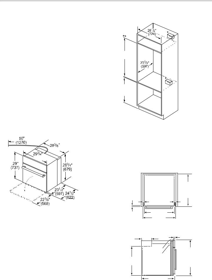
Appliance and Cabinet Cutout Dimensions
It is good practice, when an oven is installed at the end of a cabinet run, adjacent to a perpendicular wall, or cabinet door, to allow at least 1/4” (6.4 mm) space between the side of the oven and the wall/door.
For oven support, install 2x4s extending front to back flush with the bottom and the sides of the opening. The supporting base must be well secured to the floor/ cabinet and level.
Junction boxes can be located anywhere within reach of the oven’s power cable.
The cabinet base must be flat and capable of supporting the weight of the combination oven up to 429 lbs.
(195 kg).
Dimensions for Single Oven Units
The cabinet base must be flat and capable of supporting a weight of at least 232 lbs (105 kg).
Under oven dimensions are provided as a general guideline and may be adjusted as needed based on a particular application. Consult a design professional for optimizing personal preferences.
Single Oven Appliance Dimensions
PP
Single Oven Wall Mount Installation
ʌ¼ʚ
PLQ ë
PD[
PP
*For single ovens installed into a wall cabinet, the junction box may be located above, beneath, left or right of the unit within reach of the power cord.
**For oven installation in a wall cabinet, the control panel overlap is a minimum 3/8" (10mm) to max. 2" (51mm).
Single Oven Flush Mount Installation
Flush installation requires two side cleats to be attached inside the cabinet frame, recessed from the front.
Top View
|
|
ò |
|
|
|
|
|
ô |
ô |
IOXVK LQVHW |
|
UHYHDO |
UHYHDO |
GHSWK |
|
FOHDWV |
FOHDWV |
|
|
|
|
|
|
|
|
|
|
ò |
|
|
|
|
|
PP |
|
Side View
|
|
|
|
|
|
|
|
|
UHYHDO |
ǩ |
|
|
|
|
FOHDWV |
|
|
IOXVK |
|
|
ǫ |
|
|
FXW RXW |
|
|
|
|
|
KHLJKW |
|
|
|
|
|
ò |
|
PP |
8

Under-Counter Installation
 ê
ê

é
ê

* Includes ¾” (19 mm) base plate.
ë
PP
**For single ovens installed under a cabinet, the junction box should be located to the right or left of the unit within range of the power cord.
Dimensions for Combination Oven Units
The cabinet base must be flat and capable of supporting the weight of the combination oven up to 429 lbs
(195 kg).
Combination Oven Appliance Dimensions
 ë
ë
 ç¼ʚ
ç¼ʚ 

|
|
|
ʎ¼ʓʘ |
|
|
|
|
ʌ¼ʚ |
|
|
|
ê |
|
|
ê |
ç¼ʚ |
|
|
|
|
PP |
|
Combination Oven Traditional Installation
PLQ PD[
Note: Junction box may be installed above, below, to the left or to the right of the unit within reach of the power cord.
9
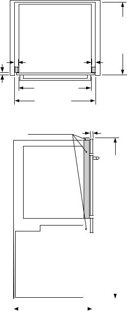
Combination Oven Flush Mount Installation
Flush installation requires two side cleats to be attached inside the cabinet frame, recessed from the front.
7RS 9LHZ |
|
|
|
|
|
ê |
|
ë |
ë |
IOXVK LQVHW |
|
GHSWK |
|||
UHYHDO |
UHYHDO |
||
|
|||
FOHDWV |
FOHDWV |
|
|
|
|
|
|
|
|
|
|
ê |
|
||
|
|
PP |
|
|
|
||
6LGH 9LHZ |
|
||
UHYHDO FOHDWV |
|||
|
|
||
|
|
è¼ʚ |
|
|
|
IOXVK FXWRXW |
|
|
|
KHLJKW |
|
|
|
|
|
|
|
|
|
|
|
|
|
|
|
|
|
|
|
|
|
|
|
|
|
|
|
|
|
|
|
|
|
|
|
|
|
|
|
|
|
|
|
|
|
|
|
|
|
|
|
|
|
|
|
|
|
|
|
|
|
|
|
ê |
|
|
|
|
|
|
PP |
||
|
|
|
|
||||||||
|
|
|
|
|
|
|
|||||
10
Electrical Installation - Grounding Instructions
The assembled combination oven should be moved in front of the cabinet opening and the power cable from the lower oven should be connected to the cabinet junction box.
All model ovens on the front cover of this installation instruction manual are dual rated, designed to be connected to either 208 or 240V AC, 60 Hz, 4 wire, single-phase power supply.
Model |
Circuit Required |
|
HBL8463UC |
208V, 60 Hz/ 240V, 60 Hz |
|
HBL8443UC |
||
30 AMP |
||
HBL8453UC |
||
|
||
|
|
|
HBL8743UC |
208V, 60 Hz/ 240V, 60 Hz |
|
HBL8753UC |
||
40 AMP |
||
HBL87M53UC |
||
|
||
|
|
The electrical supply should be a 4-wire single phase AC. Install a suitable conduit box (not furnished). An appropriately-sized, UL-listed conduit connector must be used to correctly attach the conduit to the junction box.
Note: Local codes may vary. Installation, electrical connections and grounding must comply with all applicable local codes.
If local codes permit grounding through the electrical supply neutral, connect both the white neutral wire and the green ground wire from the oven to the white neutral eletrical supply wire.
Electrical Connection
The four-wire connection is preferred, but where local codes permit, the three wire connection is also acceptable.
9WARNING
When connected to a 4 or 5-wire, 120/208-Volt 3- phase power supply, the phase C conductor is not required for the operation of the appliance.
Four-wire Connection
Ungrounded Neutral
SRZHU VXSSO\ |
|
|
MXQFWLRQ ER[ |
EODFN ZLUHV |
|
UHG ZLUHV |
||
|
||
JUHHQ RU EDUH |
|
|
ZLUH |
|
|
JUHHQ ZLUH |
ZKLWH ZLUHV |
|
8/ OLVWHG |
|
|
FRQQHFWRU |
FDEOH IURP |
|
|
RYHQ |
Connect the red oven wire to the red electrical supply wire (hot wire).
Connect the black oven wire to the black electrical supply wire (hot wire).
Connect the white neutral oven wire to the white neutral (not bare or green ground) electrical supply wire.
Connect the green ground oven wire to the bare or green ground electrical supply wire.
Three-wire Connection
Grounded Neutral
SRZHU VXSSO\ |
|
|
MXQFWLRQ ER[ |
EODFN ZLUHV |
|
UHG ZLUHV |
||
|
||
ZKLWH EDUH RU |
8/ OLVWHG |
|
JUHHQ ZLUH |
||
FRQQHFWRU |
||
|
||
ZKLWH ZLUH |
|
|
JUHHQ ZLUH |
FDEOH IURP |
|
|
RYHQ |
Connect red wire from oven to red wire in junction box.
Connect black wire from oven to black wire in junction box.
Connect both green ground wire and white wire from oven to white, green or bare neutral wire in junction box.
The conduit cable, where connected at the oven, swivels. Rotate conduit cable upward (or downward) and direct through hole prepared in cabinet to attach to junction box.
To maintain serviceability, the flex conduit must not be shortened and should be routed to permit temporary removal of the oven.
11
Oven Installation
NOTICE: Before installing the appliance, be sure to verify the cabinet dimensions and electrical connections.
For Best Installation
The oven can be difficult for two people to handle during installation. It is recommended to have three or more people available to assist with lifting the unit into place.
Removal of the oven door during installation (to provide the necessary handholds and to significantly reduce the unit weight) can be cumbersome unless the detailed door removal instructions are followed carefully. Please take time to read and follow the instructions provided for an improved installation experience.
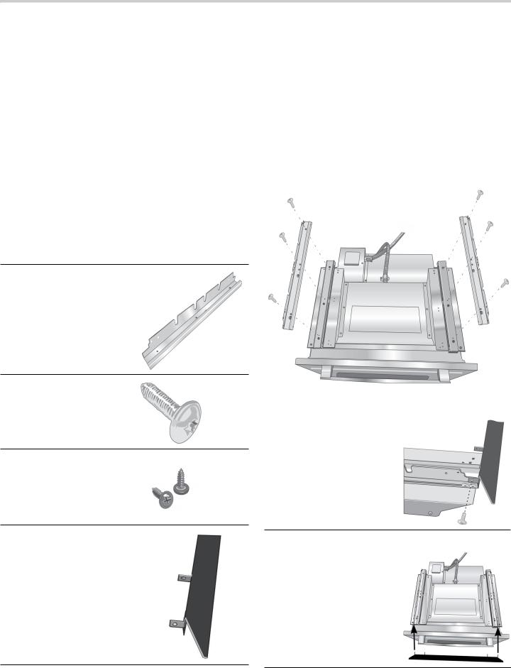
Pre-Assembly of the Combination Oven
Combination ovens require the oven and the microwave to be assembled prior to installing the combination unit into the wall cabinet.
Parts Provided
Universal connector bracket (2):
in parts box on top of oven
Screws (16):
in red bag inside parts box on top of oven.
Oven Mounting Screws (8): Screws are included to secure the oven trim to the cabinet. The screws are located in a small plastic bag affixed to the literature pack bag.
Trim Piece:
in plastic bag on top of oven.
Assembly of the two Oven Units
Notes
Do not place the oven into the wall cabinet until after mounting the speed oven on top of the lower oven and securing it with the universal connector brackets.
The universal connector brackets are interchangeable for the left and right sides of the oven. Be sure the taller vertical edge of the bracket is positioned to the outside of the oven.
1.Install both universal connector brackets on top of the lower oven using six (6) of the screws provided. Tighten screws securely, but do not overtighten.
2. Install decorative trim.
Position the decorative trim piece so the flanges with the holes in them face to the rear of the oven.
Align the outer flanges with the outside of the universal brackets. Fasten with one (1) screw each into the end hole of each universal bracket.
Tighten screws securely, but do not overtighten.
12
3.Place the speed oven on top of the universal connector brackets and fasten in place using three (3) screws per side. Tighten the screw securely, but do not overtighten.
Note: The existing screws in the speed oven base help with alignment. When lowering the speed oven into place on the universal connector brackets, allow these screw heads to slide into the slots as shown in the illustration below. The screw nearest the front of the speed oven should slide into the base of the slope at the front of the bracket.
4.Continue to “Connecting the Speed Oven Electrical Conduit to the Lower Oven”.
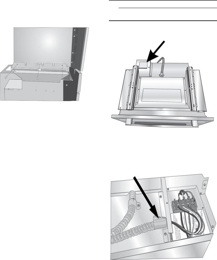
Connecting Speed Oven Electrical Conduit to Lower Oven
Note: When installing the combination unit, the power cable must be properly attached to the oven-mounted junction box. This must be done prior to supplying electrical power to the oven unit.
9WARNING
Check to be sure that no electrical power has yet been supplied to the oven.
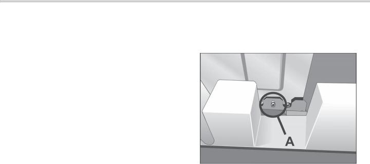
1.Remove the oven-mounted junction box cover located on the top rear of the oven. (See image below).
2.Remove the cap from the conduit access hole in the side of the oven-mounted junction box.
3.Guide the wires from the conduit cable coming from the speed oven through the hole in the oven-mounted junction box. There are four wires coming from the speed oven.
13
4.Snap the conduit connector into the hole by pressing it in until it clicks into place.
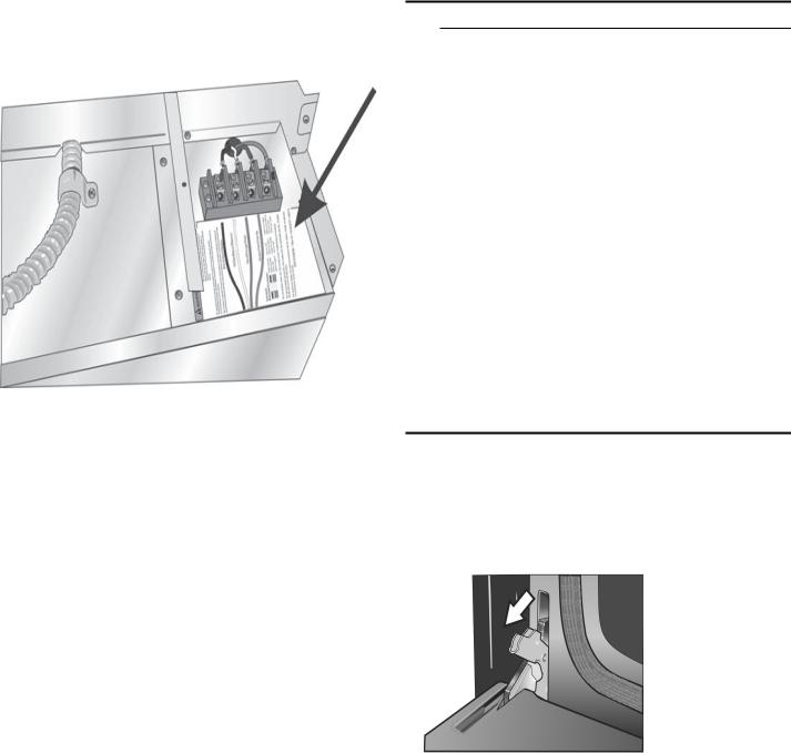
5.Follow the wiring diagram label and match and connect each wire by color to the wires attached to the wiring block inside the oven-mounted junction box. Push the bare end of the wire until it is snug in the wiring block then tighten down the retaining screw on each wire.
Tighten securely, but do not overtighten.
See previous illustration in Step 3 for finished appearance.
6.Replace the oven-mounted junction box cover and tighten the two screws holding it in place.
Tighten securely, but do not overtignten.
Remove Oven Door Prior to Installation
It is recommended to remove the conventional (lower) oven door to help reduce the unit weight.
NOTICE: Do not remove the speed oven door.
How to Remove the Oven Door
9WARNING
Make sure oven is cool and power to the oven has been turned off before removing the door. Failure to do so could result in electrical shock or burns.
The oven door is heavy and parts of it are fragile. Use both hands to remove the oven door. The door front is glass. Handle carefully to avoid breakage.
Grasp only the side of the oven door. Do not grasp the handle as it may swing in your hand and cause damage or injury.
Failure to grasp the oven door firmly and properly could result in personal injury or product damage.
To avoid injury from hinge bracket snapping closed, be sure both levers are securely in place before removing the door. Also, do not force door open or closed-the hinge could be damaged and injury could result.
Do not lay removed door on sharp or pointed objects as this could break the glass. Lay on a flat, smooth surface, positioned so that the door cannot fall over.
To help avoid injury or damage, be sure to read the above WARNING before attempting to remove the oven door.
1.Open the oven door to its fully open position.
2.Flip levers on hinges toward you.
Note: It may be necessary to use a tool, such as a screwdriver, to gently pry the upper part of the lever away from the housing. Take care to avoid scratching the housing.
3.Bring both door hinge levers to their fullest down position as shown in the illustration. The left and right door hinges differ slightly but operate in the same manner.
14
4.Close the oven door until it catches on the hinge stop levers, locking the hinges at the proper angle for door removal. The door will be open about 7 inches at the top. This takes the spring tension off the hinges so the door can be easily lifted out.
9CAUTION
PINCH HAZARD
Closing the door 7” takes the pressure off of the spring. If this isn’t done, the door can still be removed but the latch will now slam shut and will pinch or cut your hand.
5.The door is heavy. Use both hands to firmly grip it by the sides. Do not grip the door by the handle. Maintaining the door angle, lift the door straight up approximately 3/4” to unhook the hinges from the slots and then pull it out towards you until the hinges are clear of the oven housing.
6.Place the door in a convenient and stable location for cleaning.
Installing the Oven into the Cabinet
9CAUTION
It is recommended to wear gloves and long sleeves to protect hands and forearms from abrasion and potential scratches during the lifting process. It is also recommended to take off watches and jewelry and to wear work shoes during installation for foot protection.
9CAUTION
Three people or proper equipment are needed to safely lift the combination oven into the cabinet opening.
NOTICE: To avoid damage to the door, do not lift, pull or push the unit during installation by using any oven door handle as a gripping point.
Lifting Recommendations
There is a ridge across the top front of the oven cavity. Lift by grasping this ridge with one hand while placing the other hand on the back of the unit (for helpers lifting from the sides of the unit). If a third helper is lifting from the front, both hands should lift by holding this ridge area.
9CAUTION
DO NOT attempt to lift the unit by holding the oven’s upper heating element.
15
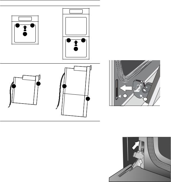
Proceed to lift the oven following the guidelines below with the door removed:
Lift points (1) on the front of the unit are for lifting from the sides of the unit. Lift point (3) on the front of the unit is for a third person to help lift the unit.
Lift point (2) on the back of the unit shows the location of the opposite hand for the helpers lifting from the sides of the unit. Adjust the location as needed to facilitate the lift.
Single Oven |
Combination Oven |
|
|
|
|
|
|
|
|
|
|
|
|
5.Install the supplied screws through the tap holes in the trim (2 screws for single ovens, 4 screws for combination ovens). It is recommended to drill pilot holes for the trim screws.
To ensure the door and oven function properly, the screws should be installed on the face of the side trim
6.Replace the oven door accordingly. See “Re-Install the Oven Door”.
How to Replace the Oven Door
1.Holding the door firmly in both hands, grip it on either side, not by the handle.
2.Tilt the door back slightly towards you until it opens about 7 inches at the top.
3.Slide the hinges into the slots as far as they will go and then lower the door straight down. The angle of the door may need to be adjusted slightly to allow the hinges to engage properly and the door to lower into place. The door should lower about 3/4” and stop. If not, the hinges have not engaged properly and the door could fall if it is released.

 #
#
"
Placing Oven Into Cabinet Opening
1.The unit and its bottom packaging (pallet) should be positioned close to and in front of the cabinet opening prior to beginning to lift the unit into place.
2.Lift or slide unit into the cabinet cutout without allowing the unit base to contact the flooring.
3.Guide the unit straight back into the cabinet cutout. Push the unit straight in until the oven trim is about 2 inches from being flush with cabinet wall.
Note: Be careful not to crimp the flexible conduit between the oven and the cabinet back wall. If necessary, guide the flexible conduit into the wall of cabinet access hole so it doesn’t prevent the unit from being pushed all the way into the cabinet opening. The oven should be straight and level.
4.Push the unit all the way back into the cabinet cutout until the front edge of the unit is flush with the front of the cabinet.
4.Once both hinges are fully engaged as described in Step 3, gently open the door until it is fully open.
5.Push the levers on both the hinges up and forward until they are locked into the slot and flush with the front of the oven body.
6.Close and open the door slowly to be sure it is correctly and securely in place.
16
 Loading...