

Page 1
FMM-7045, FMM-7045-D
Installation Instructions
EN
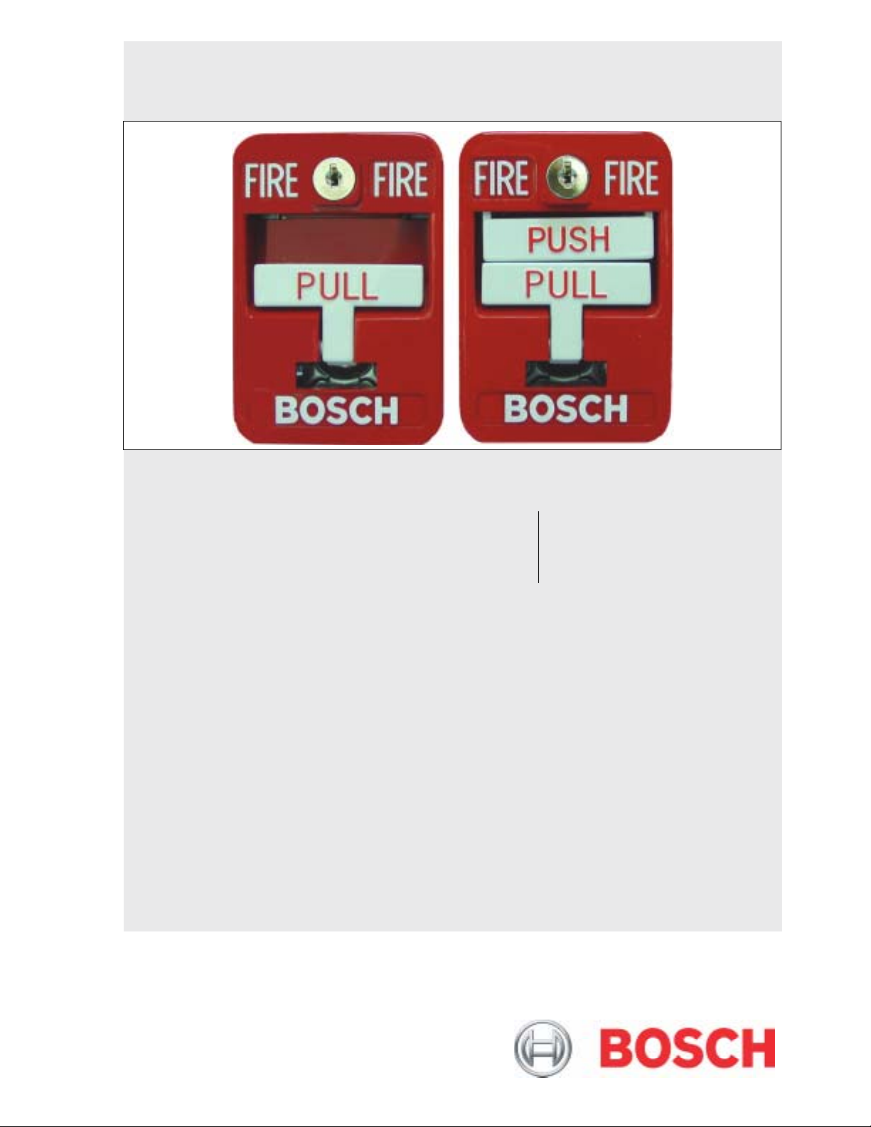
Multiplex Addressable
Manual Pull Stations
Page 2
FMM-7045, FMM-7045-D | Installation Instructions | 1.0 Description
Rotary switches are provided for convenient address
1.0 Description
These instructions cover the installation of Bosch
FMM-7045 (Single Action)/FMM-7045-D (Dual
Action) Multiplex (single-action) Multiplex Addressable
Pull Station in a fire system supervised by a Bosch
D7024 Series or DS9400 Series Fire Alarm Control
Panel (FACP) with firmware revision 2.0 or greater and
a D7039 or DS9431 Multiplex Expansion Module.
Install, test and maintain the FMM-7045/FMM-7045-D
according to these instructions, NFPA 72, Local Codes
and the Authority Having Jurisdiction (AHJ). Failure to
follow these instructions may result in failure of the
device to operate properly. Bosch is not responsible for
improperly installed, tested or maintained devices.
These instructions contain procedures to
follow in order to avoid personal injury and
damage to equipment.
NFPA 72 requires a complete system-wide
functional test be performed following any
modifications, repair, upgrades or
adjustments made to the system’s
components, hardware, wiring,
programming and software/firmware.
setting. These switches eliminate the need for an
external programmer.
The FMM-7045/FMM-7045-D is a single-action device
with a white pull-down lever in its center. The lever is
easily accessible to persons standing or in wheelchairs.
Pulling down on the lever breaks the glass rod. The
lever then latches in the down position and activates
the multiplex point, which then trips the fire alarm
control panel (FACP).
The lever cannot be reset until the proper key is
inserted in the lock. This feature allows emergency
personnel to determine the source of the alarm.
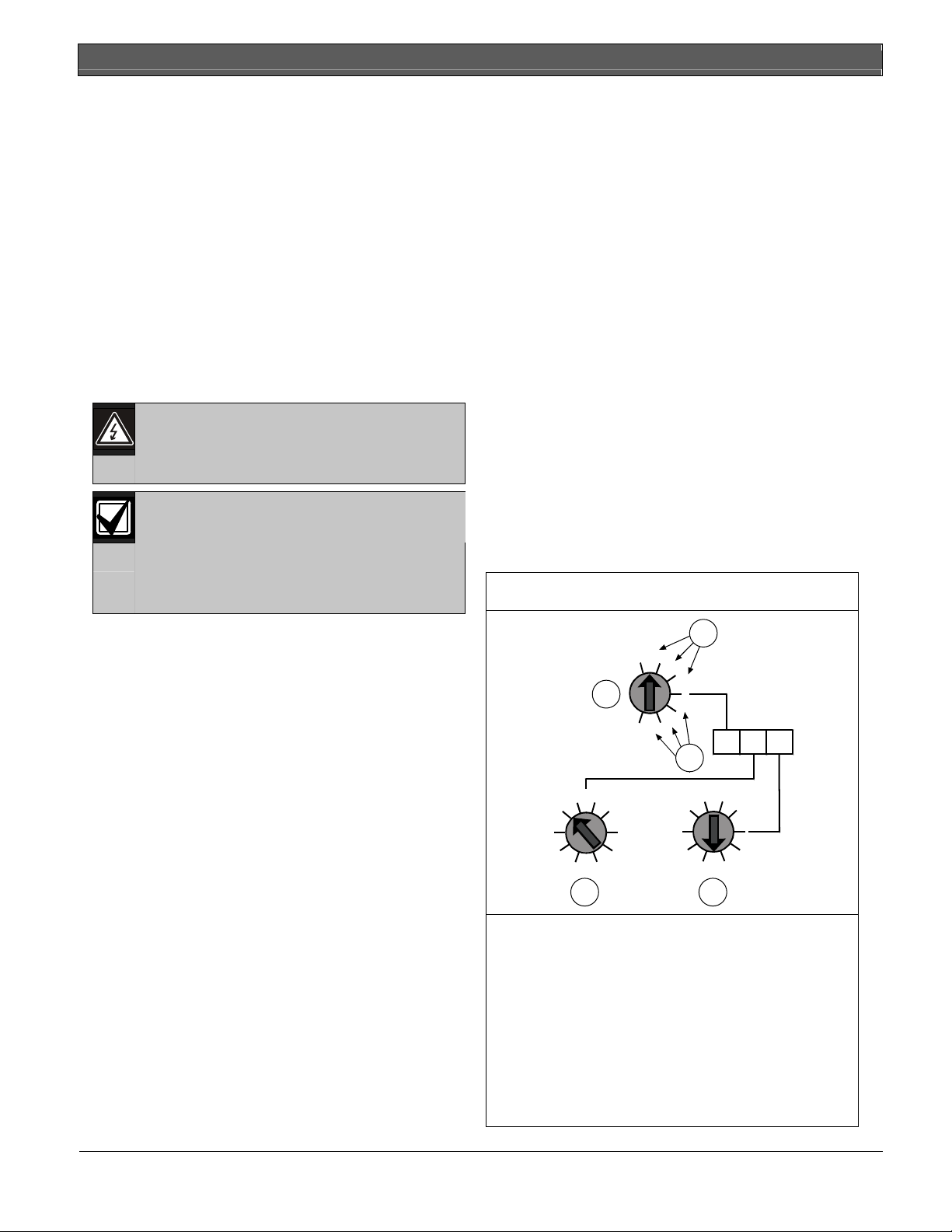
2.2 Setting the address
The FMM-7045/FMM-7045-D’s address is set by
positioning three rotary switches located on the front
side of the device. The switches click when turned. The
valid address range is 9 to 255. Check with the control
panel’s operation and installation manual for additional
address limitations.
Use a flat-bladed screwdriver to position each switch
when setting the FMM-7045/FMM-7045-D’s address.
See Figure 1 for details.
Figure 1: Setting the Address
The FMM-7045/FMM-7045-D Multiplex Addressable
Manual Pull Station is a UL Listed fire alarm initiating
device. It can be connected along with other Multiplex
devices on the D7039/DS9431 Multiplex Expansion
Module.
The D7024/DS9400 Series FACP supervises the entire
multiplex loop, including the FMM-7045/FMM-7045D, for troubles, alarms and ground fault conditions.
Since the FMM-7045/FMM-7045-D occupies only one
address on the multiplex bus, the module can be
addressed for any point within the 9 to 255 range
allowed by the D7039/DS9431 Multiplex Expansion
Module.
The FMM-7045/FMM-7045-D is generally installed
near building exits such as stairways and doors,
allowing persons evacuating the building to activate the
fire alarm. It is equipped with glass break rods and a
pull handle that locks in the activated position, to allow
easy identification of alarm activation point.
2.0 Installation
2.1 Operation
The FMM-7045/FMM-7045-D (single-action) Multiplex
Addressable Manual Pull Station is a UL Listed fire
alarm initiating device with a multiplex input module
connected to each pull station.
2
0
1
1
0
1
9
8
7
6
2
3
4
5
4 5
1 - Hundreds
2 - Use these addresses if using the D7024 Series
FACP with the D7039 Module.
3 - Use these addresses if using the DS9400
Series FACP with the DS9431 Module.
4 - Tens
5 - Ones
Example:
Hundreds Tens Ones = Address 095
0 9 5
2
0
1
2
X XX
3
0
1
9
8
7
6
2
3
4
5
2 Bosch Security Systems, Inc. | 8/06 | F01U001402C
Page 3

FMM-7045, FMM-7045-D | Installation Instructions | 3.0 Specifications
.
2.3 Wiring
Make sure all power is removed before
making any electrical connections. Failure
Run all wires and make all connections before
mounting the FMM-7045/FMM-7045-D. All wiring is
supervised and power limited. See Figure 2 for details.
Figure 2: Wiring the FMM-7045
1 - Previous device or D7039/DS9431
2 - Loop (+)
3 - Loop (-)
4 - Other devices
to do so may result in personal injury and/or
damage to equipment.
Do not loop wire around each terminal.
Break terminal wire connections for
supervision.
1
2
3
L
o
o
p
+
HUNDREDS
0
2
0
1
9
8
2
3467
5
TENS
2
3
L
o
o
p
-
1
2
0
1
X XX
0
1
9
8
2
7
3
4
6
5
ONES
4
2.4 Mounting
The FMM-7045/FMM-7045-D mounts to a 3 in. x 2 in.
x 3½ in. device box (like a Steel City CXW) or a 4 in.
x 2 1/8 in. square box with a 5/8 in. mud ring (like the
Steel City 52171 box and 52-C-14-5/8 mud ring) with
the two provided screws. The multiplex single zone
input module should easily fit inside.
The back plate mounting holes on the FMM7045/FMM-7045-D can be accessed by opening the
key lock on the unit.
The FMM-7045/FMM-7045-D Pull Stations
are for indoor use only. If a pull station is
needed for outdoor use or in an unheated
area, an FMM-100 Series Pull Station rated
for the environment should be wired to a
multiplex module within the interior of the
building.
3.0 Specifications
Table 1: Specifications
Panel
Programming
Type
Control Panel
Requirements
Multiplex Bus
Average Current
Draw
Optional
Equipment
Operating
Temperature
Listings and
Approvals
Nominal Bus
Voltage
Single Point
D7024 or DS9400 Series FACP (with
ROM version 2.0 or greater and a
D7039 or DS9431 Multiplex Expansion
Module installed). Refer to the D7024
Operation and Installation Guide (P/N:
31499) or the DS9400M/DS9400i
Installation Guide (P/N: 44578) for
specific programming information. Refer
to the D7039 Installation Instructions
(P/N: 38685) or the DS9431
Installation Instructions (P/N:
41831) for multiplex wiring information.
Alarm: 0.55 mA
Standby: 0.55 mA
Replacement Glass Break Rods (FMM100GR)
+32°F to +120°F (0°C to +49°C) noncondensing RH
UL864
CSFM
12 VDC
Bosch Security Systems, Inc. | 8/06 | F01U001402C 3
Page 4

Bosch Security Systems, Inc.
130 Perinton Parkway
Fairport, NY 14450-9199
Customer Service: (800) 289-0096
Technical Support: (888) 886-6189
© 2006 Bosch Security Systems, Inc.
F01U001402C
 Loading...