

Page 1
EA500
Installation Instructions
EN
Transponder
Page 2
EA500 | Installation Instructions |
8
6
7
2
5
1
4
3
1.0 Overview
EN | 2
1.0 Overview
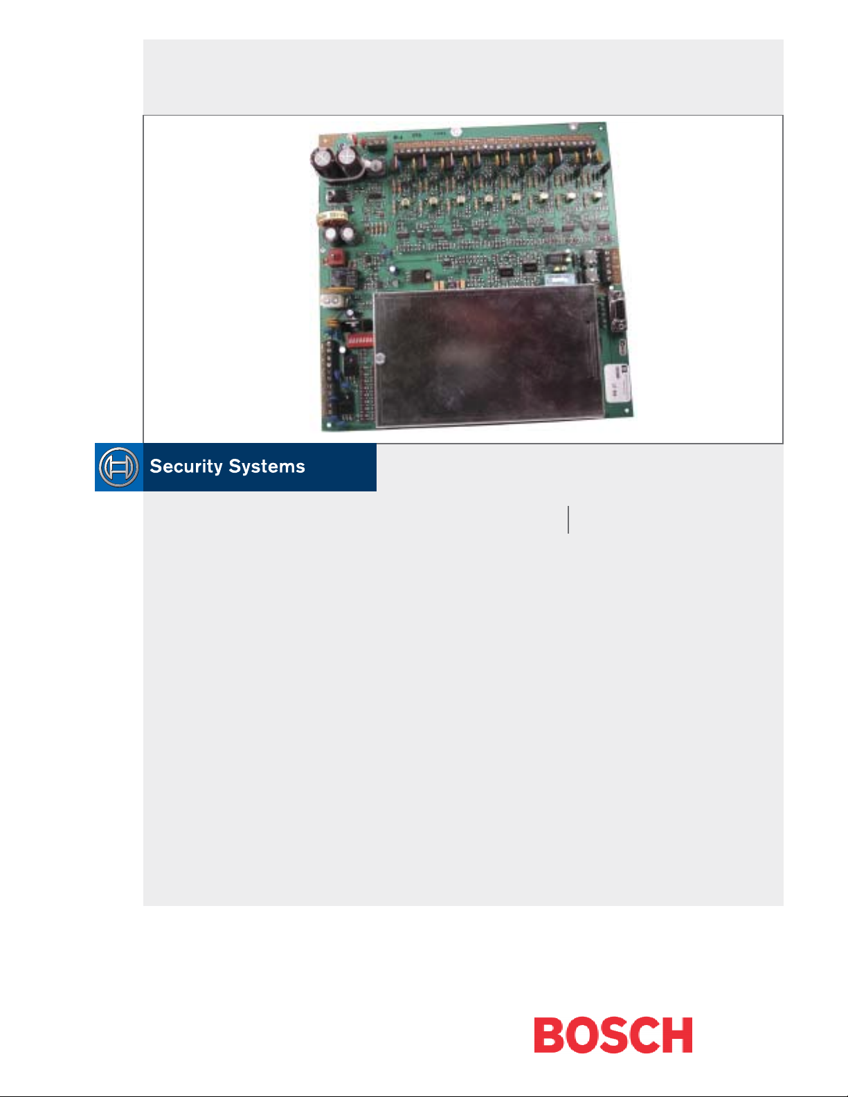
The EA500 Transponder is the Security Escort module
that provides communications between the central
console and the many receivers and alert units
throughout the protected area. In addition to its
communications functions, this transponder also
supplies power to the receivers. Each transponder also
includes drivers for a single strobe and siren.
2.0 Specifications
Table 1: Specifications
Enclosure (AE3)
(H x W x D)
Temperature
Range
Power
Power Output
Driver Outputs
Battery Backup
Multiplex Buses
Communications
Interface
Keyswitch Input
Compatibility
Tamper Switch
(option)
52.7 cm x 38.1 cm x 10.8 cm
(20.75 in. x 15 in. x 4.25 in.)
-40°C to +65°C (-40°F to +149°F)
18.0 VAC, 50 VA maximum plug-in
transformer for 110 V, 60 Hz
9 VDC used for SE485 or Proxim
radio power
Strobe: 500 mA solid state sink,
terminal switches to ground in an
alarm condition.
Siren: 500 mA solid state sink,
terminal switches to ground in an
alarm condition.
12 VDC lead acid battery
Eight multiplex drivers, each capable
of driving eight receivers or alert
units for a combined total of 64
receivers and alert units per
transponder.
Selectable SE485 or RS-232
47k EOL resistor, supervised loop
ROM version 4.00 or greater (the
version shipped with this unit) is
compatible with “–304” equipment
(such as EA102A-304). Version
4.00 or greater is
with non “–304” equipment.
ROM versions earlier than 4.00 are
compatible with non “-304”
equipment.
P/N: CTS1-70, Normally Closed
not
compatible
3.0 Mounting
Normally, the enclosures are mounted first and all
wiring is run. Then the electronics are mounted, wired,
and tested.
The enclosures include hardware for mounting the
enclosure to a wall and mounting the circuit board to
the enclosure.
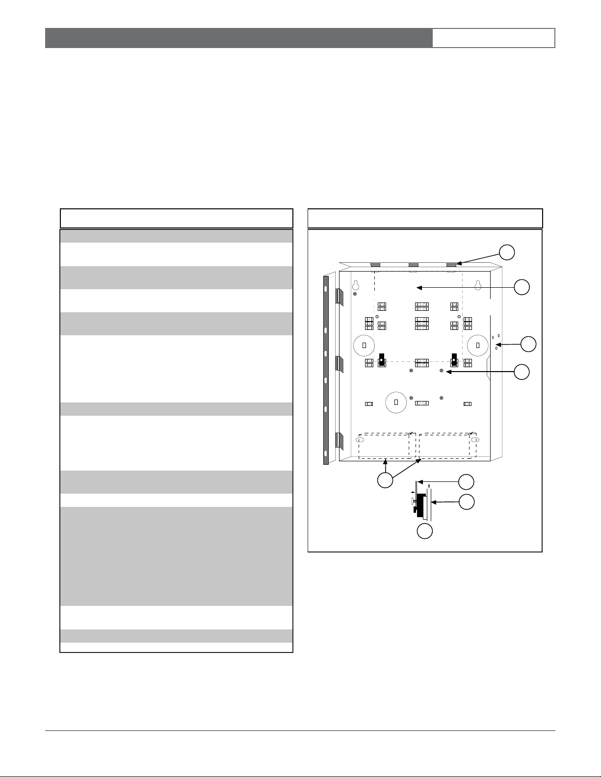
1. Mount the enclosure to the mounting surface.
2. Mount the circuit board to the enclosure. See Figure
1.
Figure 1: Enclosure
1 - View to show retainer tabs. Insert board between
tabs to secure.
2 - Circuit location
3 - Tamper switch mounting location
4 - Support post
5 - Battery location
6 - Enclosure
7 - Circuit board
8 - Support post assembly
Bosch Security Systems | 6/03 | 33829E
Page 3
EA500 | Installation Instructions |
1
2
3
4
BUS 0 PWR 0
_+_
+
BUS
POWER
_
+
_
+
BUS
POWER
_
+
_
+
-
TX
+
GND
-
RX
+
5
6
4
4.0 Wiring
EN | 3
4.0 Wiring
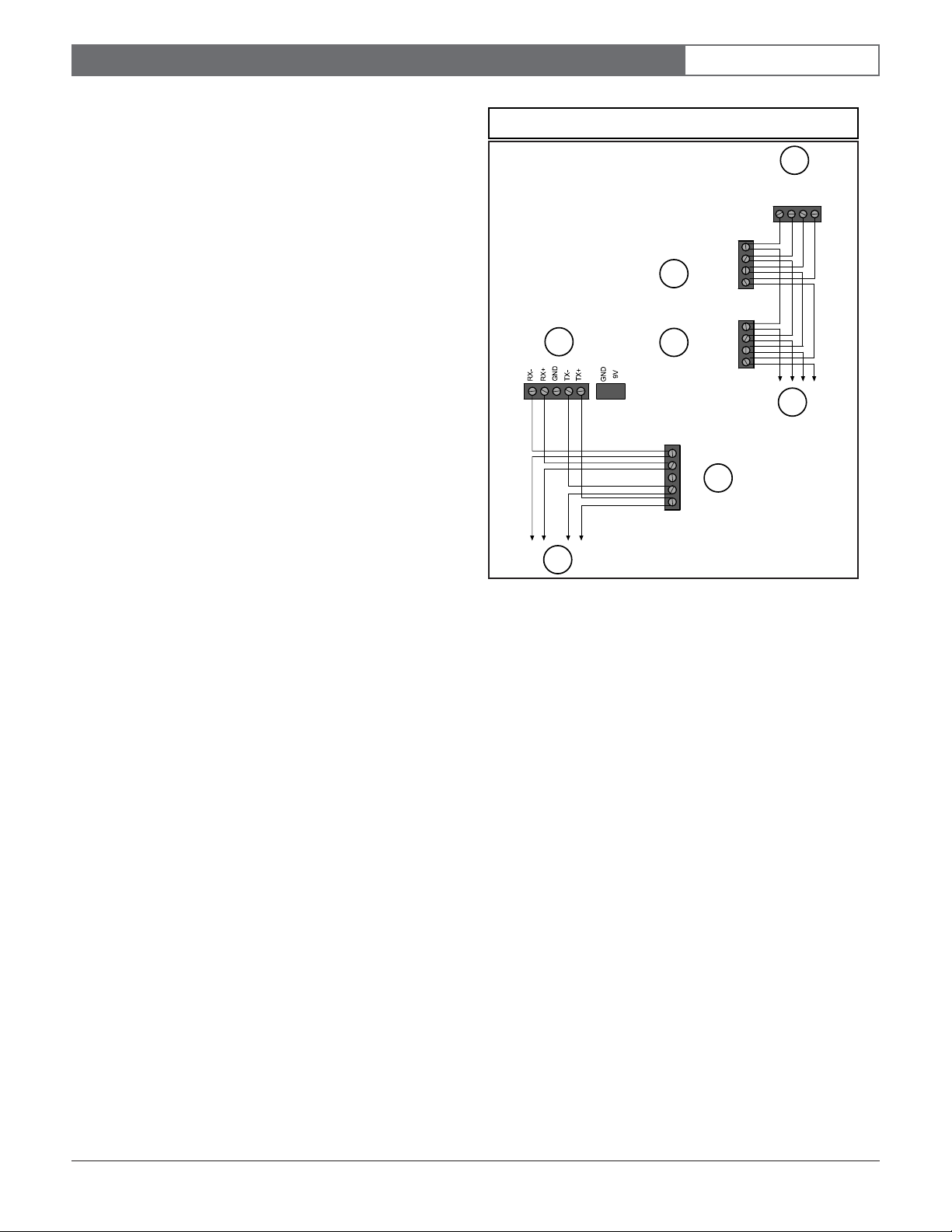
Wire the transponder according to Figure 2.
The wiring to the receivers and alert units can be as
home-run (individual), daisy-chain (device to device), or
a combination of both. T-tapping is also acceptable. The
recommended cable is 4-conductor, 18 AWG
(1.2 mm [0.05 in.]) fire rated.
Wiring from SE485 to the transponders can be home-run
(individual), daisy-chain (device to device), or a
combination of both. T-Tapping is also acceptable. The
recommended cable is 4-conductor, twisted pair,
non-shielded, 22 AWG (0.8 mm [0.03 in.]).
Figure 2: Wiring
1 - Transponder
2 - Typical receiver
3 - Typical output module
4 - To next device
5 - SE485
6 - To next transponder
Bosch Security Systems | 6/03 | 33829E
Page 4

EA500 | Installation Instructions |
5.0 Setting the Address
5.0 Setting the Address
Every transponder in the system must have its own
address. Set the address on the transponder using the
DIP switches located in the upper-right corner (see
Figure 3).
Figure 4 shows to set the DIP switches for each possible
address.
Figure 3: Transponder
EN | 4
14
13
1
2
3
-
TX
+
GND
-
RX
+
OFF
ON
12
11
10
9
Bus 0
Bus 1
Bus 2
Bus 3
Bus 4
Bus 5
Bus 6
4
Enable
Enable
Enable
Enable
Enable
Enable
Enable
Bus 7
Enable
8
7
5
_+_+_+_+_+_+_+_+_+_+_+_+_+_+_+_
BUS 0 PWR 0 BUS 1PWR 1BUS 2PWR 2 BUS 4PWR 4BUS 5PWR 5BUS 6PWR 6BUS 3 PWR 3 BUS 7 PWR 7
1 - RS-232 port
2 - Select RS-232/SE485
3 - SE485
4 - Bus enable (0 to 7)
5 - Bus power bar (0 to 7)
6 - Transformer
7 - AC power LED
8 - 18 VAC input power
9 - Power switch (Do not disconnect AC input power.)
10 - Battery
11 - 12 VDC battery connector
12 - Transponder address
13 - 9 V radio power; keyswitch; tamper; strobe (12 VDC, 0.5 A current sink);
alert siren (12 VDC, 0.5 A current sink)
14 - Bus 0 = Comm fail; Bus 1 = Carrier detect; Bus 2 = Transmit data; Bus 3 = Receive data;
Bus 4 = CRC error; Bus 5 = Test in progress; Bus 6 = Alarm in progress; Bus 7 = Heartbeat
AC AC EARTH
+
GROUND
6
Bosch Security Systems | 6/03 | 33829E
Page 5

EA500 | Installation Instructions |
Figure 4: DIP Switch Settings
5.0 Setting the Address
EN | 5
ON
O
n
OFF
1 2 3 4 5 6 7 8 1 2 3 4 5 6 7 8 1 2 3 4 5 6 7 8 1 2 3 4 5 6 7 8 1 2 3 4 5 6 7 8 1 2 3 4 5 6 7 8 1 2 3 4 5 6 7 8 1 2 3 4 5 6 7 8
1
2
3
4
5
6
7
8
9
10
11
12
13
14
15
16
17
18
19
20
21
22
23
24
25
26
27
28
29
30
31
32
33
34
35
36
37
38
39
40
41
42
43
44
45
46
47
48
49
50
51
52
53
54
55
56
57
58
59
60
61
62
63
64
65
66
67
68
69
70
71
72
73
74
75
76
77
78
79
80
81
82
83
84
85
86
87
88
89
90
91
92
93
94
95
100
101
102
103
104
105
106
107
108
109
110
111
112
113
114
115
116
117
118
119
120
121
122
123
124
125
126
127
96
97
98
99
128
129
130
131
132
133
134
135
136
137
138
139
140
141
142
143
144
145
146
147
148
149
150
151
152
153
154
155
156
157
158
159
160
161
162
163
164
165
166
167
168
169
170
171
172
173
174
175
176
177
178
179
180
181
182
183
184
185
186
187
188
189
190
191
192
193
194
195
196
197
198
199
200
201
202
203
204
205
206
207
208
209
210
211
212
213
214
215
216
217
218
219
220
221
222
223
224
225
226
227
228
229
230
231
232
233
234
235
236
237
238
239
240
241
242
243
244
245
246
247
248
249
250
251
252
253
254
255
Bosch Security Systems | 6/03 | 33829E
Page 6

EA500 | Installation Instructions |
Notes:
EN | 6
Notes:
Bosch Security Systems | 6/03 | 33829E
Page 7

EA500 | Installation Instructions |
Notes:
EN | 7
Notes:
Bosch Security Systems | 6/03 | 33829E
Page 8

Bosch Security Systems
130 Perinton Parkway
Fairport, NY 14450-9199 USA
www.boschsecurity.us
Customer Service: (800) 289-0096
Technical Support: (888) 886-6189
© 2003 Bosch Security Systems
Subject to change | Printed in the USA
33829E
 Loading...