

Bosch DLA-AIOU0-04AT User Manual
1200 Series IP Video Storage System
en Installation Manual

1200 Series IP Video Storage System Table of Contents | en 3
Table of Contents
1 Safety Instructions 4
1.1 Overview 4
1.2 Warnings and Precautions 4
1.3 Preparing for Setup 4
1.4 Electrical Safety Precautions 4
1.5 General Safety Precautions 5
1.6 System Safety 5
2System Overview 6
3 System Interface 7
3.1 Control Panel Buttons 7
3.2 Control Panel LEDs 7
4 Installation 9
5 Chassis Setup and Maintenance 10
5.1 Removing the Chassis Cover 10
5.2 Rotating the Hard Drive Cage 11
5.3 Removing and Installing Hard Drives 11
5.4 Installing the I/O Shield and Motherboard 13
5.5 Installing the System Fan 13
5.6 Power Supply 13
A Appendix 14
A.1 Motherboard layout 14
A.2 Chipset Overview 19
A.3 PC Health Monitoring 19
A.4 Power Configuration Settings 20
A.5 Power Supply 20
A.6 Super I/O 20
A.7 iSCSI Support 21
A.8 Overview of the Nuvoton BMC Controller 21
Bosch Sicherheitssysteme GmbH Installation Manual DOC | V1 | 2010.08

4 en | Safety Instructions 1200 Series IP Video Storage System
1 Safety Instructions
1.1 Overview
This chapter provides a quick setup checklist to get your chassis up and running. Following
the steps in the order given should enable you to have your chassis setup and operational
within a minimal amount of time. This quick setup assumes that you are an experienced
technician, famailiar with common concepts and terminology.
1.2 Warnings and Precautions
You should inspect the box the chassis was shipped in and note if it was damaged in any way.
If the chassis itself shows damage, file a damage claim with carrier who delivered your
system.
Avoid areas where heat, electrical noise and eletromagnetic fields are generated. Position the
chassis near at least one grounded power outlet.
1.3 Preparing for Setup
The 1200 Series chassis contains many features that are unique to the 1200 Series chassis
model. Read this manual in its entirety before beginning the installation procedure.
1.4 Electrical Safety Precautions
Basic electrical safety precautions should be followed to protect yourself from harm and the
1200 Series from damage:
– Be aware of the locations of the power on/off switch on the chassis as well as the room’s
emergency power-off switch, disconnection switch or electrical outlet. If an electrical
accident occurs, you can then quickly remove power from the system.
– Do not work alone when working with high voltage components.
– Power should always be disconnected from the system when removing or installing main
system components, such as the serverboard, memory modules and optical device
drives. When disconnecting the power, you should first power down the system with the
operating system and then unplug the power cords from all the power supply modules in
the system.
– When working around exposed electrical circuits, another person who is familiar with the
power-off controls should be nearby to switch off the power, if necessary.
– Use only one hand when working with powered-on electrical equipment. This is to avoid
making a complete circuit, which will cause electrical shock. Use extreme caution when
using metal tools, which can easily damage any electrical components or circuit boards
they come into contact with.
– Do not use mats designed to decrease electrostatic discharge as protection from
electrical shock. Instead, use rubber mats that have been specifically designed as
electrical insulators.
– The power supply power cord must include a grounding plug and must be plugged into a
grounded electrical outlet.
– Serverboard battery: CAUTION - There is a danger of explosion if the onboard battery is
installed upside down, which will reverse its polarities This battery must be replaced only
with the same or an equivalent type recommended by the manufacturer. Dispose of used
batteries according to the manufacturer’s instructions.
DOC | V1 | 2010.08 Installation Manual Bosch Sicherheitssysteme GmbH

1200 Series IP Video Storage System Safety Instructions | en 5
– DVD-ROM laser: CAUTION - This server may have come equipped with a DVD-ROM drive.
To prevent direct exposure to the laser beam and hazardous radiation exposure, do not
open the enclosure or use the unit in any unconventional way.
1.5 General Safety Precautions
– Keep the area around the chassis clean and free of clutter.
– Place the chassis top cover and any system components that have been removed away
from the system or on a table so that they won’t accidentally be stepped on.
– While working on the system, do not wear loose clothing such as neckties and
unbuttoned shirt sleeves, which can come into contact with electrical circuits or be
pulled into a cooling fan.
– Remove any jewelry or metal objects from your body, which are excellent metal
conductors that can create short circuits and harm you if they come into contact with
printed circuit boards or areas where power is present.
– After accessing the inside of the system, close the system back up and secure it to the
rack unit with the retention screws after ensuring that all connections have been made.
1.6 System Safety
Electrostatic discharge (ESD) is generated by two objects with different electrical charges
coming into contact with each other. An electrical discharge is created to neutralize this
difference, which can damage electronic components and printed circuit boards. The
following measures are generally sufficient to neutralize this difference before contact is
made to protect your equipment from ESD:
– Do not use mats designed to decrease electrostatic discharge as protection from
electrical shock. Instead, use rubber mats that have been specifically designed as
electrical insulators.
– Use a grounded wrist strap designed to prevent static discharge.
– Keep all components and printed circuit boards (PCBs) in their antistatic bags until ready
for use.
– Touch a grounded metal object before removing any board from its antistatic bag.
– Do not let components or PCBs come into contact with your clothing, which may retain a
charge even if you are wearing a wrist strap.
– Handle a board by its edges only; do not touch its components, peripheral chips, memory
modules or contacts.
– When handling chips or modules, avoid touching their pins.
– Put the serverboard and peripherals back into their antistatic bags when not in use.
– For grounding purposes, make sure your computer chassis provides excellent
conductivity between the power supply, the case, the mounting fasteners and the
serverboard.
Bosch Sicherheitssysteme GmbH Installation Manual DOC | V1 | 2010.08

6 en | System Overview 1200 Series IP Video Storage System
2 System Overview
1200 Series chassis features a unique and highly-optimized design, allowing most
configuration of the chassis to be accomplished without tools or screws. The chassis is
equipped with high-efficiency power supply. High-performance fans provide ample optimized
cooling for FB-DIMM memory modules, and four hot-swap drive bays offer maximum storage
capacity.
For information on supported hardware, see the datasheet for the 1200 Series in the Bosch
Online Product Catalog.
For more detailed technical information on your device refer to http://
www.supermicro.com/support/manuals/index.cfm.
There you can download a manual for a 731 model.
DOC | V1 | 2010.08 Installation Manual Bosch Sicherheitssysteme GmbH
1200 Series IP Video Storage System System Interface | en 7
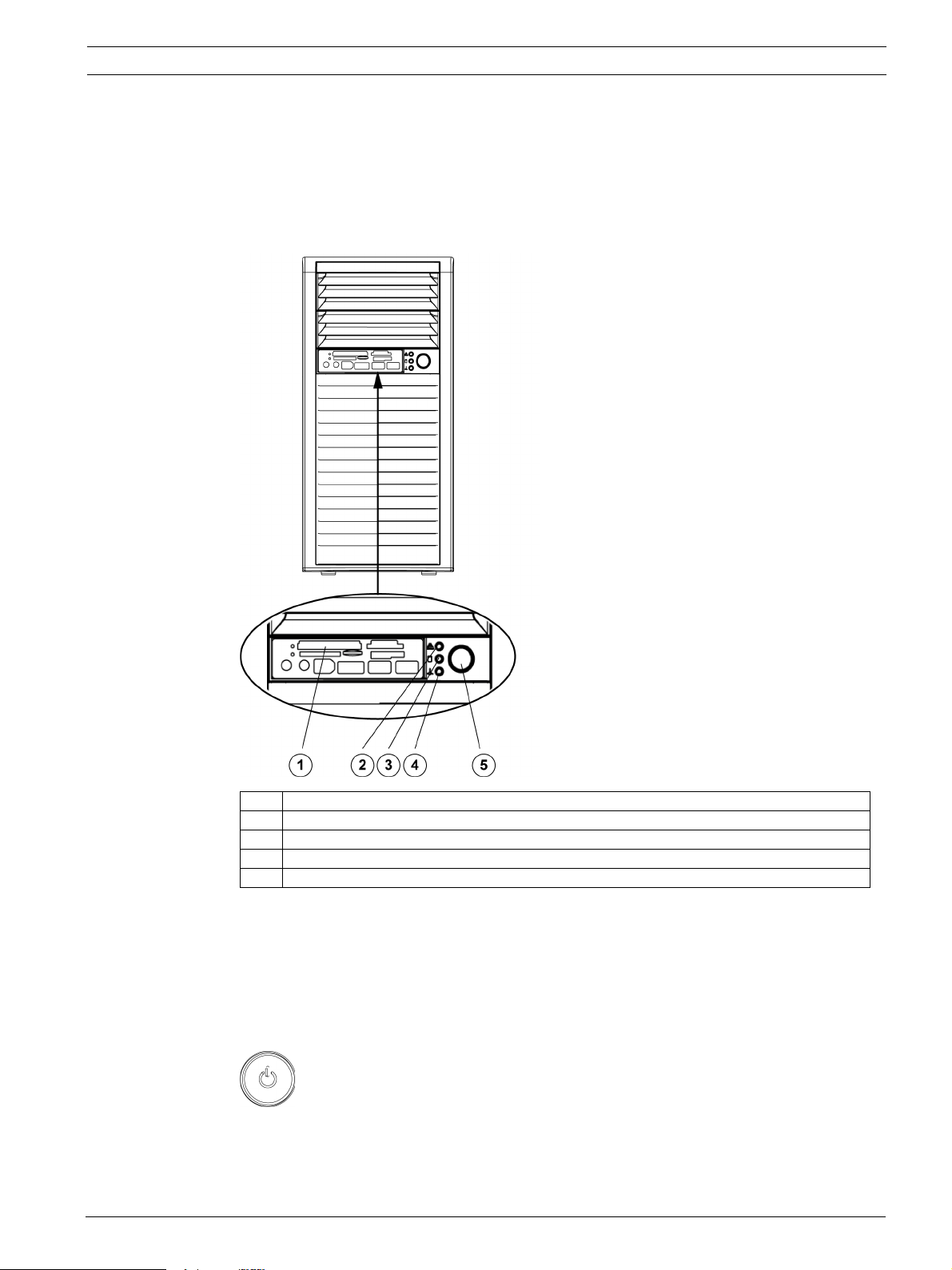
3 System Interface
There are several LEDs on the control panel as well as others on the drive carriers to keep you
constantly informed of the overall status of the system as well as the activity and health of
specific components. The 1200 Series has a power on/off switch, located on the control
panel. This chapter explains the meanings of all LED indicators and the appropriate responses
you may need to take.
1 All-in-One Card Reader
2NIC LED
3 HDD LED
4 OH LED
5 Power Button
3.1 Control Panel Buttons
Power: The main power button is used to apply or remove power from the power supply to
the system. When the power is on, the power button will be lighted by a blue LED. Turning off
the system power with this button will cause the blue LED to turn off and will remove the
main power, but will keep standby power supplied to the system. Therefore, you must unplug
system before servicing the system.
3.2 Control Panel LEDs
The control panel located on the front of the 1200 Series chassis has three LEDs. These LEDs
provide you with critical information related to different parts of the system. This section
Bosch Sicherheitssysteme GmbH Installation Manual DOC | V1 | 2010.08

8 en | System Interface 1200 Series IP Video Storage System
explains what each LED indicates when illuminated and any corrective action you may need to
take.
HDD: Indicates IDE channel activity. SAS/SATA drive activity when flashing.
NIC1: Indicates network activity on GLAN1 / 2 when flashing.
Overheat/Fan Fail: This LED indicates a fan failure when flashing.
When Continuously On (not flashing): This LED indicates an overheat condition caused by
cables obstructing the airflow in the system or the ambient room temperature being too
warm.
Correcting an Overheat/Fan Fail Condition
1. Check the routing of the cables and move any cables the restrict airflow.
2. Confirm that all fans are operating normally.
3. Verify that the heatsinks are installed properly.
4. If the chassis cover is not aligned correctly, the airflow may be disrupted. This leads to
overheating. Confirm that the chassis cover is placed correctly.
5. This LED will remain active as long as the overheat condition exists.
DOC | V1 | 2010.08 Installation Manual Bosch Sicherheitssysteme GmbH
 Loading...