

Page 1
D7032 Eight-Zone LED Annunciator Expander
s
Installation Guide
1.0 Notice
These instructions cover the installation of the D7032 Eight-Zone LED Annunicator Expander in a fire system
supervised by a D7024 Fire Alarm Control Panel (FACP).
Install, test and maintain the D7032 according to these instructions, NFPA 72, Local Codes and the Authority Having
Jurisdiction (AHJ). Failure to follow these instructions may result in failure of the device to operate properly. Bosch
Security Systems, Inc. is not responsible for improperly installed, tested or maintained devices.
These instructions contain procedures to follow in order to avoid personal injury and damage to equipment.
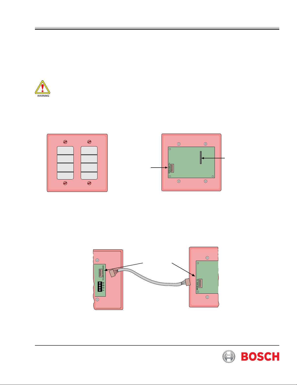
2.0 Device Description
The D7032 is an eight-zone LED Annunciator expansion module for use with the D7030X Series LED Annunciators.
Note: For proper operation of the D7030X LED Annunciator with the D7024 FACP, make sure that the panel firmware is
version 2.0 or greater.
1
9
To ANN-MAIN
Remote LED Pin
1-9
Front Outside Vi ew
Figure 1: D7032 Eight-Zone LED Annunciator Expander
Inside View
3.0 Installing the D7032
Note: Make sure all wiring is un-powered before routing. Annunciator wiring cannot be shared within the same cable with
multiplex, telephone or notification appliance wiring.
Use the supplied cable to connect the D7032 to the D7030X. See Figure 2 for details.
Install Cable
D7030X
Figure 2: Connecting the D7032 to the D7030X
Note: The D7032 must be mounted within 20 ft. (6 m), and in the same room as the D7030X LED Annunciator. All wiring must
be in conduit.
D7032
Page 2
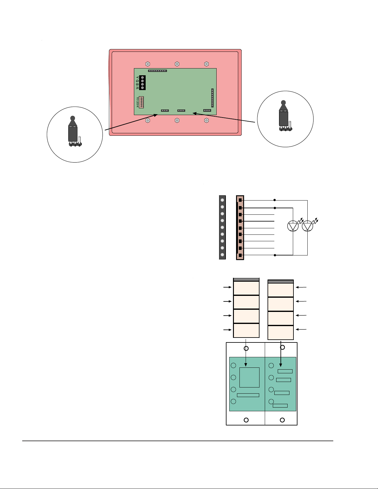
Set the LED jumpers on the D7030X as shown in Figure 3 for operation with the D7032.
J
R
TOP
5
6
7
8
Note: Set jumpers for 16 LEDs ENABLED and 16 ZONES.
D7030X
16 LED 8 LED 16 LED ENABLE
16 LED 8 LED
umper setting for 16 ZONES
Figure 3: Jumper Settings
4.0 Adding Remote LEDs
External LEDs for remote indication of the
individual zones may be added by connecting to
the remote LED pins as shown in Figure 4.
Note: Pins 1-8 correspond to D7032 LEDs 1-8 (Zones
9-16).
Note: The current draw for the remote LEDs for any zone
cannot exceed 6 mA.
5.0 Mounting the D7032
The D7032 should be mounted to the right of the
D7030X and at entry locations in plain view.
Remove the faceplate.
Note: Before mounting the D7032 to the back box, the
zone labels need to be marked and inserted into
their respective slots.
Once the labels are in place, mount the D7032 to
the back box. Then place the faceplate in position.
Use the supplied screws to secure the D7032 in
the back box.
TO CTRL-X
16 LED ENABLE
Jumper setting for
16 LEDs ENABLED
emote LED Pins
on D7032
1
9
Cable Harness
BROWN
RED
ORANGE
YELLOW
GREEN
BLUE
VIOLET
GRAY
BLK
Figure 4: External LED Connections
Zone #1
Zone #2
Zone #3
Zone #4
FIRST
FLOOR
SECOND
FLOOR
THIRD
FLOOR
FOURTH
FLOOR
TOP
BASEMENT
GYM ONE
GYM TWO
STORAGE
AREA
Zone #
Zone #
Zone #
Zone #
6.0 D7032 Specifications
• Control Panel Requirements: Compatible with the
D7024 FACP with version 2.0 or greater firmware
installed.
• Operating Volt age: 12 VDC Nominal
• Standby Current: 35 mA
• Alarm Current: 175 mA
• Width: 4.5 in. (11.4 cm)
• Height: 4.5 in. (11.4 cm)
• Depth: 1.5 in. (3.8 cm)
Figure 5: Label Installation
Bosch Security Systems, Inc.
130 Perinton Parkway
Fairport, NY, USA 14450-9199
(800) 289-0096
Copyright © 2007 Bosch Security Systems, Inc.
D7032 Installation Inguide
P/N: F01U071477-01 7/07 Page 2
 Loading...