

D7030X-S2
Installation Guide
EN
Eight-Zone LED
Annunciator
D7030X-S2 | Installation Guide |
Notices
Notices
This guide covers the installation of the D7030X-S2 Eight-Zone LED Annunicator in a fire system supervised by a
D7024 Fire Alarm Control Panel (FACP).
Install, test, and maintain the D7030X-S2 according to this guide, NFPA 72, local codes, and the Authority Having
Jurisdiction (AHJ).
Follow the procedures in this guide to avoid personal injury and damage to the equipment. Failure to
follow procedures can cause the D7030X-S2 to not operate properly. Bosch is not responsible for
improperly installed, tested, or maintained devices.
1.0 Description
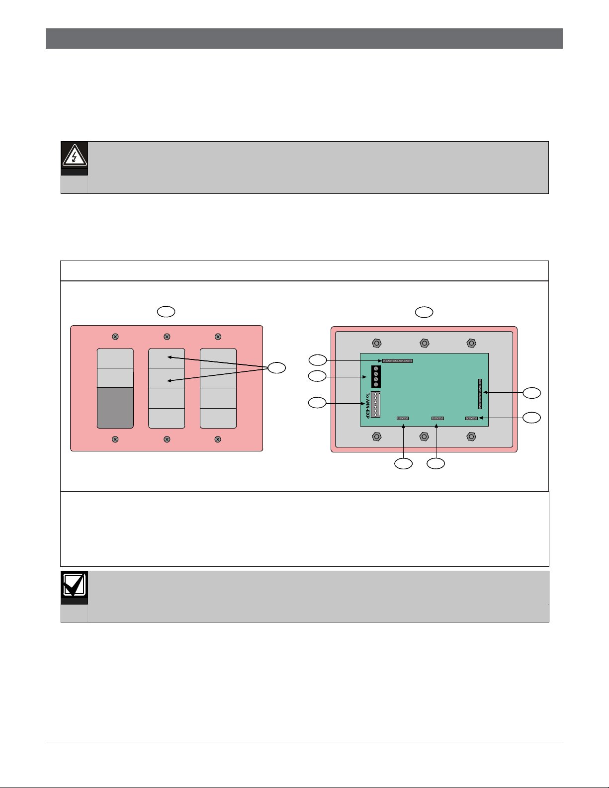
Two of the D7030X-S2’s eight zones are reserved for supervisory functions. This annunciator has power, trouble, and
eight zone LEDs that can be individually labeled. The D7030X-S2 mounts in a standard three-gang box (Figure 1).
Figure 1: D7030X-S2 Features
POWER
ON
SYSTEM
TROUBLE
FIRE SYSTEM
ANNUNCIATOR
1
2
10
9
8
18
Y
G
B
R
16 LED 8 LED
3
16 LED ENABLE
7
1 - Front outside view 6 - LED enable jumpers
2 - Yellow supervisory LEDs (2) 7 - 8 and 16 zone selection
3 - Inside view 8 - To D7032 (optional)
4 - Address jumpers 9 - To FACP option bus
5 - To D7031 (optional) 10 - Remote LED pins
For the D7030X-S2 to operate with the D7024, use control panel firmware version 2.0 or greater.
8
4
1
To CTRL-X
6
5
Bosch | 11/04 | 48177D2
D7030X-S2 | Installation Guide | 4.0 Wiring
2.0 Setting the Address
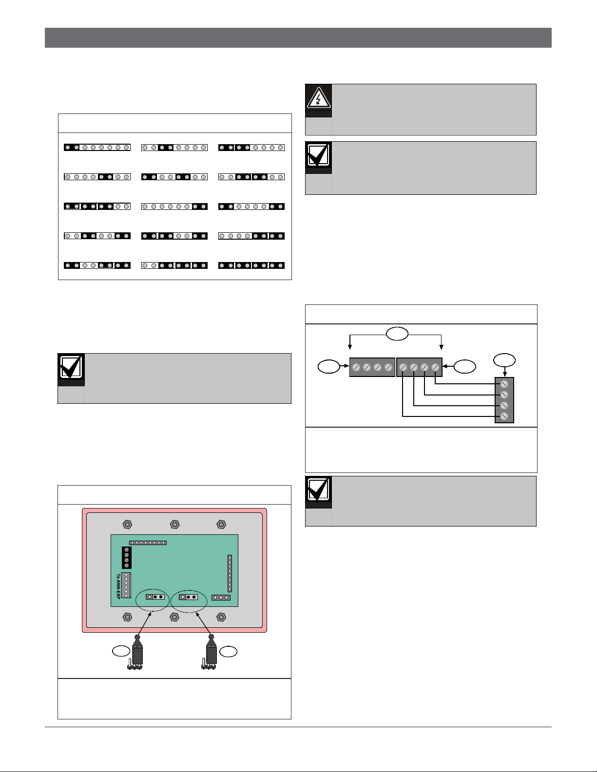
Figure 2 shows the fifteen annunciator addresses you can
select from when setting the D7030X-S2 address.
Figure 2: Address Settings
Address 1
1 | 2 | 4 | 8
Address 4
1 | 2 | 4 | 8
Address 7
1 | 2 | 4 | 8
Address 10
1 | 2 | 4 | 8
Address 13
1 | 2 | 4 | 8
Address 2
1 | 2 | 4 | 8
Address 5
1 | 2 | 4 | 8
Address 8
1 | 2 | 4 | 8
Address 11
1 | 2 | 4 | 8
Address 14
1 | 2 | 4 | 8
Address 3
1 | 2 | 4 | 8
Address 6
1 | 2 | 4 | 8
Address 9
1 | 2 | 4 | 8
Address 12
1 | 2 | 4 | 8
Address 15
1 | 2 | 4 | 8
The D7030X-S2 must have a unique address set within
its address pins. This address cannot conflict with other
annunciator addresses or other option bus device
addresses. Program the D7030X-S2 at the control panel
using the Update Bus option in the Programming Mode.
Each address can only support one device.
3.0 Setting the LED Jumpers
Set the LED jumpers to 8 LED (zones) and 8 LED
ENABLED as shown in Figure 3. When adding a D7032
Eight-Zone LED Expander, refer to the D7032
Installation Guide (P/N: 47169) for jumper settings.
Figure 3: Jumper Settings
4.0 Wiring
Ensure all wiring is de-energized before
routing.
Inform the operator and local AHJ before
installing the D7030X-S2 in an existing
1. Remove AC power from the system at the dedicated
2. Remove the standby battery power before making
3. Route the wiring from the control panel (Option
Figure 4: D7030X-S2 Terminal Wiring
1 - Control panel option bus 3 - Option Bus B
2 - Option Bus A 4 - Terminal strip
Note: Connect to either bus.
system. Also, disconnect all power to the
FACP.
120 VAC breaker.
or removing any connections to the FACP.
Bus A or Option Bus B) through the three-gang box
knockout and to the annunciator terminal strip
(Figure 4).
1
RABA GA YA
2 3
RBBBGB YB
4
Y
G
B
R
To prevent the D7030X-S2 from operating
improperly, do not use Bus A and Bus B
simultaneously. Use one or the other.
18
Y
G
B
R
16 LED 8 LED
1
16 LED 8 LED
16 LED ENABLE
16 LED ENABLED
8
1
To CTRL-X
2
1 - 16 LED 8 LED (jumper setting for 8 zones)
2 - 16 LED ENABLED (jumper setting for 8 LEDs
enabled)
3Bosch | 11/04 | 48177D
 Loading...