

Page 1
D7030X
Installation Guide
EN
Eight-Zone LED
Annunciator
Page 2
D7030X | Installation Guide |
Notices
Notices
This guide covers the installation of the D7030X Eight-Zone LED Annunicator in a fire system supervised by a
D7024 Fire Alarm Control Panel (FACP).
Install, test, and maintain the D7030X according to the procedures in this guide, NFPA 72, local codes, and the
Authority Having Jurisdiction (AHJ).
Follow the procedures in this guide to avoid personal injury and damage to the equipment. Failure to
follow procedures can cause the D7030X to not operate properly. Bosch is not responsible for
improperly installed, tested, or maintained devices.
1.0 Description
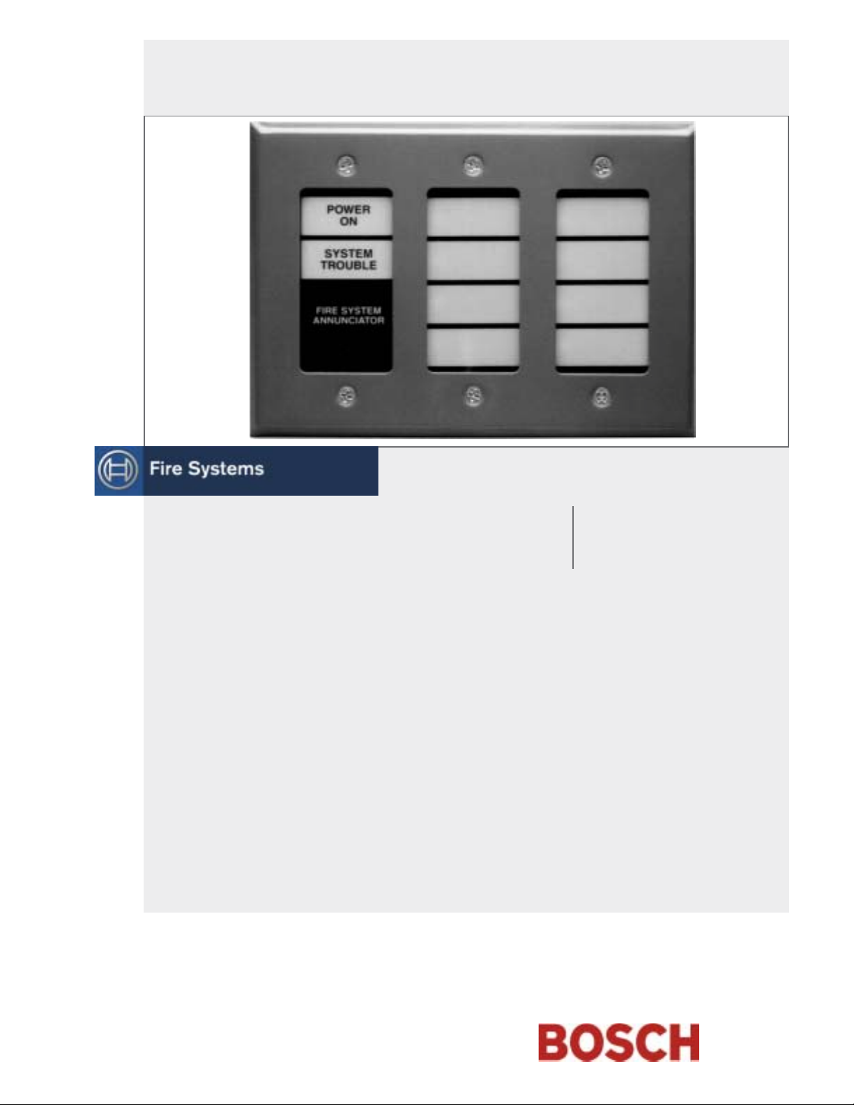
The D7030X has power, trouble, and eight-zone LEDs that can be individually labeled. Mount the D7030X in a
standard three-gang box (Figure 1).
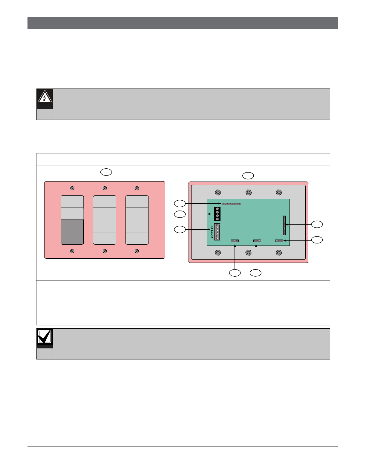
Figure 1: D7030X Features
POWER
ON
SYSTEM
TROUBLE
FIRE SYSTEM
ANNUNCIATOR
1
9
8
18
Y
G
B
R
7
16 LED 8 LED 16 LED ENABLE
2
6
5
1 - Front outside view 6 - 8 and 16 zone selection
2 - Inside view 7 - To D7032 (optional)
3 - Address jumpers 8 - To FACP option bus
4 - To D7031 (optional) 9 - Remote LED pins
5 - LED enable jumpers
For the D7030X to operate with the D7024, use control panel firmware version 2.0 or greater.
To CTRL-X
8
3
1
4
Bosch | 11/04 | 47292E2
Page 3
D7030X | Installation Guide | 4.0 Wiring
Ensure all wiring is de-energized before
routing.
Inform the operator and the local AHJ before
installing the D7030X in an existing system.
Disconnect all power to the FACP.
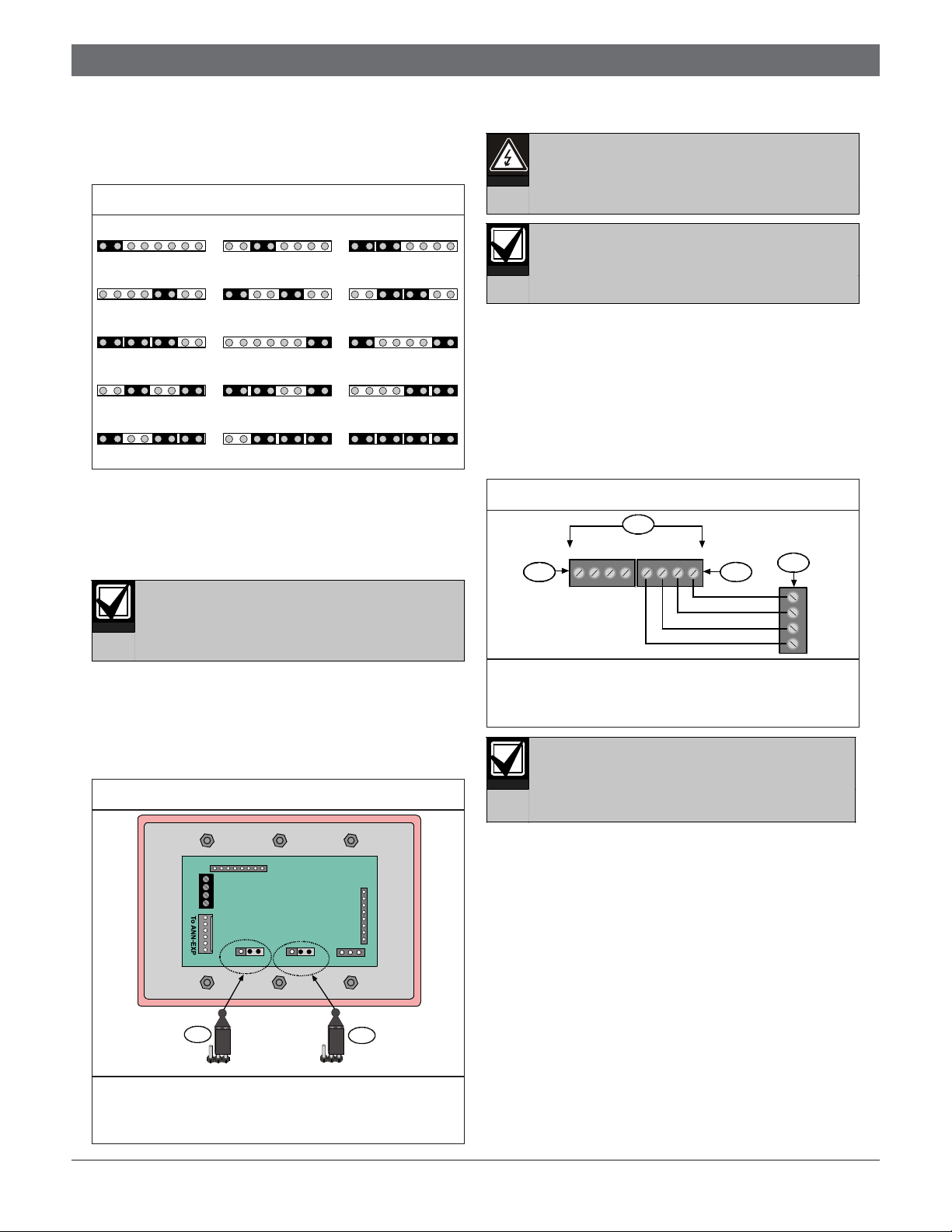
2.0 Setting the Address
Figure 2 shows the 15 possible annunciator addresses you
can select when setting the D7030X address.
Figure 2: Address Settings
Address 1
1 | 2 | 4 | 8
Address 4
1 | 2 | 4 | 8
Address 7
1 | 2 | 4 | 8
Address 10
1 | 2 | 4 | 8
Address 13
1 | 2 | 4 | 8
The D7030X must have a unique address set within its
address pins. This address cannot conflict with other
annunciator addresses or other option bus device
addresses. Program the D7030X at the control panel
using the Update Bus option in the Programming Mode.
Each address can only support one device.
Address 2
1 | 2 | 4 | 8
Address 5
1 | 2 | 4 | 8
Address 8
1 | 2 | 4 | 8
Address 11
1 | 2 | 4 | 8
Address 14
1 | 2 | 4 | 8
Address 3
1 | 2 | 4 | 8
Address 6
1 | 2 | 4 | 8
Address 9
1 | 2 | 4 | 8
Address 12
1 | 2 | 4 | 8
Address 15
1 | 2 | 4 | 8
4.0 Wiring
1. Remove the AC power from the system at the
dedicated 120 VAC breaker.
2. Remove the standby battery power before making
or removing any connections to the FACP.
3. Route wiring from the control panel (Option Bus A
or Option Bus B) through the three-gang box
knockout to the annunciator terminal strip
(Figure 4).
Figure 4: D7030X Terminal Wiring
1
RABAGA YA
2 3
RBBBGBYB
4
Y
G
B
R
3.0 Setting the LED Jumpers
Set the LED jumpers to 8 LED (zones) and 8 LED
ENABLED as shown in Figure 3. When adding a D7032
Eight-Zone LED Expander, refer to the D7032
Installation Guide (P/N: 47169) for jumper settings.
Figure 3: Jumper Settings
18
Y
G
B
R
16 LED 8 LED
16 LED ENABLE
1
16 LED 8 LED
16 LED ENABLED
1 - 16 LED 8 LED (jumper setting for 8 zones)
2 - 16 LED ENABLED (jumper setting for 8 LEDs
enabled)
8
1
To CTRL-X
2
1 - Control panel option bus 3 - Option Bus B
2 - Option Bus A 4 - Terminal strip
Note: Connect to either bus.
To prevent the D7030X from operating
improperly, do not use Option Bus A and
Option Bus B simultaneously. Use one or
the other.
3Bosch | 11/04 | 47292E
Page 4

D7030X | Installation Guide |
5.0 Adding External LEDs
4. Follow the wiring guidelines:
• Do not use shielded cable.
• Do not exceed 1000 ft (305 m) between the
FACP and the annunciator.
• Multiple home-runs are permitted but the total
length of annunciator wiring is limited to a
maximum of 4000 ft (1219 m) per system,
depending on the total current draw on the
branches (Table 1).
Table 1: Current Draw and Wire Gauge
Restrictions
Total Current Draw
on Branch
175 mA 4000 ft (1219 m)
200 mA 3500 ft (1065 m)
250 mA 3000 ft (915 m)
300 mA 2500 ft (760 m)
400 mA 1900 ft (580 m)
500 mA 1500 ft (455 m)
Maximum Length of
18 AWG (1.2 mm) Wire
You can use up to three annunciators on a single
500 ft (152 m) run of 18 AWG (1.2 mm) wire, or one
annunciator on a 1000 ft (305 m) run. Refer to the
D7032 Installation Guide (P/N: 47169) for more
information on cable length.
5. Refer to Section 6.0 Mounting on page 5 to mount the
D7030X.
6. Restore power to the system.
7. When wiring is complete, ensure the three-gang box
is secured to the mounting surface.
5.0 Adding External LEDs
You can add external LEDs for remote indication of the
individual zones by connecting to the remote LED pins
(Figure 5).
Figure 5: External LED Connections
1
1
8
2
4
5
6
7
8
9
10
11
1 - Remote LED pins 7 - Yellow wire
2 - Cable harness 8 - Green wire
3 - Remote LEDs 9 - Blue wire
4 - Brown wire 10 - Violet wire
5 - Red wire 11 - Gray wire
6 - Orange wire 12 - Option bus
Note: The remote LED pins are on the D7030X.
The current draw for remote LEDs for
any zone cannot exceed 6 mA.
3
12
Bosch | 11/04 | 47292E4
Page 5

D7030X | Installation Guide | 7.0 Programming
6.0 Mounting
Mount the D7030X in easily seen positions
1. Before mounting the D7030X in a standard
Figure 6: Zone Label Location
1 - Zone 1 5 - Zone 5
2 - Zone 2 6 - Zone 6
3 - Zone 3 7 - Zone 7
4 - Zone 4 8 - Zone 8
2. Set the annunciator in or over the three-gang box.
3. Position the faceplate.
4. Secure the D7030X to the box using the screws
5. Connect the standby batteries.
6. Close the 120 VAC dedicated breaker controlling
at entry locations.
three-gang box, mark the zone labels and insert
them into their respective slots (Figure 6).
POWER
ON
SYSTEM
TROUBLE
FIRE SYSTEM
ANNUNCIATOR
TOP
1
2
3
4
FIRST
FLOOR
SECOND
FLOOR
THIRD
FLOOR
FOURTH
FLOOR
TOP
BASEMENT
GYM ONE
GYM TWO
STORAGE
AREA
5
6
7
8
(supplied).
the power input to the control panel.
7.0 Programming
Program the D7030X by installing firmware
You can program zones to light whenever points within
that zone go into alarm. Do this by assigning an output
zone to each D7030X input point. For example, if you
assign Output Zone 1 to Input Points 1 through 5, the
LED for Output 1 lights when any input point in this
zone goes into an alarm.
1. Press [0/PROG] to access the Programming Mode.
2. Enter a personal identification number (PIN) if a
3. At the Programming Menu, press [3] for Prog
4. Press [4] for Option Bus.
5. With the D7030X connected to the option bus, press
6. Press [*/CLEAR] to return to the Programming
7. At the Programming Menu, press [4] for Prog
8. Press [1] for Point Number and enter the point
9. Press [#/CMND] to accept the entry.
10. Press [2] for Output Zone and enter the output zone
11. Repeat Steps 7 through 10 until all points are
12. Press [*/CLEAR] three times to exit the
version 2.0 or greater in the FACP.
PROG MODES appears across the top line and the
Programming Menu options scroll across the second
line.
prompt appears for this information.
System.
[1] for Update Bus.
The FACP indicates a device is added to the option
bus.
Menu.
Inputs.
number you want programmed.
for this point.
programmed.
Programming Menu and return to the Main Menu.
5Bosch | 11/04 | 47292E
Page 6

D7030X | Installation Guide |
9.0 Specifications
8.0 Using a D7032 with the D7030X
Each D7030X processes 16 zones of information. When a D7032 Eight-Zone LED Annunciator Expander is
connected to the D7030X, an additional 8 LED zones appear allowing the D7030X and D7032 combination to show
a total of 16 LED zones. If no D7032 is attached, only the lower 8 zones appear. Up to 8 D7030X and D7032
combinations can connect to the D7024 FACP.
Table 2 identifies the D7030X and D7032 combinations.
Table 2: D7030X and D7032 Combinations
D7030X Zones
Covered
1 1 to 16 1 to 8 9 to 16 Combination with lowest option bus address such as
2 17 to 32 17 to 24 25 to 32 Combination with second lowest option bus address such as
3 33 to 48 33 to 40 41 to 48 Combination with third lowest option bus address such as
4 49 to 64 49 to 56 57 to 64 Combination with fourth lowest option bus address such as
5 1 to 16 1 to 8 9 to 16 Fifth combination repeats first combination.
6 17 to 32 17 to 24 25 to 32 Sixth combination repeats second combination.
7 33 to 48 33 to 40 41 to 48 Seventh combination repeats third combination.
8 49 to 64 49 to 56 57 to 64 Eighth combination repeats fourth combination.
Note: The column labeled “Appears on D7030X” applies whether or not the D7032 is connected to any D7030X.
Appears on
D7030X
Appears on
D7032 (if
attached)
Comment
Address 1.
Address 2.
Address 3.
Address 4.
9.0 Specifications
Table 3: Specifications
Operating Voltage
Standby Current
Alarm Current
Dimensions (H x W x D)
Wire Type
Maximum Distance Allowed Between
Control Panel and Annunciators
Maximum Distance of Annunciator
Wire for each System
Number for each System
12 VDC nominal
35 mA (27 mA for battery calculation)
175 mA (132 mA for battery calculation)
4.5 in. x 6.5 in. x 0.75 in. (11.4 cm x 16.5 cm x 1.9 cm)
Non-shielded, four-wire
1000 ft (305 m)
4000 ft (1219 m)
Eight D7030X, eight D7032 maximum
Bosch | 11/04 | 47292E6
Page 7

Notes
D7030X | Installation Guide | Notes
7Bosch | 11/04 | 47292E
Page 8

Bosch
130 Perinton Parkway
Fairport, NY 14450-9199 USA
Customer Service: (800) 289-0096
Technical Support: (888) 886-6189
© 2004 Bosch
47292E
 Loading...