

Bosch D6680 Installation Instructions Manual
Available from A1 Security Cameras
www.a1securitycameras.com email: sales@a1securitycameras.com
Conettix D6680
Installation Instructions
EN
Ethernet Network
Adapter
Conettix D6680 | Installation Instructions | Trademarks
Available from A1 Security Cameras
www.a1securitycameras.com email: sales@a1securitycameras.com
Trademarks
Microsoft® Windows® 98SE, Windows® ME, Windows
2000, Windows
either registered trademarks or trademarks of Microsoft
Corporation in the United States and/or other
countries.
®
NT, MS-DOS
®,
and Windows® XP are
®
2
Bosch Security Systems, Inc. | 5/07 | 4998138732-01

Conettix D6680 | Installation Instructions | Contents
Available from A1 Security Cameras
www.a1securitycameras.com email: sales@a1securitycameras.com
.
Contents
1.0 Introduction.......................................................4
1.1 Network Interface...............................................4
1.2 Serial Interface....................................................4
2.0 Installation .........................................................5
2.1 All Installations................................................... 5
2.2 UL Installations Fire Alarm Applications........5
2.3 Mounting in a Separate Enclosure ...................5
2.4 D8004 Transformer Enclosure..........................6
3.0 Configuration and Programming.................6
3.1 Factory Default IP Address ...............................6
3.2 Identifying the MAC Hardware Address ........7
3.3 Obtaining an IP Address ...................................7
3.4 Initial Assignment of the IP Address using
ARP......................................................................7
3.4.1 ARP Command Usage.......................................8
3.5 Using Telnet to Finish the Configuration........ 8
3.5.1 Using Telnet with Windows 98SE or ME .......8
3.5.2 Using Telnet with Windows NT,
Windows 2000, or Windows XP.....................12
3.6 Programming Overview for the D6600.........12
3.7 Configuring for Network Communication
Using a D6680 ..................................................13
3.8 Editing Program Parameters ...........................14
4.0 Specifications ..................................................15
Tables
Table 1: D6680 Default IP Address ............................... 6
Table 2: Netmask Address ............................................ 10
Table 3: Specifications ................................................... 15
Figures
Figure 1: Network Interface........................................4
Figure 2: RJ-45 Ethernet Jack Pinouts....................... 4
Figure 3: Serial Interface.............................................4
Figure 4: 25-pin Serial Port.........................................4
Figure 5: Mounting Holes for D6680........................5
Figure 6: D6680 in an AE1/AE2 Enclosure .............5
Figure 7: D8004 Installation .......................................6
Figure 8: D6680 Label.................................................7
Figure 9: Command Syntax........................................7
Figure 10: MS-DOS Prompt.........................................8
Figure 11: Telnet Session ............................................10
Figure 12: Telnet session – Gateway Address ..........10
Figure 13: D6680 Encryption.....................................11
Figure 14: Command Prompt - telnet .......................12
Figure 15: Port Value Change....................................12
Bosch Security Systems, Inc. | 5/07 | 4998138732-01
3
Conettix D6680 | Installation Instructions | 1.0 Introduction
Available from A1 Security Cameras
www.a1securitycameras.com email: sales@a1securitycameras.com
1.0 Introduction
The Bosch Security Systems, Inc. Conettix D6680
Ethernet Network Adapter (referred to as the D6680) is
a two-channel network adapter. The D6680 includes a
cable for connecting to the DB25 Channel 1 Port. For
most networked installations, only one channel needs
to be used and configured.
Follow these instructions to avoid the
possibility of harm to the operator, or
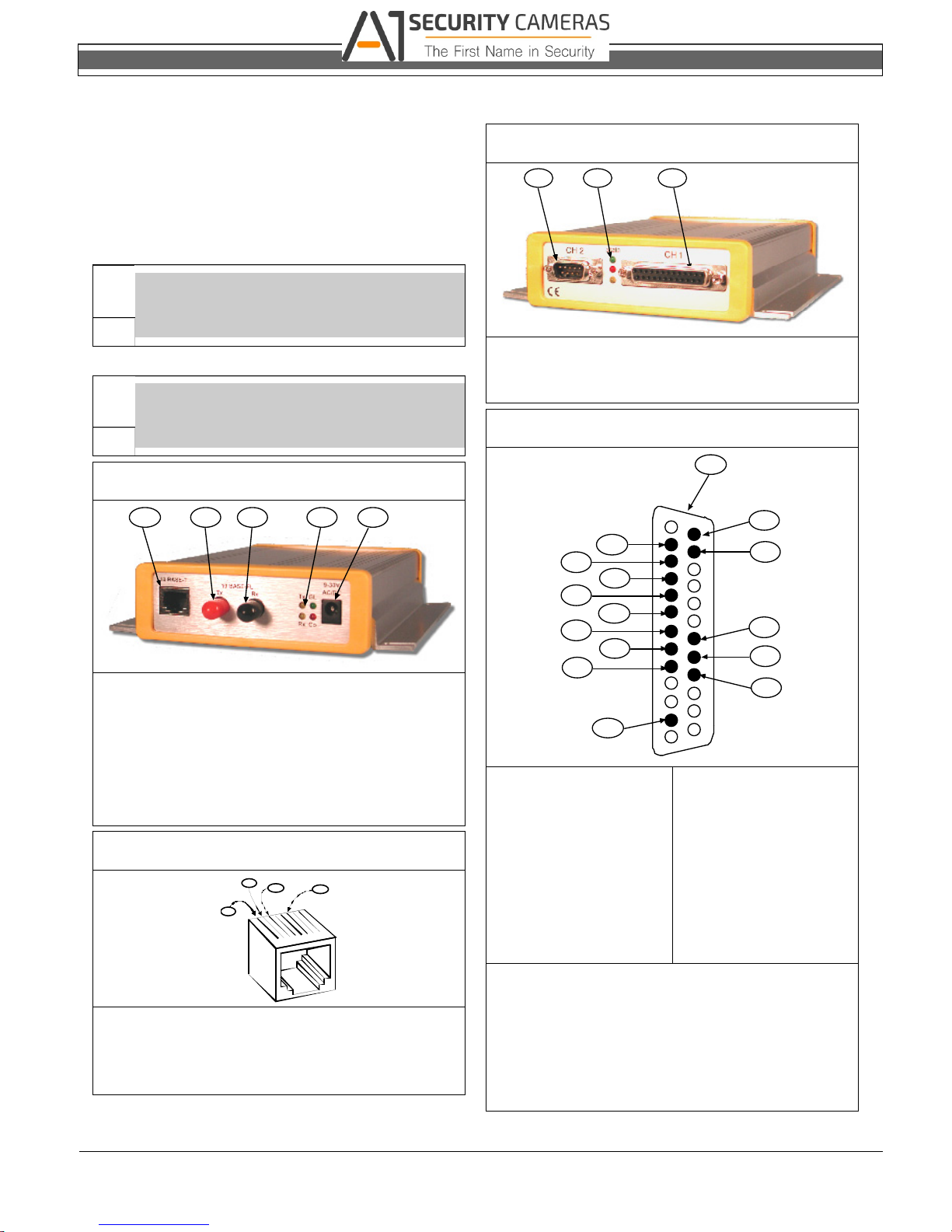
1.1 Network Interface
Figure 1: Network Interface
1 - 10BASE-T Ethernet port (refer to Figure 2)
2 - 10BASE-FL Ethernet port (transmit) –
Not Used
3 - 10BASE-FL Ethernet port (receive) –
Not Used
4 - Network LEDs
5 - Power plug
Figure 2: RJ-45 Ethernet Jack Pinouts
1 - TX+
2 - TX3 - RX+
6 - RX-
damage to the program or equipment.
Do not attempt to connect both Ethernet
ports simultaneously. The D6680 does not
have routing capabilities.
1 2
3 4 5
2
3
6
1
1.2 Serial Interface
Figure 3: Serial Interface
1 2 3
1 - DB9 Serial port (DTE) – Not Used
2 - Serial LEDs
3 - DB25 Serial port (DCE) (refer to Figure 4)
Figure 4: 25-pin Serial Port
1
1
15
14
13
12
11
10
9
8
7
13
1 - RS-232C 9 - DCD (out)
*
2 - TX+ (out)
3 - TX – (out)
*
4 - DTR + (in)
*
5 - RX + (in)
6 - RX – (in)
7 - Reg +9-30 VDC
8 - Reg +5 VDC
*
The minus sign (-) is sometimes represented as
*
**
**
A (such as TXA).
The plus sign (+) is sometimes represented as
B (such as TXB).
**
The device server can be powered up
alternately through the serial port and one of
these pins.
14
2
3
4
5
6
25
10 - GND
11 - DSR (out)
12 - CTS (out)
13 - RTS (in)
14 - RX (out)
15 - TX (in)
4
Bosch Security Systems, Inc. | 5/07 | 4998138732-01
.
Available from A1 Security Cameras
www.a1securitycameras.com email: sales@a1securitycameras.com
2.0 Installation
2.1 All Installations
Install the Conettix D6600 Communications
Receiver/Gateway (referred to as the D6600) according
to NFPA 70, NFPA 72, and the local authority having
jurisdiction (AHJ).
Conettix D6680 | Installation Instructions | 2.0 Installation
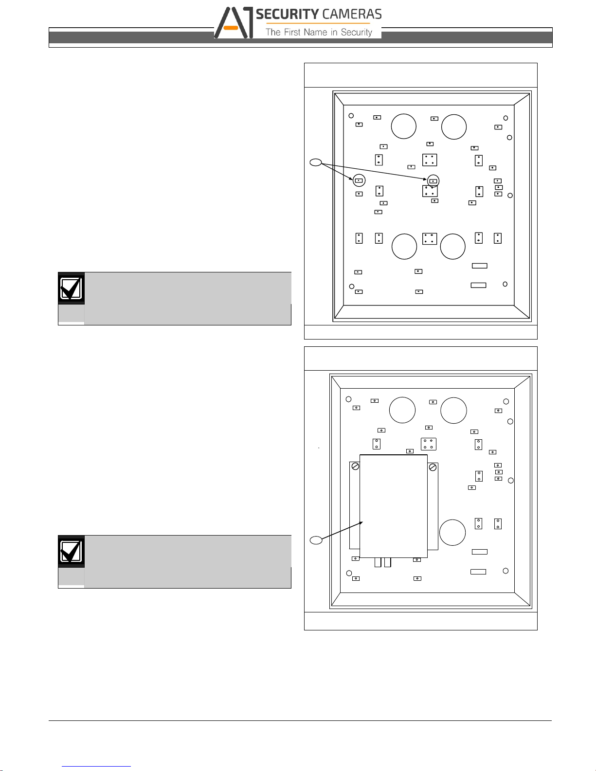
Figure 5: Mounting Holes for D6680
2.2 UL Installations Fire Alarm
Applications
The D6680 is suitable for Central Station Protective
Signaling when it is installed and used in compliance
with NFPA 72 and ANSI/NFPA 70. Installation limits
for digital alarm communicator receivers (DACR) are
under the jurisdiction of your local AHJ.
The D6680 must be installed in the same room as the
D6600 and within 15.2 m (50 ft) of the D6600.
For UL Listed Fire Installations, equipment
between Ethernet Interface Modules and
the D6680 is required to be UL Listed
Information Technology Equipment.
2.3 Mounting in a Separate Enclosure
Required for UL Central Station Protective Signaling,
the D6680 must be mounted in a separate enclosure
such as the AE1 (gray) or the AE2 (red).
Before installing the D6680 in the AE1 or AE2
enclosure, find the correct mounting holes on the back
wall of the enclosure. Only these holes align correctly
for securing the D6680 with two screws.
When you locate the holes, mount the D6680:
1. Place the D6680 against the back wall of the
enclosure.
2. Align the side mounting holes on the D6680 with
the enclosure mounting holes indicated in Figure 5.
3. Insert the two screws provided and slowly tighten
them until the D6680 is securely mounted to the
enclosure (refer to Figure 6).
Mount the enclosure on a vertical surface
before installing the module. All wires
within the enclosure are power limited and
supervised.
1
1 - Use these mounting holes.
Figure 6: D6680 in an AE1/AE2 Enclosure
1
Bosch Security Systems, Inc. | 5/07 | 4998138732-01
1 - D6680
5
 Loading...