

Page 1
Conettix D6672
EN
Installation Instructions
COM1 Expansion Kit
Page 2
D6672 | Installation Instructions | 1.0 Introduction
1.0 Introduction
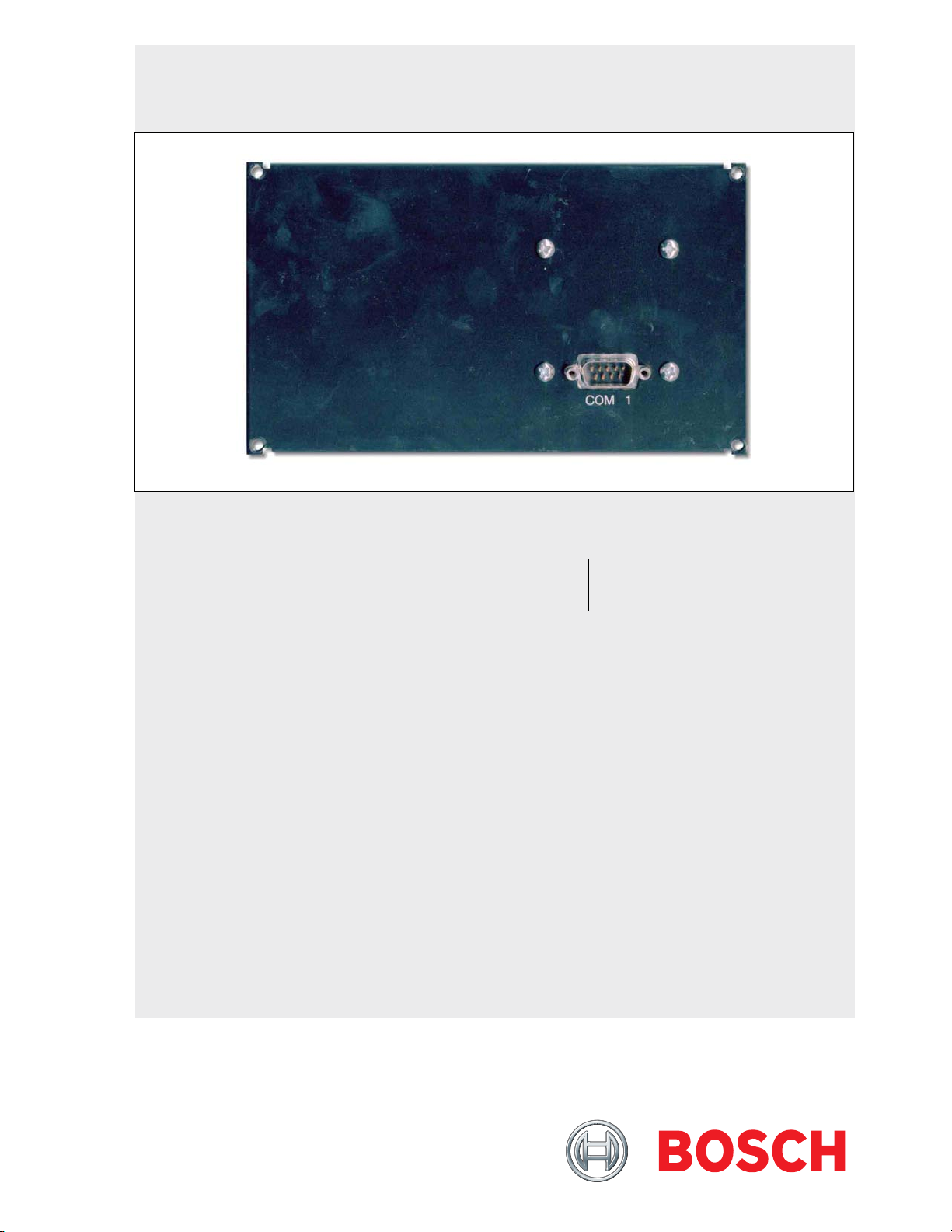
The Conettix D6672 COM1 Expansion Kit (Figure 1)
provides the Conettix D6600 Communications
Receiver/Gateway with an RS-232 interface port
connection to a Conettix D6680/D6682 Ethernet
Network Adapter for Network Communications. Used
in a network system, the D6672 allows connection to
an Ethernet local area network (LAN) or wide area
network (WAN).
Figure 1: D6672 COM1 Expansion Kit
COM 1
2.0 Installation
For additional information, refer to the Conettix D6600
Operation and Installation Guide (P/N: 4998122704).
Figure 2: D6600 Internal Features
1
9
8
1 - Telephone Line Card Terminators (D6645)
2 - Backplane
3 - CPU Terminator Card (D6615)
4 - AC/DC Power Supply (D6630)
5 - CPU Card (D6610)
6 - COM1 Cable
7 - DC/DC Power Supply (D6631)
8 - Card Guides
9 - Telephone Line Card (D6640/D6641)
2
3
4
5
6
7
2 Bosch Security Systems, Inc. | 1/09 | 4998122715-02
Page 3
.
2.1 Wiring
When connecting the D6672 to the D6682
Ethernet Network Adapter, use the cable
supplied with the D6682.
For UL installations:
- The D6682 and the D6600 must be
installed on the same mounting rack.
- The cable running between the
D6680/D6682 and the D6672 must be
in metal conduit and no longer than 20 ft
(6 m) if the COM1 is used in a network
system.
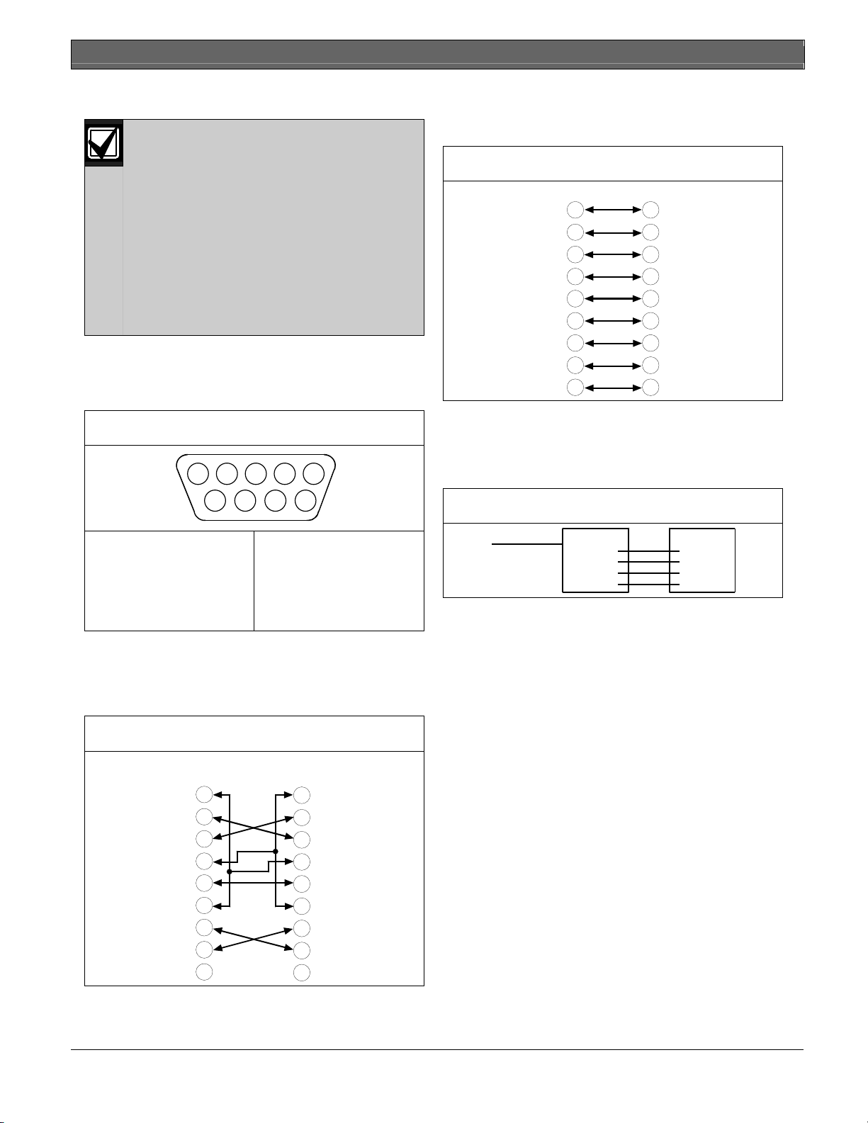
2.1.1 COM1 DB9 Connector
The COM1 Port uses a standard DB9 male connector.
Refer to Figure 3.
Figure 3: DB9 Male Connector
1 2 3 4 5
6 7 8 9
1 - DCD
2 - RX
3 - TX
4 - DTR
5 - SIG END
When connecting data terminal equipment together
(for example COM1 port to PC serial port), a null
modem cable is required. Refer to Figure 4 on page 3
for one possible configuration for a null modem cable.
6 - DSR
7 - RTS
8 - CTS
9 - RI
D6672 | Installation Instructions | 2.0 Installation
When connecting data terminal equipment to data
communication equipment (Figure 5), a modem cable
(for example, straight-through cable) is required.
Figure 5: COM1 Port to the D6680 (Channel 1)
DTE DCE
20
22
8
3
2
7
6
4
5
1
2
3
4
5
6
7
8
9
2.1.2 COM1 to CPU Card Cable
The pinouts for the 4-pin cable that connects the
COM1 Expansion Kit with the CPU Card are shown
in Figure 6.
Figure 6: Pinouts for COM1 to CPU
COM 1
1
Black
2
Yellow
3
Green
4
Red
GND
NA
Tx
Rx
CPU Card
GND
NA
Tx
Rx
Figure 4: COM1 Port to PC Serial Port
DTE
DB-9 Pin
1
2
3
4
5
6
7
8
9
DTE
DB-9 Pin
1
2
3
4
5
6
7
8
9
Bosch Security Systems, Inc. | 1/09 | 4998122715-02 3
Page 4

D6672 | Installation Instructions | 2.0 Installation
2.2 Mounting
The blank plate is located on the rear of the D6600
(Figure 7).
Figure 7: Blank Plate on Rear of D6600
1
Detection Systems Inc.
Fairport N.Y. USA
1
ON
OFF
B
A
T
T
E
R
Y
Input:
85-264 AC
47-63 Hz
2.5 Amps
1 - Blank Plate
To correctly install the D6672 COM1 Expansion Kit:
1. Power down the D6600. Disconnect the leads from
the battery to remove battery power. Remove AC
power by unplugging the AC cord from the outlet.
2. Remove four screws from the blank plate. The
blank plate is the second plate from the left when
viewing the receiver from the rear (Figure 7).
3. Connect COM1 connector cable to the 4-pin
connector on the inside of the COM1 plate
(Figure 8).
2
3
4
4. Feed the cable through the back of the D6600.
Feed the cable as close to the front of the
D6600 as possible to avoid removing the
CPU card. Refer to Step 9 on page 5.
5. Align the COM1 plate with the screw holes at the
rear of the receiver. The COM1 9-pin connector
should be on the outside of the receiver.
6. Attach the COM1 plate to the receiver by inserting
the four screws at the corners of the plate and then
securing them to the holes.
Figure 9: Attaching COM1 Plate to Rear of
D6600
2
1
4
Figure 8: Connecting to 4-pin Connector on the
D6672
1
6
5
4
3
1 - COM1 Plate
2 - COM1 Connector
Cable
3 - Red
4 - Green
5 - Yellow
6 - Black
2
The connector on the D6672 is keyed so
that it can be attached only one way. The
black wire should be on top.
3
1 - COM1 Plate
2 - Mounting Holes
3 - Mounting Screws (4)
4 - Plate Corners (4)
7. Pull the handle to open the front panel of the
D6600. Refer to Figure 10 on page 5.
Magnets hold the panel closed. When the
panel is opened, the inside of the D6600 is
visible.
4 Bosch Security Systems, Inc. | 1/09 | 4998122715-02
Page 5

D6672 | Installation Instructions | 2.0 Installation
.
Figure 10: D6600 with Front Panel Open
2
1
1 - Handle
2 - D6600 Front panel
8. The CPU card (Figure 11) is on the right side. The
4-pin connector is located at the bottom front
corner of the card.
The COM1 cable connects to the CPU Card.
Figure 11: Location of CPU Card
Figure 12: Sliding Out the CPU Card
1
2
1 - Plastic tab
2 - Slide card out
10. Push out the tabs on both sides of the blue ribbon
cable to disconnect the cable. Lift the cable
connector out. Refer to Figure 13.
Figure 13: Disconnecting the Ribbon Cable
1
2
1
1 - 4-pin connector
2 - CPU Card
9. If you cannot feed the COM1 cable to the front,
remove the CPU Card to connect the cable.
Pull the white plastic tab on the card (Figure 12 on
page 5) and slide the card out toward you.
2
1
1 - Tabs (2)
2 - Ribbon cable
11. Continue to slide out the card to allow more room
to grasp the end of the COM1 connector cable
(Figure 12).
12. Connect the other end of the COM1 connector
cable (Figure 14) to the 4-pin connector at the front
bottom corner of the CPU Card (Figure 11
on page 5).
Bosch Security Systems, Inc. | 1/09 | 4998122715-02 5
Page 6

D6672 | Installation Instructions | 2.0 Installation
If this is an unkeyed connector, ensure that
the red wire is on top closest to the ribbon
cable.
Figure 14: Connecting the Cable
4
3
2
1
1 - Black
2 - Yellow
3 - Green
4 - Red
14. Reconnect the blue ribbon cable by pushing down
on the connector until the tabs move inward
(Figure 15).
15. Slide the card back into the D6600 along the card
guides. Push on the plastic tab to firmly seat the
card.
When installation is complete, the rear of
the panel should resemble Figure 16.
Figure 16: Rear Panel of D6600 (with D6672
Installed)
Detection Systems Inc.
Fairport N.Y. USA
OFF
1
ON
B
A
T
T
E
R
Y
Input:
85-264 AC
47-63 Hz
2.5 Amps
2
3
1 - Conettix D6672 COM1 Expansion Kit
2 - Conettix D6615 CPU Terminator Card
3 - Conettix D6645 Line Terminator Card
To connect COM1 to the network, refer to
Section 2.3 Network Connection on page 7.
1
2
3
4
Figure 15: Reconnecting the Ribbon Cable
When reseating the CPU Card, align the
connectors correctly with the D6600
backplane to avoid bending the pins.
16. Close the front panel.
6 Bosch Security Systems, Inc. | 1/09 | 4998122715-02
Page 7

.
2.3 Network Connection
1. Connect a D6680/D6682 (optional) to COM1
(Figure 17). Use the straight modem cable provided
to connect to Channel 1 on the network adapter.
Figure 17: Location of COM1
Detection Systems Inc.
Fairport N.Y. USA
OFF
1
ON
B
A
T
T
E
R
Y
Input:
85-264 AC
47-63 Hz
2.5 Amps
2
D6672 | Installation Instructions | 3.0 Operation
3.0 Operation
Use the optional Conettix D6672 COM1 Expansion
Kit to minimize network traffic on the D6680/D6682
connected to COM4 (on the D6600). The D6672 can
communicate control panel messages and
programming from the D6200 Programming Software
using a network connection. COM4 operates the same
as COM1 but can also communicate the automation
1
2
3
4
output through the network connection.
4.0 Specifications
Table 1: Specifications
1 - COM1
2 - Rear of D6600
2. Use a CAT5e or CAT6 Ethernet cable to connect
the other end of the second network adapter to the
network hub.
3. Connect a PC with an Ethernet card to the
network using a CAT5e or CAT6 Ethernet cable.
This PC is connected to the network for
D6200 software applications and for
configuring the network adapters.
4. Apply power to the network adapters.
5. Using a PC connected to the network, configure
the network adapters through a telnet connection.
Refer to Configuration of the D6680/D6682 Network
Adapters in the Conettix D6600 Network System Guide
(P/N: 4998122712) for further details. Contact the
network administrator for assistance.
Voltage Range 12 VDC Nominal
Additional Battery
10 mA Current Required
Current
Additional Standby
2 mA
UPS Current
Dimensions (H x W x D) 4 in. x 6.8 in. x 0.75 in.
(10.2 cm x 17.3 cm x 19 mm)
Weight 3.9 oz (111 g)
Connectors
4-pin (from back of D6672 to
D6600 CPU Card)
9-pin RS-232 Port (from front
of D6672 to D6680/D6682)
Operating Temperature +32°F to 122°F (0°C to 50°C)
Bosch Security Systems, Inc. | 1/09 | 4998122715-02 7
Page 8

Bosch Security Systems, Inc.
130 Perinton Parkway
Fairport, NY 14450-9199
(800) 289-0096
© 2009 Bosch Security Systems, Inc.
4998122715-02
 Loading...