

Page 1
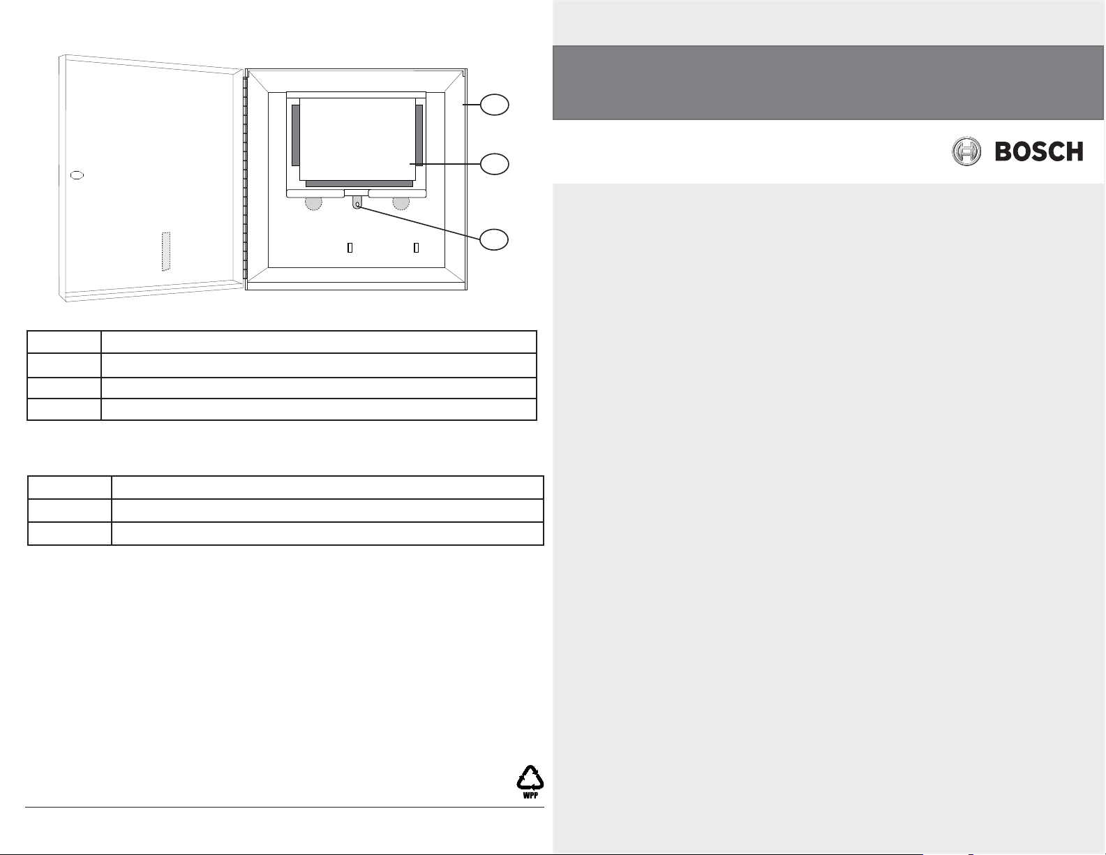
Figure 3: Completed assembly
Callout Description
1 Enclosure
2 Control panel
3 Lock-down tab
G Series Controls
D6103
1
2
en Installation Guide
3
2 Specifi cations
Dimensions (HxWxD) 14.18 in x 14.18 in x 3.1 in
Batteries Up to two D126 7amp hr
Lockset D101
Reading Bosch Security Systems, Inc. Product Date Codes
For Product Date Code information, refer to the Bosch Security Systems, Inc.
Web site at: http://www.boschsecurity.com/datecodes/.
© 2012 Bosch Security Systems, Inc. 130 Perinton Parkway Fairport, NY 14450
Page 2
1
2
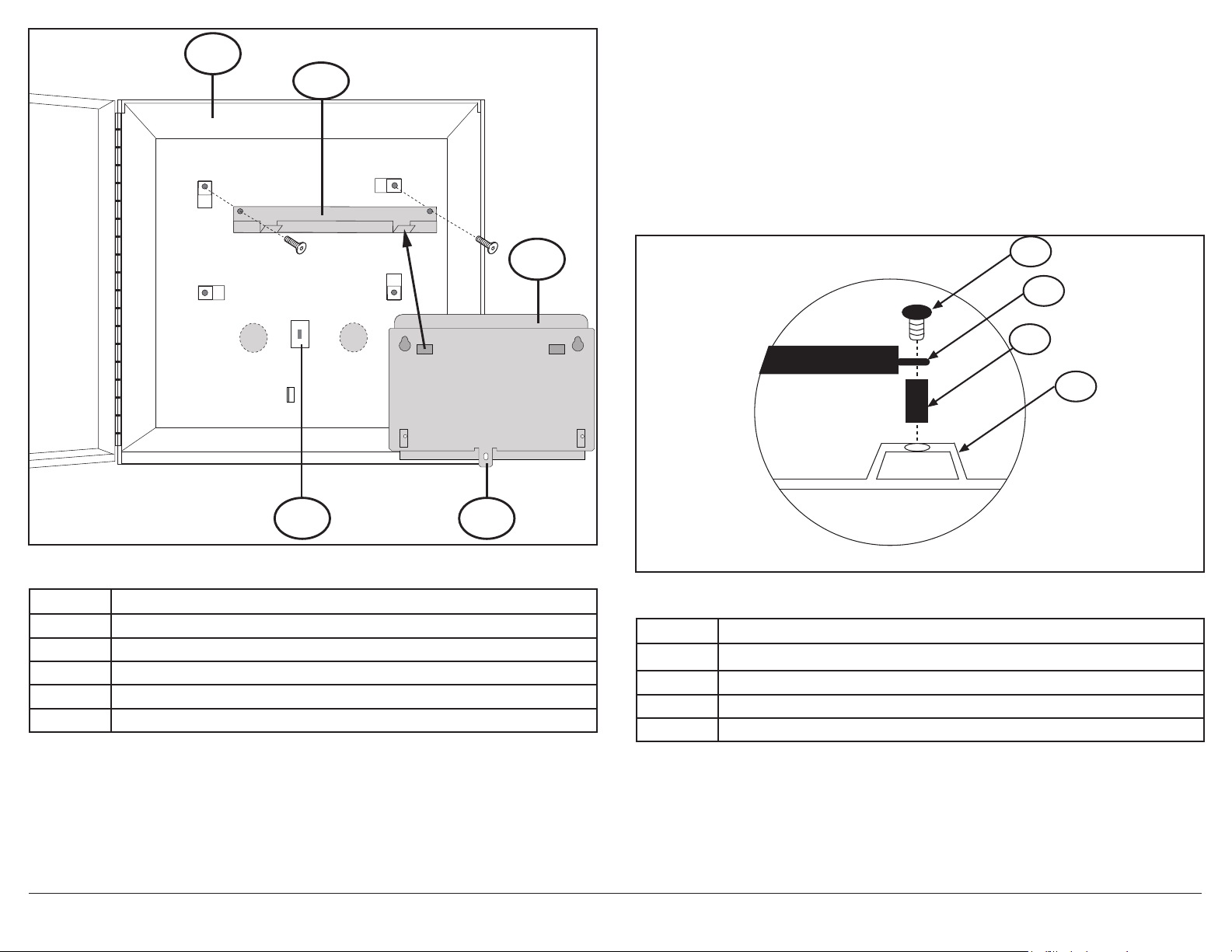
1 Installation
1. Install the mounting bracket included with the L901 kit as shown in
Figure 1.
2. Hang the mounting skirt on the mounting bracket by aligning the
rectangular openings on the back (top) of the mounting skirt with the
hooks on the mounting bracket as shown in Figure 1.
3. Secure the lock down tab on the mounting skirt to the support post
on the enclosure using the spacer and screw provided in the L901 kit.
(Figures 1 and 2)
Figure 1: D6103 Enclosure and Mounting Skirt
Callout Description
1 D6103 enclosure
2 Mounting bracket
3 Mounting skirt (back)
4 Lock down tab
5 Support post
3
1
2
3
4
5
4
Figure 2: Support post and lock-down tab
Callout Description
1 #6 x 7/8 in screw
2 Lock down tab
3 1/4 O.D. x 5/8 in spacer
4 Support post
© 2012 Bosch Security Systems, Inc. 130 Perinton Parkway Fairport, NY 14450 F.01U.280.205 | 01 | 2012.11 | 2
 Loading...