

Bosch D6100IPv6 Installation And Operation Manual
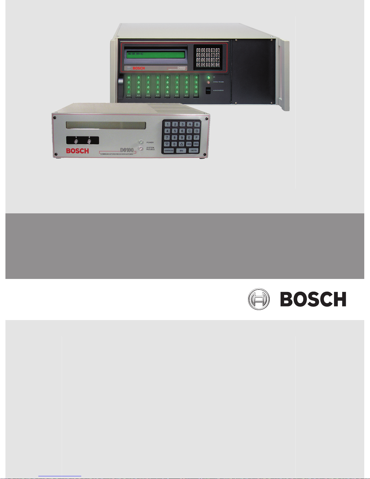
Conettix Communications Receiver/Gateway
D6600/D6100IPv6
en Installation and Operation Guide


Table of contents
1
Emergency Procedures 6
2
Introduction 7
2.1 About documentation 7
2.2 Bosch Security Systems, Inc. Product Manufacturing Dates 7
3
System overview 9
3.1 Parts List 10
4
Quick Installation 11
4.1 Setting the Time and Date 13
5
Card Functions and Locations 14
5.1 D6600 Front Panel 14
5.2 Line Cards and Modules 15
5.3 D6600 Rear View 16
5.3.1 D6600 Internal View 17
5.4 D6100IPv6 Front Panel 18
5.5 D6100IPv6 Rear View 18
6
D6600 Specific Cards 19
6.1 D6640/D6641 Line Cards and D6645 Line Terminator Cards 19
6.1.1 D6640/D6641 LED Descriptions 20
6.2 Card Installation 20
6.3 D6610 CPU Card and D6615 CPU Terminator Card 22
6.4 Card Removal and Replacement 23
7
Printer Specifications 24
8
Installation 25
8.1 Installation Check List 25
8.2 Rack Mount Instructions 26
8.3 Removing Power to the Receiver 26
9
Power 27
9.1 Power Supply Modules 27
9.2 Main Power 27
9.3 Standby Power 27
9.4 Connecting External Batteries 27
9.4.1 Minimum Standby Battery 28
9.4.2 Minimum Standby UPS Power 29
9.4.3 Estimated BTU Load 29
10
Input and Output Ports 30
10.1 Overview of Input and Output Ports 30
10.1.1 UPS Monitoring through CPU Programmable Input Ports 30
10.1.2 Automation Link Monitoring (COM3) through CPU Programmable Output Ports 32
11
D6600/D6100IPv6 Operation 33
11.1 Process Flow 33
11.1.1 Receiver Handshake and Kiss-Off 33
11.1.2 Message Verification 33
11.1.3 Handshake Tone Compatibility 33
11.1.4 Message is Received 33
11.1.5 How Call Groups Work 34
11.1.6 Buzzer Operation 34
11.1.7 Reporting Devices: Primary and Secondary 34
Conettix Communications Receiver/
Gateway
Table of Contents | en 3
Bosch Security Systems, Inc. Installation and Operation Guide 2012.11 | 08 | 4998122704

11.2 Normal Operation Mode 35
11.3 Operating in Manual Mode 35
11.4 Keypad Menu Operation 36
11.4.1 Log In 36
11.4.2 Using the Keypad 36
11.4.3 Event Buffer Display 36
11.4.4 Current System Trouble Display 36
11.4.5 Software Version Display 37
11.4.6 Keypad Functions 37
11.5 Busy Seconds (Line Busy) Reports 38
11.6 Two-Way Audio 39
11.6.1 Enhancements and Changes 40
11.6.2 Two-Way Auto Modes of Operation 40
12
Network Communications 42
12.1 Conettix D6600/D6100IPv6 Pre-installation Requirements 46
12.1.1 Setting Up the Conettix D6600/D6100IPv6 over an Ethernet Network 46
12.1.2 Host Computer for Conettix D6600/D6100IPv6 System Setup 46
12.2 Operation 46
12.2.1 Setting Up the Host Computer 46
12.2.2 Network Failover Solution (D6600 Only) 51
12.2.3 Conettix Datagram Type Differences 53
12.2.4 Networking and Encryption 54
12.3 Special Conettix D6600 Applications 56
12.4 D6100IPv6 Configuration Setup Instructions 57
12.4.1 Factory Default IP Address 57
12.4.2 Identifying the MAC Hardware Address 58
12.4.3 Obtaining an IP Address 58
12.4.4 Using the D6200 to configure the D6100IPv6 58
12.4.5 Configuring for Network Communication 63
12.5 D6100i Configuration Setup Instructions 64
12.5.1 Identifying the MAC Hardware Address 64
12.5.2 Obtaining an IP Address 64
12.5.3 Initial IP Address Assignment Using ARP.EXE 65
12.5.4 Using Telnet to Finish the Configuration 66
12.5.5 Configuration Using Telnet 67
12.5.6 Configuring for Network Communication 70
13
No Data Received Reports 72
13.1 No Data Received 72
13.2 Data Error 72
13.3 Wrong Data 72
14
Central Station Automation System 73
15
Central Station Tips 75
15.1 Back-up Receiver 75
15.2 Computer Interface 75
15.3 D6200 Programming Software 75
15.4 Telephone Lines 75
15.5 Proper Ground 75
15.6 Radio Frequency Interference 76
15.7 Test Communicator 76
4 en | Table of Contents
Conettix Communications Receiver/
Gateway
2012.11 | 08 | 4998122704 Installation and Operation Guide Bosch Security Systems, Inc.

16
Troubleshooting Guide 77
17
Specifications 80
18
Service Information 84
Conettix Communications Receiver/
Gateway
Table of Contents | en 5
Bosch Security Systems, Inc. Installation and Operation Guide 2012.11 | 08 | 4998122704
Emergency Procedures
i
Notice!
Throughout this document references to D6100IPv6 also apply to the D6100IPv6 unless other-
wise noted.
The Service Information, page 84 section of this guide contains a Service Information form.
Keep this form current and accessible to central station personnel at all times in case of
emergency.
If your D6600/D6100IPv6 becomes inoperable or experiences trouble receiving signals:
1. Notify your supervisor.
2. Refer to Troubleshooting Guide, page 77.
3. Contact Bosch Security Systems, Inc. at (800) 289-0096 for assistance if you have a
receiver spares package and need to replace a circuit card or module.
i
Notice!
The AC/DC Power Supply Module and DC/DC Power Supply Module for the D6600 are not
field serviceable. Contact Bosch Security Systems, Inc. for service.
Caution!
Disconnect power to the receiver before removing the CPU or CPU terminator card.
Before Calling
1. Have this guide nearby and opened to Troubleshooting Guide, page 77.
2. Have your spares package, the D6200 Programming Software, and the D6600/D6100IPv6
Program Entry Guide (P/N: 4998122702) nearby.
3. Know the location of the telephone line jacks for the receiver.
4. Know the telephone numbers to the receiver’s telephone line cards.
5. Know the exact nature of the problem you are experiencing such as reports received,
LEDs lit, or Operator Alert Buzzer sounded.
6. Have the service information form nearby (refer to Service Information, page 84).
1
6 en | Emergency Procedures
Conettix Communications Receiver/
Gateway
2012.11 | 08 | 4998122704 Installation and Operation Guide Bosch Security Systems, Inc.
Introduction
About documentation
Document Terminology
Action buttons for the D6600/D6100IPv6 are described using the following terminology:
D6600 D6100IPv6 Terminology
[M/E] [ENTER] Enter
[∆] [∆] Up (a level)
[∇] [∇] Down (a level)
[CAN] [CANCEL] Cancel
[] [ACKNOWLEDGE] Acknowledge
[F] [FUNCTION] Function
Copyright
This document is the intellectual property of Bosch Security Systems, Inc. and is protected by
copyright. All rights reserved.
Trademarks
All hardware and software product names used in this document are likely to be registered
trademarks and must be treated accordingly.
Conettix Documentation
Conettix DX4020 Installation Guide – F01U045288
Conettix D6600/D6100IPv6 Quick Start (this document) – 4998122701
Conettix D6600/D6100IPv6 Program Entry Guide – 4998122702
Conettix D6600/D6100IPv6 Computer Interface Manual – 4998122703
Conettix D6600/D6100IPv6 Release Notes – 4998122709
D6202 Operation and Installation Guide – 4998122713
Conettix D6201 Installation Instructions – 4998122717
C900TTL-E Installation Guide – 4998122718
DeviceInstaller Operation and Installation Guide – 4998138688
Conettix D6680 Installation Guide – 4998138732
Conettix ITS-D6686 Installation Guide – F01U078049
Conettix D6600 Card Insertion Installation Guide – 4998141059
Conettix D6200 Operation and Installation Guide – 4998154991
Conettix C900V2 Installation Guide – F01U003472
Ethernet Communication Module B420 Operation and Installation Guide – F01U215236
Ethernet Communication Module B426 Operation and Installation Guide – F01U266226
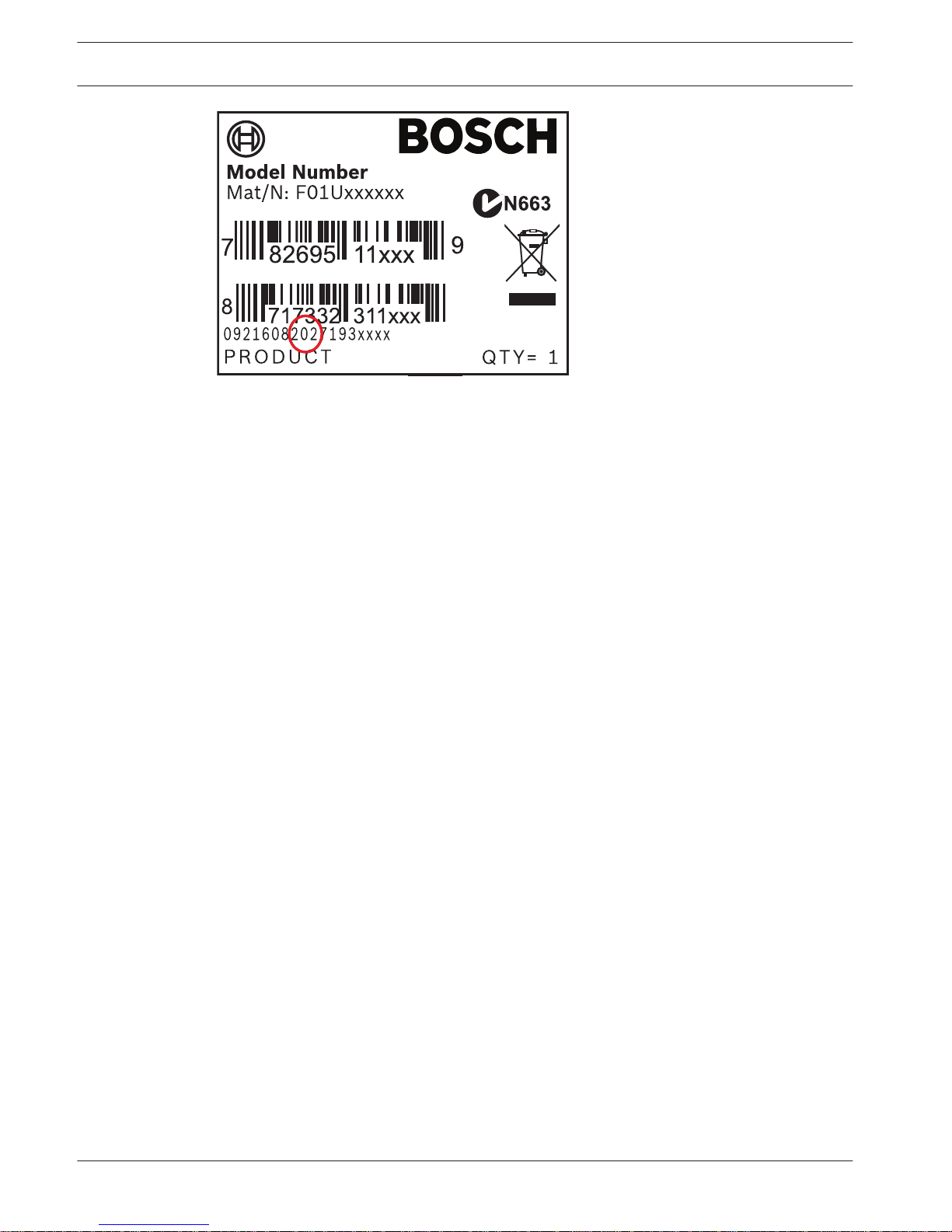
Bosch Security Systems, Inc. Product Manufacturing Dates
Use the serial number located on the product label and refer to the Bosch Security Systems,
Inc. web site at http://www.boschsecurity.com/datecodes.
The following image shows an example of a product label and highlights where to find the
manufacturing date within the serial number.
2
2.1
2.2
Conettix Communications Receiver/
Gateway
Introduction | en 7
Bosch Security Systems, Inc. Installation and Operation Guide 2012.11 | 08 | 4998122704
8 en | Introduction
Conettix Communications Receiver/
Gateway
2012.11 | 08 | 4998122704 Installation and Operation Guide Bosch Security Systems, Inc.
System overview
i
Notice!
The D6600/D6100IPv6 Installation and Operation Guide covers the general installation and op-
eration of the products.
Refer to the appropriate Installation Supplement included with your product for the specifics
of your particular installation.
Customers ordering a D6100IPv6-01 receive a Model D6100IPv6 Communications Receiver/
Gateway, and should refer to the UL864 & UL1610 Installation Supplement (P/N: F01U134241)
included with the product.
The Conettix D6600/D6100IPv6 Communications Receiver/Gateway offers several unique
features:
– Modular construction with plug-in circuit boards for quick, easy service
– Open-structure PC platform for future development
– Programmable formatting for receiving data from most major brands of digital
communicators
– Easy and inexpensive updating using modular cards (D6600 only)
– Convenient software downloads
– Superior digital signal processing to reduce noise and signal loss
– User interface module with LED indicators
– Front panel keypad
– Alphanumeric liquid crystal display (LCD The D6600 metal enclosure contains several
modular cards:
– Conettix D6610 Central Processing Unit (CPU) Card
– Conettix D6615 CPU Terminator Card
– Conettix D6640 or D6641 Telephone Line Card that supports four telephone line
interfaces
– Conettix D6645 Telephone Line Terminator Card
Up to seven additional telephone line cards along with seven additional line terminator cards
can be installed in the D6600 to expand the receiver’s capacity to 32 receiving lines.
D6600/D6100IPv6 Supported Communication Formats
Acron Super Fast ROBOFON*
Ademco Slow Scantronics Scancom*
Ademco Express Seriee FSK/DTMF*
Ademco High Speed Sescoa Super Speed
Ademco Contact ID SIA 8/20/300
CFSK Bell/V.21* SIA ADT*
FBI Superfast SIA V.21*
Franklin/Sescoa Silent Knight Fast
ITI* Silent Knight FSK
Radionics BFSK Standard Pulse Formats
Radionics Hex Sur-Gard DTMF
3
Conettix Communications Receiver/
Gateway
System overview | en 9
Bosch Security Systems, Inc. Installation and Operation Guide 2012.11 | 08 | 4998122704

Radionics Modem II Telim*
Bosch Modem4/ModemIIIa²/ModemIIe Veritech FSK
RB2000 (D6641 only)* VONK (D6641 only)*
* Not investigated by UL.
– Use a printer to permanently record date, time, group number or transmission format and
line number, account number, receiver number, and event by area, zone, and point. The
printer tape and the D6600/D6100IPv6 LCD display show other receiver status messages
such as software revision levels of the CPU Card.
– Program the D6600/D6100IPv6 using the front panel keypad or through the COM4 port
with the D6200 Programming Software package.
– The Conettix D6600/D6100IPv6 support data network communications including an
account database capacity of up to 3200 accounts with the optional Conettix D6201 IP
Security Key.
– The D6600/D6100IPv6 works with the following Bosch Security Systems, Inc. control
panels (referred to throughout this manual as “Bosch control panels”): D9412GV3/
D7412GV3/D7212GV3, D9412GV2/D7412GV2/D7212GV2, D9412G/D7412G/D7212G/
D9412/D7412/D7212, and D911.
Parts List
Conettix D6600 System Components
– One Conettix D6600 Communications Receiver/Gateway
– One AC power cord
– One Battery cable P6601
– I/O cable P6602
– Two rack mount brackets
– Four 8/32 phillips-head screws
– One CD-ROM D6200CD
The D6X00 README.TXT file on the CD lists the installation files contained on the CD.
Conettix D6100IPv6 System Components
– Conettix D6100IPv6 Communications Receiver/Gateway
– 18 VAC transformer
– Battery cable P6601
– I/O cable P6602
– CD-ROM D6200CD
The D6X00 README.TXT file on the CD lists the installation files contained on the CD.
3.1
10 en | System overview
Conettix Communications Receiver/
Gateway
2012.11 | 08 | 4998122704 Installation and Operation Guide Bosch Security Systems, Inc.

Quick Installation
D6600
1. Place the D6600 in a secure location.
2. Remove the tie wrap from the receiver door handle. Open the door and remove the
packaging foam from the front of the CPU Card.
3. Gently push the CPU and line cards into their slots until they connect securely.
4. Ensure that the D6600 power switch is in the OFF position.
5. Plug the AC power cord into the rear of the D6600.
6. Plug the other end into an unswitched 100 to 120 VAC (or 220 to 230 VAC), 50 to 60 Hz
line.
7. Refer to the figure AC Power and Telephone Connections, page 12. Plug the telephone
lines into the connectors on the first line terminator card.
8. If you need a network automation connection, skip this step and continue with the
remainder of the installation. For additional instructions on connecting automation
software to the network, refer to Network Communications, page 42. Refer to the figure
Automation PC and External Parallel Printer Connections, page 12. Connect the
automation computer (callout 1) to COM3 the center DB-9 connector on the CPU
terminator card, using a null-modem cable (callout 2).
9. Refer to the figure Automation PC and External Parallel Printer Connections, page 12.
Connect an external parallel printer, with the power off (callout 4), to the lower 25-pin
connector on the CPU terminator card (callout 5).
10. Turn the power switch on the D6600 to the ON position.
11. Press the UP button to increase display contract. Press the Down button to decrease
display contrast.
12. Press the Menu button to enter the menu.
13. On the Enter Password screen, type 6600 (default password).
14. Press the Enter button to enter the menu.
Use these keys to operate the D6600 menus:
Enter – Enter a menu level
Cancel– Return to the previous menu level
UP/Down arrow – Scroll through the menus
15. Set the Time and Date on the D6600 (refer to Setting the Time and Date, page 13).
16. The D6600 is ready to accept calls.
D6100IPv6
1. Place the D6100IPv6 in a secure location (such as a rack mount or desktop).
2. Refer to the figure AC Power and Telephone Connections, page 12. Plug telephone lines
into the connectors on the back of the D6100IPv6.
3. If you need a network automation connection, skip this step and continue with the
remainder of the installation. For additional instructions on connecting automation
software to the network, refer to Network Communications, page 42. Refer to the figure
Automation PC and External Parallel Printer Connections, page 12. Connect the
automation computer (callout 1) to COM3, the DB-9 connector using a null-modem cable
(callout 2).
4. Refer to the figure Automation PC and External Parallel Printer Connections, page 12.
Connect an external parallel printer (callout 4), with the power off, to the 25-pin
connector (callout 6).
5. Connect the transformer leads to the 18 VAC terminals and plug the other end into the
power source.
4
Conettix Communications Receiver/
Gateway
Quick Installation | en 11
Bosch Security Systems, Inc. Installation and Operation Guide 2012.11 | 08 | 4998122704
6. Press the Up to increase the display contrast. Press the Down arrow to decrease the
display contrast.
7. Press the Menu button to enter the menu.
8. On the Enter Password screen, type 6100 (default password).
9. Press the Menu button to enter the menu.
Use these keys to operate the D6100IPv6 menus:
Menu – Enter a menu level
Cancel – Return to the previous menu level
Up/Down arrow – Scroll through the menus
10. Set the Time and Date on the D6100IPv6 (refer to Setting the Time and Date, page 13).
11. The D6100IPv6 is ready to accept calls.
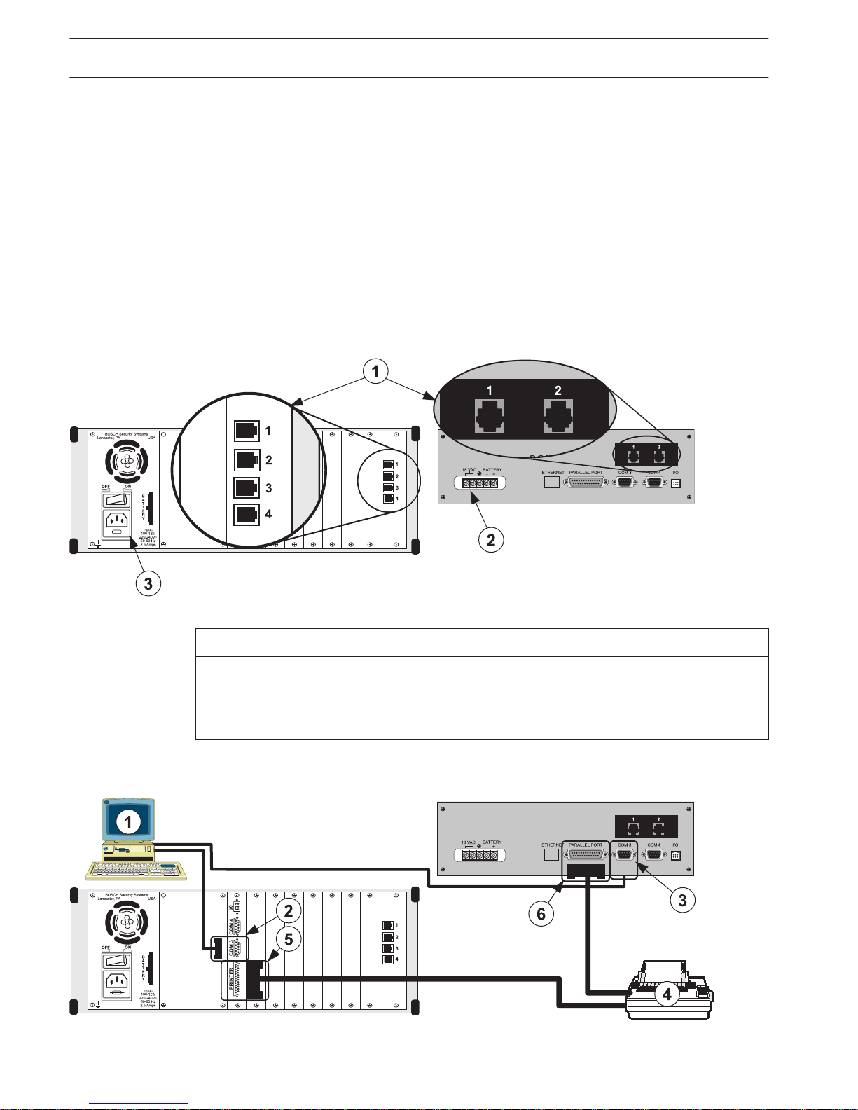
AC Power and Telephone Connections
D6100IPv6D6600
Figure 4.1: AC Power and Telephone Connections
Callout ᅳ Description
1 ᅳ Telephone connection
2 ᅳ AC power terminals
3 ᅳ AC power connector
Automation PC and External Parallel Printer Connections
D6100IPv6
D6600
Figure 4.2: Automation PC and External Parallel Printer Connections
12 en | Quick Installation
Conettix Communications Receiver/
Gateway
2012.11 | 08 | 4998122704 Installation and Operation Guide Bosch Security Systems, Inc.
Callout ᅳ Description
1 ᅳ Automation PC
2 ᅳ COM3 9-pin port (D6600)
3 ᅳ COM3 9-pin port (D6100IPv6)
4 ᅳ Parallel printer
5 ᅳ 25-pin parallel port (D6600)
6 ᅳ 25-pin parallel port (D6100IPv6)
Setting the Time and Date
i
Notice!
The Time and Date display format is determined by the programming for Menu Item 2.2.3 Set
Country.
Time Setup D6600/D6100IPv6
1. Press the Enter button to go to the log in screen.
2. Enter the password (6600 – default password).
3. Press the Enter button to go to the 1 Event Database
4. Press the Down button to go to 2 CPU Configuration.
5. Press the Enter button to go to 2.2 Global.
6. Press the Enter button to go to 2.2.1 Time Setup.
7. Press the Enter button to go to Set Time.
8. Enter the current time.
9. Press the Enter button to go to 2.2.1 Time Setup/New Time Set…
10. Press the Cancel button to return to the previous level.
Date Setup D6600/D6100IPv6
1. Press the Enter button to go to the log in screen.
2. Enter the password (6600 – default password).
3. Press the Enter button to go to the 1 Event Database.
4. Press the Down button to go to 2 CPU Configuration.
5. Press the Enter button to go to 2.2 Global.
6. Press the Enter button to go to 2.2.2 Date Setup.
7. Press the Enter button to go to Set Date.
8. Enter the current time.
9. Press the Enter button to go to 2.2.2 Date Setup/Current Setting…
10. Press the Cancel button to return to the previous level.
4.1
Conettix Communications Receiver/
Gateway
Quick Installation | en 13
Bosch Security Systems, Inc. Installation and Operation Guide 2012.11 | 08 | 4998122704
Card Functions and Locations
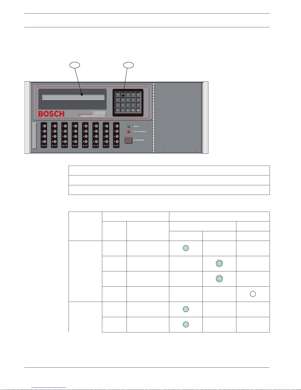
D6600 Front Panel
1 2
Figure 5.1: D6600 Communications Receiver/Gateway (Front View)
Callout ᅳ Description
1 ᅳ LCD – shows up to 80 characters of information (two lines of up to 40 characters each).
2 ᅳ Keypad – the D6600 has a 20-button keypad.
The table below shows and defines the D6600/D6100IPv6 Power LEDs.
2.234
Battery
Supervision
Present Power LED Status
A
C
Battery Green Clear
Solid Blinking
On X X
X
X
Off X X
X
5
5.1
14 en | Card Functions and Locations
Conettix Communications Receiver/
Gateway
2012.11 | 08 | 4998122704 Installation and Operation Guide Bosch Security Systems, Inc.
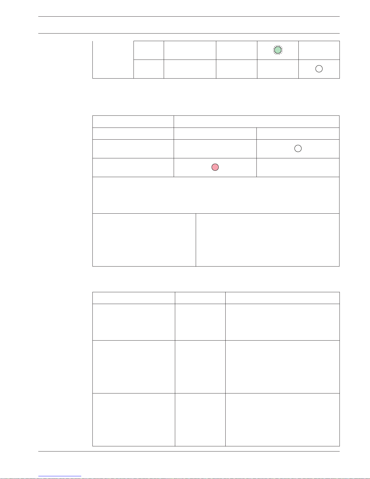
X
Table 5.1: Power LED Indications
The figure below shows and defines the D6600/D6100IPv6 System Trouble LEDs.
System Trouble LED Status
Solid Red or Yellow Clear
No System Trouble
Any System Trouble*
* Refer to Appendix B: D6600/D6100IPv6 Internal Messages in the D6600/D6100IPv6 Computer
Interface Manual (P/N: 4998122703). The following items cause system trouble. The items
indicated by ** can be enabled or disabled. If they are disabled, they will not cause a system
trouble condition.
Battery Missing**
UPS AC Fail**
Battery Bad**
UPS Battery Low**
AC Fail
System Temperature High
External Printing Error**
Line Fault**
COM# Error**
Line Card Trouble**
COM3 Trouble**
Table 5.2: System Trouble LED
Line Cards and Modules
Name Model Description
Telephone line card D6640 Legacy Card:
Up to eight line cards can be installed in
one D6600 Receiver, for up to 32
telephone line connections.
Telephone line card D6641 Functions like the D6640. Includes
improved Public Switched Telephone
Network (PSTN) processing, additional
memory for future enhancements such as
VoIP Compensation, and single firmware
upgrade package.
CPU card D6610 The D6600 uses one CPU card. The CPU
card takes the incoming information from
the line card and routes the information
to an automation port, the LCD on the
front of the receiver, and an external
printer.
5.2
Conettix Communications Receiver/
Gateway
Card Functions and Locations | en 15
Bosch Security Systems, Inc. Installation and Operation Guide 2012.11 | 08 | 4998122704
Power supply modules D6630 and
D6631
The power supply modules regulate the
power used by the D6600. These are not
field serviceable.
Telephone line terminator
card
D6645 Located behind the line card, the
telephone line terminator card isolates
and protects the line card against outside
voltage surges that might come over the
telephone line. Each line card must have a
line terminator card.
CPU terminator card D6615 Located behind the CPU card, the CPU
terminator card provides the D6600 with
two serial ports (COM3 and COM4), a
parallel port (parallel printer), and a
general I/O port (I/O). The serial ports
can be used for computer automation, PC
connection for programming, or a network
connection with a Network Ethernet
Module (see specific installation guide
supplied with your product).
Table 5.3: D6600 Line Cards and Modules
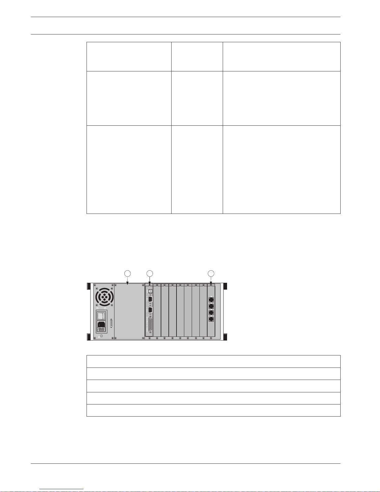
D6600 Rear View
The D6600 has input and output pin connector sockets for up to eight line cards, network
option (if installed), and one CPU card. It also has slots for connecting these cards to their
corresponding terminator cards.
1
2
3
4
Bosch Security Systems
Fairport, NY USA
Input:
100 - 120/
220 - 240V~
50 - 60 Hz
2.5 Amps
B
A
T
T
E
R
Y
1 2 3
Figure 5.2: D6600 Communications Receiver/Gateway (Rear View)
Callout ᅳ Description
1 ᅳ Blank plate and location of optional Conettix D6672 COM1 Expansion Kit
2 ᅳ Conettix D6615 CPU Terminator Card
3 ᅳ Card slot covers
4 ᅳ Conettix D6645 Line Terminator Card
5.3
16 en | Card Functions and Locations
Conettix Communications Receiver/
Gateway
2012.11 | 08 | 4998122704 Installation and Operation Guide Bosch Security Systems, Inc.
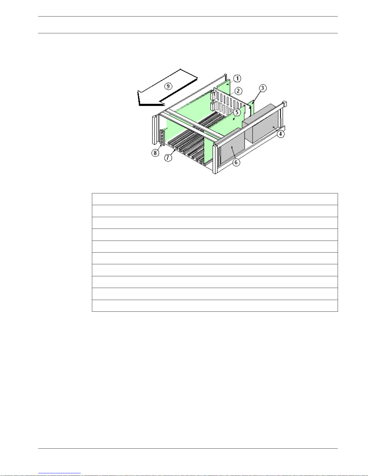
D6600 Internal View
Figure 5.3: Receiver Card Placement
Callout ᅳ Description
1 ᅳ Conettix D6645 Telephone Line Terminator Card
2 ᅳ Backplane
3 ᅳ Conettix D6615 CPU Terminator Card
4 ᅳ D6630 AC/DC Power Supply (not serviceable)
5 ᅳ Conettix D6610 CPU Card
6 ᅳ D6631 AC/DC Power Supply (not serviceable)
7 ᅳ Card guides
8 ᅳ Conettix D6640/D6641 Telephone Line Card
9 ᅳ Direction of receiver front
5.3.1
Conettix Communications Receiver/
Gateway
Card Functions and Locations | en 17
Bosch Security Systems, Inc. Installation and Operation Guide 2012.11 | 08 | 4998122704
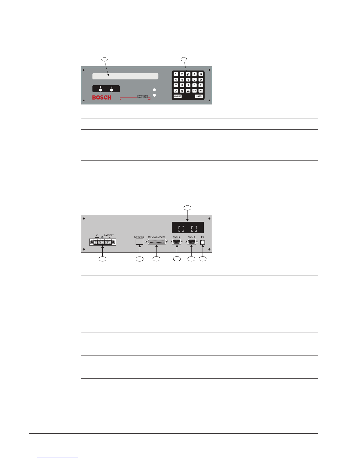
D6100IPv6 Front Panel
COMMUNICATIONS RECEIVER/GATEWAY
POWER
SYSTEM
TROUBLE
1
2
Figure 5.4: D6100IPv6 Communications Receiver/Gateway (Front View)
Callout ᅳ Description
1 ᅳ Liquid crystal display (LCD) - Displays up to 80 characters of information (two lines of
up to 40 characters each).
2 ᅳ 23-button keypad.
D6100IPv6 Rear View
Line Cards and Modules
The D6100IPv6 does not use the same line cards and modules as the D6600. These functions
are built in.
1 2
1
7
6
5 4
3
2
Figure 5.5: D6100IPv6 Communications Receiver/Gateway (Rear View)
Callout ᅳ Description
1 ᅳ Telephone line connections
2 ᅳ Input/output ports
3 ᅳ COM RS-232 port
4 ᅳ COM3 auxiliary RS-232 port
5 ᅳ Parallel port connection
6 ᅳ Ethernet port (D6100IPv6 only)
7 ᅳ USB port
8 ᅳ Power connection terminal block
5.4
5.5
18 en | Card Functions and Locations
Conettix Communications Receiver/
Gateway
2012.11 | 08 | 4998122704 Installation and Operation Guide Bosch Security Systems, Inc.
D6600 Specific Cards
D6640/D6641 Line Cards and D6645 Line Terminator Cards
i
Notice!
Starting with D6200 v2.0 the D6640 Line Card is no longer be supported. Information about
the D6640 is provided in this section for legacy support only.
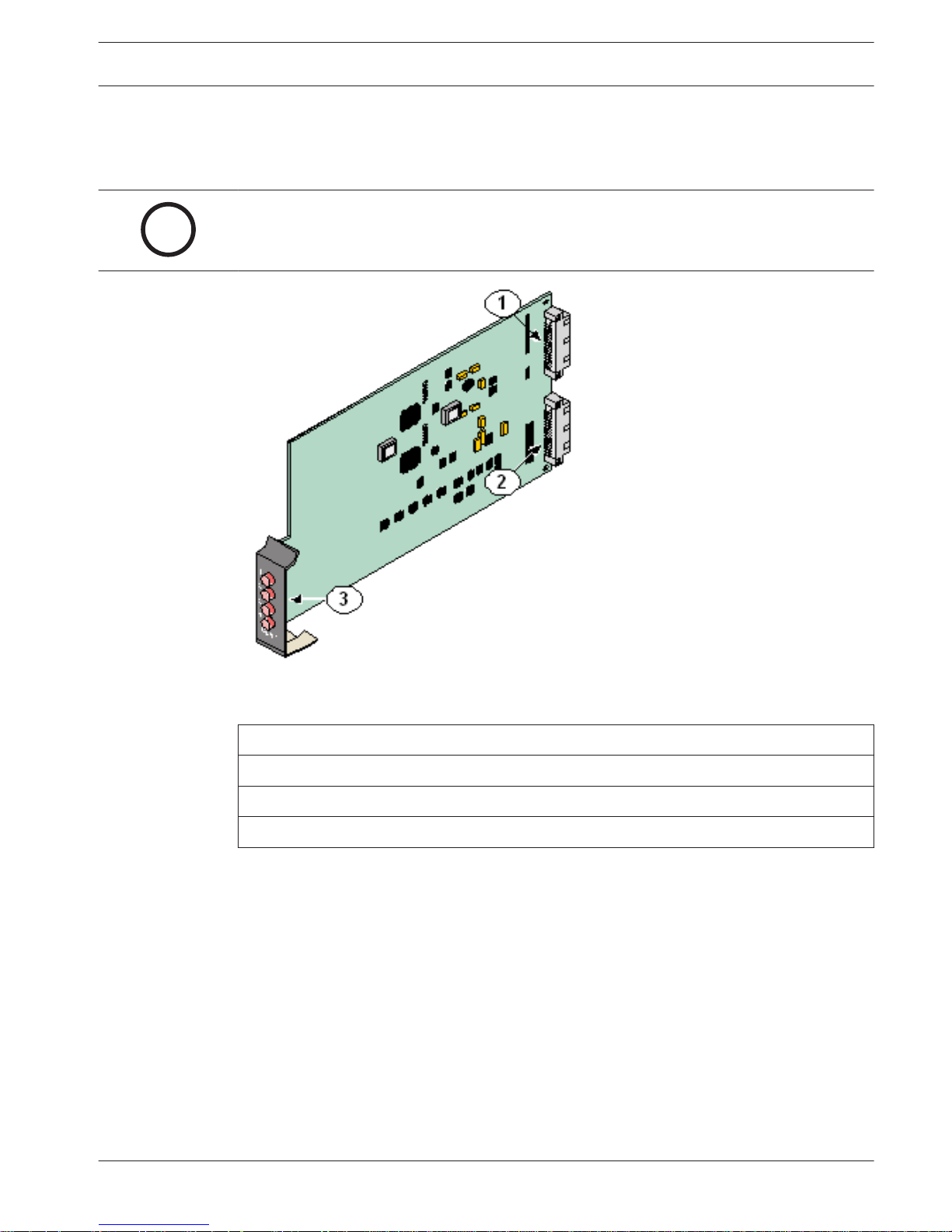
Figure 6.1: D6640/D6641 Line Card
Callout ᅳ Description
1 ᅳ 48-pin connection to D6645 Line Termination Card
2 ᅳ 40-pin connection to D6600 Back Plate
3 ᅳ LEDs (Refer to D6640/D6641 LED Descriptions, page 20)
6
6.1
Conettix Communications Receiver/
Gateway
D6600 Specific Cards | en 19
Bosch Security Systems, Inc. Installation and Operation Guide 2012.11 | 08 | 4998122704
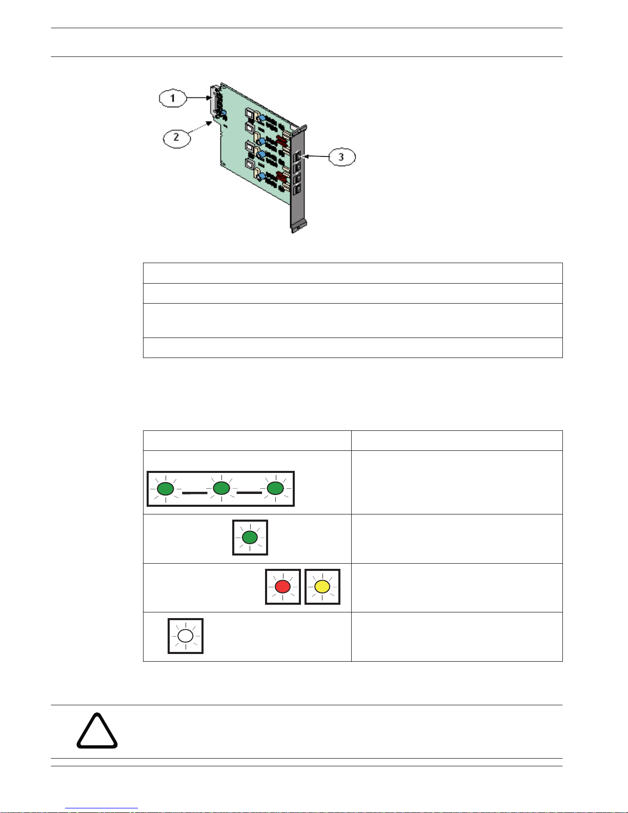
Figure 6.2: D6645 Line Terminator Card
Callout ᅳ Description
1 ᅳ 48-pin connection to D6640/D6641 Line Card.
2 ᅳ Alignment Guide - Stabilizes the connection and acts as a guide for connecting the
terminator card to the line card.
3 ᅳ Telco Line Jacks - Standard telephone lines connect to the RJ11C jacks.
D6640/D6641 LED Descriptions
Each LED represents a line. For example, LED 1 is for line 1. The LED is active until the system
acknowledges the entire transmission and the telephone line is ready to receive signals. The
following table describes LED patterns and colors, and their indications.
Flash Pattern (Color) Function
Flashes (green) An incoming call is ringing.
ON Steady (green)
The receiver is online.
ON Steady (red or yellow)
The line card detects a line fault condition.
OFF
The line card is ready to receive signals, or is
disabled.
Table 6.1: LED Descriptions
Card Installation
!
Warning!
Discharge static electricity from your body by touching the receiver’s internal frame (unpain-
ted section) before handling any circuit card.
6.1.1
6.2
20 en | D6600 Specific Cards
Conettix Communications Receiver/
Gateway
2012.11 | 08 | 4998122704 Installation and Operation Guide Bosch Security Systems, Inc.
Installing Terminator Cards
Refer to D6640/D6641 Line Cards and D6645 Line Terminator Cards, page 19 when performing
the following steps:
1. Remove the two bracket screws that secure the terminator card (or card slot cover, if this
is a new terminator card installation) to the back of the D6600 chassis.
2. If you are removing an existing terminator card, open the display door on the front of the
D6600 and pull the line card slightly out, then re-insert. This will push the existing
terminator card out the back of the D6600 chassis.
3. Remove the existing terminator card. Insert the new terminator card in the same slot by
aligning the top and bottom of the terminator card with the card guides in the D6600
chassis.
4. Slide the card into the D6600 chassis, wiggling the card as you push until the card is flush
with the back of the chassis.
5. Secure the bracket screws at the top and bottom of the terminator card. Ensure that the
screws are tight.
6. Repeat this process for all additional terminator cards.
7. Connect appropriate telephone line cords to the telephone line jack on the terminator
cards.
8. Continue to Installing Line Cards, page 21.
i
Notice!
Even if you are replacing an existing terminator card, you must proceed to Installing Line
Cards.
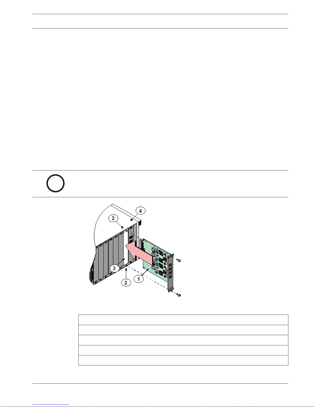
Figure 6.3: Removing and Installing the Terminator Card
Callout ᅳ Description
1 ᅳ Terminator Card (D6645 shown)
2 ᅳ Bracket screws (top and bottom)
3 ᅳ Empty slot
4 ᅳ D6600 chassis
Installing Line Cards
1. Install the terminator card(s) (Refer to Installing Terminator Cards, page 21).
Conettix Communications Receiver/
Gateway
D6600 Specific Cards | en 21
Bosch Security Systems, Inc. Installation and Operation Guide 2012.11 | 08 | 4998122704
2. Open the display door on the D6600. One telephone line card is installed in the D6600
when the unit is shipped from the factory.
3. Insert the new line card into the slot by aligning the top and bottom of the line card with
the card guides in the D6600 chassis. Firmly push the card to make sure it is fully
connected.
4. If you are installing a new telephone line card, remove the appropriate snap-in covers
from the front of the panel.
5. Close the front panel.
6. Program the line card if necessary.
When the line card is initialized (as indicated by a printer report), the settings in the line
card programming section automatically load into the card.
7. Connect communication lines to the line card.
D6640/D6641 Telephone Line Monitoring
Each line on the line card continuously monitors the telephone line voltage whether on-hook
or off-hook. If the voltage on a line falls below 1.8 VDC a Line Trouble indication is generated
and when it rises above 2.5 VDC it generates a restoral for this line.
D6610 CPU Card and D6615 CPU Terminator Card
The CPU card connects to the user interface on the front of the D6600 using a 50-pin ribbon
cable socket.
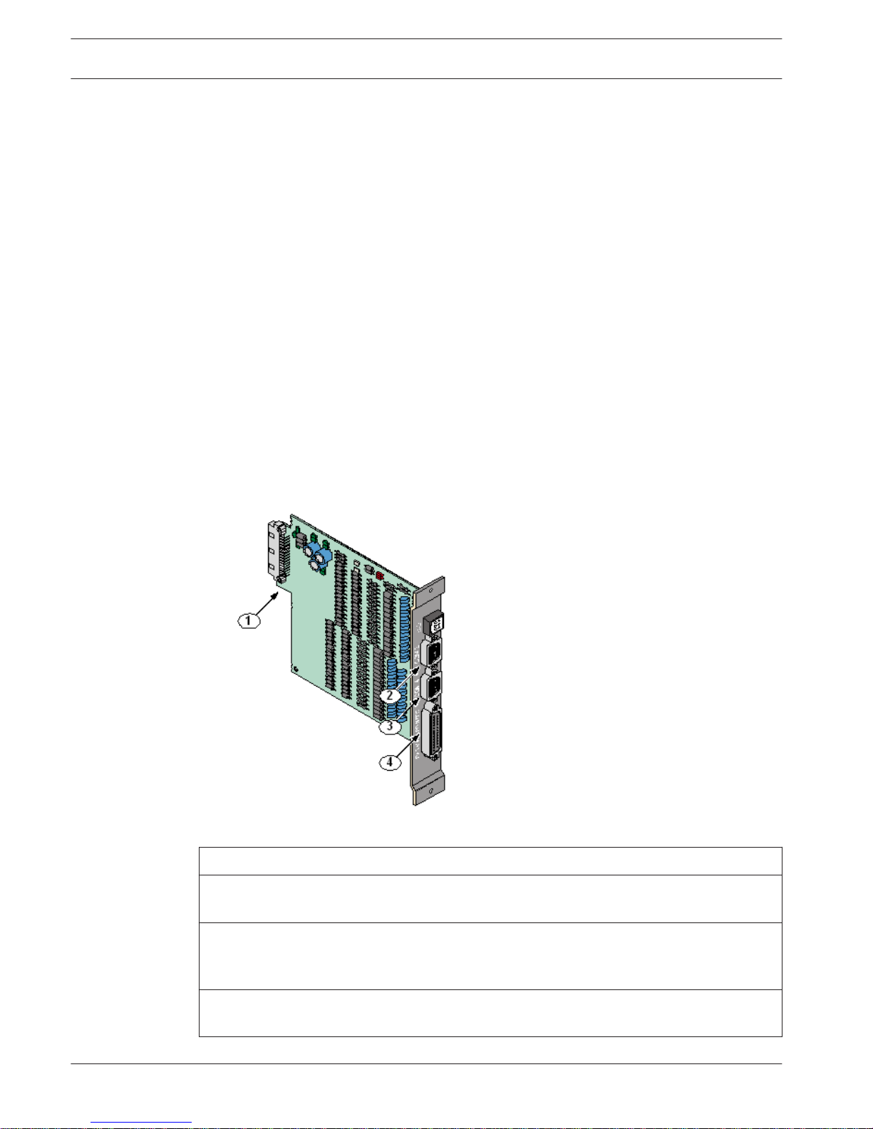
Figure 6.4: D6615 CPU Terminator Card
Callout ᅳ Description
1 ᅳ Alignment Guide - Stabilizes the connection and acts as a guide for connecting the
terminator card to the CPU card.
2 ᅳ COM3 Automation Computer Port - An auxiliary RS-232 port for connecting to a
computer terminal or an automation computer. For SIA/6500 Mode Automation Format
reporting, use a null-modem cable to connect to a computer.
3 ᅳ COM4 RS-232 Port - Connection to a computer running the D6200 programming
software.*
6.3
22 en | D6600 Specific Cards
Conettix Communications Receiver/
Gateway
2012.11 | 08 | 4998122704 Installation and Operation Guide Bosch Security Systems, Inc.
4 ᅳ Parallel Printer Port.
* Use a null-modem cable to connect directly to the computer. You can also connect this port
to a Network Ethernet Module for communicating over a network.
Card Removal and Replacement
!
Warning!
Remove power to the D6600 before removing, replacing, or installing the CPU card (D6610)
or CPU terminator card (D6615).
Removing the CPU Card
1. Remove power to the receiver (refer to Removing Power to the Receiver, page 26).
2. Carefully grasp the plastic grip on the CPU card. Slide it 2 in to 3 in (50 mm to 75 mm)
out of the enclosure.
3. Unplug the 50-pin ribbon cable connecting the user interface card to the CPU card. Be
careful not to bend the board when disconnecting this cable. Grasp the plastic plug
connected to the CPU board at the end of the cable and gently pull it away from the
circuit board.
4. Pull the CPU card straight out of the card guide.
Replacing the CPU Card
1. Remove power to the receiver (refer to Removing Power to the Receiver, page 26).
2. Remove the defective CPU card from the enclosure.
3. Align the top and bottom of the CPU card with the card guides. Slide the card into the
enclosure, leaving 2 to 3 in (50 mm to 75 mm) out to connect the ribbon cable.
4. Connect the ribbon cable to the CPU card. Orient the cable so the red stripe is up, and
slide the card the remaining distance into the enclosure.
5. Restore power to the receiver.
6.4
Conettix Communications Receiver/
Gateway
D6600 Specific Cards | en 23
Bosch Security Systems, Inc. Installation and Operation Guide 2012.11 | 08 | 4998122704

Printer Specifications
i
Notice!
Refer to the appropriate Installation Supplement included with your product for the specifics
of your particular installation.
Use the DB25 port on the back of the D6600/D6100IPv6 rear panel to connect to a standard
parallel text printer.
7
24 en | Printer Specifications
Conettix Communications Receiver/
Gateway
2012.11 | 08 | 4998122704 Installation and Operation Guide Bosch Security Systems, Inc.
Installation
i
Notice!
Refer to the appropriate Installation Supplement included with your product for the specifics
of your particular installation.
Installation Check List
Check each receiver card to see that it is correctly positioned in the card guides at the
top and bottom of the enclosure. Also confirm that connections did not loosen during
shipment (D6600 only).
Check each receiver card to see that it is correctly positioned in the card guides at the
top and bottom of the enclosure. Also confirm that connections did not loosen during
shipment (D6600 only).
Ensure that the earth ground is connected and grounded through the AC inlet.
If you are installing additional line cards, install the terminator cards now (D6600 only).
After installing additional line terminator cards, install the line cards (refer to Card
Installation, page 20).
Install the line terminator card(s) from your spares package(s). If there is a malfunction,
you can quickly switch over to the replacement card (refer to Card Installation, page 20).
i
Notice!
You can install spare line terminator cards. Do not install spare line cards.
Connect four or six conductor telephone cord(s) to the RJ11C jack(s) of the desired
telephone line(s). Plug the other end of the modular telephone cord(s) into the telephone jack
on the appropriate line terminator card(s).
Connect the supplied AC transformer wiring leads to the AC terminals on the rear of the
D6100IPv6.
Plug the AC cord (D6600 only) into a correctly wired 120 VAC, 60 Hz or 220 VAC, 50 Hz
outlet (standard AC outlet).
i
Notice!
Maintain a 6.5 mm (0.25 in) gap, or greater, between power limited and non-power limited
circuit wiring.
Plug the AC transformer into the correctly wired wall receptacle that matches the voltage
of the transformer.
8
8.1
Conettix Communications Receiver/
Gateway
Installation | en 25
Bosch Security Systems, Inc. Installation and Operation Guide 2012.11 | 08 | 4998122704
i
Notice!
Ensure that a switch does not control the outlet.
Turn the D6600 power switch on. The D6100IPv6 starts as soon as you plug in the AC
Transformer.
Set the calendar and clock to the correct date and time and program the necessary
options.
Ensure that the communication formats are correct by having communicators send test
reports to each line connected to the receiver.
Rack Mount Instructions
Refer to the specific installation guide supplied with your product.
Removing Power to the Receiver
1. Remove the battery power connection.
2. Turn off the AC power on the D6600 or unplug the D6100IPv6 AC transformer.
3. Unplug the AC cord from the outlet.
!
Warning!
Do not try to restart the D6600/D6100IPv6 with a fully discharged battery. Reconnect after
you apply power. To prevent deep battery discharge, use a D135A Low Battery Cutoff Module.
Refer to the D135A Installation Guide (P/N: 74-06499-000) for more information.
i
Notice!
If programmable Output 1 or 2 is activated by automation failure, you cannot clear Output 1
or 2 by pressing the Acknowledge key.
8.2
8.3
26 en | Installation
Conettix Communications Receiver/
Gateway
2012.11 | 08 | 4998122704 Installation and Operation Guide Bosch Security Systems, Inc.
Power
Power Supply Modules
Main Power
D6600 Power Input
AC Nominal Operating Range 120 V or 230 V
AC maximum Operating Range 100 VAC to 120 VAC, 220 VAC to 240 VAC, 50–60 Hz
2.5 A maximum
Power Cord IEC 60320 C13 type
Replaceable Fuse 2.5A F250V Fast blow 5x20mm
D6100IPv6 Power Input
AC Nominal Operating Range
18VAC (Refer to the specific Installation Supplement
supplied with your product for your application for
supplied transformer specifics)
Standby Power
i
Notice!
Refer to the appropriate Installation Supplement included with your product for the specifics
of your particular installation.
During a loss of AC power, the receiver automatically switches to standby power. External
batteries or an uninterruptible power supply (UPS) provides standby power. As long as there
is adequate standby power, the receiver’s operation is not interrupted, even if the power loss
occurs during signal processing. When power supervision is enabled and a loss of AC power
occurs, the primary reporting devices (such as printers and computers) show AC FAIL and the
D6600/D6100IPv6 power indicator starts blinking. When AC power restores, the power
indicator stops blinking and reporting devices show AC RESTORE.
Connecting External Batteries
i
Notice!
Do not connect an external battery charger to the D6600/D610IPv6 or its battery. There is a
risk of explosion if the battery is replaced by an incorrect type. Dispose of used batteries ac-
cording to the instructions.
Use the terminal on the rear panel to connect an external DC power source. During AC power
outages, the external DC source supplies power to the receiver. Use a 12 VDC, 7 to 18 Ah
lead-acid battery for external backup power.
Battery Voltage Display during AC power
outage
Display if no battery when
AC power is restored
Above 11.5 V Battery OK
9
9.1
9.2
9.3
9.4
Conettix Communications Receiver/
Gateway
Power | en 27
Bosch Security Systems, Inc. Installation and Operation Guide 2012.11 | 08 | 4998122704
 Loading...