

Bosch D6100i Installation And Operation Manual
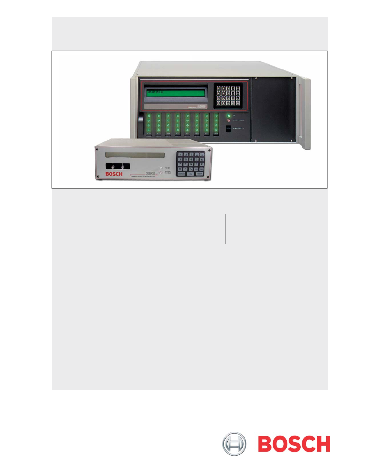
Conettix D6600/D6100i
Installation and Operation Guide
EN
Communications
Receiver/Gateway

Conettix D6600/D6100i | Installation and Operation Guide | Trademarks
Trademarks
Microsoft®, Windows®, Windows NT® are either
registered trademarks or trademarks of Microsoft
Corporation in the United States and/or other
countries.
Ademco
®
is a registered trademark of Alarm Device
Manufacturing Corporation.
2 Bosch Security Systems, Inc. | 8/07| 4998122704-02

Conettix D6600/D6100i | Installation and Operation Guide | Contents
.
Contents
1.0 Introduction .................................................5
2.0 Emergency Procedures...................................6
3.0 Card Functions and Locations ......................6
3.1 D6600 ..................................................................6
3.1.1 Front Panel..........................................................6
3.1.2 Line Cards and Modules...................................7
3.1.3 Rear View ...........................................................8
3.1.4 Internal View......................................................8
3.2 D6100i.................................................................9
3.2.1 Front Panel..........................................................9
3.2.2 Line Cards and Modules...................................9
3.2.3 Back Plate............................................................9
4.0 D6600 Specific Cards ......................................9
4.1 D6640/D6641 Line Cards and D6645 Line
Terminator Card ................................................9
4.1.1 D6640/D6641 LED Descriptions ...................10
4.1.2 Card Installation...............................................10
4.1.3 D6640/D6641Telephone Line Monitoring
Voltage ..............................................................11
4.2 D6610 CPU Card and D6615 CPU
Terminator Card ..............................................12
4.2.1 D6610 CPU Card Connection........................12
4.2.2 D6615 CPU Terminator Card........................12
4.2.3 Card Removal and Replacement ...................12
5.0 Power Supply Modules (D6600 Only) .......12
6.0 Printer Specifications....................................12
7.0 Installation ...............................................13
7.1 All Installations.................................................13
7.2 UL Installations ................................................13
7.3 Burglar Alarm Applications ............................13
7.4 Fire Alarm Applications ..................................13
7.5 Installation Check List.....................................13
7.6 Rack Mount Instructions.................................14
7.7 Removing Power to the Receiver...................14
8.0 Standby Power ...............................................14
8.1 Connecting External Batteries ........................14
8.1.1 Minimum Standby Battery..............................15
8.1.2 Minimum Standby UPS Power.......................15
9.0 Input and Output Ports.................................15
9.1 UPS Monitoring through CPU
Programmable Input Ports..............................16
9.1.1 Input Default Connection Configuration.......16
9.1.2 Input Reverse Connection Configuration .....16
9.2 Automation Link Monitoring (COM3)
through CPU Programmable Output Ports ...16
10.0 D6600/D6100i Operation.................................. 17
10.1 Process Flow..................................................... 17
10.1.1 Receiver Handshake and Kiss-Off................. 17
10.1.2 Message Verification ....................................... 17
10.1.3 Handshake Tone Compatibility..................... 17
10.1.4 Message is Received........................................ 17
10.1.5 How Call Groups Work.................................. 17
10.1.6 Buzzer Operation............................................. 18
10.1.7 Reporting Devices: Primary and Secondary. 18
10.2 Normal Operation Mode................................ 18
10.3 Operating in Manual Mode............................ 19
10.4 Keypad Menu Operation................................ 19
10.4.1 Log In................................................................ 19
10.4.2 Using the Keypad ............................................ 19
10.4.3 Event Buffer Display ....................................... 20
10.4.4 Current System Trouble Display ................... 20
10.4.5 Software Version Display................................20
10.4.6 Keypad Functions............................................ 20
10.4.7 Skip Current Automation Event .................... 21
10.4.8 Line Test........................................................... 21
10.4.9 Clear Pending Events...................................... 22
10.5 Busy Seconds (Line Busy) Reports................. 22
10.6 Two-Way Audio .............................................. 23
10.6.1 Enhancements and Changes........................... 23
10.6.2 Two-Way Audio Modes of Operation...........24
11.0 Network Communications........................... 25
12.0 No Data Received Reports.......................... 26
12.1 Description ....................................................... 26
12.2 No Data Received............................................ 26
12.3 Data Error......................................................... 26
12.4 Wrong Data...................................................... 26
13.0 Using the Central Station Automation
System with the Receiver ............................ 27
14.0 Central Station Tips...................................... 28
14.1 Back-up Receiver............................................. 28
14.2 Computer Interface ......................................... 28
14.3 D6200 Programming Software....................... 28
14.4 Telephone Lines ..............................................28
14.4.1 Emergency Ringers.......................................... 28
14.4.2 Rotary Lines..................................................... 28
14.5 Proper Ground................................................. 29
14.6 Radio Frequency Interference........................ 29
14.7 Test Communicator......................................... 29
15.0 Troubleshooting Guide................................ 30
16.0 Specifications ............................................... 33
Bosch Security Systems, Inc. | 8/07| 4998122704-02 3

Conettix D6600/D6100i | Installation and Operation Guide | Contents
17.0
Service Information ......................................35
Tables
Table 1: D6600/D6100i Supported
Figures
Figure 1: D6600 Communications
Receiver/Gateway (Front View)................6
Figure 2: D6600 Communications
Receiver/Gateway (Rear View)................. 8
Figure 3: Receiver Card Placement...........................8
Figure 4: D6100i Communications Receiver/
Gateway (Front View).................................9
Figure 5: D6100i Communications Receiver/
Gateway (Rear View)..................................9
Figure 6: D6640/D6641 Line Card ...........................9
Figure 7: D6645 Line Terminator Card.................... 9
Figure 8: D6640/D6641 LED Descriptions ............10
Figure 9: Removing and Installing Terminator
Card............................................................11
Figure 10: D6615 CPU Terminator Card.................12
Figure 11: Location of D6100i Battery Terminals
and D6600 Battery Connector.................13
Figure 12: D6600 Back Panel Showing
Input/Output Ports ...................................15
Figure 13: D6100i Back Panel Showing
Input/Output Ports ...................................15
Figure 14: Input Wiring for Reverse
Configuration.............................................16
Figure 15: Conettix Network System Connection
Diagram - C900TTL-E/C900V2
and Any Control Panel.............................25
Figure 16: Conettix Network System Connection
Diagram - D9133TTL-E/DX4020 and
Bosch Control Panels................................26
Figure 17: NO DATA RECEIVED Message...........26
Figure 18: Receiver System – Direct Connect .........27
Figure 19: Receiver System – Standard/Network
Automation................................................28
Table 2: Power LED Indications.............................. 6
Table 3: System Trouble LED.................................. 7
Table 4: D6600 Line Cards and Modules............... 7
Table 5: Battery Voltage Display ........................... 14
Table 6: Calculating Standby Current for the
Table 7: Standby Current for the D6100 ..............15
Table 8: Minimum Standby Battery Chart ...........15
Table 9: Terminator Card Configuration.............. 16
Table 10: Communication Links Test Outputs.......20
Table 11: Hardware Troubleshooting Guide.......... 30
Table 12: D6600/D6100i Specifications.................. 33
Communication Formats ........................... 5
D6600......................................................... 15
4 Bosch Security Systems, Inc. | 8/07| 4998122704-02
Conettix D6600/D6100i | Installation and Operation Guide | 1.0 Introduction
.
1.0 Introduction
The Conettix D6600/D6100i Communications
Receiver/Gateway offers several unique features:
• Modular construction with plug-in circuit boards
for quick, easy service
• Open structure PC platform for future
development
• Programmable formatting for receiving data from
most major brands of digital communicators
• Easy and inexpensive updating using modular
cards (D6600 only)
• Convenient software downloads
• Superior digital signal processing to reduce noise
and signal loss
• User interface module with LED indicators
• Front panel keypad
• Alphanumeric liquid crystal display (LCD)
The D6600 metal enclosure contains several modular
cards:
• Conettix D6610 Central Processing Unit (CPU)
Card
• Connetix D6615 CPU Terminator Card
• Conettix D6640 or D6641 Telephone Line Card
that supports four telephone line interfaces
• Connetix D6645 Telephone Line Terminator Card
Up to seven additional telephone line cards along with
seven additional line terminator cards can be installed
in the D6600 to expand the receiver’s capacity to 32
receiving lines.
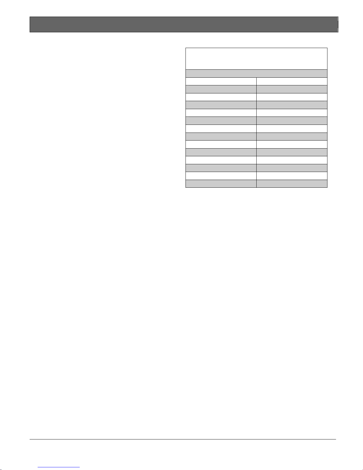
Table 1: D6600/D6100i Supported
Communication Formats
Acron Super Fast ROBOFON*
Ademco® Slow Scantronics Scancom*
Ademco Express Seriee FSK/DTMF*
Ademco High Speed Sescoa Super Speed
Ademco Contact ID SIA 8/20/300
CFSK Bell/V.21* SIA ADT*
FBI Superfast SIA V.21*
Franklin/Sescoa Silent Knight Fast
ITI* Silent Knight FSK
Radionics BFSK Standard Pulse Formats
Radionics Hex Sur-Gard DTMF
Radionics Modem II Telim*
Radionics Modem IIe/IIIa2 Veritech FSK
RB2000 (D6641 only)* VONK (D6641 only)*
* Not investigated by UL.
Use a printer to permanently record date, time, group
number or transmission format and line number,
account number, receiver number, and event by area,
zone, and point. The printer tape and the
D6600/D6100i LCD display show other receiver status
messages such as software revision levels of the CPU
Card.
Program the D6600/D6100i using the front panel
keypad or through the COM4 port with the D6200
Programming Software package.
The Conettix D6600 and D6100i support data network
communications including an account database
capacity of up to 3200 accounts with the optional
Conettix D6201 IP Security Key. Refer to Section 11.0
Network Communications on page 25 for more detailed
information.
The D6600/D6100i works with the following Bosch
Security Systems, Inc. control panels (referred to
throughout this manual as “Bosch control panels”):
• D9412GV2
• D7412GV2
• D7212GV2
• D9412G
• D9412
• D7412
• D7212
• D9112
• D7412G
• D7212G
Bosch Security Systems, Inc. | 8/07| 4998122704-02 5
Conettix D6600/D6100i | Installation and Operation Guide | 2.0 Emergency Procedures
2.0 Emergency Procedures
Section 17.0 Service Information on page 35 of this guide
contains a Service Information form. Keep this form
current and accessible to central station personnel at all
times in case of emergency.
If your D6600/D6100i becomes inoperable or
experiences trouble receiving signals:
1. Notify your supervisor.
2. Refer to Section 15.0 Troubleshooting Guide on
page 30.
3. Contact Bosch Security Systems, Inc. at
(800) 289-0096 for assistance if you have a receiver
spares package and need to replace a circuit card
or module.
The AC/DC Power Supply Module and
DC/DC Power Supply Module for the
D6600 are not field serviceable. Contact
Before Calling
1. Have this guide nearby and opened to Section 15.0
2. Have your spares package, the D6200
3. Know the location of the telephone line jacks for
4. Know the telephone numbers to the receiver’s
5. Know the exact nature of the problem you are
6. Have the Service Information form nearby (page 35).
Bosch Security Systems, Inc. for service.
Disconnect power to the receiver before
removing the CPU or CPU terminator
card.
Troubleshooting Guide on page 30.
Programming Software, and the D6600/D6100i
Program Entry Guide (P/N: 4998122702) nearby.
the receiver.
telephone line cards.
experiencing such as reports received, LEDs lit, or
Operator Alert Buzzer sounded.
3.0 Card Functions and
Locations
3.1 D6600
3.1.1 Front Panel
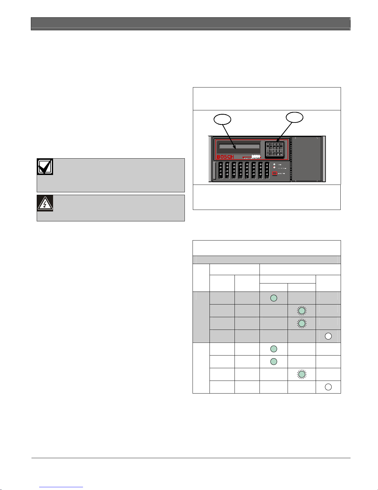
Figure 1: D6600 Communications
Receiver/Gateway (Front View)
Green
2
Clear
1
1 – LCD - Shows up to 80 characters of information
(two lines of up to 40 characters each)
2 – Keypad - The D6600 has a 20-button keypad.
Table 2 and Table 3 on page 7 show and define the
D6600/D6100i POWER and SYSTEM TROUBLE
LEDs.
Table 2: Power LED Indications
On
Off
Present Power LED Status
AC Battery
Solid Blinking
X X
X
X
X X
X
X
6 Bosch Security Systems, Inc. | 8/07 | 4998122704-02
Conettix D6600/D6100i | Installation and Operation Guide | 3.0 Card Functions and Locations
.
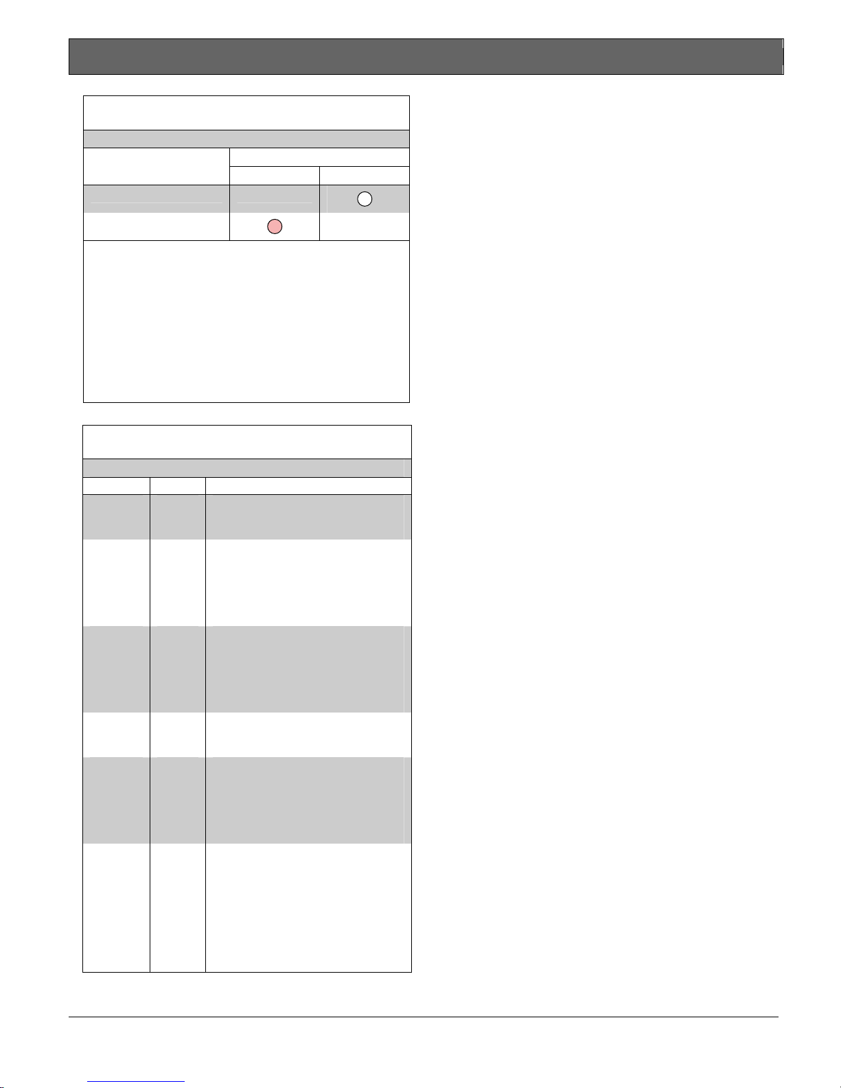
Table 3: System Trouble LED
System Trouble LED Status
Solid Red Clear
No System Trouble
Any System Trouble*
* Refer to Appendix B: D6600/D6100i Internal Messages in the
D6600/D6100i Computer Interface Manual
(P/N: 4998122703). The following items cause system
trouble. Depending on the supervision setting, the items
indicated by ** might cause system trouble.
Battery Missing**
UPS AC Fail
Battery Bad**
UPS Battery Low
AC Fail
System Temperature High
External Printing Error**
Line Fault**
COM# Error**
Line Card Trouble**
COM3 Trouble**
3.1.2 Line Cards and Modules
Table 4: D6600 Line Cards and Modules
Name Model Description
Telephone
line card
D6640
Up to eight line cards can be installed
in one D6600 Receiver, for up to 32
telephone line connections.
Telephone
line card
D6641
Functions like the D6640. Includes
improved Public Switched Telephone
Network (PSTN) processing,
additional memory for future
enhancements, and single firmware
upgrade package.
CPU card D6610
The D6600 uses one CPU card. The
CPU card takes the incoming
information from the line card and
routes the information to an
automation port, the LCD on the front
of the receiver, and an external printer.
Power
supply
modules
Telephone
line
terminator
card
D6630
and
D6631
D6645
The power supply modules regulate
the power used by the D6600. These
are not field serviceable.
Located behind the line card, the telephone line terminator card isolates
and protects the line card against outside voltage surges that might come
over the telephone line. Each line card
must have a line terminator card.
CPU
terminator
card
D6615
Located behind the CPU card, the
CPU terminator card provides the
D6600 with two serial ports (COM3
and COM4), a parallel port (parallel
printer), and a general I/O port (I/O).
The serial ports can be used for
computer automation, PC connection
for programming, or a network
connection with a D6680.
Bosch Security Systems, Inc. | 8/07| 4998122704-02 7
Conettix D6600/D6100i | Installation and Operation Guide | 3.0 Card Functions and Locations
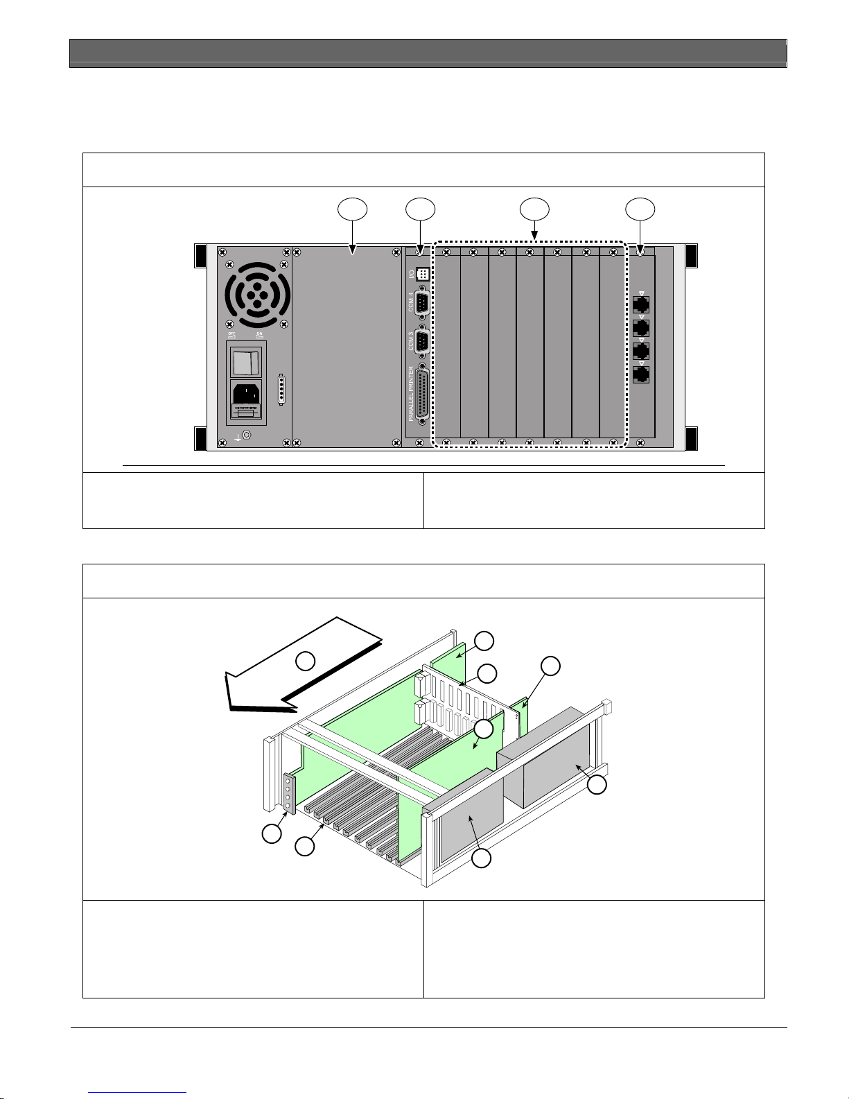
3.1.3 Rear View
The D6600 has input and output pin connector sockets for up to eight line cards, network option (if installed), and
one CPU card. It also has slots for connecting these cards to their corresponding terminator cards.
Figure 2: D6600 Communications Receiver/Gateway (Rear View)
1 2 43
Bosch Security Syste ms
Fairport, NY USA
1
2
3
B
A
T
T
E
R
Y
Input:
100 - 120/
220 - 240V~
50 - 60 Hz
2.5 Amps
4
1 – Blank plate and location of optional installed
Conettix D6672 COM1 Expansion Kit
2 – Conettix D6615 CPU Terminator Card
3.1.4 Internal View
Figure 3: Receiver Card Placement
9
8
7
3 – Card slot covers
4 – Conettix D6645 Line Terminator Card
1
2
3
5
4
6
1 – Conettix D6645 or D6645INTL Telephone Line
Terminator Card
2 – Back plate
3 – Conettix D6615 CPU Terminator Card
4 – D6630 AC/DC Power Supply (not serviceable)
8 Bosch Security Systems, Inc. | 8/07 | 4998122704-02
5 – Conettix D6610 CPU Card
6 – D6631 DC/DC Power Supply (not serviceable)
7 – Card guides
8 – Conettix D6640/D6641 Telephone Line Card
9 – Direction of receiver front

.
3.2 D6100i
The difference between the D6100 and
the D6100i is the D6100i has a built in
Ethernet connection.
3.2.1 Front Panel
Conettix D6600/D6100i | Installation and Operation Guide | 4.0 D6600 Specific Cards
4.0 D6600 Specific Cards
4.1 D6640/D6641 Line Cards and D6645
Line Terminator Card
Figure 6: D6640/D6641 Line Card
Figure 4: D6100i Communications Receiver/
Gateway (Front View)
1 – Liquid crystal display (LCD) - Displays up to 80
characters of information (two lines of up to 40
characters each)
2 – 23-button keypad
Table 2 on page 6 and Table 3 on page 7 define the
D6600/D6100i POWER and SYSTEM TROUBLE
LEDs.
3.2.2 Line Cards and Modules
The D6100i does not use the same line cards and
modules as the D6600. These functions are built in.
3.2.3 Back Plate
Figure 5: D6100i Communications Receiver/
Gateway (Rear View)
1
2
3
1 – 48-pin connection to D6645 Line Termination
Card
2 – 40-pin connection to D6600 Back Plate
3 – LEDs (refer to Figure 8 on page 10)
Figure 7: D6645 Line Terminator Card
1
1 2
1
2
3
8
7
1 – Telephone line
connections
2 – Input/output ports
3 – COM4 RS-232 port
4 – COM3 auxiliary
RS-232 port
6
5
5 – Parallel port
connection
6 – Ethernet port
(D6100i only)
7 - USB port
8 – Power connection
terminal block
3
4
2
1 – 48-pin connection to D6640/D6641 Line Card
2 – Alignment Guide - Stabilizes the connection
and acts as a guide for connecting the
terminator card to the line card.
3 – Telco Line Jacks - Standard telephone lines
connect to the RJ11C jacks.
Bosch Security Systems, Inc. | 8/07| 4998122704-02 9

Conettix D6600/D6100i | Installation and Operation Guide | 4.0 D6600 Specific Cards
4.1.1 D6640/D6641 LED Descriptions
The LED is active until the system acknowledges the
entire transmission and the telephone line is ready to
receive signals.
Figure 8: D6640/D6641 LED Descriptions
4.1.2 Card Installation
Discharge static electricity from your body
by touching the receiver’s internal frame
(unpainted section) before handling any
circuit card.
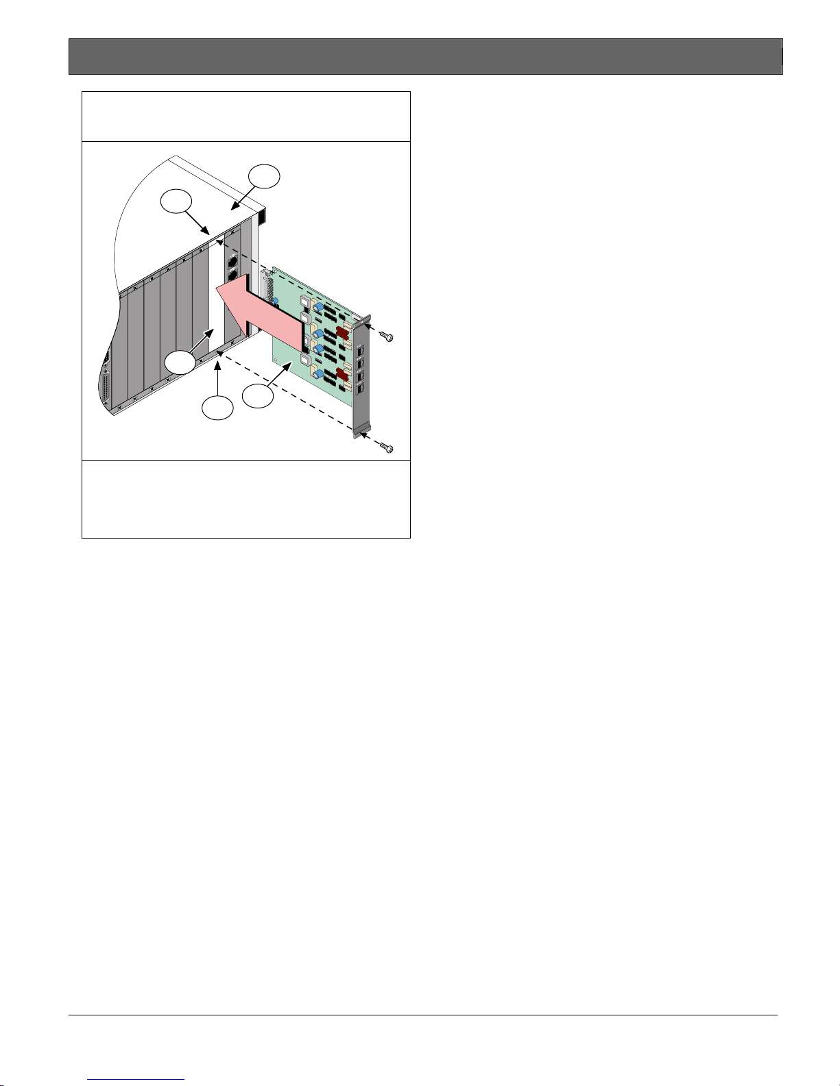
Installing Terminator Cards
Refer to Figure 9 on page 11 when performing the
following steps:
1. Remove the two bracket screws that secure the
1
2
3
4
OL/LF
1
2
3
4
terminator card (or card slot cover, if this is a new
terminator card installation) to the back of the
D6600 chassis.
2. If you are removing an existing terminator card,
open the display door on the front of the D6600
and pull the line card slightly out, then re-insert.
This will push the existing terminator card out the
back of the D6600 chassis.
3. Remove the existing terminator card.
4. Insert the new terminator card in the same slot by
1 – Flashes green when an incoming call rings.
2 – Glows green when the receiver is online with
an incoming call.
3 – Glows red when the line card detects a line
fault condition.
4 – LED is off and ready to receive signals or is
disabled in the software.
aligning the top and bottom of the terminator card
with the card guides in the D6600 chassis.
5. Slide the card into the D6600 chassis, wiggling the
card as you push until the card is flush with the
back of the chassis.
6. Secure the bracket screws at the top and bottom of
the terminator card. Ensure that the screws are
tight.
7. Repeat this process for all additional terminator
cards.
8. Connect appropriate telephone line cords to the
telephone line jack on the terminator cards.
9. Continue with Installing Line Cards on page 11.
10 Bosch Security Systems, Inc. | 8/07 | 4998122704-02
Even if you are replacing an existing
terminator card, you must proceed to
Installing Line Cards on page 11.
Conettix D6600/D6100i | Installation and Operation Guide | 4.0 D6600 Specific Cards
.
Figure 9: Removing and Installing Terminator
Card
4
2
3
1
2
4.1.3 D6640/D6641Telephone Line Monitoring
Voltage
The line card continuously monitors the telephone line
voltage. Normal operating voltage ranges from
1.8 VDC to 2.5 VDC. Any voltage above 2.5 VDC
causes the line to appear good (restoral) and an
indication appears if any voltage is below 1.8 VDC.
1 – Terminator Card (D6645 shown)
2 – Bracket screws (top and bottom)
3 – Empty slot
4 – D6600 chassis
Installing Line Cards
1. Install the terminator card(s) (refer to Installing
Terminator Cards on page 10).
2. Open the display door on the D6600.
One telephone line card is installed in the D6600
when shipped from the factory.
3. Insert the new line card into the slot by aligning
the top and bottom of the line card with the card
guides in the D6600 chassis. Firmly push the card
to make sure it is fully connected.
4. If you are installing a new telephone line card,
remove the appropriate snap-in covers from the
front of the panel.
5. Close the front panel.
6. Program the line card if necessary.
When the line card is initialized (as indicated by a
printer report), the settings in the line card
programming section automatically load into the
card.
7. Connect communication lines to the line card.
Bosch Security Systems, Inc. | 8/07| 4998122704-02 11
 Loading...