

Page 1

BVMS
en
Operation manual
Page 2

Page 3

BVMS Table of contents | en 3
Table of contents
1
1.1 Finding information 7
1.2 Printing the Help 7
2
3
3.1 Hardware requirements 12
3.2 Software requirements 12
3.3 License requirements 12
4
4.1 BVMS design concepts 13
4.1.1 Single Management Server System 13
4.1.2 Enterprise System 14
4.1.3 Server Lookup 15
4.1.4 Unmanaged site 16
4.2 Recording 17
4.2.1 Automated Network Replenishment (ANR) 17
4.3 Alarm handling 19
4.4 Inactivity logoff 20
4.5 Version independent Operator Client 21
4.5.1 Working with Compatibility Mode 21
4.6 Viewing modes of a panoramic camera 22
4.6.1 360° panoramic camera - floor- or ceiling mounted 22
4.6.2 180° panoramic camera - floor- or ceiling mounted 24
4.6.3 360° panoramic camera - wall mounted 25
4.6.4 180° panoramic camera - wall mounted 26
4.6.5 Cropped view on a panoramic camera 27
4.7 SSH Tunneling 28
5
5.1 Starting Operator Client 29
5.2 Accepting a new configuration 30
5.3 Accessing the system 30
5.4 Using Server Lookup 30
6
6.1 Selecting a time zone 32
6.2 Displaying a camera in an Image pane 33
6.3 Displaying a panoramic camera 33
6.4 Switching the viewing mode of panoramic camera 34
6.5 Displaying a dual thermal/optical camera 34
6.6 Displaying cameras from multiple Management Servers 35
6.7 Finding an item in the Logical Tree 35
6.8 Changing the number of Image pane rows 35
6.9 Arranging and resizing Image panes 36
6.10 Displaying the Alarm Image window 36
6.11 Starting manual recording 37
6.12 Starting a pre-configured camera sequence 37
6.13 Starting an automatic camera sequence 38
6.14 Using one channel audio mode 39
6.15 Using multichannel audio mode 39
Using the Help 7
Introduction 9
System overview 11
Concepts 13
Getting started 29
Displaying camera images 32
Bosch Security Systems B.V. Operation manual 2020.08 | V 1 | Operator Client
Page 4

4 en | Table of contents BVMS
6.16 Using digital zoom 40
6.17 Saving a single image 40
6.18 Printing a single image 40
6.19 Switching to full-screen mode 41
6.20 Displaying or hiding the Image pane bars 41
6.21 Displaying information on a camera 41
6.22 Enabling video content analysis (VCA) 42
6.23 Showing video content analysis (VCA) rules 42
6.24 Starting instant playback 42
6.25 Assigning a camera to a monitor 43
6.26 Using audio mode 43
6.27 Using the Intercom functionality 43
6.28 Locking the control of a PTZ camera 45
6.29 Updating the reference image 45
6.30 Displaying a monitor group 46
6.31 Controlling a monitor wall 46
6.32 Selecting live stream for display 47
6.33 Displaying video via low bandwidth 47
6.34 Using TCP for reliable connection 49
6.35 Connecting to an unmanaged site 49
6.36 Displaying a video analytics alarm 50
6.37 Displaying Intelligent Insights widgets 50
7
Using maps and the PTZ cameras 51
7.1 Displaying a map 51
7.2 Controlling PTZ cameras 51
7.3 Using in-window control of a camera 52
7.4 Using the ROI function 52
7.5 Using Intelligent Tracking 53
8
Using favorites and bookmarks 54
8.1 Adding items to the Favorites Tree 54
8.2 Creating/editing views 55
8.3 Adding a bookmark 56
8.4 Editing a bookmark 57
8.5 Loading a bookmark 57
8.6 Exporting bookmarks 57
8.6.1 Export Bookmark dialog box 58
8.6.2 Export Multiple Bookmarks dialog box 59
9
Managing recorded videos 61
9.1 Selecting a time zone 61
9.2 Finding recorded video 62
9.2.1 Video Search Results window 62
9.3 Playing recorded videos 63
9.4 Using the Timeline 63
9.5 Changing the playback speed 63
9.6 Restricting or unrestricting video 64
9.6.1 Restrict Video dialog box 64
9.6.2 Unrestrict Video dialog box 65
9.7 Protecting or unprotecting video 65
9.7.1 Protect Video dialog box 66
2020.08 | V 1 | Operator Client Operation manual Bosch Security Systems B.V.
Page 5

BVMS Table of contents | en 5
9.7.2 Unprotect Video dialog box 66
9.8 Deleting video data 67
9.9 Verifying the authenticity of video data 67
9.9.1 Authenticity verification result dialog box 68
9.10 Exporting video data 69
9.10.1 Exporting a time period 71
9.10.2 Exporting a single search entry 71
9.10.3 Exporting into a single file 72
9.10.4 Providing a password for export 72
9.10.5 Export Video dialog box 73
9.10.6 Export dialog box 74
9.11 Loading exported video 75
9.12 Enabling video content analysis (VCA) 75
9.13 Performing a Forensic Search 76
9.14 Forensic Search Results window 77
9.15 Finding logbook entries 77
9.15.1 Finding logons to an unmanaged site 78
9.15.2 Please select a Server 78
9.15.3 Select Search Parameters dialog box 78
9.15.4 Event Selection dialog box 82
9.15.5 Device Selection dialog box 82
9.15.6 Search Conditions dialog box 82
9.15.7 Logbook Results: dialog box 82
9.16 Displaying text data 83
9.17 Searching for text data 84
9.18 Searching for text data in logbook entries 85
9.19 Erasing text data from logbook entries 85
9.20 Displaying video via low bandwidth 86
9.21 Switching the recording source 87
9.22 Connecting to an unmanaged site 88
10
Handling events and alarms 90
10.1 Accepting an alarm 90
10.2 Adding comments to an alarm 91
10.3 Clearing an alarm 91
10.4 Customizing the Alarm List window 92
10.5 Displaying the Live Image window 92
10.6 Switching alarm modes of Alarm Image window 92
10.7 Starting a workflow 93
10.8 Un-accepting an alarm 93
10.9 Triggering a user event 94
10.10 Alarm List window 94
11
Managing Person Identification alarms 95
11.1 Managing persons for a Person Identification alarm 95
12
Controlling intrusion panel functions 97
12.1 Switching off alarm sirens 97
12.2 Operating doors 97
12.3 Bypassing a point 97
12.3.1 Arming an area 98
13
Controlling access control functions 99
Bosch Security Systems B.V. Operation manual 2020.08 | V 1 | Operator Client
Page 6

6 en | Table of contents BVMS
13.1 Granting and denying access 99
13.2 Operating doors 99
14
Using a CCTV keyboard 100
14.1 Using KBD Universal XF keyboard 100
14.1.1 KBD Universal XF keyboard user interface 100
14.2 Bosch IntuiKey keyboard user interface 102
14.2.1 Status display 103
14.3 Using a Bosch IntuiKey keyboard connected to a workstation 103
14.3.1 Starting the keyboard 104
14.3.2 Entering operation modes 104
14.3.3 Displaying cameras 104
14.3.4 Using the joystick 105
14.3.5 Using softkeys 105
14.4 Using a Bosch IntuiKey keyboard connected to a decoder 107
14.4.1 Starting the keyboard 107
14.4.2 Displaying cameras 108
14.4.3 Using the joystick 108
14.4.4 Using softkeys 108
15
User interface 109
15.1 Live Mode 109
15.2 Playback Mode 111
15.3 Alarm Mode (Alarm Display) 113
15.4 Icons used 115
15.5 Menu commands 119
15.6 Options dialog box 122
15.6.1 Control tab 123
15.6.2 Display tab 123
15.6.3 Audio tab 124
15.6.4 Transcoding tab 124
15.7 Logical Tree window 124
15.8 Favorites Tree window 125
15.9 Bookmarks window 125
15.10 Image window 126
15.11 Image pane 127
15.12 Search box 127
15.13 Exports window 128
15.14 Map window 128
15.15 Monitor Wall Image window 128
15.16 PTZ Control window 129
15.17 Timeline window 130
16
Keyboard shortcuts 132
16.1 General controls 132
16.2 Playback controls 132
16.3 Image window controls 132
17
Troubleshooting 133
17.1 Reestablishing the connection to a Bosch IntuiKey keyboard 134
Glossary 135
Index 140
2020.08 | V 1 | Operator Client Operation manual Bosch Security Systems B.V.
Page 7

BVMS Using the Help | en 7
1 Using the Help
To find out more about how to do something in BVMS, access the online Help using any of the
following methods.
To use the Contents, Index, or Search:
4 On the Help menu, click Display Help. Use the buttons and links to navigate.
To get help on a window or dialog:
4 On the toolbar, click .
OR
4 Press F1 for help on any program window or dialog.
1.1 Finding information
You can find information in the Help in several ways.
To find information in the Online Help:
1. On the Help menu, click Help.
2. If the left-hand pane is not visible, click the Show button.
3. In the Help window, do the following:
Click: To:
Contents Display the table of contents for the Online Help. Click each book to
display pages that link to topics, and click each page to display the
corresponding topic in the right-hand pane.
Index Search for specific words or phrases or select from a list of index
keywords. Double-click the keyword to display the corresponding topic
in the right-hand pane.
Search Locate words or phrases within the content of your topics. Type the
word or phrase in the text field, press ENTER, and select the topic you
want from the list of topics.
Texts of the user interface are marked bold.
4 The arrow invites you to click on the underlined text or to click an item in the application.
Related Topics
4 Click to display a topic with information on the application window you currently use.
This topic provides information on the application window controls.
Concepts, page 13
Notice!
This symbol indicates a potential risk of property damage or data loss.
provides background information on selected issues.
1.2 Printing the Help
While using the Online Help, you can print topics and information right from the browser
window.
To print a Help topic:
1. Right-click in the right pane and select Print.
The Print dialog box opens.
2. Click Print.
Bosch Security Systems B.V. Operation manual 2020.08 | V 1 | Operator Client
Page 8

8 en | Using the Help BVMS
P The topic is printed to the specified printer.
2020.08 | V 1 | Operator Client Operation manual Bosch Security Systems B.V.
Page 9

BVMS Introduction | en 9
2 Introduction
Click the link to access the Open Source Software licenses used by BVMS and the Mobile App:
http://www.boschsecurity.com/oss/
Covered by one or more claims of the patents listed at patentlist.hevcadvance.com.
1 Menu bar Allows you to select a menu command.
2 Toolbar Displays the available buttons. Point to an icon to
display a tooltip.
3 Playback controls Allows you to control instant playback or a camera
sequence or alarm sequence.
4 Performance meter Displays the CPU usage and the memory usage.
5 Time zone selector Select an entry for the time zone to be displayed in
most time related fields.
Only available if at least one Management Server or
unmanaged site in the Logical Tree is located in
another time zone as your OperatorClient.
6 Controls for Image panes Allows you to select the required number of Image
panes and to close all Image panes.
7 Image window Displays the Image panes. Allows you to arrange the
Image panes.
8 Image pane Displays a camera, a map, an image, a document
(HTML file).
Bosch Security Systems B.V. Operation manual 2020.08 | V 1 | Operator Client
Page 10
10 en | Introduction BVMS
9
10
11
Alarm List window
PTZ Control window
Logical Tree window
Favorites Tree window
Bookmarks window
Map window
Displays all alarms that the system generates.
Allows you to accept or clear an alarm or to start a
workflow, for example, by sending an E-mail to a
maintenance person.
The Alarm List is not being displayed, when the
connection to the Management Server is lost.
Allows you to control a PTZ camera.
Displays the devices your user group has access to.
Allows you to select a device for assigning it to an
Image pane.
Allows you to organize the devices of the Logical Tree
as required.
Allows to manage bookmarks.
Displays a site map. Allows you to drag the map to
display a particular section of the map.
If activated, a map is displayed automatically for each
camera displayed in an Image pane. In this case, the
camera must be configured on a map.
This manual guides you through the basic steps of the configuration and operation with BVMS.
For detailed help and step-by-step instructions read the Configuration Manual and the User
Manual or use the Online Help.
BVMS Export Player displays exported recordings.
2020.08 | V 1 | Operator Client Operation manual Bosch Security Systems B.V.
Page 11

BVMS System overview | en 11
3 System overview
If you plan to install and configure BVMS, participate in a system training on BVMS.
Refer to the Release Notes of the current BVMS version for supported versions of firmware
and hardware and other important information.
See data sheets on Bosch workstations and servers for information on computers where
BVMS can be installed.
The BVMS software modules can optionally be installed on one PC.
Important components
Component Description
Management Server (selectable
in Setup)
Config Wizard Easy and fast setup of a recording system.
ConfigurationClient (selectable
in Setup)
OperatorClient (selectable in
Setup)
Video Recording Manager
(selectable in Setup)
Mobile Video Service
(selectable in Setup)
Stream management, alarm management, priority
management, Management logbook, user management,
device state management. Additional Enterprise System
license: Managing Enterprise User Groups and Enterprise
Accounts.
System configuration and administration for
OperatorClient.
Live monitoring, storage retrieval and playback, alarm and
accessing multiple Management Server computers
simultaneously.
Distributing storage capacities on iSCSI devices to the
encoders, while handling load balancing between multiple
iSCSI devices.
Streaming playback video and audio data from iSCSI to
Operator Clients.
Provides a transcoding service that transcodes the live and
recorded video stream from a camera configured in BVMS
to the available network bandwidth. This service enables
video clients like an iPhone or a Web client to receive
transcoded streams, for example for unreliable network
connections with limited bandwidth.
Web Client You can access live and playback videos via Web browser.
Mobile App You can use the Mobile App on iPhone or iPad to access
live and playback video.
Bosch Video Streaming Gateway
(selectable in Setup)
CameoSDK (selectable in
Setup)
Bosch Security Systems B.V. Operation manual 2020.08 | V 1 | Operator Client
Provides the integration of 3rd party cameras and NVR-like
recording, e.g. in low-bandwidth networks.
The CameoSDK is used to embed BVMS live and playback
Image panes to your external third-party application. The
Image panes follow the BVMS based user permissions.
The CameoSDK provides a subset of the BVMS
OperatorClient functionalities that enables you to create
applications similar to the OperatorClient.
Page 12

12 en | System overview BVMS
Component Description
Client EnterpriseSDK The Client EnterpriseSDK is meant to control and monitor
the behaviour of OperatorClient of an Enterprise System
by external applications. The SDK allows to browse devices
that are accessible by the running, connected
OperatorClient and to control some UI functionalities.
ClientSDK / ServerSDK The ServerSDK is used to control and monitor the
Management Server by scripts and external applications.
You can use those interfaces with a valid administrator
account.
The ClientSDK is used to control and monitor the
OperatorClient by external applications and scripts (part
of the related server configuration).
3.1 Hardware requirements
See the data sheet for BVMS. Data sheets for platform PCs are also available.
3.2 Software requirements
See the data sheet for BVMS.
3.3 License requirements
See the data sheet for BVMS for the available licenses.
2020.08 | V 1 | Operator Client Operation manual Bosch Security Systems B.V.
Page 13
BVMS Concepts | en 13
4 Concepts
This chapter provides background information on selected issues.
4.1 BVMS design concepts
Single Management Server System, page 13
A single BVMS Management Server System provides management, monitoring and control of
up to 2000 cameras/encoders.
Enterprise System, page 14
An Enterprise Management Server provides simultaneous access to multiple
ManagementServers. The Enterprise System allows full access to events and alarms from
multiple subsystems.
Server Lookup, page 15
The Server Lookup feature provides a list of available BVMS ManagementServers to the BVMS
OperatorClient. The Operator can select a server out of the list of available server. Connected
to the Management Server the Client has full access to the Management Server.
Unmanaged site, page 16
Devices can be grouped to unmanaged sites. Devices under unmanaged sites are not
monitored by the Management Server. The Management Server provides a list of unmanaged
sites to the OperatorClient. The Operator can connect on demand to the site and gets access
to live video data and recorded video data. Event and alarm handling is not available in the
unmanaged site concept.
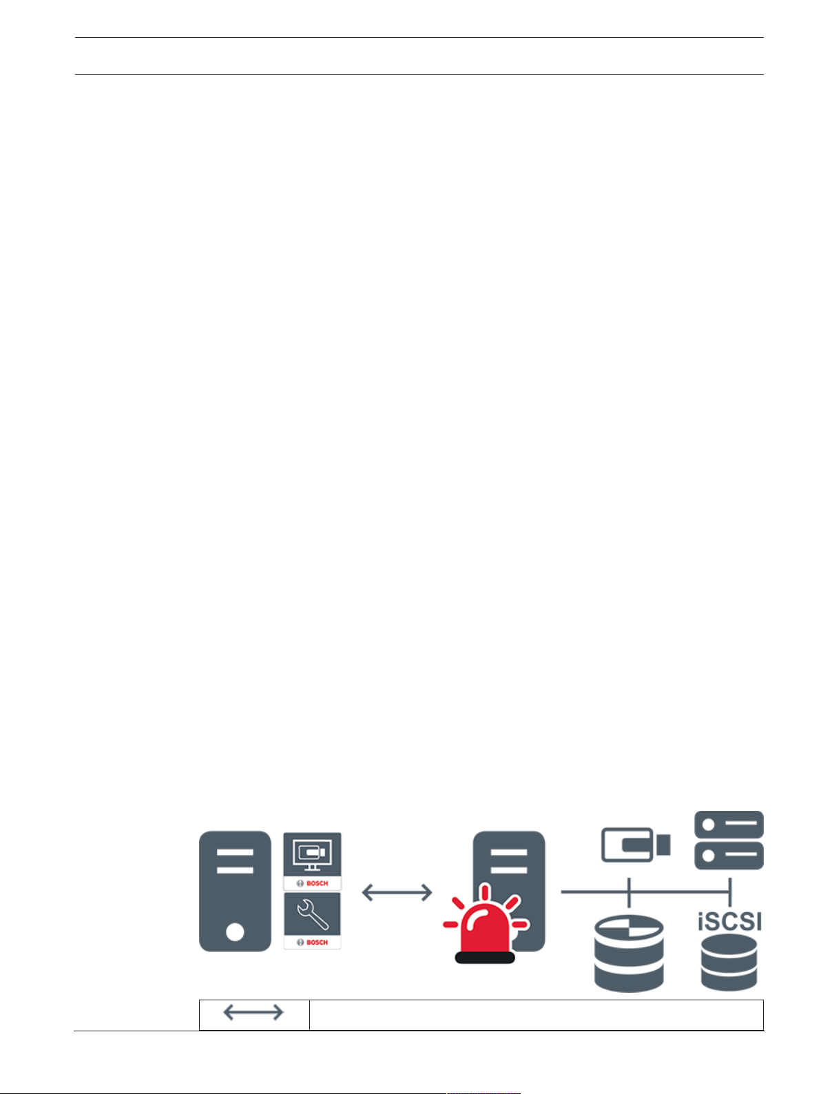
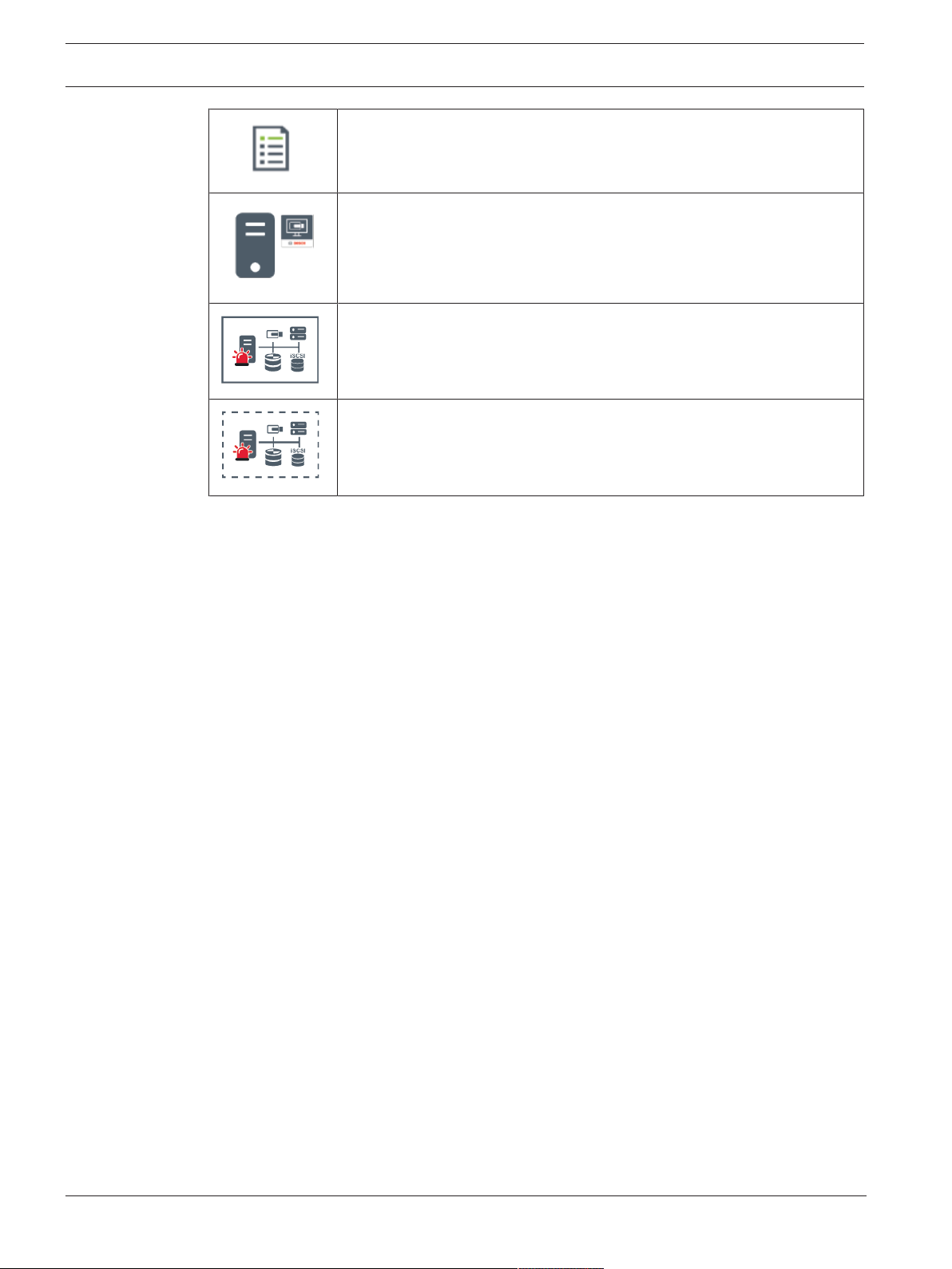
4.1.1 Single Management Server System
– A single BVMS Management Server can manage up to 2000 channels.
– A BVMS Management Server provides management, monitoring, and control of the entire
system.
– The BVMS OperatorClient is connected to the Management Server and receives events
and alarms from the BVMS Management Server and shows live and playback.
– In most cases all devices are in one local area network with a high bandwidth and a low
latency.
Responsibilities:
– Configuring data
– Event log (logbook)
– User profiles
– User priorities
– Licensing
– Event- and alarm-management
Live, playback, events, alarms
Bosch Security Systems B.V. Operation manual 2020.08 | V 1 | Operator Client
Page 14
14 en | Concepts BVMS
Management Server
OperatorClient / ConfigurationClient
Cameras
VRM
iSCSI
Other devices
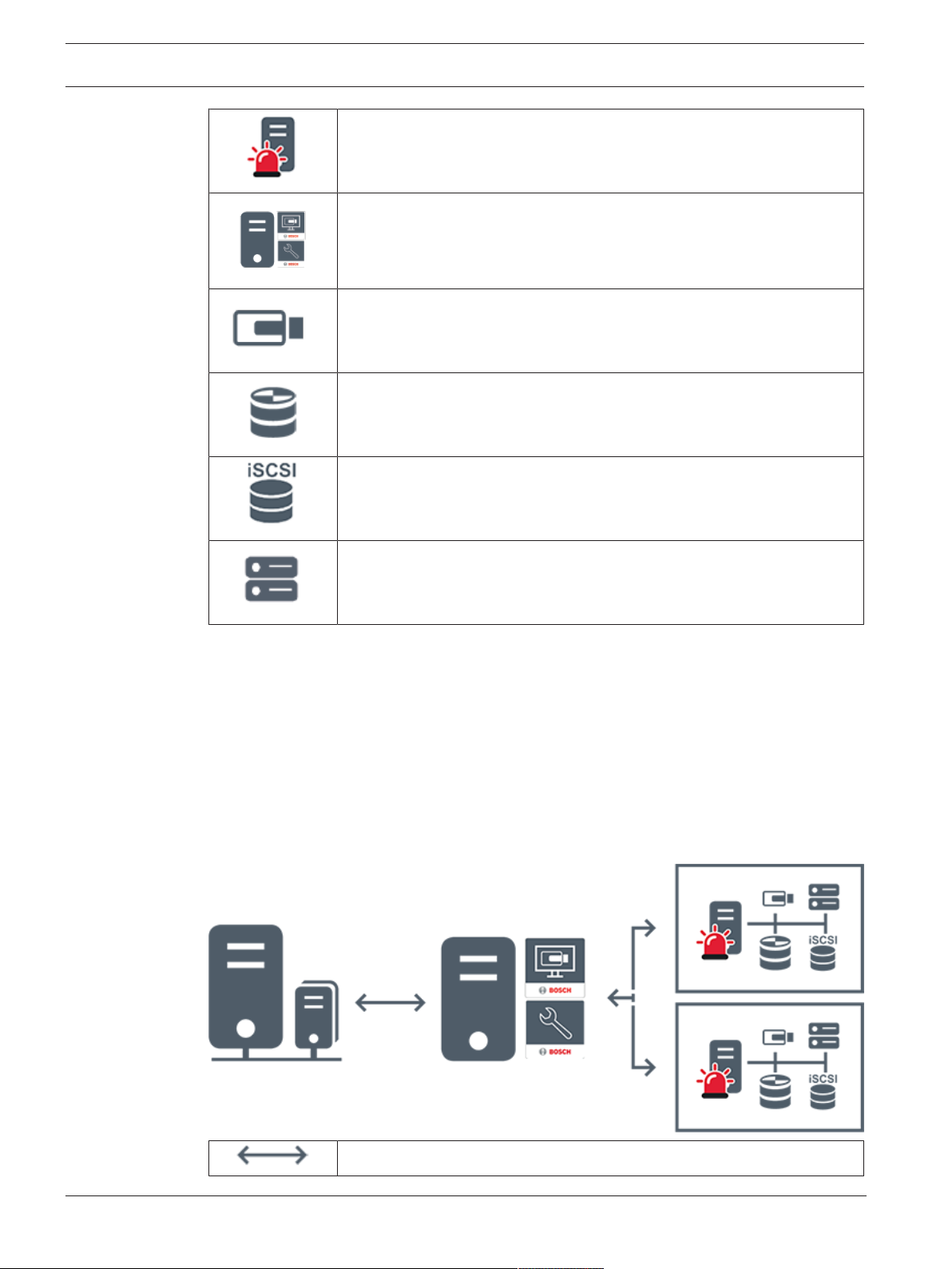
4.1.2 Enterprise System
– The target of a BVMS Enterprise System is to enable a user of an Operator Client to
simultaneously access multiple ManagementServers (subsystems).
– Clients connected to an Enterprise Server have full access to all cameras and recordings
from the subsystems.
– Clients connected to an Enterprise Server have full real time awareness of events and
alarms of all subsystems.
– Typical application areas:
– Metros
– Airports
Live, playback, events, alarms
2020.08 | V 1 | Operator Client Operation manual Bosch Security Systems B.V.
Page 15
BVMS Concepts | en 15
BVMS Enterprise Management Server
BVMS OperatorClient / ConfigurationClient
BVMS Subsystem
Refer to
– Accessing the system, page 30
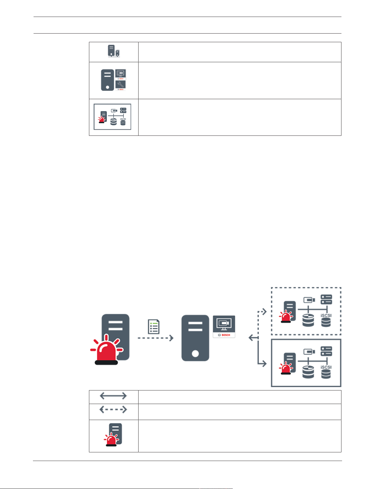
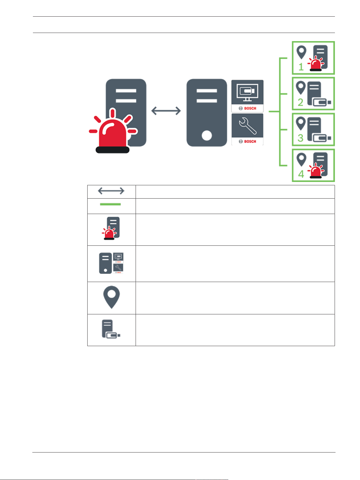
4.1.3 Server Lookup
– The BVMS Server Lookup feature allows Operators to connect to a BVMS Management
Server out of a provided list of servers.
– A single user of ConfigurationClient or OperatorClient can connect to multiple system
access points sequentially.
– System access points can be Management Server or Enterprise Management Server.
– Server Lookup uses dedicated Management Server to host the Server List.
– Server Lookup and Management Server or Enterprise Management Server functionally can
be run on one machine.
– Server Lookup supports you in locating system access points by their names or
descriptions.
– Once connected to the Management Server the OperatorClient receives events and
alarms from the BVMS Management Server and shows live and playback
On demand live, playback, events, alarms - connected
On demand live, playback, events, alarms - not connected
Management Server
Bosch Security Systems B.V. Operation manual 2020.08 | V 1 | Operator Client
Page 16
16 en | Concepts BVMS
Server list
OperatorClient
Connected BVMS from server list
Not connected BVMS from server list
Refer to
– Using Server Lookup, page 30
4.1.4 Unmanaged site
– A system design option in BVMS with a large number of small subsystems.
– It allows to configure up to 9999 locations in one BVMS Management Server
– Operators can access live and recorded video data from up to 20 sites simultaneously.
– For an easy navigation sites can be grouped in folders or can be placed on maps.
Predefined username and password allow operators to quickly connect to a site .
The unmanaged site concept supports IP based BVMS system as well as analog DVR solutions:
– Bosch DIVAR AN 3000 / 5000 analog recorders
– DIVAR hybrid recorders
– DIVAR network recorders
– DIP 3000/7000 units IP based recording
– Single BVMS Management Server System
Adding a site for central monitoring only requires a license per site and is independent of the
number of channels in thesite.
2020.08 | V 1 | Operator Client Operation manual Bosch Security Systems B.V.
Page 17
BVMS Concepts | en 17
Live, playback, events, alarms
4.2 Recording
This chapter explains the different recording and replay related functions in the system.
On demand live and playback video traffic
Management Server
OperatorClient / ConfigurationClient
site
DVR
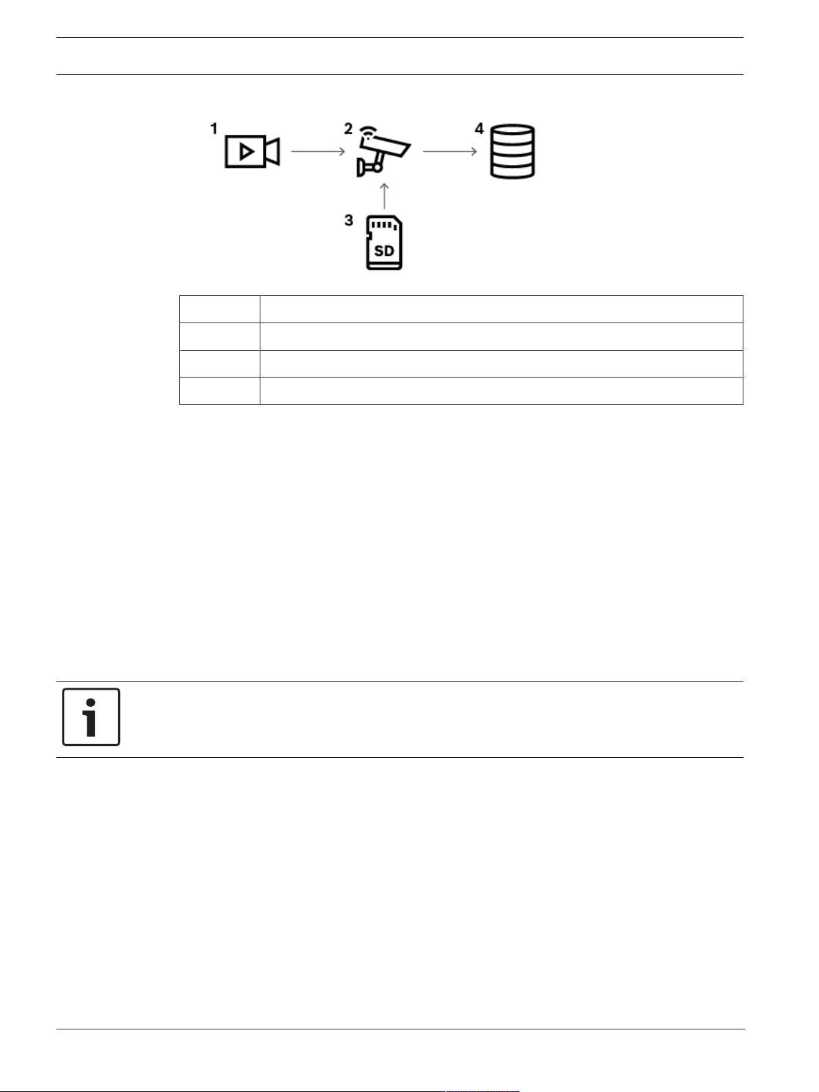
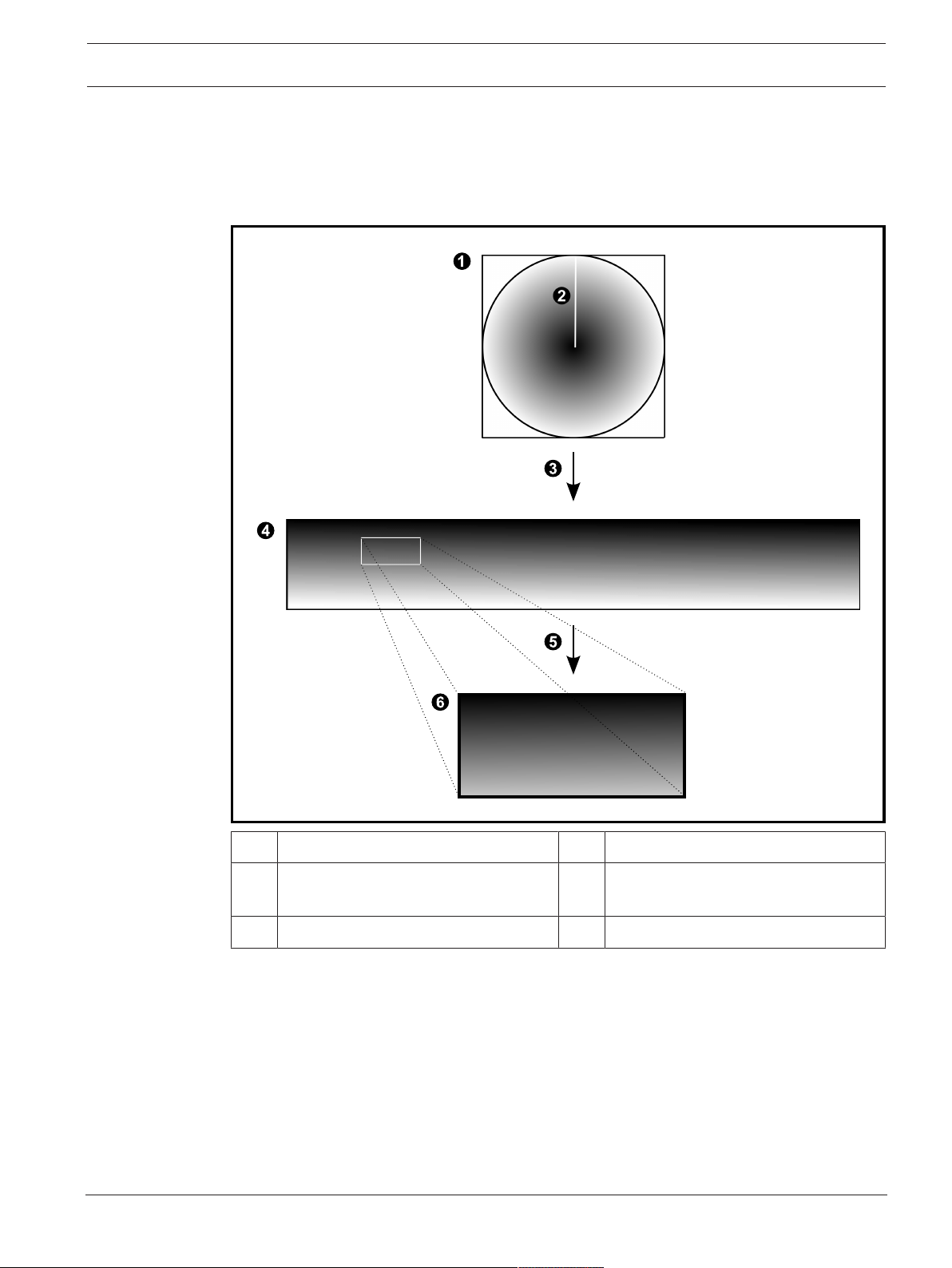
4.2.1 Automated Network Replenishment (ANR)
Intended use
When a failure of the network or the central storage occurs, the ANR function ensures that the
encoder transmits the locally buffered recording of the missing time period to the central
storage after the failure is fixed.
The following graphic shows the transmission of video data after a network or storage failure
is fixed.
Bosch Security Systems B.V. Operation manual 2020.08 | V 1 | Operator Client
Page 18
18 en | Concepts BVMS
1 Video
2 Encoder, IP network
3 SD card (ring buffer)
4 iSCSI target (central storage)
Example: Work around network failure
If the network fails unexpectedly, the ANR function completes the central storage with the
locally buffered recording when the network is available again.
Example: Store video data when network is not available
A subway has no network connection to the central storage when located between stations.
Only during regular stops the buffered recording can be transmitted to the central storage.
Ensure that the time period that is required for transferring the buffered recording, does not
exceed the time period of a stop.
Example: ANR for alarm recording
The pre-alarm recording is stored locally. Only in case of an alarm, this pre-alarm recording is
transmitted to the central storage. If no alarm occurs, the obsolete pre-alarm recording is not
transmitted to the central storage and, hence, does not burden the network.
Limitations
Notice!
You cannot use playback from the local storage media when the passwords for `user` and
`live` are set on the encoder. Remove the passwords if required.
The ANR function only works with VRM recording.
The ANR function does not work with an encoder for which a secure connection for live
display is configured.
You must have configured the storage media of an encoder to use the ANR function.
The encoder for which you configure the ANR function, must have firmware version 5.90 or
later. Not all encoder types support the ANR function.
You cannot use the ANR function with dual recording.
Your iSCSI storage system must be properly configured.
The following list contains the possible reasons if you cannot configure the ANR function:
– Encoder is not reachable (wrong IP address, network failure, etc.).
– Storage media of the encoder not available or read-only.
– Wrong firmware version.
2020.08 | V 1 | Operator Client Operation manual Bosch Security Systems B.V.
Page 19

BVMS Concepts | en 19
– Encoder type does not support the ANR function.
– Dual recording is active.
4.3 Alarm handling
Alarms can be individually configured to be handled by one or more user groups. When an
alarm occurs, it appears in the Alarm List of all users in the user groups configured to receive
that alarm. When any one of these users starts to work on the alarm, it disappears from the
Alarm List of all other users.
Alarms are displayed on a workstation’s alarm monitor. This behavior is described in the
following paragraphs.
Alarm flow
1. An alarm occurs in the system.
2. Alarm notifications appear in the Alarm Lists of all users configured for this alarm. Alarm
video is immediately displayed on configured monitors. If it is an automatically displayed
alarm (auto pop-up), the alarm video is also automatically displayed on the
OperatorClient workstation’s alarm monitors.
If the alarm is configured as an auto-clear alarm, the alarm is removed from the Alarm List
after the auto-clear time (configured in the ConfigurationClient).
On monitors, any quad views from VIPXDs are temporarily replaced by full-screen
displays.
3. One of the users accepts the alarm. The alarm video is then displayed on this user's
workstation (if it is not already displayed via auto pop-up). The alarm is removed from all
other Alarm Lists and alarm video displays.
4. The user who accepted the alarm invokes a workflow that can include reading an action
plan and entering comments. This step is optional - requirements for workflow can be
configured by the administrator.
5. Finally, the user clears the alarm. This removes the alarm from his Alarm List and alarm
display.
On a monitor group, the monitors return to the cameras that were displayed before the
alarm occurred.
Alarm Image window
1. To display alarm video, the Alarm Image window replaces the Live or Playback Image
window on the monitor that has been configured for alarm display.
2. Each alarm gets a row of Image panes. Up to 5 Image panes can be associated with each
alarm. These Image panes can display live video, playback video, or maps.
On a monitor group, each alarm can call up cameras on a row of monitors. The number of
cameras in the row is limited by the number of columns in the monitor group. Monitors in
the row that are not used for alarm video can be configured to either continue with their
current display or to display a blank screen.
3. Higher priority alarms are displayed above lower priority alarms on both monitor rows
and the OperatorClient workstation display alarm rows.
4. If the Alarm image window is completely full of Alarm image rows and an additional alarm
must be displayed, the lowest priority alarms "stack up" in the bottom row of the Alarm
image window. You can step through the stacked alarms with the controls at the left side
of the alarm row.
You can step through the alarm stacks on monitor groups with control buttons in the
Monitors window of the OperatorClient workstation display. Monitors in alarm are
indicated by red icons with blinking "LEDs".
Bosch Security Systems B.V. Operation manual 2020.08 | V 1 | Operator Client
Page 20
20 en | Concepts BVMS
The alarm title, time, and date can be optionally be displayed on all monitors, or only the
first monitor in the alarm row.
5. For equal priority alarms, the administrator can configure the order behavior:
– Last-in-First-out (LIFO) mode: in this configuration, new alarms are inserted above
older alarms of the same priority.
– First-in-First-out (FIFO) mode; in this configuration, new alarms are inserted below
older alarms of the same priority.
6. An alarm's Image row can appear in the Alarm Image window in one of two ways:
– When it is generated (auto pop-up). This occurs when the alarm priority is higher
than display priority.
– When the alarm is accepted. This occurs when the alarm priority is lower than
display priority.
Auto pop-up alarms
Alarms can be configured to automatically display (pop up) in the Alarm Image window, based
on the alarm priority. Each user group's live and playback displays are also assigned priorities.
When alarms are received with priority higher than that of the user's display, the alarm
automatically displays its alarm row in the Alarm Image window. If the Alarm Image window is
not currently displayed, it automatically replaces the Live or Playback Image window on the
alarm-enabled monitor.
Although auto pop-up alarms are displayed in the Alarm Image window, they are not
automatically accepted. They can be displayed on multiple users' displays simultaneously.
When a user accepts an auto pop-up alarm, it is removed from all other users Alarm Lists and
alarm displays.
Alarm handling in case of shutdown
On a server shutdown all active alarms are preserved. The alarms are restored and reappear in
the Alarm List window, when the system restarts.
Alarms in the state Accepted or Workflow are automatically set back to the state Active when
the system restarts. Comments entered for alarms in the state Workflow are preserved.
Notice!
The alarm data is automatically saved every minute, so the maximum data loss is the data
accumulated in one minute.
Refer to
– Alarm Mode (Alarm Display), page 113
– Handling events and alarms, page 90
4.4 Inactivity logoff
Intended use
Intended use of inactivity logoff is to protect an OperatorClient or ConfigurationClient during
the absence of the operator or administrator.
You can configure per user group that OperatorClient shall be logged off automatically after a
specified time period without activity.
For ConfigurationClient no user groups are available. The inactivity logoff setting is valid only
for the admin user.
All operations with keyboard, mouse and CCTV keyboard affect the specified time period for
inactivity logoff. Automatic activities of OperatorClient do not affect the time period.
Automatic activities of ConfigurationClient like firmware upload or iSCSI setup prevent the
inactivity logoff.
2020.08 | V 1 | Operator Client Operation manual Bosch Security Systems B.V.
Page 21

BVMS Concepts | en 21
You can also configure the inactivity logoff for a BVMS Web Client.
Short before an inactivity logoff, a dialog box reminds the user to actively prevent the
inactivity logoff.
The Logbook records an occurred inactivity logoff.
Example
If a workstation is located in a public area, the inactivity logoff minimizes the risk that on an
unattended workstation OperatorClient is accessed by an unauthorized person.
An administrator group member shall logoff automatically after inactivity but a desk officer
(operator group) might just watch video without operating the system and does not want an
inactivity logoff.
Limitations
ClientSDK activity does not support the inactivity logoff, this means that the activity of
ClientSDK does not affect the specified time period.
4.5 Version independent Operator Client
For Compatibility Mode both OperatorClient and Management Server must have a
versionlater than 5.5.
A user of OperatorClient can successfully log on to a Management Server where a previous
software version is running.
If the server provides a newer configuration than available on the OperatorClient workstation,
this configuration is automatically copied to the OperatorClient workstation. The user can
decide to download the new configuration.
OperatorClient provides a reduced feature set and is connected to this Management Server.
The following Management Server related features are available after logon to a Management
Server with a previous version:
– User preferences
– Start manual recording
– Display of device states
– Toggling relay states
– Searching the Logbook
Search for events is not possible.
– Server Lookup
– Remote export
4.5.1 Working with Compatibility Mode
This feature is available in versions later than 5.5.
A BVMS OperatorClient gives you a visual and textual feedback of its states.
Following OperatorClient states are possible:
–
The OperatorClient is connected to the Management Server.
–
The OperatorClient is not connected to the Management Server. One reason can be a
physical disconnection from the Management Server to the network.
–
Bosch Security Systems B.V. Operation manual 2020.08 | V 1 | Operator Client
Page 22

22 en | Concepts BVMS
This state can only be displayed after a reestablished connection to the Management
Server. All affected functions are back, but the configuration of the OperatorClient is
outdated due to a newer configuration available in the system. Log on again to update the
configuration.
–
This state icon is displayed when the Management Server has an earlier BVMS version
than the OperatorClient workstation.
4.6 Viewing modes of a panoramic camera
This chapter illustrates the viewing modes of a panoramic camera which are available in
BVMS.
The following viewing modes are available:
– Circle view
– Panorama view
– Cropped view
Panorama and cropped view modes are created by the dewarping process in BVMS. Edge
dewarping is not used.
The administrator must configure the mounting position of a panoramic camera in
ConfigurationClient.
You can resize the Image pane of a camera as required. The Image pane ratio is not restricted
to the 4:3 or 16:9 aspect ratio.
Refer to
– Displaying a panoramic camera, page 33
– Switching the viewing mode of panoramic camera, page 34
– Arranging and resizing Image panes, page 36
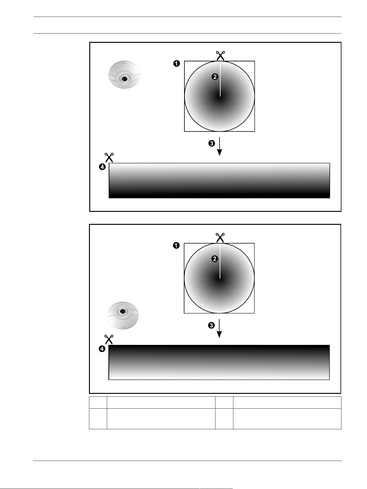
4.6.1 360° panoramic camera - floor- or ceiling mounted
The following figure illustrates the dewarping of a 360° camera which is floor- or ceiling
mounted.
2020.08 | V 1 | Operator Client Operation manual Bosch Security Systems B.V.
Page 23
BVMS Concepts | en 23
1 Full circle image 3 Dewarping
2 Snipping line (operator can change its
4 Panorama view
position when not zoomed in)
Bosch Security Systems B.V. Operation manual 2020.08 | V 1 | Operator Client
Page 24
24 en | Concepts BVMS
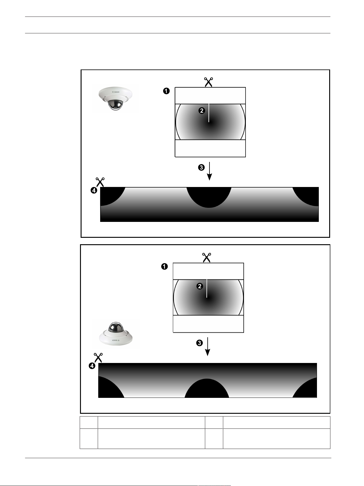
4.6.2 180° panoramic camera - floor- or ceiling mounted
The following figure illustrates the dewarping of a 180° camera which is floor- or ceiling
mounted.
1 Full circle image 3 Dewarping
2 Snipping line (operator can change its
4 Panorama view
position when not zoomed in)
2020.08 | V 1 | Operator Client Operation manual Bosch Security Systems B.V.
Page 25
BVMS Concepts | en 25
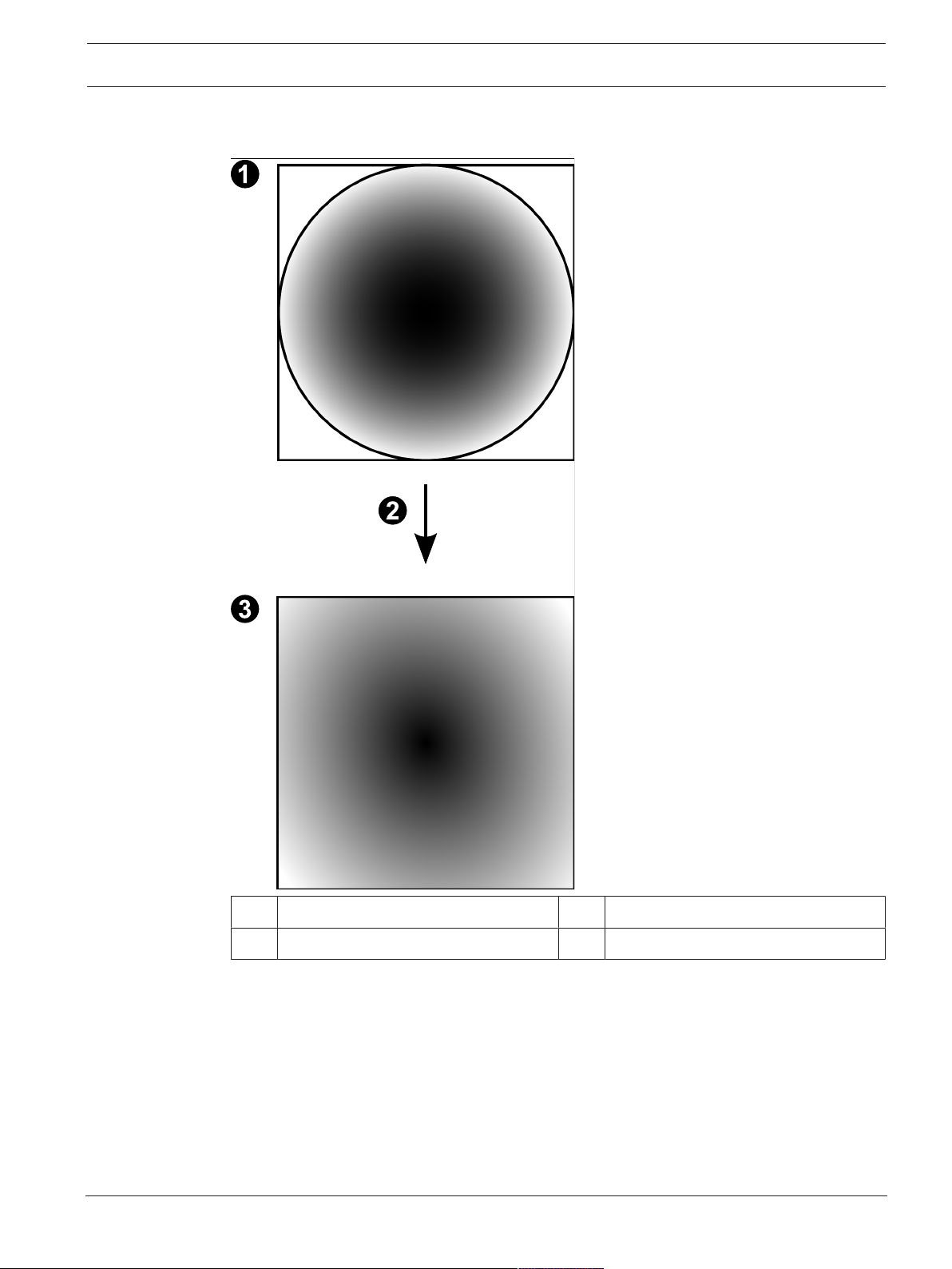
4.6.3 360° panoramic camera - wall mounted
The following figure illustrates the dewarping of a 360° camera which is wall mounted.
1 Full circle image 3 Panorama view
2 Dewarping
Bosch Security Systems B.V. Operation manual 2020.08 | V 1 | Operator Client
Page 26
26 en | Concepts BVMS
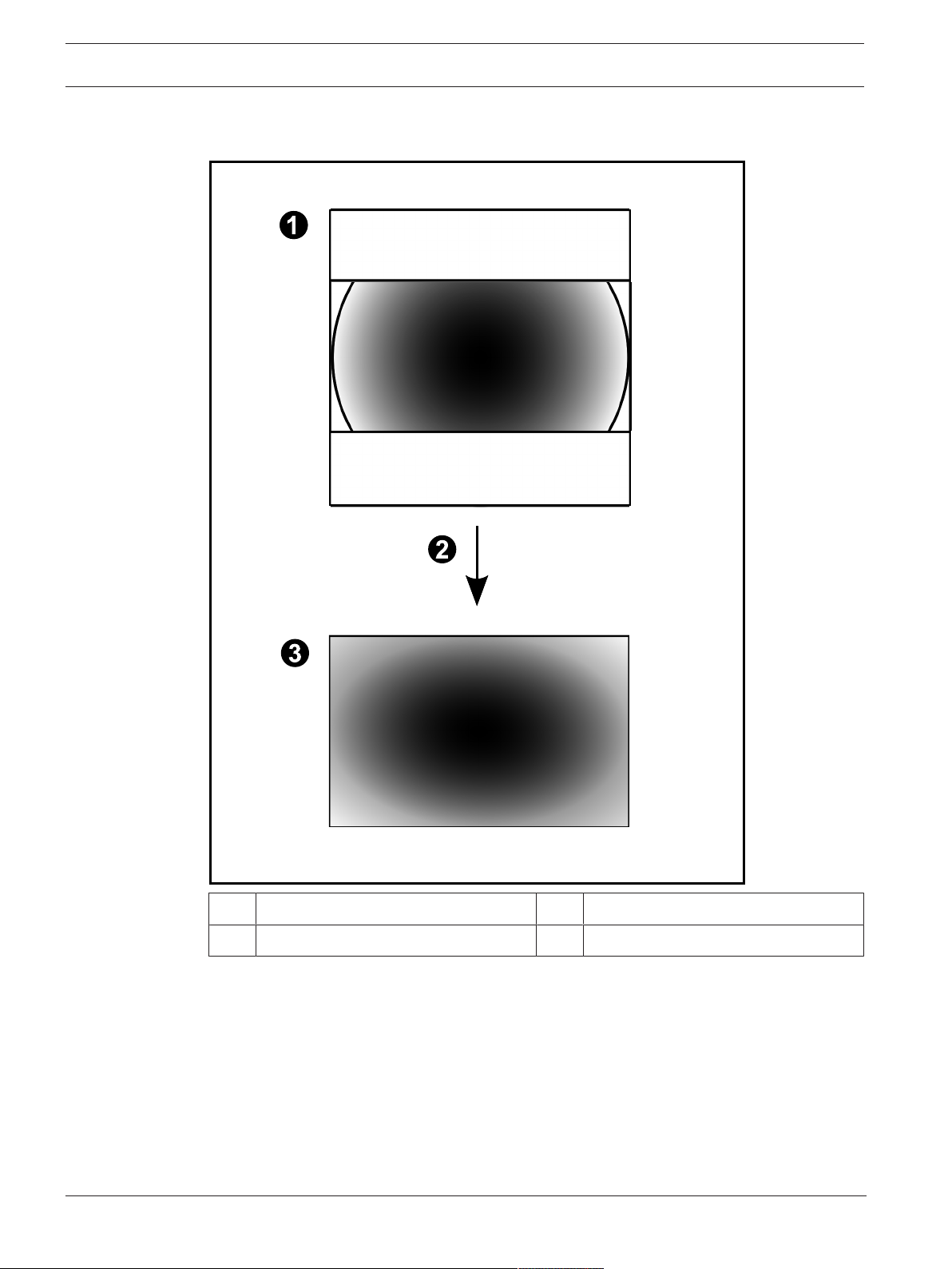
4.6.4 180° panoramic camera - wall mounted
The following figure illustrates the dewarping of a 180° camera which is wall mounted.
1 Full circle image 3 Panorama view
2 Dewarping
2020.08 | V 1 | Operator Client Operation manual Bosch Security Systems B.V.
Page 27
BVMS Concepts | en 27
4.6.5 Cropped view on a panoramic camera
The following example figure illustrates the cropping of a 360° camera which is floor- or ceiling
mounted.
The rectilinear section used for cropping is fixed. You can change the section in the cropped
Image pane using the available PTZ controls.
1 Full circle image 4 Panorama view
2 Snipping line (operator can change its
5 Cropping
position when not zoomed in)
3 Dewarping 6 Cropped Image pane
Bosch Security Systems B.V. Operation manual 2020.08 | V 1 | Operator Client
Page 28

28 en | Concepts BVMS
4.7 SSH Tunneling
BVMS provides remote connectivity utilizing Secure Shell (SSH) tunneling.
SSH tunneling constructs an encrypted tunnel established by an SSH protocol/socket
connection. This encrypted tunnel can provide transport to both encrypted and un-encrypted
traffic. The Bosch SSH implementation also utilizes Omni-Path protocol, which is a high
performance low latency communications protocol developed by Intel.
Technical aspects and restrictions
– SSH tunneling utilizes port 5322. This port cannot be modified.
– The SSH Service must be installed on the same server as the BVMS Management Server.
– (Enterprise) user accounts must have a configured password. (Enterprise) user accounts
without a password cannot log on utilizing a SSH connection.
– Local storage cameras do not support SSH connection.
– ConfigurationClient cannot connect remotely via SSH. ConfigurationClient connection
must be done via port mapping.
– OperatorClient checks connection with SSH service every 15 seconds. If the connection
is interrupted, OperatorClient retests the connection every minute.
Port mapping
4 Configure one port forwarding for the BVMS Management Server to utilize port 5322 for
both internal and external connections.
This is the only port mapping entry that you need to make for the entire system.
BVMS port mapping is not required.
Encrypted communication
After the connection is established via a SSH tunnel, all communications between the BVMS
Management Server and a remote client are encrypted.
2020.08 | V 1 | Operator Client Operation manual Bosch Security Systems B.V.
Page 29
BVMS Getting started | en 29
5 Getting started
This chapter provides information on how to get started with BVMS.
5.1 Starting Operator Client
Note:
– Before using the system, activate the licenses that you have ordered. The Configuration
Manual or the Configuration Client Online Help describe how to activate the licenses.
– To be sure that your BVMS uses the language that you need, please configure this
language in your ConfigurationClient. See the Online Help for details.
If a newer version of BVMS is running on the Management Server, this version is installed
automatically by no-touch deployment when you log on.
To start the OperatorClient:
1. From the Start menu, select Programs > BVMS > OperatorClient.
The dialog box for logging on is displayed.
2. Type your user name in the User Name: field.
3. Type your password in the Password: field.
Note: When you start the application for the first time, type Admin as user name, no
password required.
To access multiple Management Server computers simultaneously, type the user name of
a member of an Enterprise User Group.
4. In the Connection: list, select the IP address or the DNS name of the Management Server
or Enterprise Management Server.
Note: If you use a SSH connection, select <New...> and enter the address in the following
format: ssh://IP or servername:5322.
To use a SSH connection user accounts must have a configured password (see
Tunneling, page 28
5. Click Ok.
If dual authorization has been configured for your user group, the next logon dialog is
displayed.
A user of the configured second user group enters the required information.
The application starts.
If dual authorization is optional, just click Ok again on the second logon dialog box. But
you then only have the user rights of your user group and not the potentially extended
user rights of your dual authorization group.
).
SSH
To start the OperatorClient using Single Sign-on:
Notice!
To start the OperatorClient using Single Sign-on, the user has to be associated to a LDAP
user group that is configured in the Configuration Client.
SSH connection and dual authorization are not supported if a user connects to the
OperatorClient using Single Sign-on.
1. From the Start menu, select Programs > BVMS > OperatorClient.
The dialog box for logging on is displayed.
2. Select the Use Windows session credentials check box.
3. In the Connection: list, select the IP address or the DNS name of the Management Server
or Enterprise Management Server.
4. Click Ok.
Bosch Security Systems B.V. Operation manual 2020.08 | V 1 | Operator Client
Page 30

30 en | Getting started BVMS
To quit Operator Client:
1. On the System menu, click Exit.
The application quits.
If you logged on to Operator Client as a user who is not authorized to quit the
application, the Enter Logoff Password dialog box is displayed.
2. Ask a user with corresponding user rights to enter his user name and password to
confirm the process.
Refer to
– SSH Tunneling, page 28
5.2 Accepting a new configuration
When the system administrator activates a new configuration from within ConfigurationClient,
each OperatorClient is either immediately restarted automatically or the user of a workstation
is informed about the new configuration and can accept it later. The system administrator
configures which of these 2 cases occurs.
If the system administrator activated a new configuration without forcing each Operator Client
workstation to accept the new configuration, a dialog box is displayed on all OperatorClient
workstations. The users can refuse or accept the new configuration. The dialog box is closed
after a few seconds without user interaction. In this case the new configuration is refused. If a
device (for example a camera) is removed from the system in the new configuration, some
functions of this device are not available if you have refused the new configuration.
If you change the password for a user or delete a user while this user is logged on, this user
can still continue working with OperatorClient after password change or deletion. If after
password change or deletion the connection to Management Server is interrupted (for
example after activating the configuration), the user cannot automatically reconnect to the
Management Server again without logoff/logon at OperatorClient.
To accept a new configuration:
4 Log off and then log on again.
The new configuration is used now.
5.3 Accessing the system
You access a system performing the following steps:
1. Perform one of the following steps to select the network address of the desired system:
– Click a preselected list entry.
– Enter a network address manually.
– Select a network address using Server Lookup.
2. Log on to the desired system:
– Single server system
– Enterprise System
5.4 Using Server Lookup
– The BVMS Server Lookup feature allows Operators to connect to a BVMS Management
Server out of a provided list of servers.
– A single user of ConfigurationClient or OperatorClient can connect to multiple system
access points sequentially.
– System access points can be Management Server or Enterprise Management Server.
– Server Lookup uses dedicated Management Server to host the Server List.
2020.08 | V 1 | Operator Client Operation manual Bosch Security Systems B.V.
Page 31

BVMS Getting started | en 31
– Server Lookup and Management Server or Enterprise Management Server functionally can
be run on one machine.
– Server Lookup supports you in locating system access points by their names or
descriptions.
– Once connected to the Management Server the OperatorClient receives events and
alarms from the BVMS Management Server and shows live and playback
To access:
1. Start OperatorClient or ConfigurationClient.
The logon dialog box is displayed.
2. In the Connection: list, select <Address Book...> for ConfigurationClient or <Address
Book...> for OperatorClient.
If private and public IP address has been configured for a server, this is indicated.
If you select <Address Book...> or <Address Book...> for the first time, the Server
Lookup dialog box is displayed.
3. In the (Enterprise) Management Server Address: field, type in a valid network address of
the desired server.
4. Enter a valid user name and password.
5. If required, click Remember Settings.
6. Click OK.
The Server Lookup dialog box is displayed.
7. Select the desired server.
8. Click OK.
9. If the selected server has both a private and a public network address, a message box is
displayed asking whether you are using a computer located in the private network of the
selected server.
The server name is added to the Connection: list in the logon dialog box.
10. Select this server in the Connection: list and click OK.
If you have selected the Remember Settings check box, you can select this server directly
when you again want to access this server.
Bosch Security Systems B.V. Operation manual 2020.08 | V 1 | Operator Client
Page 32

32 en | Displaying camera images BVMS
6 Displaying camera images
This chapter provides information on how to display camera images.
Some of the features described in this chapter can be deactivated for your user group.
6.1 Selecting a time zone
Main window
Notice!
Ensure that the time on all computers of your system is set correctly according to each time
zone where the computers are located.
Management Server or unmanaged site and all connected devices including encoders,
decoders, VRM Server computers, DiBos and DVR devices must be in the same time zone.
OperatorClient computers (including ClientSDK and CameoSDK) and ConfigurationClient
computers can be in other time zones than the Management Server or unmanaged site.
If your OperatorClient is located in another time zone than one or more connected
Management Server or unmanaged site, you can select one of the following time displays:
– Your local time
– UTC
– Time zone of the Management Server or unmanaged site you are connected to
The Image panes displaying a camera (live and playback) always show the time of the
corresponding Management Server or unmanaged site.
In the Logical Tree, is displayed on the device icon of each server or unmanaged site that
do not share the time zone that is currently selected in the OperatorClient:
You can select the time zone of a server or unmanaged site for displaying this time zone in
OperatorClient.
To select the time zone:
1. In the Logical Tree, right-click a server icon to select the time zone of this server.
2. In the time zone selector list, select the desired entry.
– Operator Client Time: OperatorClient
– UTC
2020.08 | V 1 | Operator Client Operation manual Bosch Security Systems B.V.
Page 33

BVMS Displaying camera images | en 33
– UTC-x: time zone of each available Management Server
The time based on the selected time zone is displayed in the menu bar:
Refer to
– Logical Tree window, page 124
6.2 Displaying a camera in an Image pane
Main window
To assign a camera image to an Image pane:
4 Drag a camera from the Logical Tree window to an Image pane.
The selected camera image is displayed in the Image pane.
Or:
1. Select an Image pane.
2. In the Logical Tree window, double-click a camera.
The selected camera image is displayed in the Image pane.
3. Repeat the above steps for every camera you want to display.
You can also drag maps and documents to Image panes.
Or:
4 In the Logical Tree, right-click a camera and click in next free Image pane.
The camera is displayed.
To move a camera within the Image window:
4 Drag the camera into another Image pane.
To zoom digitally:
4 Rotate the wheel button forward or backward to zoom in or zoom out.
Refer to
– Logical Tree window, page 124
– Image window, page 126
– Image pane, page 127
6.3 Displaying a panoramic camera
Main window
You can display panoramic cameras. The original full image circle of a panorama camera is
automatically dewarped when displayed in an Image pane.
You can display panoramic cameras and use PTZ in Live Mode and Playback Mode
You can select a point of interest of the panorama image for display in another Image pane.
This Image pane displays the cropped image. Cropping and using PTZ in a cropped image is
possible in Live and Playback Mode.
The Image window allows a flexible resizing of the Image pane that displays a panoramic
camera or any other camera.
Bosch Security Systems B.V. Operation manual 2020.08 | V 1 | Operator Client
Page 34

34 en | Displaying camera images BVMS
To display a panoramic camera:
1. Drag a camera with the icon to an Image pane.
The camera image is displayed in panorama view.
2. Use the available control elements in the Image pane for navigating in the image.
To display a cropped image:
1. Display a panoramic camera in panorama view.
2. Press and hold the CTRL-key.
The mouse pointer changes accordingly.
3. Click and hold a point of interest.
4. Drag the selected point to another Image pane and drop it. Release the CTRL-key.
A section of the panorama view around the selected point is displayed.
You can create another cropped image from this cropped image with the same procedure.
We recommend displaying maximum 10 cropped Image panes simultaneously.
5. Use the available control elements in the Image pane for navigating in the image.
Refer to
– Switching the viewing mode of panoramic camera, page 34
– Arranging and resizing Image panes, page 36
– Viewing modes of a panoramic camera, page 22
6.4 Switching the viewing mode of panoramic camera
A panoramic camera must be configured in the Logical Tree for this user.
You can switch the viewing mode for a panoramic camera displayed in an Image pane.
The following modes are available:
– Circle view
– Panorama view (initial view)
– Cropped view
To switch:
4 In the title bar of an Image pane displaying a panoramic camera, click the Switch
panoramic mode icon and select the desired entry.
When the Image pane for this camera is closed and opened again, the Panorama view mode is
displayed.
Refer to
– Displaying a panoramic camera, page 33
– Viewing modes of a panoramic camera, page 22
– Image pane, page 127
6.5 Displaying a dual thermal/optical camera
In OperatorClient you can display the thermal and optical mode of a dual camera either
separately or simultaneously.
To display the desired viewing mode of the camera:
4 Drag the camera to an Image pane
or
Select an Image pane and in the Logical Tree window, double-click the desired camera.
The selected camera image is displayed in the Image pane.
The viewing mode is displayed in the title bar of the Image pane:
2020.08 | V 1 | Operator Client Operation manual Bosch Security Systems B.V.
Page 35

BVMS Displaying camera images | en 35
– Optical
– Thermal
To switch the viewing mode of the camera:
4 In the title bar of the Image pane displaying the camera, select the desired viewing mode.
To display the thermal and optical mode of the camera simultaneously:
1. Select the Image pane displaying the camera.
2. Press the CTRL-key and drag and drop the camera image to another Image pane.
The second viewing mode of the camera is displayed in the new Image pane.
6.6 Displaying cameras from multiple Management Servers
Main window > Enterprise Logical Tree
Log on as a user of an EnterpriseUser Group.
In the Enterprise Logical Tree, expand the item of the desired Management Server. You can
use the devices that are configured for this Management Server.
6.7 Finding an item in the Logical Tree
Main window
To find an item in the Logical Tree:
1. Right-click the root node or a child node of the Logical Tree and click Tree search
Or:
In the Logical Tree window press Ctrl+F.
The search box is displayed .
2. Type a search string representing the display name of an item.
The search is triggered immediately during typing and the first item that matches the
search string is marked. If you want to display it in an Image pane, double-click it.
If the search string is not found, the background color of the search box changes.
3. Click or to mark the previous or the next matching item.
4. Click to close the search box.
Refer to
– Search box, page 127
6.8 Changing the number of Image pane rows
Main window
You can change the number of Image pane rows displayed in the Image window.
To show fewer image pane rows:
4 On the Tools menu, click Show fewer Image pane rows
or
Move the Change image pane rows slider to the left
or
Click
or
Press F7.
Bosch Security Systems B.V. Operation manual 2020.08 | V 1 | Operator Client
Page 36

36 en | Displaying camera images BVMS
To show more Image pane rows:
4 On the Tools menu, click Show more Image pane rows
or
Move the Change image pane rows slider to the right
or
Click
or
Press F8.
Notice!
The maximum number of Image pane rows displayed in the Image window is configured in the
BVMS ConfigurationClient.
If you have reached this number, the Show more Image pane rows menu command and the
button are disabled.
If the maximum number of Image pane rows has been set to 1, the Change image pane rows
slider is not displayed.
Notice!
This limitation does not affect the BVMS Export Player.
6.9 Arranging and resizing Image panes
Main window
To arrange Image panes:
1. Drag an item from the Logical Tree window to an Image pane. Repeat this until all
required cameras are displayed.
If an object is already displayed in a target Image pane, this object is replaced.
2. Drag a camera from one Image pane to another, if required.
To resize an Image pane:
1. Point to a border or corner of an Image pane. The pointer appears as a double-headed
arrow.
You can resize diagonally, vertically or horizontally.
The resulting size of the Image pane is limited to the grid of the select Image pane
pattern.
The Image pane ratio is not restricted to the 4:3 or 16:9 aspect ratio.
2. Drag to resize the Image pane.
Refer to
– Image window, page 126
6.10 Displaying the Alarm Image window
Main window
You can switch from the Image window to the Alarm Image window if at least one alarm is in
the Alarm List.
2020.08 | V 1 | Operator Client Operation manual Bosch Security Systems B.V.
Page 37

BVMS Displaying camera images | en 37
Notice!
A map displayed in an Alarm Image pane is optimized for display and contains only the initial
view of the original map file.
To display the Alarm Image window:
4 In an Image window, click .
The Alarm Image window is displayed.
To display the Image window again:
4 In an Image window, click .
Live Mode or Playback Mode is displayed depending on the Mode that was displayed
before.
Refer to
– Alarm Mode (Alarm Display), page 113
– Image window, page 126
6.11 Starting manual recording
Main window
You can start recording for each camera manually. The quality level of alarm recording mode is
used. The duration of alarm recording is configured in the ConfigurationClient.
If the selected camera is already recording, the quality level is changed to alarm recording
mode. With VRM recording, the alarm recording is not protected.
Note: You cannot start manual recording for a DiBos camera.
To start recording:
1. Select an Image pane displaying a camera.
2. Click .
Recording is started.
Notes:
NVR recordings only: The icon in the Image pane bar changes to . Click to stop recording.
If you do not click to stop recording, manual recording stops after the configured manual
recording time. In the Timeline of the camera, the manual recording is displayed as alarm
recording.
VRM recordings only: You cannot manually stop recording. The recording stops after the
configured alarm recording time. In the Timeline of the camera, the pre-alarm recording is
displayed as alarm recording, if pre-alarm recording is configured in ConfigurationClient.
Refer to
– Image pane, page 127
– Timeline window, page 130
6.12 Starting a pre-configured camera sequence
Main window
With a camera sequence, a group of cameras are displayed one after the other. The preconfigured camera sequences are configured in the ConfigurationClient and appear in the
Logical Tree.
Bosch Security Systems B.V. Operation manual 2020.08 | V 1 | Operator Client
Page 38

38 en | Displaying camera images BVMS
A sequence is configured to use more than one Image pane in OperatorClient or on the
monitor wall. If there are not enough Image panes or monitor panes to display the whole
sequence, only those panes are displayed which fit into the Image window. The remaining
panes are not displayed and an appropriate message is displayed.
Under the following conditions, a sequence is not being displayed:
– Video loss
– Connection to the camera lost
– No permission to display the camera
– Camera not configured
In addition, for sequences displayed on an analog monitor via a decoder, DiBos cameras
cannot be displayed.
Notice!
When the configuration is changed and activated, a camera sequence (pre-configured or
automatic) usually is continued after restart of the Operator Client.
But in the following cases the sequence is not continued:
A monitor where the sequence is configured to be displayed has been removed.
The mode of a monitor (single/quad view) where the sequence is configured to be displayed
has been changed.
The logical number of a monitor where the sequence is configured to be displayed is
changed.
To start and control a camera sequence:
1. Drag the required sequence from the Logical Tree window to an Image pane or to a
monitor wall.
The sequence is displayed indicated by the symbol when running in an Image pane.
2. When running in an Image pane: Click a playback control icon of the Image window
toolbar to control the sequence.
Refer to
– Image pane, page 127
6.13 Starting an automatic camera sequence
Main window
With a camera sequence, a group of cameras are displayed one after the other.
You configure the dwell time for these sequences in the Options dialog box (Extras menu,
Options... command).
Under the following conditions, a sequence is not being displayed:
– Video loss
– Connection to the camera lost
– No permission to display the camera
– Camera not configured
In addition, for sequences displayed on an analog monitor via a decoder, DiBos cameras
cannot be displayed.
2020.08 | V 1 | Operator Client Operation manual Bosch Security Systems B.V.
Page 39

BVMS Displaying camera images | en 39
Notice!
When the configuration is changed and activated, a camera sequence (pre-configured or
automatic) usually is continued after restart of the Operator Client.
But in the following cases the sequence is not continued:
A monitor where the sequence is configured to be displayed has been removed.
The mode of a monitor (single/quad view) where the sequence is configured to be displayed
has been changed.
The logical number of a monitor where the sequence is configured to be displayed is
changed.
To start a camera sequence:
1. Select an Image pane where you want the sequence to be played.
2. Right-click a folder in the Logical Tree and click Show as sequence in selected Image
pane.
The cameras of the selected folder are displayed one after the other in the selected
Image pane. indicates that the sequence is running.
To pause a camera sequence:
4 In the Image window toolbar, click .
The sequence stops playing, as indicated by .
To jump to the previous / next step of a camera sequence:
4 In the Image window toolbar, click or .
The sequence jumps to the previous or next step.
Refer to
– Options dialog box, page 122
6.14 Using one channel audio mode
Main window
You use one channel audio mode when you want to hear only one audio source assigned to a
camera. You cannot activate audio for another camera.
To activate / de-activate multichannel audio mode:
1. On the Extras menu, click Options....
2. Select the Playback audio of the selected Image pane check box.
Refer to
– Options dialog box, page 122
6.15 Using multichannel audio mode
Main window
You use multichannel audio mode when you want to hear different audio sources at the same
time. You can activate different audio sources assigned to a camera in the Image pane of each
camera.
To activate / de-activate multichannel audio mode:
1. On the Extras menu, click Options....
2. Select the Multichannel audio playback check box.
Bosch Security Systems B.V. Operation manual 2020.08 | V 1 | Operator Client
Page 40

40 en | Displaying camera images BVMS
Refer to
– Options dialog box, page 122
6.16 Using digital zoom
Main window
Every Image pane provides a digital zoom function. This digital zoom has 11levels: 1x, 1.35x,
1.8x, 2.5x, 3.3x, 4.5x, 6x, 8.2x, 11x, 14.9x, 20.1x.
When you save a Favorites View, the current setting of the digital zoom and the image section
are saved.
When you click , the current setting of the digital zoom and the image section are used
for instant playback.
When OperatorClient restarts, the current setting of the digital zoom and the image section
are retained.
To use digital zoom:
1. Rotate the wheel button forward or backward to zoom in or zoom out.
indicates that the digital zoom was used.
2. Drag the image to navigate to the desired image section.
3. Right-click the Image pane and click Zoom 1:1 to return to the original size.
disappears.
Note:
You can also use the controls for digital zoom in the PTZ Control window.
Refer to
– Favorites Tree window, page 125
– PTZ Control window, page 129
– Image pane, page 127
6.17 Saving a single image
Main window
To save a single image:
1. Select an Image pane.
2. Click .
A dialog box for saving the image file is displayed.
3. Select the desired directory, enter a file name, and select the desired file type. JPG and
BMP are available.
4. Click OK.
The image is saved. The file contains additional information about the camera.
If you logged on to an Enterprise Management Server, the camera name is displayed with
the name of this camera’s Management Server as a prefix.
Refer to
– Image pane, page 127
6.18 Printing a single image
Main window
2020.08 | V 1 | Operator Client Operation manual Bosch Security Systems B.V.
Page 41

BVMS Displaying camera images | en 41
To print a single image:
1. Select an Image pane.
2. Click .
A dialog box for selecting the printer is displayed.
3. Click OK.
The image is printed. The printout contains additional information about the camera.
If you logged on to an Enterprise Management Server, the camera name is displayed with
the name of this camera’s Management Server as a prefix.
Refer to
– Image pane, page 127
6.19 Switching to full-screen mode
Main window
Full-screen mode hides many control elements, for example the menu commands or the Alarm
List if no alarm monitor was switched to full-screen mode. For accessing these control
elements, leave the full-screen-mode.
To display the entire Image window in full-screen mode:
4 On the Image window toolbar, click .
The Image window is displayed in full-screen mode.
To leave the full-screen mode:
4 Click .
To maximize a selected Image pane:
4 Right-click an Image pane and click Maximize.
The selected Image pane is displayed using the entire Image window.
Refer to
– Image window, page 126
6.20 Displaying or hiding the Image pane bars
Main window
To display / hide the toolbars:
4 Click to display the toolbars of the selected image pane.
Click to hide the toolbars of the selected image pane.
Refer to
– Image window, page 126
6.21 Displaying information on a camera
Main window
To display information:
4 Right-click an Image pane with a camera assigned and click Properties.
A dialog box with the camera properties is displayed.
Bosch Security Systems B.V. Operation manual 2020.08 | V 1 | Operator Client
Page 42

42 en | Displaying camera images BVMS
Refer to
– Image pane, page 127
6.22 Enabling video content analysis (VCA)
Main window
To enable:
4 Right-click an Image pane with a camera assigned and click Enable Content Analysis.
The VCA overlays are displayed. This setting is retained after the next restart or re-logon
of OperatorClient or after closing the camera and displaying it again in an Image pane.
To disable:
4 Right-click an Image pane with a camera assigned and click Disable Content Analysis.
The VCA overlays disappear.
6.23 Showing video content analysis (VCA) rules
Main window
To show VCA rules:
4 Right-click an Image pane with a camera assigned and click Show Content Analysis rules.
The VCA rules are displayed.
This setting is not persistent after the next restart or re-logon of OperatorClient or after
closing the camera and displaying it again in an Image pane.
To hide VCA rules:
4 Right-click an Image pane with a camera assigned and click Hide Content Analysis rules.
The VCA rules disappear.
6.24 Starting instant playback
Main window >
You can view the recordings of a camera in an Image pane in the Live Mode.
If configured you can change the recording source.
The current setting of the digital zoom and the image section are used for instant playback.
The start time (number of seconds in the past or rewind time) for instant playback is
configured in the Options dialog box (Extras menu, Options... command).
To start instant playback:
1. Select the required Image pane.
2. Click .
The recording is played.
3. Switch to the desired recording source if available.
Note: After switching the recording source the rewind time can deviate from the
configured value.
4 To return to live image, click .
Note: More than one Image pane with instant playback is possible, even multiple instant
playbacks of the same camera.
The rewind time for instant playback is configured in the
Control tab, page 123
.
To start/stop loop playback:
4 Click .
The duration of looped instant playback in the live image pane is the rewind time backwards
plus the rewind time forwards from the time you click .
2020.08 | V 1 | Operator Client Operation manual Bosch Security Systems B.V.
Page 43

BVMS Displaying camera images | en 43
Refer to
– Control tab, page 123
– Image pane, page 127
– Switching the recording source, page 87
– Options dialog box, page 122
6.25 Assigning a camera to a monitor
Main window > >
You can assign IP devices to a decoder. This displays the video signal on the monitor and plays
the audio signal on the speakers if connected to the decoder. DiBos and Bosch Allegiant
cameras cannot be assigned this way.
To assign a camera image to a monitor:
4 Drag a camera from the window to the desired monitor in the Image pane.
6.26 Using audio mode
Main window
If available you can activate audio for a selected camera.
To hear the audio signal of multiple cameras simultaneously, activate multichannel audio
mode.
You switch the audio mode in the Options dialog box (Extras menu, Options... command).
To activate / de-activate audio:
1. Select an Image pane.
2. Click to de-activate or to activate audio.
Refer to
– Image pane, page 127
– Options dialog box, page 122
6.27 Using the Intercom functionality
Main window >
You can use the Intercom functionality only when Live Mode is active.
Ensure that the microphone is active on your sound card and its volume is not 0. You perform
this task in the Control Panel of your workstation computer. Additionally ensure that in the
recording control of your sound card only the microphone is selected, not the stereo mix. For
Windows 7: Disable all input devices except the one you want to use for Intercom
functionality.
Bosch Security Systems B.V. Operation manual 2020.08 | V 1 | Operator Client
Page 44

44 en | Displaying camera images BVMS
The following screenshot shows an example:
If you change the setting from stereo mix to microphone after the first start of
OperatorClient, the setting is overridden after the next start of OperatorClient.
We recommend to use a headset instead of a microphone-loudspeaker combination to avoid
acoustic feedback.
The Intercom functionality only works with an encoder that has both audio-in and audio-out.
Ensure that the volume settings for the encoder microphone and loudspeakers are not 0. You
perform this task in ConfigurationClient.
To use Intercom functionality on your workstation your user group must be granted to use it.
You perform this task in ConfigurationClient.
In the Options dialog box, you can configure half duplex or full duplex mode.
To use Intercom functionality:
1. Select an Image pane with an audio encoder.
2. Click and hold the mouse button. If audio was off for this Image pane, it is switched
on automatically.
The icon changes to .
Now you can talk. If configured, the other side can talk also, regardless whether the icon
is clicked or not.
3. Release the mouse button. The transfer is interrupted.
Audio remains on for this Image pane.
2020.08 | V 1 | Operator Client Operation manual Bosch Security Systems B.V.
Page 45

BVMS Displaying camera images | en 45
Notice!
An incoming auto pop-up alarm can interrupt the transfer.
Refer to
– Image window, page 126
6.28 Locking the control of a PTZ camera
Main window >
You can lock the control of a PTZ camera for other users. A user with a higher priority can take
over the control and lock the camera control. A timeout can be configured for this explicit PTZ
locking. If you only take over the control without manually locking it before, the control is
locked for the user with lower priority for 5 seconds.
To lock a PTZ control:
1. Select one of the following items:
– Image pane with PTZ camera
– PTZ camera in the Logical Tree
– PTZ camera in the Favorites Tree
– PTZ camera in the Map window
2. Right-click the Image pane or the PTZ camera and click Lock.
The users with lower priorities cannot use the PTZ control any longer. On their displays a
corresponding message box is displayed.
To stop the locking of the PTZ control, right-click the Image pane or the PTZ camera and
click Unlock.
The locking ends automatically after a configured time period or when you log off.
Refer to
– Image window, page 126
– Map window, page 128
– Logical Tree window, page 124
– Favorites Tree window, page 125
6.29 Updating the reference image
Main window >
You can update the reference image.
To update the reference image:
1. Right-click an Image pane and click Reference Image....
The Reference Image dialog box is displayed.
2. Click Update.
The image of the time when you click Update is displayed.
Reference Image dialog box
Camera view:
Displays the live view of the selected camera.
Reference Image
Displays the reference image after clicking Update.
Bosch Security Systems B.V. Operation manual 2020.08 | V 1 | Operator Client
Page 46

46 en | Displaying camera images BVMS
Update
Click to set the reference image. The image of the time when you click Update is used.
6.30 Displaying a monitor group
Main window > >
To assign a monitor group to an image pane:
1. Drag a monitor group from the Logical Tree window to an image pane.
The selected monitor group is displayed in the image pane.
Or
select an image pane.
2. In the Logical Tree window, double-click a monitor group.
The selected monitor group is displayed in the image pane.
To assign a camera to a monitor:
1. Drag a camera from the Logical Tree window to a monitor.
The selected camera is displayed in the monitor.
Every assigned camera of a monitor group displays a snapshot. This snapshot helps you to
identify, for example, if the correct camera is used or if the camera is reachable. The snapshot
image is updated every minute.
To switch the layout of a monitor group:
4 Click .
To reset the default layout settings of a monitor group:
1. Right-click the appropriate monitor group in the Logical Tree.
2. Select Reset to default layout settings.
Note: The default layout settings of a MG are the settings, that are configured in the
ConfigurationClient for this MG.
6.31 Controlling a monitor wall
Main window >
When you start a monitor wall, the layout which is selected on the decoder, and the
logical numbers of the connected cameras are displayed.
If configured, the monitor wall is started with a pre-configured initial camera sequence. If a
sequence contains more cameras than available in the selected layout, the surplus cameras
are cut.
You can display cameras on a monitor wall even when your OperatorClient is not connected
to a Management Server.
To control:
1. Drag the monitor wall to an Image pane.
The monitor wall is displayed as an Image window.
2. Select a layout in the list.
3. Drag the desired cameras from the Logical Tree to the Image window of the monitor wall.
4. Drag the cameras to the desired Image panes of the monitor wall.
Refer to
– Monitor Wall Image window, page 128
2020.08 | V 1 | Operator Client Operation manual Bosch Security Systems B.V.
Page 47

BVMS Displaying camera images | en 47
6.32 Selecting live stream for display
Main window >
You can select the stream of a camera for display in an Image pane. This is for example useful
when the default stream is not available. In this case you can switch to another stream.
In the Logical Tree you select the preferred stream to be used when the camera is displayed
later.
In the Image pane of an already displayed camera you can switch the stream immediately.
The stream selection in an Image pane displaying a camera is retained after restarting
OperatorClient without explicitly closing this Image pane before. If the default stream has
been selected in an Image pane and the default stream is changed using ConfigurationClient,
the stream used for Live display is automatically changed after restart.
You can save the stream selection of an Image pane in a view in the Favorites Tree.
When using OperatorClient with a version earlier than BVMS 5.5.5 to open a view previously
saved with OperatorClient 5.5.5, the default stream is used.
When using OperatorClient with version 5.5.5 to display a view that was saved with
OperatorClient with a version earlier than 5.5.5, the default stream is used.
To pre-select a preferred stream:
4 In the Logical Tree, right-click a camera, point to Preferred Stream, and then click one of
the available menu commands.
When you drag this camera to an Image pane next time, the preferred stream is used for
display.
To select a stream:
4 Right-click the camera image in an Image pane, point to Select Stream, and then click
one of the available menu commands
The selected stream is used for display.
When you select Image pane size optimized, the resolution of the displayed camera is
automatically adjusted to the size of the Image pane depending on the resolution of the used
monitor.
The Image pane size optimized command is not available for the following cameras:
– Cameras with SD resolution
– Cameras with identical resolution on stream 1 and stream 2
Refer to
– Using favorites and bookmarks, page 54
6.33 Displaying video via low bandwidth
Main window
You can play back the recordings of a camera or view live images of a camera with
OperatorClient even if you have a low bandwidth network connection between BVMS and
your OperatorClient computer.
Transcoders do not support intelligent tracking, ROI, Intelligent Video Analytics overlays, and
text data.
For using low bandwidth networks, 2 options are available:
– Hardware transcoding
– Software transcoding (only available for Live Mode)
Bosch Security Systems B.V. Operation manual 2020.08 | V 1 | Operator Client
Page 48

48 en | Displaying camera images BVMS
Hardware transcoding
For hardware transcoding the VRM must be equipped with at least one transcoding device.
This transcoding device is not configured in BVMS. See the VRM documentation on how to
configure a transcoding device. Transcoding devices can have multiple transcoding instances.
DIVARIP3000 and DIVARIP7000 are delivered each with one preconfigured transcoding
instance.
Each live stream or recording needs an own transcoding instance.
Hardware transcoding is possible only for Video IP devices from Bosch connected to a VRM.
Both camera and transcoding device must be managed by the same VRM.
Software transcoding
For software transcoding you need a Mobile Video Service configured on your Management
Server or your Enterprise Management Server.
In an Enterprise System only the MVS services are used that are configured in the Enterprise
Management Server configuration.
To select the preferred transcoding device, use the Options dialog box.
To enable transcoding:
1. In the Logical Tree, right-click the desired camera, point to Preferred Stream, and then
click to enable Transcoding.
2. Display the camera in an Image pane.
P This camera shows transcoded video.
In the toolbar of this Image pane, the icon for hardware transcoding or the
icon for software transcoding is displayed.
If the affected camera is already displayed in an Image pane, it continues displaying
untranscoded video until you close this Image pane.
If a transcoding request cannot be fulfilled, the related Image pane turns black.
To disable transcoding in Live Mode:
1. In the Logical Tree, right-click the desired camera, point to Preferred Stream, and then
select another stream.
2. Display the camera in an Image pane.
P This camera shows untranscoded video.
The transcoding icon is not displayed.
If the affected camera is already displayed in an Image pane, it continues displaying
transcoded video until you close this Image pane.
To disable transcoding in Playback Mode:
1. In the Logical Tree, right-click the desired camera, point to Preferred Stream, and then
click to disable Transcoding.
2. Display the camera in an Image pane.
P This camera shows untranscoded video.
The transcoding icon is not displayed.
If the affected camera is already displayed in an Image pane, it continues displaying
transcoded video until you close this Image pane.
Notice!
You can also enable or disable transcoding in an Image pane directly:
Right-click the item, point to Select Stream, and then click the desired menu command.
This setting only affects the selected Image pane.
This command does not affect the setting for the preferred stream in the Logical Tree.
2020.08 | V 1 | Operator Client Operation manual Bosch Security Systems B.V.
Page 49

BVMS Displaying camera images | en 49
Refer to
– Options dialog box, page 122
– Image pane, page 127
6.34 Using TCP for reliable connection
Main window >
For each Video IP device from Bosch in your system you can establish a more reliable
connection if required. This can be useful if you have for example connection losses due to
high network load. You enable TCP for a selected camera to achieve a more reliable
connection.
For all cameras of an entire workstation the system administrator can configure that the
default protocol is TCP or UDP. For a single camera you can override the default protocol.
Note: From encoder firmware version 7.0, it is possible to display secure UDP for BVIP
encoders. You can switch between TCP and UDP for live video of an encoder.
If you are using older firmware versions and the administrator activated the encryption for live
video of an encoder in ConfigurationClient, TCP is selected by default and it is not possible to
disable TCP.
To enable TCP:
4 In the Logical Tree, right-click a camera and click Enable TCP.
P The connection to the camera is now established via TCP. The context menu entry of this
camera changes to Disable TCP.
To enable UDP:
4 In the Logical Tree, right-click a camera and click Disable TCP.
P The connection to the camera is now established via UDP. The context menu entry of this
camera changes to Enable TCP.
To use the configured default protocol:
4 In the Logical Tree, right-click a camera and click Use default protocol (TCP) or Use
default protocol (UDP). It depends on the current configuration which of these two menu
commands is available.
6.35 Connecting to an unmanaged site
Main window
You can connect to an unmanaged site. All available devices of all video network devices of
this site are then displayed in the Logical Tree. As soon as you log off or exit OperatorClient,
this connection is terminated.
To connect:
1. Right-click .
2. Click Connect to Site.
As long as the device is connecting, is displayed.
After the connection is successfully established, is displayed.
All available devices of this site are displayed in the Logical Tree.
If not all devices belonging to this site can be connected, is displayed. You can later
try to connect the remaining devices that were not connected now.
Bosch Security Systems B.V. Operation manual 2020.08 | V 1 | Operator Client
Page 50

50 en | Displaying camera images BVMS
Tip: You can also double-click to connect.
To connect remaining devices:
1. Right-click .
2. Click Retry Connection.
To disconnect a single site:
1. Right-click or .
2. Click Disconnect from Site.
The icon changes:
All Image panes with devices belonging to this site are automatically closed.
To disconnect all sites:
4 Click .
All sites are disconnected. Partially connected sites are not disconnected.
All Image panes with devices belonging to this site are automatically closed.
Refer to
– Unmanaged site, page 16
6.36 Displaying a video analytics alarm
Main window >
You can display the analytics viewer application of the configured video analytics platform.
The analytics viewer application shows you analytics alarm details.
Prerequisites
4 Drag the video analytics item to an Image pane.
The default image of the analytics viewer application is displayed.
For displaying the analytics viewer application, a video analytics alarm must be available in the
Alarm List.
To display the alarm viewer application:
4 In the Alarm List, click to select a video analytics alarm.
The analytics viewer application is displayed in the Image pane where you dragged the
video analytics item.
6.37 Displaying Intelligent Insights widgets
Main window
You can display an Intelligent Insights widget in an image pane.
To display an Intelligent Insights widget in an image pane:
4 Drag an Intelligent Insights widget from the Logical Tree window to an image pane.
The Intelligent Insights widget is displayed in the image pane.
2020.08 | V 1 | Operator Client Operation manual Bosch Security Systems B.V.
Page 51

BVMS Using maps and the PTZ cameras | en 51
7 Using maps and the PTZ cameras
This chapter provides information on how to use the Map window and the PTZ Control
window.
You can view a map in the required ratio and zooming factor. Hence, you see all your devices
and their places at a glance.
You can activate that the map of the camera in the selected Image pane is automatically
getting the focus. This map is displayed in the Map window of the Control monitor.
Some of the features described in this chapter can be deactivated for your user group, your
Enterprise User Group or your Enterprise Account.
7.1 Displaying a map
Main window
You can display a map in the Map window or in an Image pane.
Notice!
A map displayed in an Alarm Image pane is optimized for display and contains only the initial
view of the original map file.
Depending on your configuration, a map can display blinking and colored hot spots. Each hot
spot indicates that a specific state change of the corresponding device has occurred.
To view a map in the map window:
4 Drag a map from the Logical Tree to the tab, wait until the Map window is
displayed, and drop the map on the Map window.
The map is displayed.
To view a map in an Image pane:
4 Drag a map from the Logical Tree window to an Image pane.
The map is displayed in the Image pane.
Refer to
– Map window, page 128
7.2 Controlling PTZ cameras
Main window > tab
You can zoom and control the cameras in the PTZ Control window or in the Image pane.
The digital zoom function is not available for dome and pan/tilt cameras.
Notice!
When controlling a MIC 500 PTZ camera, focus near and focus far are permuted. You can
switch the behavior directly on the device.
Controlling/zooming cameras in the PTZ Control window:
1. Select the required Image pane.
2. Click the various control elements in the PTZ Control window to control the camera.
To move to a preposition of a PTZ camera on a map:
1. Display a map containing a PTZ camera hot spot in an Image pane.
Bosch Security Systems B.V. Operation manual 2020.08 | V 1 | Operator Client
Page 52

52 en | Using maps and the PTZ cameras BVMS
+
_
2. Right-click a PTZ camera located on a map, point to PTZ positions, and then click the
desired preposition command.
The camera moves the focus to the selected preposition.
To lock the control of a PTZ camera on a map:
1. Display a map containing a PTZ camera hot spot in an Image pane.
2. Right-click a PTZ camera located on a map and click Lock.
The PTZ control of this camera is locked for other users.
3. To unlock: Right-click the locked PTZ camera and click Unlock.
Refer to
– PTZ Control window, page 129
7.3 Using in-window control of a camera
Main window
After you have assigned a PTZ camera to an Image pane, you can use the camera control
functions directly in this Image pane.
To use the pan and tilt function:
1. Move the cursor on the Image pane which displays a PTZ camera.
The cursor changes to .
2. Press and hold the mouse button.
The cursor changes to .
To pan and tilt the image slowly, move the mouse slightly in the desired direction.
To pan and tilt more quickly, move the mouse further.
To use the optical zoom function:
– To zoom in, rotate the wheel button forward.
– To zoom out, rotate the wheel button backward.
Refer to
– Image pane, page 127
7.4 Using the ROI function
Main window > tab
You can use ROI with a fixed HD camera.
You can zoom and control the cameras in the PTZ Control window or in the Image pane.
Notice!
The system administrator must configure the ROI function in ConfigurationClient.
2020.08 | V 1 | Operator Client Operation manual Bosch Security Systems B.V.
Page 53

BVMS Using maps and the PTZ cameras | en 53
To use ROI:
1. Use the following PTZ controls:
2. Additionally you can use the digital zoom ( ). But this does not
save network bandwidth.
Or
3. Use the in-window controls.
7.5 Using Intelligent Tracking
Main window > tab
Intended use
Intended use of Intelligent Tracking is to enable a camera to follow a selected object. You can
configure whether the selection of an object is automatically or manually. The camera can be a
PTZ camera or a fixed HD camera (only with ROI enabled).
The following 3 modes are available:
– Off: Intelligent Tracking is turned off.
– Auto: Intelligent Tracking turned on, the largest object is automatically selected for
tracking, recommended use: rarely moving objects in the image.
– Click: User selects object to be tracked.
After selecting the object to be tracked, a PTZ camera moves to follow the object until this
object leaves the visible area of the camera or the operator stops tracking.
A fixed HD camera with the Intelligent Tracking feature enabled defines a surrounding region
close to the borders of the selected object and zooms into the image to display only the
region. Then the region is moved according to the movement of the object.
To use Intelligent Tracking:
1. Right-click the Image pane of the camera and click Enable Content Analysis.
2. Click Auto or Click to enable Intelligent Tracking.
P The camera follows an object that moves into the camera image.
Bosch Security Systems B.V. Operation manual 2020.08 | V 1 | Operator Client
Page 54

54 en | Using favorites and bookmarks BVMS
8 Using favorites and bookmarks
This chapter provides information on how to use the Favorites Tree and the Bookmark Tree.
Favorites Tree
You can add every item of the Logical Tree to a view in the Favorites Tree to create your own
subset of the Logical Tree. At any time you can display the view or add or delete devices in a
view.
When saving a view in the Favorites Tree, you save the following settings:
– The assignment of cameras or other objects to Image panes
– The Image pane pattern
– The current setting of the digital zoom
– The image section
– The selected stream (only available for Live Mode)
Bookmark Tree
You can save a time period of live view or a recording in a bookmark. A bookmark saves a start
and an end time, the cameras assigned to Image window at this time, and the entire Image
pane pattern. A time period of 0seconds is possible. Bookmarks are saved in the pane.
Deleting a bookmark does not affect the corresponding recordings. You cannot add or remove
cameras from a bookmark. To change a bookmark, load it, make your changes and save it.
If a recording is deleted, the corresponding bookmark is not synchronized. If loaded, a black
Image pane is displayed.
If you have logged on to an Enterprise Management Server, the camera name is displayed with
the name of this camera’s Management Server as a prefix.
Note: Do not add more than 4 cameras in one bookmark to avoid performance issues when
loading the bookmark.
Refer to
– Favorites Tree window, page 125
– Selecting live stream for display, page 47
8.1 Adding items to the Favorites Tree
Main window > > tab
or
Main window > > tab
You can add each item of the Logical Tree to the Favorites Tree. This allows you to define your
own subset of the Logical Tree.
To add an item:
4 Right-click an item and click Add To Favorites.
Refer to
– Logical Tree window, page 124
– Favorites Tree window, page 125
2020.08 | V 1 | Operator Client Operation manual Bosch Security Systems B.V.
Page 55

BVMS Using favorites and bookmarks | en 55
8.2 Creating/editing views
Main window > > tab
or
Main window > > tab
After having assigned cameras, maps, and HTML files to Image panes, you can save this
assignment and the Image pane pattern in a view in the Favorites Tree.
To create a new view:
1. Arrange the cameras in the Image window in Live Mode and in Playback Mode.
2. If desired, use the digital zoom and select an image section.
When displaying a view, the live image of the camera is displayed in Live Mode and the
recorded video of the camera is displayed in Playback Mode.
3. In the Image window toolbar, click .
A new view is added. Enter a name for the new view.
Limitation for unmanaged sites: You can create a view of cameras from maximum 20
unmanaged sites.
To display a view:
4 Double-click the view or right-click the view and click Load Image pane view.
The assignment saved in this view is displayed in the Image window.
Notice!
The maximum number of Image pane rows displayed in the Image window is configured in the
BVMS ConfigurationClient. If this number has been changed since the last log off from
OperatorClient and the number of Image pane rows in the saved view exceeds the maximum
set by system parameter, the saved view cannot be displayed and a warning is displayed.
You can display the view without the excess rows.
Displaying a view for unmanaged sites
When you load a view for cameras from unmanaged sites, the assignment saved in this view is
displayed in the Image window and the unmanaged sites are connected automatically.
If the connection takes more than 3 seconds the Connecting dialog box is displayed showing
the connection progress.
4 To cancel the connection process, click Cancel.
No further unmanaged sites are connected and no further camera images are loaded.
The unmanaged sites which have already been connected remain connected and the
camera images which have already been loaded remain open.
If there are connection problems, the unmanaged sites which could not be connected are
displayed in the Connecting dialog box.
4 After the connection process has finished, click OK.
Bosch Security Systems B.V. Operation manual 2020.08 | V 1 | Operator Client
Page 56

56 en | Using favorites and bookmarks BVMS
If the number of already connected unmanaged sites and unmanaged sites assigned to the
Favorite view exceeds the maximum number of 20 connected sites, a warning message is
displayed.
4 Click No to cancel.
Or
Click OK to continue.
If you continue, the unmanaged sites which are already connected but are not assigned to
the Favorite view are disconnected and only unmanaged sites which are assigned to the
Favorite view are connected.
To edit a view:
1. Double-click the view which you want to edit.
2. Make the required changes, for example assign cameras to Image panes.
3. Right-click the required view and click Update Image pane view.
To rename a view:
1. Right-click the required view and click Rename.
2. Enter the name of the view and press ENTER.
To delete a view:
4 Right-click the view and click Remove.
The view is removed from the Favorites Tree.
Refer to
– Favorites Tree window, page 125
8.3 Adding a bookmark
Main window > > Assign desired cameras to Image panes
or
Main window > > Assign desired cameras to Image panes
To add a bookmark:
1. Using the Hairline, select the time period on the Timeline.
2. In the toolbar, click .
The Add Bookmark dialog box is displayed.
If you logged on to an Enterprise Management Server, the camera name is displayed with
the name of this camera’s Management Server as a prefix.
3. The selected time period is copied to the appropriate fields.
4. Make changes if required.
5. Click OK.
P The bookmark is saved in the Bookmark Tree.
Add Bookmark dialog box
Name
Edit the name of the bookmark.
2020.08 | V 1 | Operator Client Operation manual Bosch Security Systems B.V.
Page 57

BVMS Using favorites and bookmarks | en 57
Start Time
In the lists, select date and time.
End Time
In the lists, select date and time.
Sources
Displays the cameras that belong to this bookmark.
8.4 Editing a bookmark
Main window > > tab
or
Main window > > tab
To edit a bookmark:
1. Right-click a bookmark and click Edit bookmark.
The Edit Bookmark dialog box is displayed.
2. Make changes if required.
3. Click OK.
P The bookmark is saved in the Bookmark Tree.
8.5 Loading a bookmark
Main window > > tab
or
Main window > > tab
To display a bookmark:
4 Drag a bookmark to the Image window. The entire Image window layout saved in the
bookmark is displayed in the Timeline. The Hairline is positioned at the start time of the
bookmark.
P The previous Image window is overwritten.
Notice!
The maximum number of Image pane rows displayed in the Image window is configured in the
BVMS ConfigurationClient. If this number has been changed since the last log off from
OperatorClient and the number of Image pane rows in the saved bookmark exceeds the
maximum set by system parameter, the saved view cannot be displayed and a warning is
displayed.
You can display the view without the excess rows.
Refer to
– Bookmarks window, page 125
8.6 Exporting bookmarks
Main window >
or
Bosch Security Systems B.V. Operation manual 2020.08 | V 1 | Operator Client
Page 58

58 en | Using favorites and bookmarks BVMS
Main window >
To export bookmarks:
1. Click the tab.
2. Right-click a bookmark.
3. To export a single bookmark click Export bookmark.
The Export bookmark dialog box is displayed.
Or
To export multiple bookmarks click Export multiple bookmarks.
The Export Video dialog box is displayed.
4. Make the appropriate settings.
If you want to encrypt the exported files, type in a password and confirm this password.
5. Click Export.
The size of the recordings to be exported is estimated. Overlappings of recordings are
subtracted. If free space is not enough, an error message is displayed.
The authenticity of the export is automatically verified.
The recordings are exported to the selected data medium.
6. If available, click Verification Details to display the Authenticity Verification Result
dialog box. If no authentication issues were found, the Verification Details button is
inactive.
Refer to
– Authenticity verification result dialog box, page 68
– Timeline window, page 130
8.6.1 Export Bookmark dialog box
Main window > > Right-click a bookmark > Export bookmark command > Export
bookmark dialog box
Allows you to export video data of a bookmark in native (BVMS Export Player), MP4 or MOV
format. You can change the time period for the export. For each camera, a subfolder is created
in the target folder. For detailed information on different export locations, refer to
video data, page 69
Name
If required, type a name for the exported file or keep the default name.
Start:
Select the check box to set a start time for exporting. In the lists, select date and time.
End:
Select the check box to set an end time for exporting. In the lists, select date and time.
Native
Click to select the BVMS Export Player format.
Select the Include Export Player dialog box, if you want to export the video together with the
BVMS Export Player.
.
Exporting
Include Export Player
When you export a video in native format, you can add the BVMS Export Player as a viewer.
Click to select, if you want to include the BVMS Export Player.
2020.08 | V 1 | Operator Client Operation manual Bosch Security Systems B.V.
Page 59

BVMS Using favorites and bookmarks | en 59
MOV (Fast and compatible with Media Player)
Click to select the MOV format (compatible for example with QuickTime from Apple).
MP4 (most commonly used to store video and audio)
Click to select the MP4 format (compatible for example with VLC media player or Windows
Media Player).
Include audio
Click to select, if you want to include audio.
Encrypt Export
Click to select encryption for this export.
Password
Type in a password for your encrypted export. Confirm this password in the Confirm
password field.
Remote Export
Click to enable remote export. You can select a Management Server of your Enterprise
System. On this Management Server the export is performed.
Ensure that the desired storage media is available.
Disk
Click Browse to select a hard disk partition for exporting.
CD/DVD/Blu-Ray
In the list, select a CD/DVD/Blu-Ray writer for exporting.
Not active when the Remote Export option is selected.
Finalize Disk
Click to select that the data medium is finalized after the successful burning process. After
finalizing no further data can be burned on the data medium.
Comment:
Enter a comment for the export.
Refer to
– Exporting bookmarks, page 57
– Providing a password for export, page 72
8.6.2 Export Multiple Bookmarks dialog box
Main window > tab > Right-click a bookmark > Export multiple bookmarks command >
Export Video dialog box
Allows you to export video data of multiple bookmarks in native (BVMS Export Player), MP4 or
MOV format. This way you can export different time periods of the same or different cameras
in one process. For each camera, a subfolder is created in the target folder. For detailed
information on different export locations, refer to
Exporting video data, page 69
.
Name
If required, type a name for the exported file or keep the default name.
Native
Click to select the BVMS Export Player format.
Select the Include Export Player dialog box, if you want to export the video together with the
BVMS Export Player.
Bosch Security Systems B.V. Operation manual 2020.08 | V 1 | Operator Client
Page 60

60 en | Using favorites and bookmarks BVMS
Include Export Player
When you export a video in native format, you can add the BVMS Export Player as a viewer.
Click to select, if you want to include the BVMS Export Player.
MOV (Fast and compatible with Media Player)
Click to select the MOV format (compatible for example with QuickTime from Apple).
MP4 (most commonly used to store video and audio)
Click to select the MP4 format (compatible for example with VLC media player or Windows
Media Player).
Include audio
Click to select, if you want to include audio.
Encrypt Export
Click to select encryption for this export.
Password
Type in a password for your encrypted export. Confirm this password in the Confirm
password field.
HDD
Click to select a folder on a hard disk partition for exporting.
CD/DVD/Blu-Ray
In the list, select a writer device for exporting.
Enable Finalize Disk, if you do not want to burn further data on the data medium.
Bookmarks
In the list, select the bookmarks that you want to export.
Finalize Disk
Click to select that the data medium is finalized after the successful burning process. After
finalizing no further data can be burned on the data medium.
Comment:
Enter a comment for the export.
Refer to
– Exporting bookmarks, page 57
– Providing a password for export, page 72
2020.08 | V 1 | Operator Client Operation manual Bosch Security Systems B.V.
Page 61

BVMS Managing recorded videos | en 61
9 Managing recorded videos
This chapter provides information on how to manage recordings.
Some of the features described in this chapter can be deactivated for your user group.
9.1 Selecting a time zone
Main window
Notice!
Ensure that the time on all computers of your system is set correctly according to each time
zone where the computers are located.
Management Server or unmanaged site and all connected devices including encoders,
decoders, VRM Server computers, DiBos and DVR devices must be in the same time zone.
OperatorClient computers (including ClientSDK and CameoSDK) and ConfigurationClient
computers can be in other time zones than the Management Server or unmanaged site.
If your OperatorClient is located in another time zone than one or more connected
Management Server or unmanaged site, you can select one of the following time displays:
– Your local time
– UTC
– Time zone of the Management Server or unmanaged site you are connected to
The Image panes displaying a camera (live and playback) always show the time of the
corresponding Management Server or unmanaged site.
In the Logical Tree, is displayed on the device icon of each server or unmanaged site that
do not share the time zone that is currently selected in the OperatorClient:
You can select the time zone of a server or unmanaged site for displaying this time zone in
OperatorClient.
To select the time zone:
1. In the Logical Tree, right-click a server icon to select the time zone of this server.
2. In the time zone selector list, select the desired entry.
– Operator Client Time: OperatorClient
– UTC
Bosch Security Systems B.V. Operation manual 2020.08 | V 1 | Operator Client
Page 62

62 en | Managing recorded videos BVMS
– UTC-x: time zone of each available Management Server
The time based on the selected time zone is displayed in the menu bar:
Refer to
– Logical Tree window, page 124
9.2 Finding recorded video
Main window > > Tools menu > Find video... command > Please select a Server
dialog box > Select Search Parameters dialog box
or
Main window > > > > Please select a Server dialog box (if required) >
Select Search Parameters dialog box
or
Main window > > > Click > Please select a Server dialog box (if
required) > Search for Text Data dialog box
To find video data:
1. Enter or select the required search criteria.
2. Click Search.
The window with the matching entries is displayed.
3. For playing the corresponding video, double-click the entry. The corresponding video is
displayed.
If you searched for text data, the text data pane is automatically opened in the Image
pane.
Refer to
– Select Search Parameters dialog box, page 78
– Logbook Results: dialog box, page 82
– Timeline window, page 130
– Displaying text data, page 83
– Searching for text data, page 84
9.2.1 Video Search Results window
Main window > > tab
Displays entries for video data matching different search criteria. You can select an entry for
playback, protection, authenticity checking, archiving, or export.
Allows you to play the recordings that match the search criteria.
2020.08 | V 1 | Operator Client Operation manual Bosch Security Systems B.V.
Page 63

BVMS Managing recorded videos | en 63
9.3 Playing recorded videos
Main window > > tab
Note:
Bosch Allegiant cameras are not recorded within BVMS.
To play recorded videos:
1. Assign a camera to an Image pane.
2. Switch to the desired recording source if available.
3. Use a Timeline control for the required playing option.
Refer to
– Timeline window, page 130
– Using the Timeline, page 63
– Switching the recording source, page 87
9.4 Using the Timeline
Main window > > tab
You can access a specific time in the Timeline via the Hairline.
To navigate in the Timeline:
1. Click somewhere in the Timeline.
The images of the selected point in time are displayed in the Image window.
2. Scroll to zoom in and out.
3. Drag to move the timeline window to the right or to the left.
Or:
1. In the date and time field, enter the required values.
2. Click .
The Hairline jumps to this time. The images of the entered point in time are displayed in
the Image window. Use a Timeline control for the required playing option.
You can select a time period in the Timeline using the Hairline. You can use this selection for
further tasks such as for exporting video data.
4 Drag the bottom handles of the Hairline to select a time period or to change this
selection.
Drag the upper handles to move the hairline or selection.
Refer to
– Timeline window, page 130
– Playing recorded videos, page 63
9.5 Changing the playback speed
Main window > > tab >
To change the playback speed for playing a video forward or reverse:
4 Move the slider to the left to decrease the playback speed, and to the right to increase
the playback speed.
Note: If you set the playback speed to 4x or higher, not all frames will be displayed.
Bosch Security Systems B.V. Operation manual 2020.08 | V 1 | Operator Client
Page 64

64 en | Managing recorded videos BVMS
Refer to
– Timeline window, page 130
9.6 Restricting or unrestricting video
Main window > > Timeline menu
You can restrict (or unrestrict) the recordings of cameras connected to the following DIVAR
devices:
– DIVAR AN 3000
– DIVAR AN 5000
– DIVAR hybrid
– DIVAR network
When restricted, an unauthorized user cannot display the recordings of these cameras.
The DIVAR devices can be connected to BVMS either locally under or as an unmanaged
site under .
For restricting and unrestricting you need the corresponding permission.
Notice!
Unrestricting / unprotecting a selected time period can possibly unrestrict / unprotect the
entire contiguous restricted / protected time period of this camera, even outside the
selected time period.
To restrict:
1. Using the hairline, select the time period of one or more DIVAR cameras on the timeline.
2. Right-click this time period and click Restrict video....
The Restrict Video dialog box is displayed.
3. Click Restrict.
A message box is displayed showing detailed information on the time period that is
effectively restricted. Usually this time period is larger than the selected time period.
The video data is restricted. In the timeline, restricted video is indicated with dark grey
diagonal stripes:
Note:
To remove the restriction, select the restricted period in the Timeline, right-click, and then
click Unrestrict video....
Refer to
– Restrict Video dialog box, page 64
– Unrestrict Video dialog box, page 65
9.6.1 Restrict Video dialog box
Main window > > Timeline menu > Restrict video... command > Restrict Video dialog
box
Start:
The current selection of the Hairline is displayed.
If you uncheck, all recordings until the specified end date are restricted.
2020.08 | V 1 | Operator Client Operation manual Bosch Security Systems B.V.
Page 65

BVMS Managing recorded videos | en 65
End:
The current selection of the Hairline is displayed.
If you uncheck, all recordings beginning with the specified start date are restricted.
Notice!
Unrestricting / unprotecting a selected time period can possibly unrestrict / unprotect the
entire contiguous restricted / protected time period of this camera, even outside the
selected time period.
Restrict
Click to restrict the selected time period.
9.6.2 Unrestrict Video dialog box
Main window > > Timeline menu > Unrestrict video... command > Unrestrict Video
dialog box
Start:
The current selection of the Hairline is displayed.
If you uncheck, all recordings until the specified end date are unrestricted.
End:
The current selection of the Hairline is displayed.
If you uncheck, all recordings beginning with the specified start date are unrestricted.
Notice!
Unrestricting / unprotecting a selected time period can possibly unrestrict / unprotect the
entire contiguous restricted / protected time period of this camera, even outside the
selected time period.
Unrestrict
Click to unrestrict the selected time period.
Refer to
– Restricting or unrestricting video, page 64
9.7 Protecting or unprotecting video
Main window > > tab
You can protect the images of the displayed cameras against being overwritten or deleted.
Notice!
You cannot protect the data of a local storage device.
Notice!
Unrestricting / unprotecting a selected time period can possibly unrestrict / unprotect the
entire contiguous restricted / protected time period of this camera, even outside the
selected time period.
1. Using the hairline, select the time period on the timeline.
Bosch Security Systems B.V. Operation manual 2020.08 | V 1 | Operator Client
Page 66

66 en | Managing recorded videos BVMS
2. Right-click this time period and click Protect video....
The Protect Video dialog box is displayed.
The selected time period is copied to the Start: and End: fields.
If required, change the values.
3. Click Protect.
The video data is protected. In the timeline, protected video is indicated with dark grey
diagonal stripes:
Note:
To remove the protection, select the protected period in the Timeline, right-click and click
Unprotect video....
Refer to
– Timeline window, page 130
9.7.1 Protect Video dialog box
Main window > > Timeline menu > Protect video... command > Protect Video dialog
box
Allows you to protect the selected video data.
Start:
The current selection of the Hairline is displayed.
Enter the point in time when the protection starts.
If you uncheck, all recordings until the specified end date are protected.
End:
The current selection of the Hairline is displayed.
Enter the point in time when the protection ends.
If you uncheck, all recordings beginning with the specified start date are protected.
Protect
Click to protect the selected time period.
9.7.2 Unprotect Video dialog box
Main window > > Timeline menu > Unprotect video... command > Unprotect Video
dialog box
Allows you to protect the selected video data.
Start:
The current selection of the Hairline is displayed.
Enter the point in time when the protection starts.
If you uncheck, all recordings until the specified end date are unprotected.
End:
The current selection of the Hairline is displayed.
Enter the point in time when the protection ends.
If you uncheck, all recordings beginning with the specified start date are unprotected.
Unprotect
Click to unprotect the selected time period.
2020.08 | V 1 | Operator Client Operation manual Bosch Security Systems B.V.
Page 67

BVMS Managing recorded videos | en 67
9.8 Deleting video data
Main window > > tab
You can delete video data from the beginning of the recording to the position of the hairline.
The video data of all cameras available in the Timeline are deleted.
VRM recordings: Protected recordings are not deleted.
NVR recordings: When protected recordings are available, the deleting is not started.
Notice!
You cannot restore deleted video data.
Notice!
You cannot delete the data of a local storage device.
To delete video:
1. Move the Hairline to the desired position on the Timeline.
On the Timeline menu, click Delete video....
The Delete Video dialog box is displayed.
2. Make the appropriate settings.
3. Click Delete.
Confirm the warning message.
When deleting is finished, click Done.
Delete Video dialog box
Allows you to delete video data.
Start:
The current selection of the Hairline is displayed.
Enter the point in time when the deletion starts.
If you uncheck, all recordings until the specified end date are deleted.
End:
The current selection of the Hairline is displayed.
Enter the point in time when the deletion ends.
If you uncheck, all recordings beginning with the specified start date are deleted.
Delete
Click to delete the selected time period.
Refer to
– Timeline window, page 130
9.9 Verifying the authenticity of video data
Main window > > tab
or
You can verify the authenticity of the recordings of all cameras displayed in the Image window.
Bosch Security Systems B.V. Operation manual 2020.08 | V 1 | Operator Client
Page 68

68 en | Managing recorded videos BVMS
To authenticate:
1. Using the Hairline, select the time period on the Timeline.
2. Right-click this time period and click Verify authenticity....
The Verify Authenticity dialog box is displayed.
The current Hairline value in the Timeline is copied to the Start: and End: lists. If
required, change the values.
3. Click Verify to start authentication.
The Authenticity Verification Result dialog box is displayed that shows the result of the
verification process.
9.9.1 Authenticity verification result dialog box
Main window > Timeline menu > Verify authenticity... command > Verify Authenticity dialog
box > Verify button > Authenticity Verification Result dialog box
or
Main window > > Timeline menu > Export video... command > Export Video dialog
box > Verification Details button > Authenticity Verification Result dialog box
or
Main window > > Timeline menu > Verify authenticity... command > Verify
Authenticity dialog box > Verify button > Authenticity Verification Result dialog box
or
Main window > Timeline menu > Export video... command > Export Video dialog box >
Verification Details button > Authenticity Verification Result dialog box
or
Main window > > Right-click a bookmark > Export bookmark command > Export
bookmark dialog box > Verification Details button > Authenticity Verification Result dialog
box
or
Main window > tab > Right-click a bookmark > Export multiple bookmarks command >
Export Video dialog box > Verification Details button > Authenticity Verification Result
dialog box
Allows you to view the results of an authenticity verification of a selected time period of
recorded video. You can save the results in a CSV file.
Created on
Displays the date when the authenticity verification was performed.
By
Displays the name of the user who started the authenticity verification.
Time range
Displays the time period to be verified that was selected by the user.
Summary
Displays the number of cameras which recordings have been verified, and the results.
Details
Click to display detailed information on the authenticity verification.
Authentic
Displays an authentic result. The icon is explained in the summary.
2020.08 | V 1 | Operator Client Operation manual Bosch Security Systems B.V.
Page 69

BVMS Managing recorded videos | en 69
Camera
Displays the camera that was verified.
Date / Time
Displays the authentic time period.
More Information
Displays detailed information on the certificate.
CSV Export
Displays a dialog box to enter path and filename for the authenticity verification report.
Refer to
– Exporting bookmarks, page 57
– Exporting video data, page 69
9.10 Exporting video data
Main window >
Notice!
You cannot export the data of a local storage device.
You can export video and audio data in native (BVMS Export Player), MP4 or in MOV format.
Bosch Security Systems B.V. Operation manual 2020.08 | V 1 | Operator Client
Page 70

70 en | Managing recorded videos BVMS
For each exported camera, a subfolder is created in the target folder. The data can be
exported to:
– a local drive
– a CD/DVD or Blu-Ray disk
– a network drive
– a USB drive
Note: Use a fast USB drive to avoid failures.
In an Enterprise System: you can select a remote Management Server to perform the export
there. You can only export the recordings of the cameras that are managed by the selected
Management Server.
Only one export at a time can run on a workstation.
Note: You need a permission for each camera you want to export.
Notice!
Remote exports are only possible to a USB drive, CD, DVD or Blu-Ray disk.
Export in native format
The table describes the differences between an unencrypted and an encrypted export of video
data in native format.
Criteria Unencrypted export Encrypted export
Password protected No Yes
File extension .info .encr
User cancels the export
process
Export was not successful If multiple cameras are
All video data of the current
export is deleted.
exported, all successful
All video data of the current
export is deleted.
All video data of the current
export is deleted.
exports are saved. The
unsuccessful export is
deleted.
Export on multiple disks
Encrypted exports and exports into a single ZIP file are not possible on multiple CDs/DVDs/
Blu-Ray disks. If the export fits on a single CD/DVD/Blu-Ray disk, encrypted export on a CD/
DVD/Blu-Ray disk is possible.
Recordings that were selected for export and exported to CD/DVD/Blu-Ray disks, are first
written to the local hard drive and then written to one or more writeable disks.
Unencrypted export on multiple disks is only supported for native format. Exporting with MP4
or MOV format only works when it fits on one disk.
The first inserted disk determines the media type of all following disks.
If recordings were exported to multiple CD/DVD/Blu-Ray disks, and you must view all exported
cameras in all exported time periods, copy the content of all disks to your hard drive. You can
ignore all occurring overwrite warnings.
You can view the recordings exported to a single disk out of a group of disks that were
created during an export.
If exporting video data on a CD/DVD/Blu-Ray disk was not successful or the user cancels the
export, the already exported video data of this export process is retained.
2020.08 | V 1 | Operator Client Operation manual Bosch Security Systems B.V.
Page 71

BVMS Managing recorded videos | en 71
When the verification of authenticity is enabled in ConfigurationClient, each export is
automatically checked.
Export of a panoramic camera
When you export the recordings of a panoramic camera you always export the full image
circle. If you export multiple cropped Image panes of the same panoramic camera, the full
image circle of this camera is exported only once. This also applies for the export of nonpanoramic cameras.
Refer to
– Export Bookmark dialog box, page 58
– Export Multiple Bookmarks dialog box, page 59
– Export Video dialog box, page 73
– Timeline window, page 130
– Video Search Results window, page 62
– Authenticity verification result dialog box, page 68
9.10.1 Exporting a time period
Main window >
To export a time period:
1. Click the tab.
2. Using the Hairline, select the time period on the Timeline.
3. Click .
The Export Video dialog box is displayed.
The selected time period is copied to the Start: and End: fields.
4. Make the appropriate settings.
If you want to encrypt the exported files, type in a password and confirm this password.
5. Click Export.
The size of the recordings to be exported is estimated. Overlappings of recordings are
subtracted. If there is not enough free space, an error message is displayed.
The authenticity of the export is automatically verified.
The files are exported to the selected data medium.
6. If available, click Verification Details to display the Authenticity Verification Result
dialog box.
9.10.2 Exporting a single search entry
Main window >
To export a single search entry:
1. Perform a search for video data.
2. Click the tab.
3. Or click .
4. Click an entry in the search result list.
Bosch Security Systems B.V. Operation manual 2020.08 | V 1 | Operator Client
Page 72

72 en | Managing recorded videos BVMS
5. Click .
The Export Video dialog box is displayed.
6. Make the appropriate settings.
If you want to encrypt the exported files, type in a password and confirm this password.
7. Click Export.
The authenticity of the export is automatically verified.
The entry is exported to the selected data medium.
8. If available, click Verification Details to display the Authenticity Verification Result
dialog box.
9.10.3 Exporting into a single file
Main window > > Timeline menu > Export video... command > Export Video dialog
box
or
You can export video recordings into a single ZIP file.
To export into a single file:
1. Enter the desired start and end times.
2. Click to select Export as single ZIP file.
3. Make the appropriate settings.
If you want to encrypt the exported files, type in a password and confirm this password.
4. Click Export.
The size of the recordings to be exported is estimated. If free space is not enough, an
error message is displayed.
The authenticity of the export is automatically verified.
The recordings are exported and the export is added to a single ZIP file.
5. If available, click Verification Details to display the Authenticity Verification Result
dialog box.
Notice!
You cannot load a ZIP export file in OperatorClient.
Refer to
– Export Video dialog box, page 73
9.10.4 Providing a password for export
Main window > > Timeline menu > Export video... command > Export Video dialog
box
or
or
Main window > > Right-click a bookmark > Export bookmark command > Export
bookmark dialog box
or
2020.08 | V 1 | Operator Client Operation manual Bosch Security Systems B.V.
Page 73

BVMS Managing recorded videos | en 73
Main window > tab > Right-click a bookmark > Export multiple bookmarks command >
Export Video dialog box
You can provide a password for each native export that you perform using OperatorClient.
To provide a password:
1. Click to select Native format.
2. Click to select Encrypt Export.
3. Type in a password and confirm it.
4. Make the appropriate settings.
5. Click Export.
The encrypted export is performed.
When loading this export, the operator must type in the password.
Refer to
– Export Bookmark dialog box, page 58
– Export Multiple Bookmarks dialog box, page 59
– Export Video dialog box, page 73
9.10.5 Export Video dialog box
Main window > > Timeline menu > Export video... command > Export Video dialog
box
or
Name
If required, type a name for the exported file or keep the default name.
Start:
Select the check box to set a start time for exporting. In the lists, select date and time.
End:
Select the check box to set an end time for exporting. In the lists, select date and time.
Native
Click to select the BVMS Export Player format.
Select the Include Export Player dialog box, if you want to export the video together with the
BVMS Export Player.
Include Export Player
When you export a video in native format, you can add the BVMS Export Player as a viewer.
Click to select, if you want to include the BVMS Export Player.
Encrypt Export
Click to select encryption for this export.
Password
Type in a password for your encrypted export. Confirm this password in the Confirm
password field.
MOV (Fast and compatible with Media Player)
Click to select the MOV format (compatible for example with QuickTime from Apple).
MP4 (most commonly used to store video and audio)
Click to select the MP4 format (compatible for example with VLC media player or Windows
Media Player).
Bosch Security Systems B.V. Operation manual 2020.08 | V 1 | Operator Client
Page 74

74 en | Managing recorded videos BVMS
Include audio
Click to select, if you want to include audio.
Export as single ZIP file
Select to store the exported files in a single ZIP file. You use the ZIP file format to store all
exported files in a single file, compression of the data is not available.
On a FAT32 partition, the maximum file size of the ZIP file is 4GB.
Remote Export
Click to enable remote export. You can select a Management Server of your Enterprise
System. On this Management Server the export is performed.
Ensure that the desired storage media is available.
Disk
Click Browse to select a hard disk partition for exporting.
CD/DVD/Blu-Ray
In the list, select a CD/DVD/Blu-Ray writer for exporting.
Not active when the Remote Export option is selected.
Finalize Disk
Click to select that the data medium is finalized after the successful burning process. After
finalizing no further data can be burned on the data medium.
Comment:
Enter a comment for the export.
Cancel
Click to save the dialog settings until you start OperatorClient the next time.
Refer to
– Exporting video data, page 69
– Providing a password for export, page 72
– Exporting into a single file, page 72
9.10.6 Export dialog box
Main window > > Timeline menu > Export video... command > Export Video dialog
box > Export button > Export dialog box
or
or
Main window > tab > Right-click a bookmark > Export multiple bookmarks command >
Export Video dialog box > Export button > Export dialog box
or
Main window > > Right-click a bookmark > Export bookmark command > Export Video
dialog box > Export button > Export dialog box
Allows you to view information on the performed export and to display the results of the
authenticity verification that is automatically performed on every export.
Verification Details
Click to display the Authenticity Verification Result dialog box.
This button is only available if authentication issues were found.
2020.08 | V 1 | Operator Client Operation manual Bosch Security Systems B.V.
Page 75

BVMS Managing recorded videos | en 75
Refer to
– Exporting video data, page 69
– Exporting into a single file, page 72
9.11 Loading exported video
Main window >
Notice!
You cannot load a ZIP export file in OperatorClient.
Export formats
– Block exports (info), created with the VRM eXport Wizard
– Not encrypted Export files (*.info), created with the BVMS OperatorClient
– Encrypted Export files (*.encr) , created with the BVMS OperatorClient
– Export files (*.mp4), created with BVC
Additional Information
Video exports created with the VRM eXport Wizard are displayed as info file.
With the VRM eXport Wizard it is possible to export a large volume of data.
The VRM eXport Wizard is part of the BVMS release ZIP within the folder Bonus.
For more information see the VRM eXport Wizard Software Manual.
You can load exported recordings for display. Before you can load an export which was
exported into a single ZIP file, extract this ZIP file.
1. On the Timeline menu, click the Load exported video... command.
The dialog box for opening export files is displayed.
2. Select the required file and click Open.
Encrypted export files have the .encr extension, not encrypted files have the .info
extension, block exports are displayed as info file.
If you select a file with the .encr extension, type in the password for this export.
The loaded video is displayed in the window.
For playing the loaded video, expand the entry and drag a camera to an Image pane.
If the camera has been exported on a computer where OperatorClient was logged on to
an Enterprise Management Server, the camera name is displayed with the name of this
camera’s Management Server as a prefix.
The Export Tree entries are removed when you exit the OperatorClient.
3. For removing the exported video, right-click and click Unload Export.
Refer to
– Exports window, page 128
– Timeline window, page 130
9.12 Enabling video content analysis (VCA)
Main window
Bosch Security Systems B.V. Operation manual 2020.08 | V 1 | Operator Client
Page 76

76 en | Managing recorded videos BVMS
To enable:
4 Right-click an Image pane with a camera assigned and click Enable Content Analysis.
The VCA overlays are displayed. This setting is retained after the next restart or re-logon
of OperatorClient or after closing the camera and displaying it again in an Image pane.
To disable:
4 Right-click an Image pane with a camera assigned and click Disable Content Analysis.
The VCA overlays disappear.
9.13 Performing a Forensic Search
Main window > > Select an image pane >
Forensic Search allows you to search for specific properties in the video of the selected image
pane. IVA-based Forensic Search is only available for VRM, local storage and
BoschVideoClient recordings.
To perform a Forensic Search:
1. Select the Image pane where you want to find motion.
2. Using the Hairline, select the time period on the Timeline.
3. Select the tab.
The Include audio window is displayed.
4. In the Type list, select the appropriate entry.
5. Configure your Forensic Search.
6. Click Search to start the Forensic Search.
7. Select the tab to find the matching entries.
8. For playing the corresponding video, double-click the entry.
The corresponding video is displayed.
To configure Motion+:
1. Drag an area to select the cells you want to check for motion.
The selected area is displayed in transparent yellow.
2. To clear a selected area, right-click the selected area and click Clear all.
Configuring Intelligent Video Analytics
To add a new IVA task:
1. Click New.
2. Select the appropriate task in the list, for example Object in field.
3. Click OK.
4. Configure your task.
5. Click Finish.
To edit an existing IVA task:
1. Select the task you want to edit.
2. Click Edit.
3. Make the appropriate changes.
4. Click Finish.
Forensic Search window
Allows you to find video data with selecting a Forensic Search type, for example Motion+. You
can search for motion only in the selected image pane.
2020.08 | V 1 | Operator Client Operation manual Bosch Security Systems B.V.
Page 77

BVMS Managing recorded videos | en 77
Presets
Select an entry to load Forensic Search settings that you have saved.
Note: The latest configured Forensic Search settings are always saved automatically. If you
select the <current configuration> entry, the Forensic Search settings that have been active
during the selected time range are loaded.
Save
Click to save your configured Forensic Search preset settings. You can enter a descriptive
name.
Type
Select the required analysis type, for example:
– Intelligent Video Analytics
– Intelligent Video Analytics Flow
– Motion+
Note: If you select one of these algorithms, you can set the corresponding parameters directly.
Tasks
Configure your Forensic Search. See the user documentation of the Intelligent Video Analytics
version that you are using.
Metadata Inspection
See object properties of selected objects in the image pane and use these properties to refine
your Forensic Search criteria in order to get better results.
Search
Click to start the Forensic Search.
For detailed information on video analysis, see the documentation for Video Content Analysis
VCA.
Refer to
– Timeline window, page 130
9.14 Forensic Search Results window
Main window > > tab
Displays entries for video data containing motion for the camera displayed in the selected
Image pane. You can select an entry for playback, protection, authenticity checking, archiving,
or export.
Displays the recordings that match the search criteria.
Refer to
– Performing a Forensic Search, page 76
– Exporting video data, page 69
9.15 Finding logbook entries
Main window > Tools menu > Find in logbook... command > Please select a Server dialog box
(if required) > Select Search Parameters dialog box
In the Logbook, you can search for particular events, alarms, devices, and strings of events.
You can save the search criteria as a filter. If you select another time zone, the date and time
display of the Logbook search results is changed accordingly.
Bosch Security Systems B.V. Operation manual 2020.08 | V 1 | Operator Client
Page 78

78 en | Managing recorded videos BVMS
To find Logbook entries:
1. In an Enterprise System, select the desired Management Server for searching.
2. In the Filter list, select a pre-defined filter if available.
A filter contains all the settings that you make in this dialog box.
You can save, load, and delete the selected filter. You can reset the settings of the
selected filter.
3. In the Date and Time field, enter start date and time and end date and time for the
search process.
4. In the Result Count list, limit the number of matching entries that result from the search.
5. Click Add to limit the search to specific events.
6. Click Add/Edit to specify search criteria for text data.
7. In the Alarms field, select search criteria to limit the search to specific alarms.
8. Click Add to limit the search to specific devices.
9. In the Details field, type a search string. You can use * as a wildcard.
10. In the User name field, type a user name to search for.
11. Click Search.
The Logbook results: dialog box with the matching entries is displayed.
Refer to
– Select Search Parameters dialog box, page 78
– Logbook Results: dialog box, page 82
– Search Conditions dialog box, page 82
– Device Selection dialog box, page 82
– Event Selection dialog box, page 82
9.15.1 Finding logons to an unmanaged site
Main window > Tools menu > Find in logbook... command > Please select a Server dialog box
(if required) > Select Search Parameters dialog box
You can find a logon event on a workstation that is configured in another BVMS as an
unmanaged site. If a user of Operator Client accesses this workstation using an unmanaged
site, this event is logged as an Operator Logon event.
To find a logon:
1. Click Add to limit the search to specific events.
2. In the Event Selection dialog box, expand Events and Alarms, expand System Devices,
expand User Actions.
3. Click to select Operator Logon and Operator Logoff.
4. Click Search.
The Logbook results: dialog box with the matching entries is displayed.
9.15.2 Please select a Server
Main window > Tools menu > Find in logbook... command
This dialog box only appears when you logged on as user of an Enterprise User Group.
Allows you to select a Management Server where the Logbook search is performed.
Management Server:
Select the IP address of the desired Management Server.
9.15.3 Select Search Parameters dialog box
Main window > Tools menu > Find in logbook... command > Please select a Server dialog box
(if required)
or
2020.08 | V 1 | Operator Client Operation manual Bosch Security Systems B.V.
Page 79

BVMS Managing recorded videos | en 79
Main window > > > Please select a Server dialog box (if required)
Allows you to define and save search criteria for finding entries in the Logbook. If you start
this dialog box from within the Playback Mode via Tools menu, the time period selected in the
Timeline window is copied into the Date and Time fields.
If you start this dialog box via , the search for text data is not supported. If you start via
the Find in logbook... command, text search is supported.
If you start this dialog box via , the cameras of the current Image window are preselected
for the search and the Management Server of the camera displayed in the selected Image pane
is preselected. If no camera is displayed in the Image window, the first Management Server of
the Logical Tree is preselected.
If you select another time zone, the date and time display of the Logbook search results is
changed accordingly.
Bosch Security Systems B.V. Operation manual 2020.08 | V 1 | Operator Client
Page 80

80 en | Managing recorded videos BVMS
Filter
Select a filter name with predefined search criteria or type a name for a new filter.
Delete
Click to remove the entry selected in the Filter list.
Load
Click to load the search criteria of the selected filter name.
Save
Click to save the search criteria with the selected filter name.
Reset
Click to clear all search criteria of the selected filter name.
Date and Time
Type the date and time to define the period you want to search.
2020.08 | V 1 | Operator Client Operation manual Bosch Security Systems B.V.
Page 81

BVMS Managing recorded videos | en 81
Result Count
Select an entry in the list to limit the number of matches that result from the search.
Add
Click to display the Event Selection dialog box.
Remove
Click to remove a selected event entry.
Remove All
Click to remove all event entries.
Add/Edit
Click to display the Search Conditions dialog box.
Remove
Click to remove the selected condition entry.
Remove All
Click to remove all condition entries.
Alarm priority
Select an alarm priority to search for.
Alarm State
Select an alarm state to search for.
Record only
Click to select for searching record-only alarms.
Force workflow
Click to select for searching force workflow alarms.
Auto clear
Click to select for searching auto-clear alarms.
Add
Click to display the Device Selection dialog box.
Remove
Click to remove a selected device entry.
Remove All
Click to remove all device entries.
Details
Type a string to search for. Some important events contain strings to better find them. For
example, a particular SystemErrorEvent has the string Server alarm queue capacity reached!.
You can use * as a wildcard. For example, enter *triggered* to find the string An alarm was
triggered by a network failure.*triggered or triggered* will not find this string.
User name
Type a user name to search for.
Search
Click to start the search. The Logbook results: dialog box is displayed.
Close
Click to close the dialog box. No search is executed. If you did not save your search criteria
with a filter name, they get lost.
Refer to
– Finding recorded video, page 62
Bosch Security Systems B.V. Operation manual 2020.08 | V 1 | Operator Client
Page 82

82 en | Managing recorded videos BVMS
9.15.4 Event Selection dialog box
Main window > Tools menu > Find in logbook... command > Select Search Parameters dialog
box > Add button
Allows you to add events for filtering purposes.
Refer to
– Finding recorded video, page 62
9.15.5 Device Selection dialog box
Main window > Tools menu > Find in logbook... command > Select Search Parameters dialog
box > Add button
Allows you to select the appropriate devices for finding Logbook entries and recorded videos.
Refer to
– Finding recorded video, page 62
– Finding logbook entries, page 77
– Select Search Parameters dialog box, page 78
9.15.6 Search Conditions dialog box
Main window > Tools menu > Find in logbook... command > Select Search Parameters dialog
box > Add/Edit button
You can combine multiple values of different text data entries to find the desired Logbook
entry. For example, you combine a bank routing code with a date to find the respective
Logbook entries.
Add Condition
Click to add a new entry in the Data Field Name column.
In the list of available data values, select the desired entry.
In the Comparative Value column, type in a search string.
Repeat these steps for further data values.
Remove Condition
Click to remove the selected entry.
Remove All
Click to remove all entries.
Refer to
– Select Search Parameters dialog box, page 78
– Finding logbook entries, page 77
9.15.7 Logbook Results: dialog box
Main window > Tools menu > Find in logbook... command > Select Search Parameters dialog
box > Search button
Displays the results of a Logbook search. If you select another time zone, the date and time
display of the Logbook search results is changed accordingly.
Back to filter
Click to display the Select Search Parameters dialog box.
Save results
Click to display a dialog box for saving a text file with Logbook entries as CSV file.
2020.08 | V 1 | Operator Client Operation manual Bosch Security Systems B.V.
Page 83

BVMS Managing recorded videos | en 83
Notice!
When you open such an exported CSV file in Microsoft Excel, it can happen that time related
cells do not display seconds.
To change this behavior, change the formatting of these cells from m/d/yyyy h:mm to m/d/
yyyy h:mm:ss
9.16 Displaying text data
Main window > > Right-click an Image pane > Text Data Show Bottom or Text Data
Show Right
or
Main window > Right-click an Image pane > Text Data Show Bottom or Text Data Show Right
Notice!
The system administrator must configure the recording of text data in ConfigurationClient.
You can display recorded text data in the text data pane.
The text values are displayed in the left column, the names of the text fields are displayed in
the right column.
To find recordings with text data, click .
To display text data:
1. Move the hairline to a time position when an event with text data has been recorded.
2. In the Timeline, start the playback.
The text data is displayed in the text data pane.
The following screenshot shows an example:
Bosch Security Systems B.V. Operation manual 2020.08 | V 1 | Operator Client
Page 84

84 en | Managing recorded videos BVMS
Refer to
– Finding recorded video, page 62
9.17 Searching for text data
Main window > > > Click > Please select a Server dialog box (if
required) > Search for Text Data dialog box
The operator can search for text data to find the corresponding recordings. The text data must
be stored in the Logbook.
Text data is delivered by systems like foyer card readers, automatic teller machines, virtual
inputs, LPR devices and Person Identification devices. Text data contains textual transaction
data like account numbers, bank routing codes, person names or license plate countries.
Text data of a device is recorded together with the corresponding video data.
Limitations
For searching recordings with text data, the text data must be configured to be stored in the
Logbook.
The encoder for which you configure the recording text data function, must have firmware
version 5.92 or later.
The text data of maximum 32 different devices can be recorded synchronously for one camera.
Maximum 3000 bytes of text data can be stored on an encoder per event.
If you see problems with Logbook searches, display of additional data, or CSV exports of
Logbook search results, the reason can be that the additional text data contains non-printable
characters, for example x00-x1F.
2020.08 | V 1 | Operator Client Operation manual Bosch Security Systems B.V.
Page 85

BVMS Managing recorded videos | en 85
Search for Text Data dialog box
You can find text data in recordings. You can refine your search by adding specific text data
with a specific value.
Entries in the Date and Time fields, the Data Field Name field, and the Comparative Value
field are retained after the next restart or re-logon of OperatorClient.
Sources
In the list, click to select the desired cameras for searching.
Date and Time
Type the date and time to define the period you want to search.
Search Conditions
Add a search condition to refine your search.
9.18 Searching for text data in logbook entries
Main window > Tools menu > Find in logbook... command > Please select a Server dialog box
(if required) > Select Search Parameters dialog box
Person Identification use case
It is possible to search for a specific person in all Person Identification events and alarms in
order to find past recordings of the specific identified person.
You can search for the following text data in logbook entries in order to find a specific person:
– Person name
– Person group
– Person ID
To search for text data in logbook entries:
1. In the Text Data field click Add/Edit to limit the search to specific text data.
2. Click Add Condition.
3. Select the appropriate Data Field Name.
4. Type the Comparative Value.
5. Click OK.
6. Click Search.
The Logbook results: dialog box with the matching entries is displayed.
Refer to
– Finding logbook entries, page 77
– Erasing text data from logbook entries, page 85
9.19 Erasing text data from logbook entries
Tools > Erase data from logbook…
In order to erase personal-related data if requested, you can erase text data from logbook
entries.
Note: It is only possible to erase all personal-related text data from a logbook entry at once.
To erase text data from logbook entries:
1. Click Erase text data from logbook....
The Select search parameters for erasing text data dialog box is displayed.
2. Click Add/Edit to specify search criteria for text data.
Bosch Security Systems B.V. Operation manual 2020.08 | V 1 | Operator Client
Page 86

86 en | Managing recorded videos BVMS
3. In the Data Field Name column, select the appropriate entry.
4. In the Comparative Value column, type a search string. You can use * as a wildcard.
5. Click OK.
6. In the Date and Time field, enter start date and time and end date and time for the
search process.
7. In the Result Count list, limit the number of matching entries that result from the search.
8. Click Search.
The Logbook entries for erasing text data dialog box with the matching entries is
displayed.
9. Select the appropriate logbook entries.
You can select multiple entries by pressing the CTRL- or the SHIFT-key.
10. Click Erase text data from selected entries.
11. Click OK.
The text data of the selected entries is erased.
Select search parameters for erasing text data dialog box
Add/Edit
Click to display the Search Conditions dialog box.
Remove
Click to remove the selected condition entry.
Remove All
Click to remove all condition entries.
Search
Click to start the search. The Logbook entries for erasing text data dialog box is displayed.
Refer to
– Finding logbook entries, page 77
– Searching for text data in logbook entries, page 85
9.20 Displaying video via low bandwidth
Main window
You can play back the recordings of a camera or view live images of a camera with
OperatorClient even if you have a low bandwidth network connection between BVMS and
your OperatorClient computer.
Transcoders do not support intelligent tracking, ROI, Intelligent Video Analytics overlays, and
text data.
For using low bandwidth networks, 2 options are available:
– Hardware transcoding
– Software transcoding (only available for Live Mode)
Hardware transcoding
For hardware transcoding the VRM must be equipped with at least one transcoding device.
This transcoding device is not configured in BVMS. See the VRM documentation on how to
configure a transcoding device. Transcoding devices can have multiple transcoding instances.
DIVARIP3000 and DIVARIP7000 are delivered each with one preconfigured transcoding
instance.
Each live stream or recording needs an own transcoding instance.
Hardware transcoding is possible only for Video IP devices from Bosch connected to a VRM.
Both camera and transcoding device must be managed by the same VRM.
2020.08 | V 1 | Operator Client Operation manual Bosch Security Systems B.V.
Page 87

BVMS Managing recorded videos | en 87
Software transcoding
For software transcoding you need a Mobile Video Service configured on your Management
Server or your Enterprise Management Server.
In an Enterprise System only the MVS services are used that are configured in the Enterprise
Management Server configuration.
To select the preferred transcoding device, use the Options dialog box.
To enable transcoding:
1. In the Logical Tree, right-click the desired camera, point to Preferred Stream, and then
click to enable Transcoding.
2. Display the camera in an Image pane.
P This camera shows transcoded video.
In the toolbar of this Image pane, the icon for hardware transcoding or the
icon for software transcoding is displayed.
If the affected camera is already displayed in an Image pane, it continues displaying
untranscoded video until you close this Image pane.
If a transcoding request cannot be fulfilled, the related Image pane turns black.
To disable transcoding in Live Mode:
1. In the Logical Tree, right-click the desired camera, point to Preferred Stream, and then
select another stream.
2. Display the camera in an Image pane.
P This camera shows untranscoded video.
The transcoding icon is not displayed.
If the affected camera is already displayed in an Image pane, it continues displaying
transcoded video until you close this Image pane.
To disable transcoding in Playback Mode:
1. In the Logical Tree, right-click the desired camera, point to Preferred Stream, and then
click to disable Transcoding.
2. Display the camera in an Image pane.
P This camera shows untranscoded video.
The transcoding icon is not displayed.
If the affected camera is already displayed in an Image pane, it continues displaying
transcoded video until you close this Image pane.
Notice!
You can also enable or disable transcoding in an Image pane directly:
Right-click the item, point to Select Stream, and then click the desired menu command.
This setting only affects the selected Image pane.
This command does not affect the setting for the preferred stream in the Logical Tree.
Refer to
– Options dialog box, page 122
– Image pane, page 127
9.21 Switching the recording source
Main window >
If configured, you can change the recording source.
An icon for changing the recording source displays the current status.
Bosch Security Systems B.V. Operation manual 2020.08 | V 1 | Operator Client
Page 88

88 en | Managing recorded videos BVMS
Example: indicates that Secondary VRM recording is displayed.
To switch:
4 Click an icon for changing the recording source, for example .
The icon changes for example to .
The Timeline displays the recording of the selected source.
Refer to
– Icons used, page 115
– Playing recorded videos, page 63
– Starting instant playback, page 42
9.22 Connecting to an unmanaged site
Main window
You can connect to an unmanaged site. All available devices of all video network devices of
this site are then displayed in the Logical Tree. As soon as you log off or exit OperatorClient,
this connection is terminated.
To connect:
1. Right-click .
2. Click Connect to Site.
As long as the device is connecting, is displayed.
After the connection is successfully established, is displayed.
All available devices of this site are displayed in the Logical Tree.
If not all devices belonging to this site can be connected, is displayed. You can later
try to connect the remaining devices that were not connected now.
Tip: You can also double-click to connect.
To connect remaining devices:
1. Right-click .
2. Click Retry Connection.
To disconnect a single site:
1. Right-click or .
2. Click Disconnect from Site.
The icon changes:
All Image panes with devices belonging to this site are automatically closed.
To disconnect all sites:
4 Click .
All sites are disconnected. Partially connected sites are not disconnected.
All Image panes with devices belonging to this site are automatically closed.
2020.08 | V 1 | Operator Client Operation manual Bosch Security Systems B.V.
Page 89

BVMS Managing recorded videos | en 89
Refer to
– Unmanaged site, page 16
Bosch Security Systems B.V. Operation manual 2020.08 | V 1 | Operator Client
Page 90

90 en | Handling events and alarms BVMS
10 Handling events and alarms
This chapter provides information on how to handle alarms.
Some of the features described in this chapter can be deactivated for your user group.
Notice!
A map displayed in an Alarm Image pane is optimized for display and contains only the initial
view of the original map file.
Refer to
– Managing Person Identification alarms, page 95
– Controlling access control functions, page 99
10.1 Accepting an alarm
Main window > > tab
or
Main window > > tab
You can accept a single alarm or multiple alarms for clearing or starting a workflow.
To accept an alarm:
1. Select the desired alarm entry and click .
2. For returning to the image window, click .
When an alarm is accepted, several things happen simultaneously:
– The alarm is removed from alarm lists of all other users.
– If not already displayed, an alarm image window replaces the Live Image window on the
monitor that has been enabled for alarms.
– The alarm content (live video, instant playback video, or site maps) is shown in a row of
alarm image panes in the alarm image window.
– If there is a workflow associated with the alarm, the workflow button is enabled.
You can now clear the alarm or start a workflow. If the alarm has been configured to
"force workflow", then you must complete the workflow before you can clear the alarm.
To display an alarm camera on a monitor:
4 Drag the camera image from its alarm image pane to a monitor group.
To accept all alarms on a map:
1. Display a map containing a camera hot spot in an Image pane.
2. Right-click a camera located on a map, and click Accept all alarms of this device.
All alarms of this device are accepted. The alarm list displays the accepted alarms
accordingly.
Refer to
– Alarm List window, page 94
2020.08 | V 1 | Operator Client Operation manual Bosch Security Systems B.V.
Page 91

BVMS Handling events and alarms | en 91
10.2 Adding comments to an alarm
Main window > > tab > Select the desired alarm >
or
Main window > > tab > Select the desired alarm >
You can only comment an alarm after you have accepted it.
To add a comment to an alarm:
1. Click .
The Workflow dialog box is displayed for entering a comment and displaying the action
plan for this alarm. If no action plan is assigned to the alarm, the dialog box only displays
the Comment: field.
2. In the Comment: field, type your comment.
3. Click Close.
4. Clear the alarm.
The comment is added as a separate entry in the Logbook and added to the alarm entry
in the Logbook.
Refer to
– Alarm List window, page 94
10.3 Clearing an alarm
Main window > > tab
or
Main window > > tab
To clear an alarm:
4 Select the desired alarm entries and click .
If the alarm has the Comment or Force Workflow attribute, you cannot clear the alarm
directly. In these cases you must first display the action plan and enter a comment.
The alarm is cleared and removed from your Alarm List.
If no other alarms are currently being displayed, the Alarm Image window is closed and
the Image pane is displayed.
To clear all alarms on a map:
1. Display a map containing a camera hot spot in an Image pane.
2. Right-click a camera located on a map, and click Clear all alarms of this device.
All alarms of this device are cleared. The Alarm List displays the cleared alarms
accordingly.
Refer to
– Alarm List window, page 94
Bosch Security Systems B.V. Operation manual 2020.08 | V 1 | Operator Client
Page 92

92 en | Handling events and alarms BVMS
10.4 Customizing the Alarm List window
Main window > > tab
or
Main window > > tab
To sort the table:
1. Click a column heading.
The arrow in the column heading indicates whether the table is sorted in ascending or
descending order.
2. To change the sorting order, click the column heading again.
To add or remove columns:
4 Right-click the column heading and click a marked entry to remove the corresponding
column or click an unmarked entry to add the corresponding column.
To change the sequence of columns:
4 Drag a column title and move it to the required position.
To change the column width:
1. Point to the right border of the column heading. The pointer becomes a double-headed
arrow . Drag the column border to the left or the right.
or
2. To quickly make the column wide enough to show all of its contents, double-click the
right border of the column heading.
Refer to
– Alarm List window, page 94
10.5 Displaying the Live Image window
Main window > > Alarm Image window
or
Main window > > Alarm Image window
You can switch to the Live or Playback Image window when the Alarm Image window is
displayed.
To display the Image window:
4 In an Alarm Image window, click . The Image window is displayed.
To start/stop loop playback:
4 Click .
Refer to
– Alarm List window, page 94
– Image window, page 126
10.6 Switching alarm modes of Alarm Image window
In the Alarm Image window you can switch the alarm mode. The following modes are available:
– Multi-row Alarm mode
2020.08 | V 1 | Operator Client Operation manual Bosch Security Systems B.V.
Page 93

BVMS Handling events and alarms | en 93
– Single View mode
To switch to Multi-row Alarm mode:
4 Click .
To switch to Single View mode:
4 Click
or
double-click somewhere in the Alarm Image window
or
double-click on a specific Alarm Image pane.
Notice!
If you double-click somewhere in the Alarm Image window, the first Image pane in the Alarm
Image pane row will switch to Single View mode. If you double-click on a specific alarm Image
pane in the Alarm Image window this specific alarm Image pane will switch to Single View
mode.
Refer to
– Alarm Mode (Alarm Display), page 113
10.7 Starting a workflow
Main window > > tab
or
Main window > > tab
To start a workflow:
1. Select the required alarm entry and click .
If this alarm has been configured to force a workflow, the action plan is displayed (if
configured for this alarm). Additionally you can enter a comment if this is configured.
2. Perform the required actions.
3. Clear the alarm.
Refer to
– Alarm List window, page 94
10.8 Un-accepting an alarm
Main window > > tab
or
Main window > > tab
When you recall the acceptance of an alarm, it returns to Active state in your Alarm List, and it
reappears in the Alarm Lists of all users that originally received the alarm.
Bosch Security Systems B.V. Operation manual 2020.08 | V 1 | Operator Client
Page 94

94 en | Handling events and alarms BVMS
To "un-accept" an alarm:
4 Select the accepted alarm entry and click .
The alarm is displayed as active again.
Refer to
– Alarm List window, page 94
10.9 Triggering a user event
Main window > > Click
You can trigger a user event for a selected Management Server of an Enterprise System that
has been configured in ConfigurationClient.
4 Right-click the desired and click the desired user event command.
P The event is triggered.
10.10 Alarm List window
Click to accept an alarm.
The alarm is removed from all Alarm Lists and alarm video displays of the other operators.
Click to display a dialog box displaying an action plan. If configured, you can enter a comment.
Click to clear an alarm.
You cannot clear an alarm that has the comment or force workflow attribute before you have
displayed the action plan and entered a comment. If the alarm is configured as an auto-clear
alarm, the alarm is removed from the Alarm List after the auto-clear time (configured in the
ConfigurationClient).
Click to revoke the acceptance of an alarm.
/
Click to turn alarm audio on / off.
The latest incoming alarm triggers an alarm sound.
Click to display the Alarm List.
Refer to
– Alarm handling, page 19
2020.08 | V 1 | Operator Client Operation manual Bosch Security Systems B.V.
Page 95

BVMS Managing Person Identification alarms | en 95
11 Managing Person Identification alarms
When you accept a Person Identification alarm, information about the identified person is
displayed in the image pane.
Person Identification information
Person group Person group is the group that a person is
assigned to.
Person image(s) The default image and all available images
from the Person Identification device are
displayed.
Person name The person name is the name of the
identified person.
Confidence factor The confidence factor is a measure of the
degree of correctness a person is identified
by the system in percentage (0 is no
correctness, 100 is full correctness).
Refer to
– Handling events and alarms, page 90
11.1 Managing persons for a Person Identification alarm
Tools > Manage persons... > Manage persons dialog box
The Manage persons dialog box allows you to add persons, assign person groups, add images
to existing persons and export persons.
Notice!
Person Identification only supports JPEG files.
To add/import a person:
1. Select a person.
2. Click to add an image of a person.
Or
drag an image of a person from your file explorer to a person group or the All tab.
P This image is assigned as the default image of the person.
To add images to an existing person:
1. Select a person.
The default image and all available images of the person are displayed.
2. Click in the images window to add more images to the person.
To assign a new default image:
1. Move the mouse over the appropriate image.
The Set as default command is displayed.
2. Click the Set as default command.
The image is assigned as default image.
Bosch Security Systems B.V. Operation manual 2020.08 | V 1 | Operator Client
Page 96

96 en | Managing Person Identification alarms BVMS
To assign a person group to a person:
1. Select a person.
For every new person the Default person group value is already selected.
2. Click in the Default person group field.
3. Select the appropriate person group you want to assign to the person.
To export persons:
1. Select a person.
2. Click to export the person to the file explorer.
Notice!
is disabled, if the All tab is selected. Select the Default person group tab or any other
available person group tab to export persons.
To delete a person:
1. Select a person.
2. Click .
To delete multiple persons:
1. Select a person
2. Press the CTRL-key and select multiple persons.
3. Click .
To delete single person images:
1. Select the appropriate image.
2. Click .
Note: If you delete the default image, the next image is automatically assigned as the default
image.
2020.08 | V 1 | Operator Client Operation manual Bosch Security Systems B.V.
Page 97

BVMS Controlling intrusion panel functions | en 97
12 Controlling intrusion panel functions
You can control several intrusion panel functions from within the OperatorClient.
12.1 Switching off alarm sirens
Main window
You can switch off alarm sirens of an intrusion panel area if you have the corresponding
permission.
To switch off an alarm siren:
4 In the Logical Tree or in a map, right-click the desired area and click Silence Bells.
The alarm siren is silent.
12.2 Operating doors
Main window
You can control the following intrusion panel states of a door from within OperatorClient:
– Secure a door.
– Unsecure a door. The state changes to locked.
– Lock a door.
– Unlock a door. You can lock or secure an unlocked door.
– Cycle a door.
The system administrator can limit the permission for each of these functions to specific user
groups.
To lock a door means that a cardholder can open the door using the card.
To unlock a door, means that the door is open for anybody.
To secure a door means that nobody can open the door, even not the cardholders.
To cycle a door means to unlock a locked door for a few seconds, then lock it again.
To operate:
4 Right-click a door in the Logical Tree or in a map and click the required command.
The following commands are available:
– Lock / Unlock
– Secure / Unsecure
– Cycle
Note: The context menus for operating a door are not available when the state of this door is
unknown.
Refer to
– Icons used, page 115
12.3 Bypassing a point
Main window
You can change the state of a point to the Bypassed state within OperatorClient.
The system administrator can limit the permission for this function to specific user groups.
When you unbypass a point, you change its state back to normal.
To bypass a point means that this point cannot send any alarm. To unbypass a point means
that this point can send alarms. Pending alarms are also sent if available.
To bypass or unbypass:
4 Right-click a point in the Logical Tree or in a map and click the required command.
Bosch Security Systems B.V. Operation manual 2020.08 | V 1 | Operator Client
Page 98

98 en | Controlling intrusion panel functions BVMS
Note: The context menus for bypassing and unbypassing are not available when the state of
the device is unknown.
Refer to
– Icons used, page 115
12.3.1 Arming an area
Main window
You can control the following intrusion panel states of an area from within OperatorClient:
– Arm an area.
– Disarm an area.
– Force the arming of an area that is not ready for arming.
The system administrator can limit the permission for each of these functions to specific user
groups.
To arm an area:
4 In the Logical Tree, right-click the desired disarmed area ( ) and click Arm. The icon
for an armed area ( ) is displayed.
To disarm an area:
4 In the Logical Tree or in a map, right-click the desired armed area ( ) and click
Disarm. The icon for an disarmed area ( ) is displayed.
To force the arming of an area:
4 In the Logical Tree or in a map, right-click the desired disarmed area ( ) and click
Force Arm. The icon for an armed area ( ) is displayed.
Note: The context menus for arming and disarming are not available when the state of the
device is unknown.
2020.08 | V 1 | Operator Client Operation manual Bosch Security Systems B.V.
Page 99

BVMS Controlling access control functions | en 99
13 Controlling access control functions
You can control several access control functions from within the OperatorClient.
Refer to
– Handling events and alarms, page 90
13.1 Granting and denying access
Main window
Notice!
Only Access requested alarms with high priority will automatically pop-up in the image
window.
To grant or deny access:
Click to accept the Access requested alarm.
An alarm-timer is now running, that shows how much time is left.
4 Click to grant access.
Or
click to deny access.
Notice!
Once the timer has run out, the system will automatically deny access for this specific
request.
13.2 Operating doors
Main window
You can control the following access control door states from within the OperatorClient:
– Secure a door.
– Lock a door.
– Unlock a door.
The system administrator can limit the permission of these functions to specific user groups.
To secure a door means that an authorized person can open the door using, for example, a
card.
To lock a door means that nobody can open the door, even not authorized persons.
To unlock a door means that the door is open for anybody. You can lock or secure an unlocked
door.
To operate:
4 Right-click a door in the Logical Tree or in a map and click the required command.
The following commands are available:
– Lock door / Unlock door
– Secure door
Note: The context menus for operating a door are not available when the state of this door is
unknown.
Bosch Security Systems B.V. Operation manual 2020.08 | V 1 | Operator Client
Page 100

100 en | Using a CCTV keyboard BVMS
14 Using a CCTV keyboard
This chapter describes how to use BVMS OperatorClient with a Bosch IntuiKey keyboard or a
KBD Universal XF keyboard.
14.1 Using KBD Universal XF keyboard
Notice!
Refer to the Instructions Manual delivered with your KBD-Universal XF keyboard available on
the online product catalog.
You can use the KBD-Universal XF keyboard as a USB keyboard for BVMS.
Attach the keyboard template for BVMS to the keyboard before use.
You can configure the keyboard for use by a left-handed operator. Refer to the Instructions
Manual delivered with the KBD Universal XF keyboard.
14.1.1 KBD Universal XF keyboard user interface
The following table lists the icons on the keyboard template and their respective function.
Icon Function
Trigger a user event, only available with single Management Server
Audio on / off
Blinking indicates that the function is enabled.
Start /stop alarm recording
Toggle between Live Mode and Playback Mode
Blinking indicates that the function is enabled.
Toggle selected Image pane between Live Mode and instant playback.
Blinking indicates that the function is enabled.
Load a sequence. Enter a valid sequence number and confirm with OK.
Use the playback buttons for controlling the sequence.
Blinking indicates that the input of a number is required.
Reduce number of Image panes
Increase number of Image panes
Full-screen on / off
Maximize / restore selected Image pane
ESC Breaks the entering of a number.
Press twice to close selected Image pane.
2020.08 | V 1 | Operator Client Operation manual Bosch Security Systems B.V.
 Loading...