

Bosch Buderus SSB399, Buderus SSB255, Buderus SSB512 Control Operations Manual
WARNING:
the heating system can cause personal injury and property damage.
Follow these instructions precisely.
If you require assistance or further information, contact a licensed
Bosch Buderus SSB Boiler Control Operations
SSB255 | SSB399 | SSB512
Control Operations Guide

|
2
Bosch Buderus SSB255 | SSB399 | SSB512 Boilers Control Operations Guide
Data subject to change
03.2018 | Bosch Thermotechnology Corp.

Control Operations Guide Bosch Buderus SSB255 | SSB399 | SSB512 Boilers | 3
Table of Contents
1 Key to Symbols and Safety Instructions 4
1.1 Key to symbols 4
1.2 Safety 4
2 Boiler Settings Menu 5
3 Heating Modes 6
3.1 Central heating (CH) mode 6
4 General Operation Settings 12
5 Outdoor Reset Curve Settings 14
6 Domestic Hot Water 16
6.1 Domestic hot water settings 16
6.2 Domestic hot water operation 17
7 Cascade Operation 18
7.1 Cascade operation settings 18
7.2 Cascade operation - set-up of boilers 20
7.3 Cascade - start sequence 22
7.4 Cascade - stop sequence 22
8 Start-up & Commissioning Settings 23
9 Cascade Quick Set-Up 24
Bosch Thermotechnology Corp. | 03.2018
Data subject to change
|
4
Bosch Buderus SSB255 | SSB399 | SSB512 Boilers Control Operations Guide
1 Key to Symbols and Safety Instructions
1.1 Key to symbols
Warnings
Warnings in this document are identifi ed by a
warning triangle printed against a grey background.
Keywords at the start of a warning indicate the type and seriousness
of the ensuing risk if measures to prevent the risk are not taken.
The following keywords are defi ned and can be used in this document:
DANGER indicates a hazardous situation which, if not avoided, will result
in death or serious injury.
WARNING indicates a hazardous situation which, if not avoided, could
result in death or serious injury.
CAUTION indicates a hazardous situation which, if not avoided, could
result in minor to moderate injury.
NOTICE is used to address practices not related to personal injury.
1.2 Safety
Please read safety precautions before installation
WARNING:
Improper installation, set-up, modification, operation or
maintenance of the heating system can cause personal injury
and property damage.
Follow these instructions precisely.
If you require assistance or further information, contact a
licensed contractor / gas fitter.
Important information
This symbol indicates important information where
there is no risk to people or property.
Data subject to change
03.2018 | Bosch Thermotechnology Corp.
Control Operations Guide Bosch Buderus SSB255 | SSB399 | SSB512 Boilers | 5
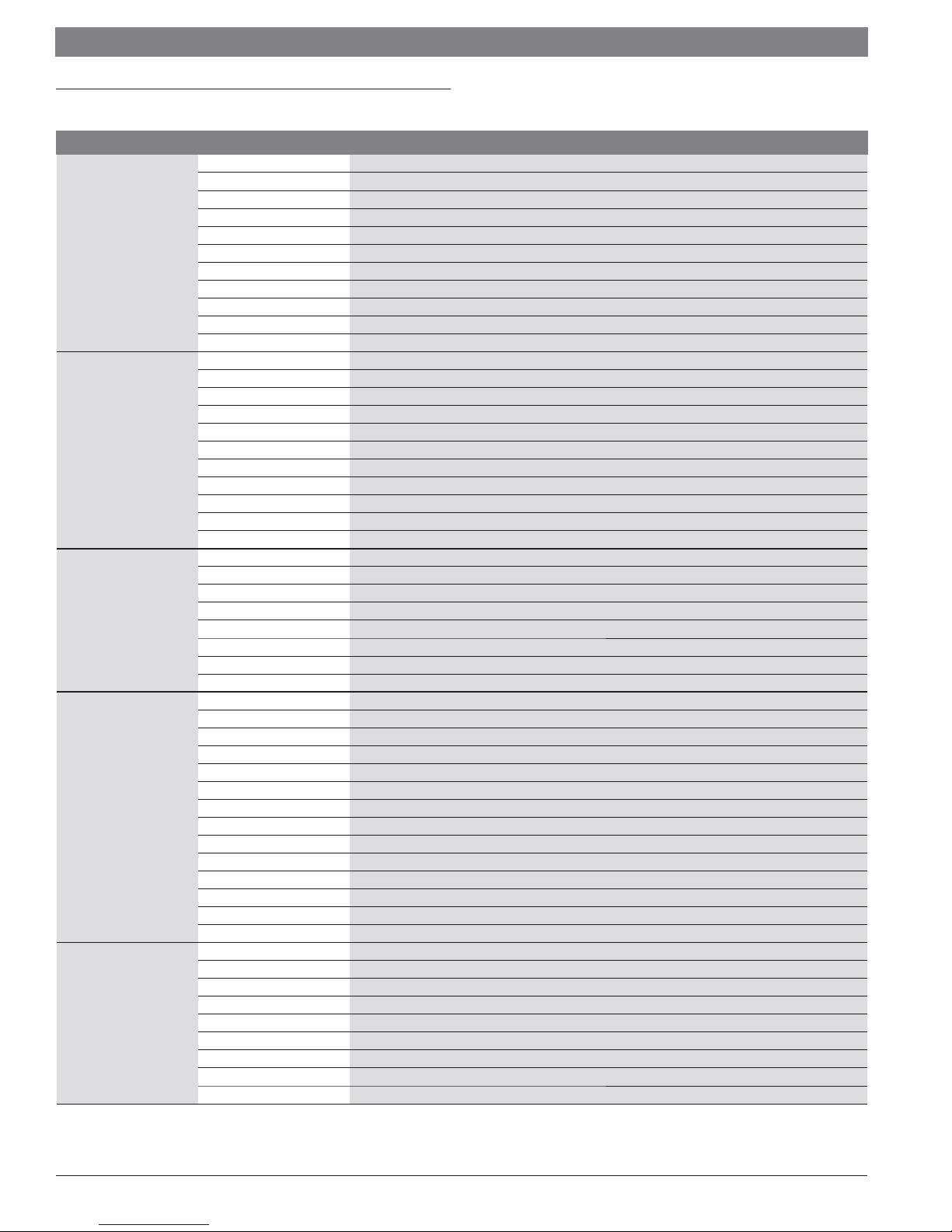
2 Boiler Settings Menu
Function Parameter Description
1 Central Heating (CH) Mode
2 Pump Mode
3 CH Setpoint
4 System Pump Overrun
5 Boiler Pump Overrun
General Operation
Outdoor Reset Curve
Domestic Hot Water
Cascade Operation
Start-up & Commisioning
Table 1
7 Central Heating Hysteresis (Diff erential)
9 Anti Cycle Period
10 Anti Cycle Temperature Diff erential
11 Ramp Delay Step Modulation
14 Maximum Power Central Heating
15 Minimum Power Central Heating / DHW
19 Design Supply Temperature
20 Design Outdoor Temperature
21 Baseline Supply Temperature
22 Baseline Outdoor Temperature
23 Design Supply Minimum Limit
24 Design Supply Maximum Limit
25 Warm Weather Shutdown
26 Boost Temperature Increment
27 Boost Time Delay
28 Night Setback Temperature
29 Weather Setpoint
35 Domestic Hot Water Mode
36 Domestic Hot Water Tank Diff erential DOWN
37 Domestic Hot Water Tank Diff erential UP
38 Domestic Hot Water Tank Supply Extra
42 Domestic Hot Water Priority
43 Domestic Hot Water Priority Time
44 Domestic Hot Water Pump Overrun
48 Domestic Hot Water Tank Setpoint
72 Permit Emergency Mode
73 Boiler Address
74 Emergency Setpoint
75 Delay Period Start Next Boiler
76 Delay Period Stop Next Boiler
77 Diff erential DOWN Start Boiler
78 Diff erential UP Stop Boiler
79 Maximum Setpoint Off set DOWN
80 Maximum Setpoint Off set UP
81 Start Modulation Delay Factor
82 Next Boiler START Rate
83 Next Boiler STOP Rate
84 Boiler Rotation Intervale
85 Domestic Hot Water Boiler Assign
89 Frost Protection
90 Frost Protection Setpoint
91 Domestic Hot Water Maximum Limit
92 Fan Speed Maximum
93 Fan Speed Minimum
94 Fan Speed Ignition
97 Appliance Model
98 Gas Type
99 Flue Length Range
Bosch Thermotechnology Corp. | 03.2018
Data subject to change
|
6
Bosch Buderus SSB255 | SSB399 | SSB512 Boilers Control Operations Guide
3 Heating Modes
3.1 Central heating (CH) mode
There are 6 onboard CH Mode settings which may be selected with the SSB Boiler.
1. CH Mode = “0” [default mode] Setpoint control of the boiler using dry
contacts (TT)
2. CH Mode = “1” Outdoor Reset using ON/OFF control of the boiler using dry
contacts (TT)
3. CH Mode = “2” Full Outdoor reset with no heat demand
4. CH Mode = “3” Permanent Setpoint Demand
5. CH Mode = “4” Analog control (0-10Vdc) of set point temperature
6. CH Mode = “5” Analog control (0-10Vdc) of Boiler Power (%)
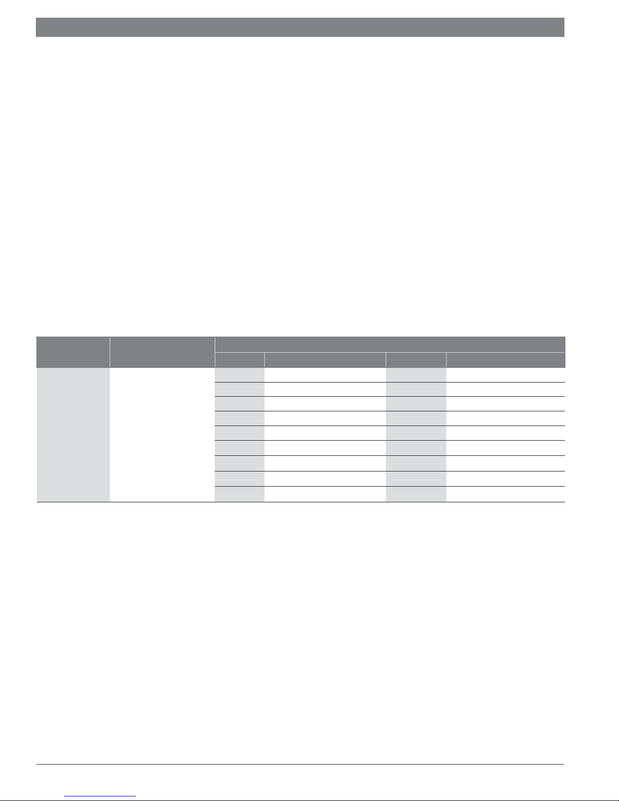
Central Heating Mode 0 [default mode]
(Setpoint control of the boiler using dry contacts #11 and #12)
CH Mode “0” - Boiler demand is generated thru a call for heat on low voltage contacts
#11 and #12 (dry contacts only). The Boiler will then target a temperature equal to
“CH Setpoint” (par.#3) at the Supply Temperature Sensor. If Temperature exceeds
the target Setpoint temperature by “CH Hysteresis” (par.#7) the burner will shut off
until the Supply Temperature Sensor drops the value of “CH Hysteresis” below the
target Setpoint Temperature.
Example:
If “CH Setpoint” is set for 140°F and CH Hysteresis is set for 10°F and there is a call
for heat on #11 and #12 the burner will start when the Boiler Supply Temperature
(System Supply Temperature sensor for cascade) reads a temperture of 130°F or less
and will remain operating until the call for heat is satisifi ed or until the sensor reads
a temperature of 150°F or greater. As long as the call for heat remains the Boiler and
CH Pump contacts will remain energized. The Burner will remain off until temperature
falls to 130°F.
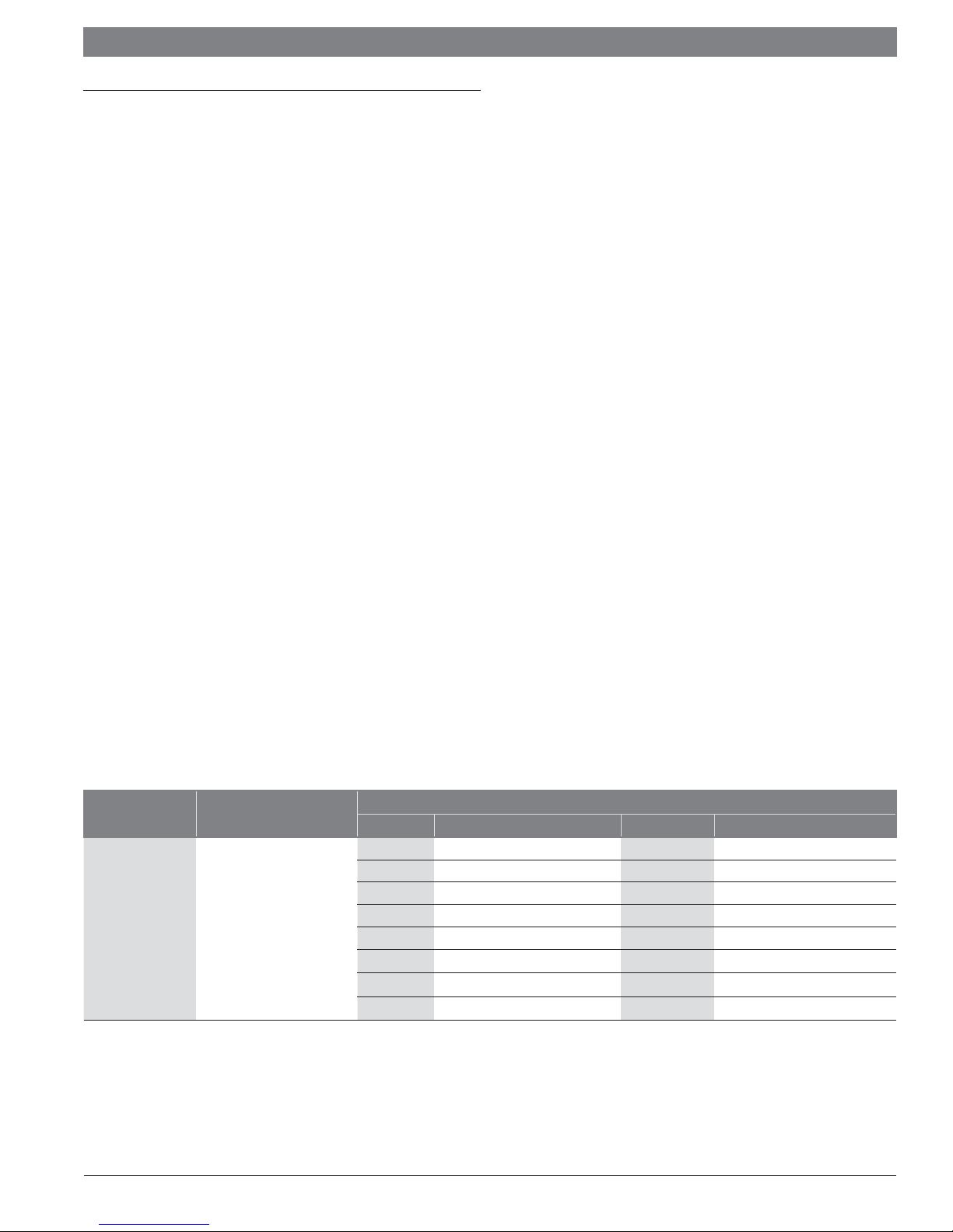
Central Heating
(CH) Mode
CH Mode = “0”
Table 2
Description
Setpoint control using dry
contacts (TT)
Parameter # Description Default Range
3 CH Setpoint 176°F 68 - 194°F
4 System pump overrun 300 sec. 0 – 900 sec.
5 Boiler pump overrun 300 sec. 0 – 900 sec.
7 CH Hysteresis 5.4°F 0 - 36°F
9 Anti-cycle period 180 sec. 10 – 900 sec.
10 Anti-cycle Temp Diff 12.6°F 0 - 36°F
23 Design Supply Min 68°F 39.2 – 179.6°F
24 Design Supply Max. 194°F 80.6 - 194°F
Set these Parameters
Data subject to change
03.2018 | Bosch Thermotechnology Corp.
Control Operations Guide Bosch Buderus SSB255 | SSB399 | SSB512 Boilers | 7
Central Heating Mode 1
(On/Off with Outdoor Reset using dry contacts #11 and #12)
CH Mode “1” - Boiler demand is generated thru a call for heat on low voltage
contacts #11 and #12 (dry contacts only). Boiler will target a system supply water
temperature equal to the corresponding point on the installer programmed heating
curve. (See page 7 for details on how-to program the heating curve). If the System
Temperature sensor exceeds the calculated heating curve temperature by “CH
Hysteresis” (par.#7) the burner will shut off until the System Temperature sensor
reads “CH Hysteresis” below the target Setpoint Temperature.
Example:
Based on the heating curve programmed by the installer, the calculated supply water
temperature on a 32°F degree day outside corresponds with a target boiler water
temperature of 140°F. If CH Hysteresis is set for 10°F, and there is a call for heat
on #11 and #12, then the burner will turn on when the Boiler Supply Temperature
sensor (System Supply Temperature sensor for cascade) reads a temperture of
130°F or less and will remain operating until the call for heat is satisifi ed or until the
sensor reads a temperature of 150°F or greater. As long as the call for heat remains
the Boiler and CH Pump contacts will remain energized. The Burner will remain off
until temperature measured at the system supply sensor falls to 130°F
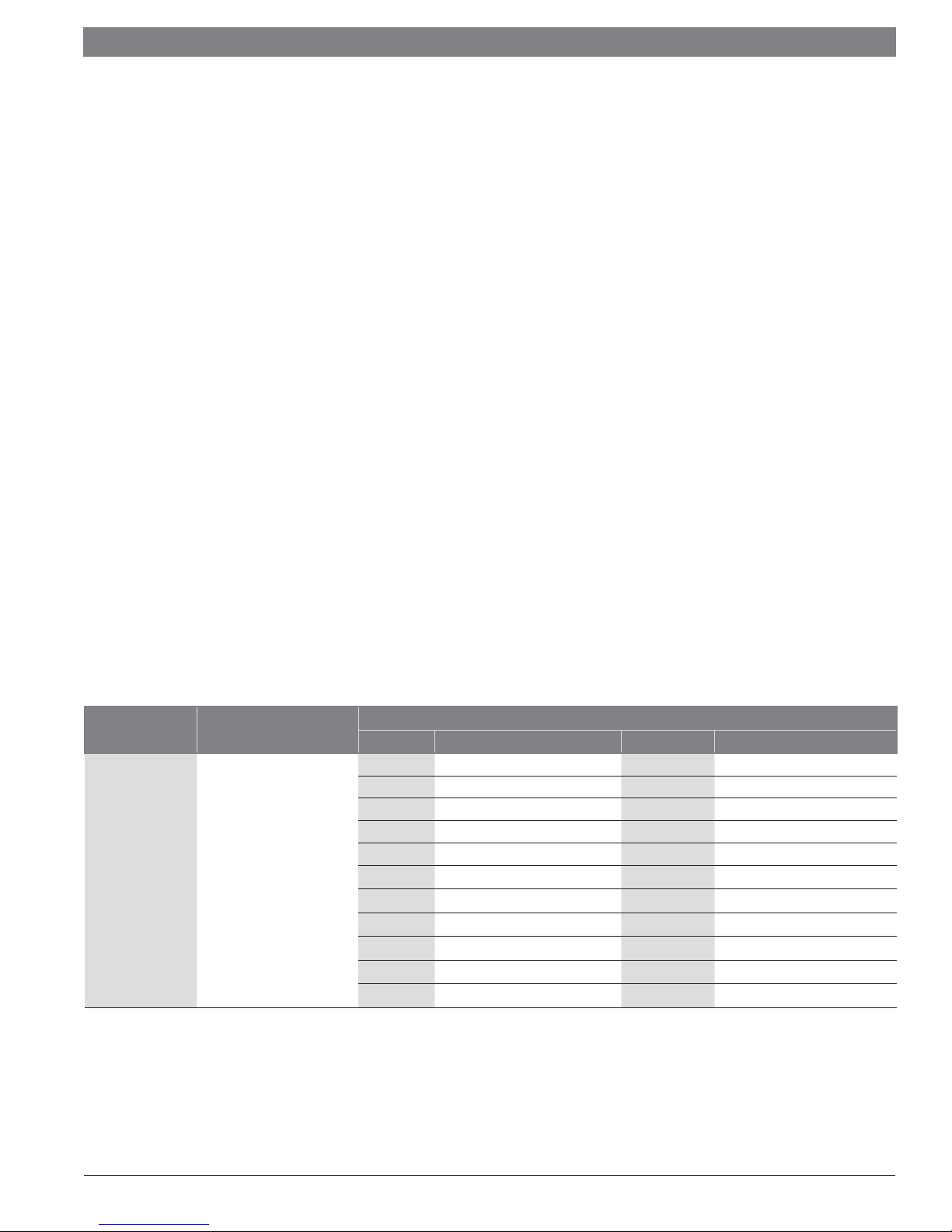
Central Heating
(CH) Mode
CH Mode = “1”
Table 3
Description
On/Off with reset water
temperature
Set these Parameters
Parameter # Description Default Range
19 Design Supply °F 176°F 68 - 194°F
20 Design Outdoor °F 24.8°F -13 - 77°F
21 Baseline Supply °F 104°F 68 - 194°F
22 Baseline Outdoor °F 69.8°F 35.6 - 86°F
23 Design Supply min 68°F 39.2 – 179.6°F
24 Design Supply max 194°F 80.6 - 194°F
25 WWSD 69.8°F 35.6 - 95°F
26 Boost Temp Incr. 0°F 0 - 54°F
27 Boost Temp Delay 20 min. 1 – 120 min.
Bosch Thermotechnology Corp. | 03.2018
Data subject to change
|
8
Bosch Buderus SSB255 | SSB399 | SSB512 Boilers Control Operations Guide
Central Heating Mode 2
(Full Outdoor reset with no heat demand)
CH Mode“2” - Boiler demand is generated when the outdoor temperature falls
below the value of “Weather Setpoint” (par.#29). When this occurs the Boiler and
CH pump contacts are energized and the Boiler will target a system supply water
temperature corresponding to a point on the installer programmed heating curve.
(See “How to Program the Heating Curve” for details). If the System Temperature
sensor exceeds the calculated heating curve temperature by “CH Hysteresis”
(par.#7) the burner will shut off until the System Temperature sensor reads “CH
Hysteresis” below the target Setpoint Temperature. This CH Mode is for constant
circulation applications. The Boiler and CH pump contacts will remain energized
as long as the outdoor temperature is less than the value of “Weather Setpoint”
(par.#29). Using the low voltage contacts #11 and #12 it is possible to apply a
set-back to the heating curve. “Night Setback Dif” (par.# 28) controls the parallel
temperature shift that is applied to the curve when #11 and #12 contacts are
“closed” using a clock or switch.
Example:
“Weather Setpoint” is programmed for 60°F. The outdoor temperature falls below
this value. The boiler energizes Boiler and CH pump contacts. Based on the heating
curve programmed by the installer in this application, the calculated supply water
temperature on this particular temperature day corresponds to a target boiler
water temperature of 140°F. If CH Hysteresis is set for 10°F, and and the outdoor
temperature remains below the value of “Weather Setpoint”, then the burner will turn
on when the Boiler Supply Temperature sensor (System Supply Temperature sensor
for cascade) reads a temperature of 130°F or less and will remain operating until
the outdoor temperature exceeds the value of “Weather Setpoint” or if the sensor
reads a temperature of 150°F or greater. As long as the outdoor temperature remains
below the value of “Weather Setpoint” the Boiler and CH Pump contacts will remain
energized. The burner will remain off until the system supply temperature falls to
130°F.
Central Heating
(CH) Mode
CH Mode = “2”
Table 4
Description
Full Outdoor reset
with no heat demand
Set these Parameters
Parameter # Description Default Range
19 Design Supply °F 176°F 68 - 194°F
20 Design Outdoor °F 24.8°F -13 - 77°F
21 Baseline Supply °F 104°F 68 - 194°F
22 Baseline Outdoor °F 69.8°F 35.6 - 86°F
23 Design Supply min 68°F 39.2 – 179.6°F
24 Design Supply max 194°F 80.6 - 194°F
25 WWSD 69.8°F 35.6 - 95°F
26 Boost Temp Incr. 0°F 0 - 54°F
27 Boost Temp Delay 20 min. 1 – 120 min.
28 Night Setback 18°F 0 - 90°F
29 Weather Setpoint 68°F 32 - 122°F
Data subject to change
03.2018 | Bosch Thermotechnology Corp.
Control Operations Guide Bosch Buderus SSB255 | SSB399 | SSB512 Boilers | 9
Central Heating Mode 3
(Permanent set point demand)
CH Mode“3” - Boiler demand is always “ON” in CH Mode 3 – “Permanent Demand
Mode”. In this mode the Boiler and CH Pump contacts will always be energized. When
the Supply Temperature Sensor falls below the value of “CH Setpoint” (par.#3)
minus the value of “CH Hysteresis” (par.#7), the burner will turn on. The burner
will remain on as long as the supply temperature remains below the value of “CH
Setpoint” plus “CH Hysteresis”. Using the low voltage contacts #11 and #12 it is
possible to apply a set-back to the “CH Setpoint” target temperature. “Night Setback
Dif” (par.# 28) controls the temperature shift that is applied to the “CH Setpoint”
when #11 and #12 contacts are “closed” using a clock or switch.
Example:
With both Boiler and CH Pump contacts energized, the boiler will monitor the Supply
Temperature Sensor. The application calls for a setpoint of 140°F with and Hysteresis
setting of 10°F. When the temperature of the Boiler Supply Temperature sensor
(System Supply Temperature sensor for cascade) falls below 130°F ( the value of
“CH Setpoint” minus “CH Hysteresis”) the burners will turn on. Burners will remain
on as long as the sensor does not exceed 150°F ( the value of “CH Setpoint” plus
“CH Hysteresis”). In the evening the application calls for a reduced supply water
temperature of 120°F. A timer/clock is installed and wired to contacts #11 and #12
of the boiler and these contacts are “closed” between the hours of 10 pm and 5 am.
During that time period the “CH Setpoint” is reduced by the value programmed into
“Night Setback Dif”. In this example the value is set for 20°F.
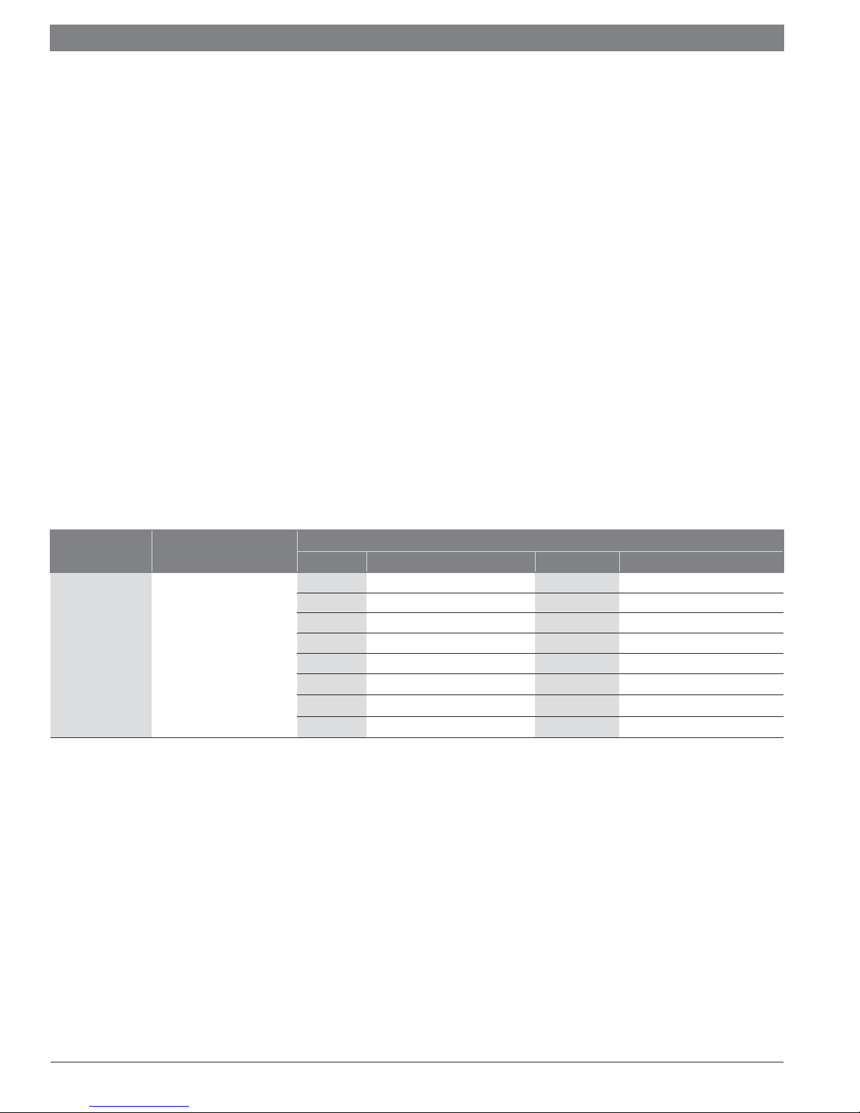
Central Heating
(CH) Mode
CH Mode = “3”
Table 5
Description
Permanent
Setpoint
Demand
Set these Parameters
Parameter # Description Default Range
3 CH Setpoint 176°F 68 - 194°F
4 System pump overrun 300 sec. 0 – 900 sec.
5 Boiler pump overrun 300 sec. 0 – 900 sec.
7 CH Hysteresis 5.4°F
9 Anti-cycle period 180 sec. 10 – 900 sec.
10 Anti-cycle Temp Diff 12.6°F 0 - 36°F
24 Setpoint Max. 194°F 80.6 - 194°F
28 Night Setback 18°F 0 - 90°F
Bosch Thermotechnology Corp. | 03.2018
Data subject to change
 Loading...