

Bosch Buderus SB625WS, Buderus SB745WS Installation Instructions Manual
Read these instructions carefully before installation and operation of the heating system.
Installation Instructions
Stainless Steel Condensing Boiler
Buderus SB625WS/Buderus SB745WS
6 720 805 220-00.1T
DANGER!
The installation instructions included in this Manual are intended solely for
use by a trained and certified installer, service company or the gas supply
company. If the information in this manual is not followed, a fire or explosion
may result causing property damage, personal injury, or death.
Have installation and service performed by a trained and certified
installer or service company, or the gas supply company.
Bosch recommends signing a service and maintenance contract with a
trained and certified installer or service company that covers annual
servicing and condition-based maintenance. Proper maintenance is a
fundamental requirement for safe and efficient operation and long
service life.
The boiler must be serviced annually including the main burner, ignition
burner, the entire venting system, and the combustion air supply. All
parts that show any signs of damage or corrosion must be replaced.
Improper installation, adjustment, alteration, service, or maintenance
can cause property damage, personal injury, or death. Refer to this
manual and consult a trained and certified installer or service company,
or the gas supply company before installation, service or maintenance.
The owner and operator is responsible for the operational safety and
regulatory compliance of the heating system.
THIS MANUAL SHOULD BE HANDED TO THE OWNER AND OPERATOR OF
THE APPLIANCE.
INSTALLER MUST REVIEW ALL SAFETY INSTRUCTIONS WITH THE
OWNER AND OPERATOR.
UPON COMPLETION OF THE INSTALLATION THE INSTALLER MUST
INSTRUCT THE OWNER AND OPERATOR ON THE FUNCTIONALITY AND
THE PROPER OPERATION OF THE BOILER AND THE HEATING SYSTEM
Low temperature condensing boilers for gas/oil fired power burners
6 720 805 218 (2013/02) en-us

2 | Contents
SB625WS/SB745WS6 720 805 218 (2013/02)
Contents
1 Key to symbols and safety instructions . . . . . . . . . . . . . . . . . . 3
1.1 Explanation of symbols . . . . . . . . . . . . . . . . . . . . . . . . . . 3
1.2 General safety instructions . . . . . . . . . . . . . . . . . . . . . . . 3
2 Product Description . . . . . . . . . . . . . . . . . . . . . . . . . . . . . . . . . . . 5
2.1 Intended use . . . . . . . . . . . . . . . . . . . . . . . . . . . . . . . . . . . 6
2.2 Certification and testing mark . . . . . . . . . . . . . . . . . . . . . 6
2.3 Regulations and Guidelines . . . . . . . . . . . . . . . . . . . . . . . 6
2.3.1 National regulation . . . . . . . . . . . . . . . . . . . . . . . . . . . . . . 6
2.3.2 Compliance with standards and regulations . . . . . . . . . . 6
2.3.3 Additional regulations for installations in the
Commonwealth of Massachusetts . . . . . . . . . . . . . . . . . 6
2.4 Suitable fuels . . . . . . . . . . . . . . . . . . . . . . . . . . . . . . . . . . 7
2.5 Scope of delivery . . . . . . . . . . . . . . . . . . . . . . . . . . . . . . . 8
2.6 Accessories . . . . . . . . . . . . . . . . . . . . . . . . . . . . . . . . . . . . 8
2.7 Tools, materials and auxiliary equipment . . . . . . . . . . . . 8
2.8 Data plate . . . . . . . . . . . . . . . . . . . . . . . . . . . . . . . . . . . . . 8
2.9 Dimensions and specifications . . . . . . . . . . . . . . . . . . . . 9
2.9.1 Dimensions . . . . . . . . . . . . . . . . . . . . . . . . . . . . . . . . . . . . 9
2.9.2 Technical Data . . . . . . . . . . . . . . . . . . . . . . . . . . . . . . . . 10
2.9.3 Water connections . . . . . . . . . . . . . . . . . . . . . . . . . . . . . 11
3 Water treatment . . . . . . . . . . . . . . . . . . . . . . . . . . . . . . . . . . . . . 13
3.1 Chemical and physical characteristics . . . . . . . . . . . . . 13
3.2 Central heating system . . . . . . . . . . . . . . . . . . . . . . . . . 13
3.2.1 Limescale deposits . . . . . . . . . . . . . . . . . . . . . . . . . . . . . 13
3.2.2 Deposit corrosion . . . . . . . . . . . . . . . . . . . . . . . . . . . . . . 14
3.2.3 Stray current corrosion . . . . . . . . . . . . . . . . . . . . . . . . . 14
3.2.4 Diffused and localized acid corrosion . . . . . . . . . . . . . . 14
3.3 New central heating systems . . . . . . . . . . . . . . . . . . . . . 14
3.4 Reconditioning old heating systems . . . . . . . . . . . . . . . 14
3.5 Elimination air and gas from central heating system . . 14
3.6 Use of Antifreeze . . . . . . . . . . . . . . . . . . . . . . . . . . . . . . 15
4 Transport . . . . . . . . . . . . . . . . . . . . . . . . . . . . . . . . . . . . . . . . . . . 16
5 Installation . . . . . . . . . . . . . . . . . . . . . . . . . . . . . . . . . . . . . . . . . . 17
5.1 Boiler Clearances . . . . . . . . . . . . . . . . . . . . . . . . . . . . . . 17
5.2 Assembling the paneling . . . . . . . . . . . . . . . . . . . . . . . . 18
5.3 Refitting the door hinges . . . . . . . . . . . . . . . . . . . . . . . . 20
5.3.1 Changing the direction of door opening . . . . . . . . . . . . 20
5.3.2 Removing the hinge assembly “B” . . . . . . . . . . . . . . . . . 23
5.4 Burners . . . . . . . . . . . . . . . . . . . . . . . . . . . . . . . . . . . . . . 23
5.5 Combustion gas exhaust . . . . . . . . . . . . . . . . . . . . . . . . 24
5.6 Venting Requirements . . . . . . . . . . . . . . . . . . . . . . . . . . 25
5.7 Code Required Vent Terminations . . . . . . . . . . . . . . . . 25
5.8 Combustion Air from outside the building . . . . . . . . . . 25
5.9 Combustion Air from an adjacent room . . . . . . . . . . . . 26
5.10 Condensate Removal . . . . . . . . . . . . . . . . . . . . . . . . . . . 26
5.11 Condensate . . . . . . . . . . . . . . . . . . . . . . . . . . . . . . . . . . . 26
5.11.1 Draining the condensate . . . . . . . . . . . . . . . . . . . . . . . . 26
5.11.2 Neutralizing the condensate . . . . . . . . . . . . . . . . . . . . . 26
6 Commissioning . . . . . . . . . . . . . . . . . . . . . . . . . . . . . . . . . . . . . . 28
6.1 Control unit settings . . . . . . . . . . . . . . . . . . . . . . . . . . . . 28
6.2 Hydraulic connection to the heating system . . . . . . . . 29
6.3 Hydraulic flow through boiler . . . . . . . . . . . . . . . . . . . . 29
6.4 Making the electrical connection . . . . . . . . . . . . . . . . . 30
6.5 Fitting temperature sensors . . . . . . . . . . . . . . . . . . . . . 31
6.6 Flushing the heating system . . . . . . . . . . . . . . . . . . . . . 31
6.7 Filling the heating system . . . . . . . . . . . . . . . . . . . . . . . 32
6.8 Preparing the heating system for operation . . . . . . . . . 32
6.9 Commissioning the control unit and burner . . . . . . . . . 32
6.10 Setting control unit parameters . . . . . . . . . . . . . . . . . . 32
6.11 Commissioning report . . . . . . . . . . . . . . . . . . . . . . . . . . 33
7 Shutting down . . . . . . . . . . . . . . . . . . . . . . . . . . . . . . . . . . . . . . . 34
7.1 Shutting down the heating system . . . . . . . . . . . . . . . . 34
7.2 Shutting down the heating system in an emergency . . 34
8 Inspection and maintenance . . . . . . . . . . . . . . . . . . . . . . . . . . 35
8.1 Why is regular maintenance important? . . . . . . . . . . . . 35
8.2 Maintenance . . . . . . . . . . . . . . . . . . . . . . . . . . . . . . . . . . 35
8.2.1 Opening the door . . . . . . . . . . . . . . . . . . . . . . . . . . . . . . 35
8.2.2 Adjusting the door . . . . . . . . . . . . . . . . . . . . . . . . . . . . . 35
8.3 Cleaning the boiler . . . . . . . . . . . . . . . . . . . . . . . . . . . . . 36
8.4 Checking and correcting the water pressure . . . . . . . . 37
8.4.1 When should you check the water pressure in the
heating system? . . . . . . . . . . . . . . . . . . . . . . . . . . . . . . . 37
8.4.2 Sealed unvented systems . . . . . . . . . . . . . . . . . . . . . . . 37
8.5 Inspection and maintenance reports . . . . . . . . . . . . . . 38
9 Spare parts . . . . . . . . . . . . . . . . . . . . . . . . . . . . . . . . . . . . . . . . . 40
10 Troubleshooting . . . . . . . . . . . . . . . . . . . . . . . . . . . . . . . . . . . . . 47
11 Environmental protection/disposal . . . . . . . . . . . . . . . . . . . . 48
12 Glossary . . . . . . . . . . . . . . . . . . . . . . . . . . . . . . . . . . . . . . . . . . . . 49
Key to symbols and safety instructions | 3
6 720 805 218 (2013/02)SB625WS/SB745WS
1 Key to symbols and safety instructions
1.1 Explanation of symbols
Warnings
Keywords at the start of a warning indicate the type and seriousness of
the ensuing risk if measures to prevent the risk are not taken.
The following keywords are defined and can be used in this document:
• NOTE indicates that property damage may occur.
• CAUTION indicates that personal injury may occur.
• WARNING indicates that severe personal injury may occur.
• DANGER indicates that severe personal injury or death may occur.
Important information
Additional symbols
1.2 General safety instructions
If you hear gas leaking
▶ Leave the building immediately.
▶ Prevent others from entering the building.
▶ Notify the police and fire department from outside the building.
▶ From outside the building, call the gas supply company and a trained
and certified installer or service company.
If you smell gas
▶ Turn off the gas shut-off valve.
▶ Open windows and doors
▶ Do not touch any electrical switch, telephone, and do not use outlets.
▶ Extinguish all open flames.
▶Do not smoke!
▶ Do not use lighters!
▶ Warn all occupants of the building that they need to leave the building.
▶ Do not ring doorbells!
▶ Notify the police and fire department from outside the building.
▶ From outside the building, call the gas supply company and a trained
and certified installer or service company.
If you smell flue gas
▶ Switch off the heating system by shutting off the emergency shut-off
switch.
▶ Open windows and doors.
▶ Call a trained and certified installer or service company.
DANGER: Risk of fatal injury from failing to consider your own
safety!
▶ Never risk your own life. Your own safety must always take the highest
priority
NOTICE: Risk of appliance damage from improper operation of the
boiler!
▶ Only use the boiler for its intended purpose.
▶ Only operate the boiler if it has been installed and maintained per the
instructions provided in the Installation Manual.
▶ Do not attempt to operate an appliance if any part of it is not in
working order or is damaged.
▶ Use only original spare parts! The use of parts not supplied by the
manufacturer may cause damage to the boiler, other property and
personal injury. Also, boiler damage caused by the use of
unauthorized parts is not covered by the warranty.
DANGER: Risk of fire when soldering and brazing!
▶ Take appropriate protective measures when soldering and brazing
around combustible and flammable material.
NOTICE:
▶ The installation must comply with all applicable national, state, and
local codes, rules, and regulations.
▶ The operator is responsible for the operational safety and regulatory
compliance of the heating system.
▶ In the Commonwealth of Massachusetts, the appliance must be
installed by a licensed plumber or gas fitter.
DANGER: Risk of personal injury or death from flue gas poisoning!
▶ Do not install a thermostatic flue gas damper downstream of the draft
hood.
▶ Do not tamper with, remove, or attempt to repair the blocked vent
switch.
▶ When replacing the blocked vent switch, install the new part in the
original location.
▶ A blocked vent switch tripping more than once indicates a problem
with the venting system or chimney which must be repaired
immediately.
▶ Ensure none of the vent pipes and chimneys are damaged or blocked.
▶ Connect only one appliance to each venting system or chimney.
▶ The venting system must not feed into or route through another air
extraction duct.
▶ The venting system must be inspected annually. All parts that show
any signs of damage or corrosion must be replaced.
▶ Never close off or reduce the size of the combustion air openings.
▶ The boiler must not be operated until any obstructions have been
removed.
Warnings in this document are identified by a warning
triangle printed against a grey background.
Important information for the proper use of the boiler is
also provided in this manual. You will find the
information with a symbol shown on the left and
bordered by horizontal lines above and below the text.
Symbol Meaning
▶ Sequence of steps
Cross-reference to other points in this document or to
other documents
• Listing/list entry
– Listing/list entry (2nd level)
Table 1

4 | Key to symbols and safety instructions
SB625WS/SB745WS6 720 805 218 (2013/02)
DANGER: Risk of personal injury or death from explosion!
▶ Work on gas components may only be carried out by a trained and
certified installer or service company.
▶ Appliance installation, the connection of gas and vent piping, initial
commissioning, electrical connections, and service and maintenance
must only be carried out by a trained and certified installer or service
company.
DANGER: Risk of personal injury or death from fire!
▶ Do not use flammable or combustible material in the boiler room.
▶ It is recommended not to store any items within 16 inches (415mm)
of the appliance
CAUTION: Appliance damage from contaminated combustion air!
▶ Keep the combustion air free of corrosive substances, e.g.
halogenated hydrocarbons from painting operations or beauty
salons.
▶ Keep combustion air free from dust and lint, e.g. from laundry or
agricultural operations.
▶ If clean room air is not available, fresh outdoor combustion air must be
provided
DANGER: Risk of personal injury or death from electric shock.
▶ Before removing the front panel, disconnect the heating system from
the electrical power supply by shutting off the emergency shutoff
switch or the heating system circuit breaker.
▶ It is not enough to switch off the control panel. Power to the panel
must be disconnected! Ensure that the power is not restored
unintentionally by following proper lock out/tag out procedures.
▶ Only qualified electricians are permitted to carry out electrical work.
DANGER: Safety devices!
▶ Never shut off safety valves!
▶ Hot water may escape from the safety valve at any time when the
appliance is running.
DANGER: Risk of personal injury or death after a flood!
▶ Do not attempt to operate an appliance if any part of it has been under
water.
▶ An appliance that was subject to flooding must be replaced.
NOTICE:
▶ Upon completion of the installation, these instructions should be
handed to the owner and operator of the appliance.
▶ The installer must instruct the owner and operator on the functionality
of the components and the proper operation of the boiler and the
heating system.
▶ The boiler must be serviced annually including the main burner,
ignition burner, the entire venting system, and the combustion air
supply. All parts that show any signs of damage or corrosion must be
replaced.
Product Description | 5
6 720 805 218 (2013/02)SB625WS/SB745WS
2 Product Description
The high efficiency SB Series boilers are designed to condense flue
gases through a unique three-pass construction for installation in a
mechanical room. While they are designed primarily for central heating
purposes, in conjunction with a suitable storage tank they can also be
used to produce domestic hot water.
All parts that come into contact with the combustion gases are made
from titanium stabilized stainless steel to ensure maximum resistance to
the corrosive action of acid condensation.
The boiler has been designed with the combustion chamber at the top
and the smooth pipe tube bundle at the bottom to optimize heat
exchange and to maximize the condensing effect.
The boiler has a high total water content which is differentially
distributed between its top and bottom sections. This hydraulic feature
allows outgoing water to reach the set temperature quickly while
maintaining the condensing effect and the water heating time around the
tube bundle for as long as possible.
The boilers feature lightly pressurized combustion chambers for a
smoother burner action, and high temperature resistant, stainless steel
turbulators inside the tube bundle for maximum burner efficiency.
The boiler body is thoroughly insulated with a layer of high density glass
wool.
The paint finished external paneling is also internally insulated with a
layer of high density glass wool.
The boiler’s front door and the flue gas chamber can be opened
completely to facilitate the inspection, maintenance and cleaning of
internal parts and to speed up servicing in general.
The front door can open in either direction and can be opened without
removing the burner. The door is factory fitted with hinges on the left,
but these can be reversed if necessary to suit individual installations.
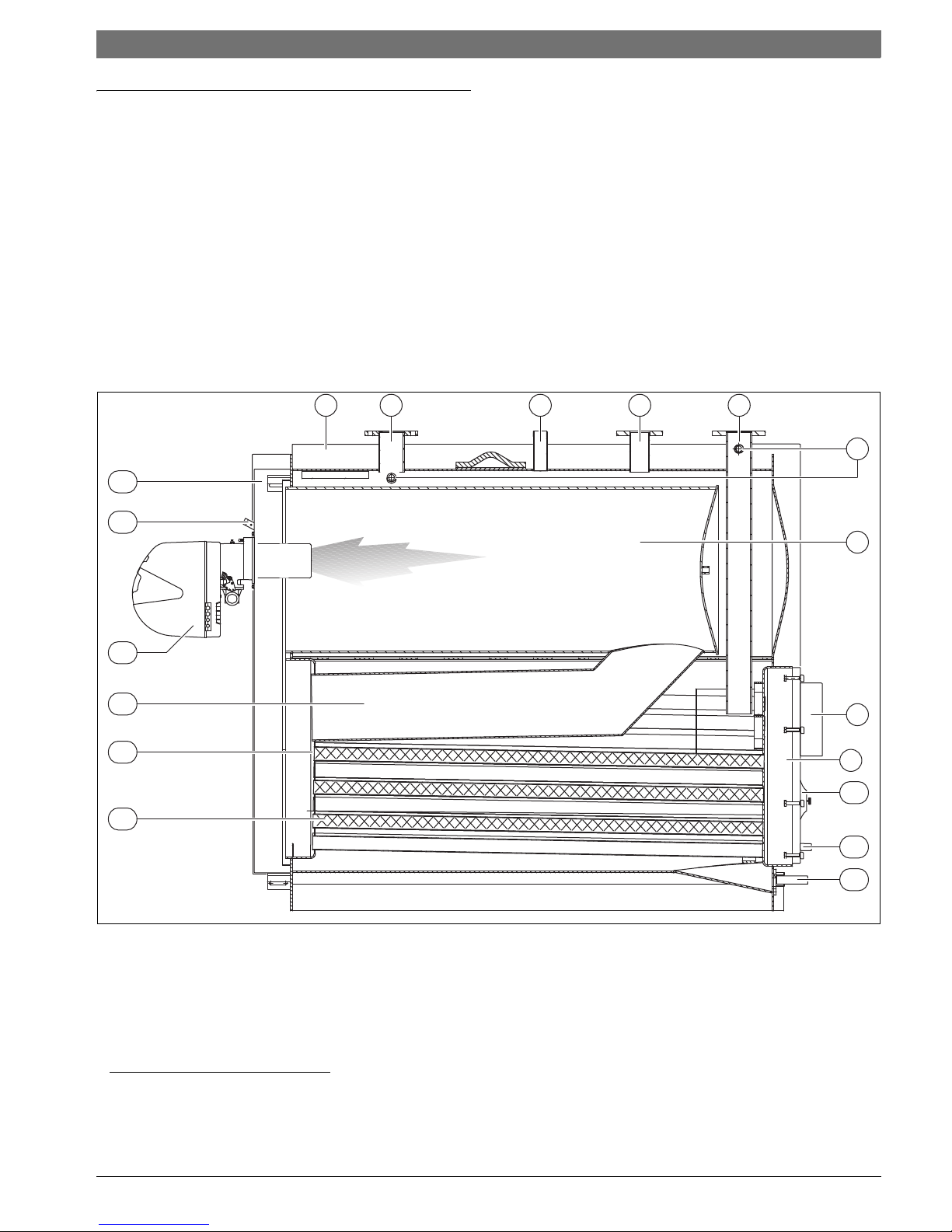
Fig. 1 Main components
[1] Paneling
[2] Heating flow outlet
[3] Safety device fitting
1)
[4] Heating return (high temperature)
[5] Heating return (low temperature)
2)
[6] Instrument for bulb/probe socket
[7] Combustion chamber
[8] Flue connection
[9] Flue gas box
[10] Inspection port
[11] Condensate drain
[12] Boiler drain
[13] Turbulators
[14] Flue pipes
[15] Second flue pass
[16] Burner
[17] Flame inspection window with pressure measurement point
[18] Door
1 2 3 4 5
6
7
8
9
10
11
12
13
14
15
17
18
16
6 720 805 218-01.1T
1) On the 1550WS model the low temperature heating return is located at the rear
of the boiler.
2) On the 745WS models (800-1550) the safety device fitting is flanged.
6 | Product Description
SB625WS/SB745WS6 720 805 218 (2013/02)
2.1 Intended use
This boiler must only be used for the purpose specified by the
manufacturer and for which it is designed.
The SB625WS/SB745WS can be operated with gas, oil, and
combination burners. For a list of the approved burners, please contact
Bosch Thermotechnology Corp.
The boiler can be operated with an aquastat, the Logamatic 4000, and
other control systems.
The manufacturer declines all responsibility, contractual or other, for
damage to property or injury to persons or animals caused by improper
installation, adjustment, maintenance or use.
2.2 Certification and testing mark
This appliance has been tested and certified and meets all applicable
standards for the US and Canadian markets:
• CSA-AM 3.1 Industrial and commercial gas-fired package boilers
• CSA B140.0 General requirements for oil burning equipment
• CSA B140.2.1-10 Atomizing-type oil burners
• CSA B140.7-05 Oil-burning equipment - steam and hot water boilers
• UL 296 Standard for oil burners
• UL 726 Standard for oil-fired boiler assemblies
• UL 795 Standard for commercial industrial gas heating equipment
2.3 Regulations and Guidelines
2.3.1 National regulation
The heating system must comply with the requirements of the relevant
regulatory authorities or otherwise of the National Fuel Gas Code, ANSI
Z 223.1 In Canada, the requirements of CAN/CGA-B.149.1 and 2, or
CAN/CGA-B.139 must be observed.
If specified by the relevant regulatory authorities, the heating system
must comply with the regulations of the Standard for Controls and
Safety Devices for Automatically Fired Boilers, ANSI/ASME CSD-1.
Carbon monoxide detectors must be installed as specified by the local
regulations. The boiler must be serviced annually.
2.3.2 Compliance with standards and regulations
Installation of the boiler must comply with all applicable codes and
regulations imposed by the national, Federal or local authorities and
bodies. If no specific requirements are defined, in the USA, the latest
edition of the National Fuel Gas Code ANSI Z223.1/NFPA 54 must be
complied with.
In Canada, installation must comply in all respects with the latest edition
of the Natural Gas and Propane Installation Code, CAN/CGA-B. 149, the
Installation Code for Oil Burning Equipment, CAN/CGA-B. 139 and the
applicable local regulations and requirements for the appliance
category. The relevant authorities and regulatory bodies must be
informed before installation starts.
Where required by local regulations, the system must comply with the
American Society of Mechanical Engineers Safety Code for Controls and
Safety Devices for Automatically Fired Boilers (ASME CSD-1).
The local regulations regarding minimum pressure detectors and lowwater safety cutouts must be observed. Installation and operation must
comply with the device manufacturer‘s technical documentation.
We recommend fitting an 80 mesh dirt filter externally to the boiler
return to prevent contamination of the boiler by the water source.
Leak test
A leak test must be carried out. The testing pressure is based on the
normal operating pressure of the heating system and should be 1.3
times that pressure, and in any case no less than 14 psi (1 bar).
Safety limits
2.3.3 Additional regulations for installations in the
Commonwealth of Massachusetts
(a) For all side wall horizontally vented gas fueled equipment installed in
every dwelling, building or structure used in whole or in part for
residential purposes, including those owned or operated by the
Commonwealth and where the side wall exhaust vent termination is less
than seven (7) feet above finished grade in the area of the venting,
including but not limited to decks and porches, the following
requirements shall be satisfied:
• INSTALLATION OF CARBON MONOXIDE DETECTORS. At the time of
installation of the side wall horizontal vented gas fueled equipment,
the installing plumber or gasfitter shall observe that a hard wired
carbon monoxide detector with an alarm and battery back-up is
installed on the floor level where the gas equipment is to be installed.
In addition, the installing plumber or gasfitter shall observe that a
battery operated or hard wired carbon monoxide detector with an
alarm is installed on each additional level of the dwelling, building or
structure served by the side wall horizontal vented gas fueled
equipment. It shall be the responsibility of the property owner to
WARNING: Risk of fatal Injury from explosion of
flammable gases!
▶ Installation, connection of the fuel supply and flue
pipe, commissioning, connection of the electrical
power supply, servicing and repair may only be
carried out by an authorized heating engineer.
▶ Any work on gas-carrying components may only be
carried out by an authorized gas installer.
The details on the boiler rating plate are definitive and
must be observed.
Safety limits
Maximum allowable temperature: 230 °F
(110 °C)
Maximum operating temperature 210 °F
(98.8 °C)
Permissible operating pressure: 80 psi
(5.5 bar)
Maximum cycle time for:
Safety temperature limiter: 40 s
Temperature control: 40 s
Table 2 Safety limits
Product Description | 7
6 720 805 218 (2013/02)SB625WS/SB745WS
secure the services of qualified licensed professionals for the
installation of hard wired carbon monoxide detectors.
– In the event that the side wall horizontally vented gas fueled
equipment is installed in a crawl space or an attic, the hard wired
carbon monoxide detector with alarm and battery back-up may be
installed on the next adjacent floor level.
– In the event that the requirements of this subdivision cannot be met
at the time of completion of installation, the owner shall have a
period of thirty (30) days to comply with the above requirements;
provided, however, that during said thirty (30) day period, a
battery operated carbon monoxide detector with an alarm shall be
installed.
• APPROVED CARBON MONOXIDE DETECTORS. Each carbon
monoxide detector as required in accordance with the above
provisions shall comply with NPA 720 and be ANSI/UL 2034 listed
and IAS certified.
• SIGNAGE. A metal or plastic identification plate shall be permanently
mounted to the exterior of the building at a minimum height of eight
(8) feet above grade directly in line with the exhaust vent terminal for
the horizontally vented gas fueled heating appliance or equipment.
The sign shall read, in print size no less than one-half (½) inch in size,
“GAS VENT DIRECTLY BELOW. KEEP CLEAR OF ALL
OBSTRUCTIONS”.
• INSPECTION. The state or local gas inspector of the side wall
horizontally vented gas fueled equipment shall not approve the
installation unless, upon inspections, the inspector observes carbon
monoxide detectors and signage installed in accordance with the
provisions of 248 CRM 5.08(2)(a) 1 through 4.
(b) EXEMPTIONS: The following equipment is exempt from 248 CRM
5.08(2)(a) 1 through 4:
• The equipment listed in Section 10 entitled “Equipment Not Required
To Be Vented” in the most current edition of NFPA 54 as adopted by
the board; and
• Product Approved side wall horizontally vented gas fueled equipment
installed in a room or structure separate from the dwelling, building or
structure used in whole or in part for residential purposes.
(c) MANUFACTURERS REQUIREMENTS - GAS EQUIPMENT VENTING
SYSTEM REQUIRED. When the manufacturer of Product Approved side
wall horizontally mounted gas equipment provides a venting system
design or venting system components with the equipment, the
instructions provided by the manufacturer for the installation of the
equipment and venting shall include:
• Detailed instructions for the installation of the venting system or the
venting system components; and
• A complete parts list for the venting system design or venting system.
(d) MANUFACTURERS REQUIREMENTS - GAS EQUIPMENT VENTING
SYSTEM NOT PROVIDED. When the manufacturer of Product Approved
side wall horizontally vented gas fueled equipment does not provide the
parts for the venting of flue gases, but identifies “special venting
systems”, the following requirements shall be satisfied by the
manufacturer:
• The referenced “special venting systems” shall be included with the
appliance or equipment installation instructions; and
• The “special venting systems” shall be Product Approved by the
Board, and the instructions for that system shall include a parts list
and detailed installation instructions.
(e) A copy of all instructions for all Product Approved side wall
horizontally vented gas fueled equipment, all venting instructions, all
parts lists for venting instructions, and/or venting design instructions
shall remain with the appliance or equipment at the completion of the
installation.
2.4 Suitable fuels
Permissible fuels
• Natural gas from the public gas supply in accordance with national
regulations with a total sulphur content < 15ppm.
• LP in accordance with national regulations with a content of
elementary sulphur < 1.5 ppm and volatile sulphur < 50 ppm.
• Ultra Low Sulphur Diesel in accordance with national regulations with
a content of elementary sulphur < 15 ppm (for use as back-up fuel in
condensing operation).
• Heating oil type 2 when boiler return temperature is not lower than
140 degrees Fahrenheit; non-condensing operation (for use as backup fuel only). See the warranty statement for additional details.
NOTICE:
▶ Do not use gasoline, crankcase drainings, or any oil
containing gasoline.
The boiler must only be operated with the specified
fuels.
Only burners that are suitable for the specified fuels may
be used.
Observe the manufacturer's burner selection list and the
burner manufacturer's instructions.
8 | Product Description
SB625WS/SB745WS6 720 805 218 (2013/02)
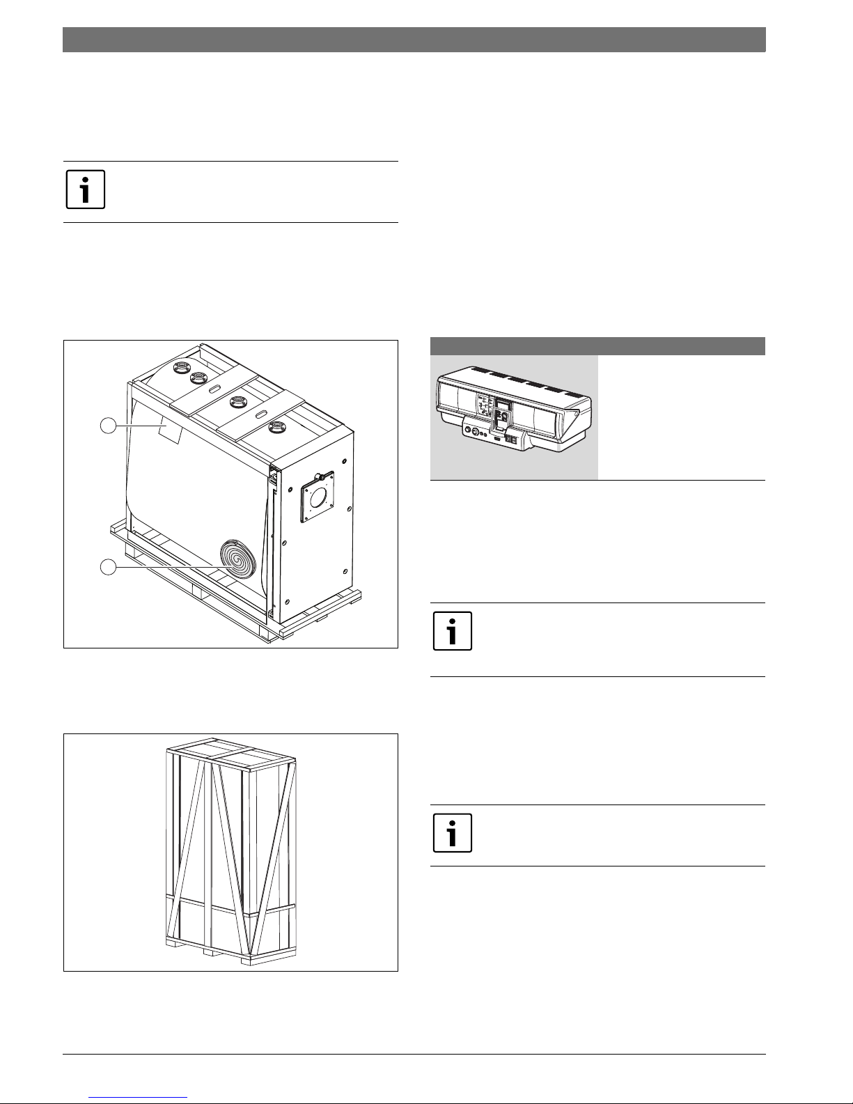
2.5 Scope of delivery
The boilers SB625WS / SB745WS comes in two separate crates and
one additional box.
Boiler body crate:
The boiler body crate bears the documentation envelope [1] and
contains:
• Instruction manual
• Certificate of Warranty
• Bar code labels
• Ceramic insulation [2]
Fig. 2 Boiler body crate
Paneling crate:
The paneling crate, complete with assembly accessories, protected by
cardboard packaging and a wooden crate.
Fig. 3 Paneling crate
Accessory box:
The boiler accessory box contains
• Manifold
• Pressure relief valve
• Pressure/temperature gauge
Checking the delivery for completeness
▶ After delivery, check all packaging is in perfect condition.
▶ Check the delivery for completeness.
▶ Dispose of packaging in an environmentally responsible manner.
2.6 Accessories
Control panels
The control panels listed below may be supplied by the manufacturer for
use with the SB625WS / SB745WS boilers.
2.7 Tools, materials and auxiliary equipment
For the installation and maintenance of the boiler, standard tools are
required, as used for heating, gas, water and electrical installations.
2.8 Data plate
Serial number plate
The serial number plate is located on the rear of the boiler block and
specifies the serial number and model.
Data plate
This lists the appliance’s technical specifications and performance. The
data plate will be factory installed on the boiler side panel.
The instruction manual is an integral part of the boiler.
Once located, read it thoroughly and keep it safe.
6 720 805 218-11.2T
1
2
6 720 805 218-12.1T
Model Description
The Logamatic 4321 control unit
is designed for low temperature
and condensing operation in
single or multiple boiler systems.
Additional possible functions
include DHW, mixed heating zones
and solar thermal integration.
Table 3 Control panels
If you contact the manufacturer with any questions about
this product, always provide the details on the data plate
and serial number plate. These details enable us to assist
you specifically and quickly.
If these plates or any other means of clearly identifying
the product are defaced, removed or lost, proper
installation and servicing may be difficult.
Product Description | 9
6 720 805 218 (2013/02)SB625WS/SB745WS
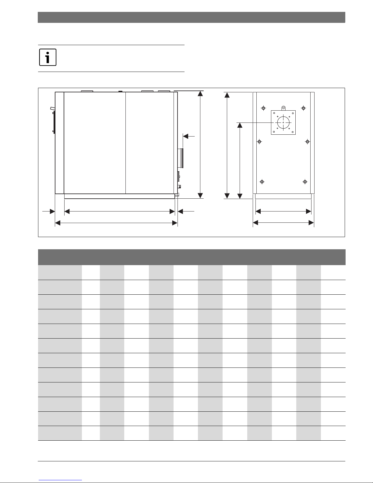
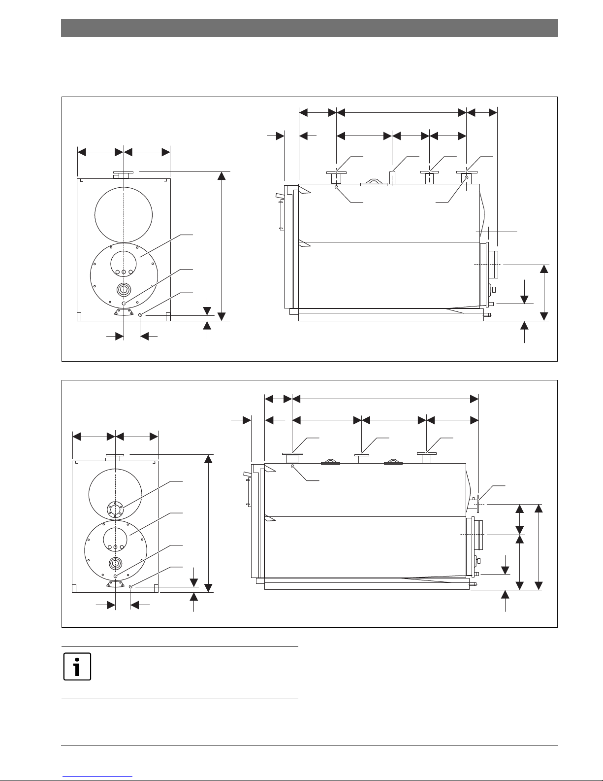
2.9 Dimensions and specifications
2.9.1 Dimensions
Fig. 4 Dimensions
Values obtained with RS.../M-burners.
AL1 E
L
D
H1
H
F
B
6 720 805 218-13.1T
C
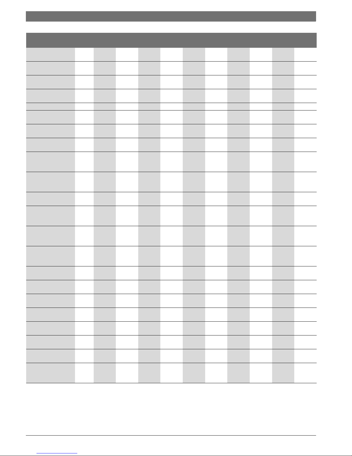
Description Unit SB625WS SB745WS
160 220 290 370 480 640 800 1050 1300 1550
A: Base width inch
(mm)
27 3/16
(690)
27 3/16
(690)
29 1/2
(750)
29 1/2
(750)
31 1/8
(790)
31 1/8
(790)
37 7/16
(950)
37 7/16
(950)
42 1/8
(1070)
44 1/2
(1130)
B: Overall width inch
(mm)
29 1/8
(740)
29 1/8
(740)
33 1/2
(850)
33 1/2
(850)
35 7/16
(900)
35 7/16
(900)
41 3/4
(1060)
41 3/4
(1060)
46 7/16
(1180)
48 1/4
(1225)
C: Length base to
front
inch
(mm)
4 3/4
(120)
4 3/4
(120)
4 3/4
(120)
4 3/4
(120)
4 3/4
(120)
4 3/4
(120)
4 3/4
(120)
4 3/4
(120)
4 3/4
(120)
4 3/4
(120)
D: Height of burner
plate
inch
(mm)
36 7/16
(925)
36 7/16
(925)
40 9/16
(1030)
40 9/16
(1030)
48 5/8
(1235)
48 5/8
(1235)
54 3/4
(1390)
54 3/4
(1390)
58 7/8
(1495)
62 5/8
(1590)
E: Length base to
rear
inch
(mm)
1 9/16
(40)
1 9/16
(40)
1 9/16
(40)
1 9/16
(40)
1 9/16
(40)
1 9/16
(40)
1 9/16
(40)
1 9/16
(40)
1 9/16
(40)
1 9/16
(40)
F: Flue connection
depth
inch
(mm)
2 3/4
(70)
2 3/4
(70)
2 3/4
(70)
2 3/4
(70)
2 3/4
(70)
2 3/4
(70)
2 3/4
(70)
2 3/4
(70)
2 3/4
(70)
2 3/4
(70)
H – Height o f water
fittings
inch
(mm)
52 3/4
(1340)
52 3/4
(1340)
57 1/16
(1450)
57 1/16
(1450)
66 3/4
(1695)
66 3/4
(1695)
75
(1905)
75
(1905)
80 5/16
(2040)
85 13/16
(2180)
H1 – Boiler height inch
(mm)
52 3/16
(1325)
52 3/16
(1325)
56 9/16
(1435)
56 9/16
(1435)
66 1/8
(1680)
66 1/8
(1680)
74 7/16
(1890)
74 7/16
(1890)
79 3/4
(2025)
85 1/4
(2165)
L – Length inch
(mm)
57 5/16
(1455)
57 5/16
(1455)
64 3/16
(1630)
72 1/16
(1830)
80 1/8
(2035)88(2235)
100 3/4
(2560)
110 5/8
(2810)
118 1/2
(3010)
121 1/4
(3080)
L1 – Base length inch
(mm)60(1295)60(1295)
57 7/8
(1470)
65 3/4
(1670)
73 13/16
(1875)
81 11/16
(2075)
94 1/2
(2400)
104 5/16
(2650)
112 3/16
(2850)
112 3/16
(2850)
Weight of boiler lbs
(kg)
1122
(510)
1168
(530)
1492
(677)
1660
(753)
2414
(1095)
2755
(1250)
4122
(1870)
4596
(2085)
5544
(2515)
6724
(3050)
Weight of paneling lbs
(kg)
110
(50)
110
(50)
132
(60)
154
(70)
198
(90)
264
(120)
308
(140)
352
(160)
473
(215)
506
(230)
Table 4 Technical Data
10 | Product Description
SB625WS/SB745WS6 720 805 218 (2013/02)
2.9.2 Technical Data
Description SB625WS SB745WS
160 220 290 370 480 640 800 1050 1300 1550
Fuel Gas Gas Gas Gas Gas Gas Gas Gas Gas Gas
Rated input (Nat. Gas) MBH
(kW)
563
(164.9)
788
(230.9)
1014
(297.1)
1314
(385.0)
1689
(494.9)
2200
(644.7)
3003
(880.0)
3754
(1100.0)
4692
(1375.0)
5443
(1595.0)
Rated input (#2 Oil) GPH
(LPH)
4.0
(15.1)
5.6
(21.2)
7.2
(27.3)
9.3
(35.2)
12.0
(45.4)
15.7
(59.4)
21.4
(81.0)
26.8
(101.4)
33.5
(126.8)
38.8
(146.9)
Gross output MBH
(kW)
544
(159.7)
762
(223.6)
990
(290.2)
1280
(375.2)
1642
(481.5)
2190
(642.0)
2738
(802.4)
3650
(1070.0)
4563
(1337.4)
5293
(1551.4)
Sensible losses from
stack
% 1.7 1.7 1.5 1.5 1.9 1.9 1.9 1.9 1.9 1.9
Jacket losses with burner
mounted
% 0.3 0.3 0.5 0.6 0.6 0.6 0.6 0.6 0.6 0.6
Flue gas temperature
(T)
°F
(°C)
< 113 - 167
(< 45 - 75)
< 113 - 167
(< 45 - 75)
< 113 - 167
(< 45 - 75)
< 113 - 167
(< 45 - 75)
< 113 - 167
(< 45 - 75)
Flue gas mass flow rate1lbs/sec
(kg/
sec)
0.15
(0.07)
0.19
(0.09)
0.26
(0.12)
0.33
(0.15)
0.44
(0.20)
0.57
(0.26)
0.72
(0.33)
0.94
(0.43)
1.19
(0.54)
1.38
(0.63)
Fireside pressure drop2Inch
W.C
(mbar)
0.802
(2.0)
1.083
(2.7)
1.284
(3.2)
1.846
(4.6)
2.007
(5.0)
2.208
(5.5)
2.288
(5.7)
2.529
(6.3)
2.729
(6.8)
2.970
(7.4)
Firebox volume Ft3
(dm3)
6.07
(172)
6.07
(172)
8.51
(241)
9.85
(279)
15.61
(442)
17.51
(496)
26.59
(753)
30.15
(854)
36.62
(1037)
44.10
(1249)
Total volume of flue gas
side
Ft3
(dm3)
8.93
(253)
9.78
(277)
14.58
(413)
17.02
(482)
26.03
(737)
30.37
(860)
45.55
(1290)
51.34
(1454)
62.25
(1763)
74.05
(2097)
Heat exchanger surface
area
Ft2
(m2)
65.65
(6.1)
94.72
(8.8)
139.93
(13.0)
175.45
(16.3)
234.65
(21.8)
310.00
(28.8)
426.25
(39.6)
500.52
(46.5)
604.93
(56.2)
670.37
(62.2)
Specific heat load MBH/
ft2
(kw/
m2)
8.28
(26.18)
8.04
(25.40)
7.07
(22.32)
7.29
(23.01)
6.99
(22.08)
7.06
(22.29)
6.42
(20.26)
7.29
(23.01)
7.54
(23.79)
7.89
(24.94)
Maximum condensate
production
Gal/h
(l/h)
4.86
(18.4)
7.23
(27.4)
8.42
(31.9)
10.80
(40.9)
13.78
(52.2)
19.49
(73.8)
23.24
(88.0)
29.42
(111.4)
35.05
(132.7)
42.13
(159.5)
Maximum working
pressure
PSI
(bar)80(5.5)
80
(5.5)80(5.5)
80
(5.5)
80
(5.5)
80
(5.5)
80
(5.5)80(5.5)80(5.5)
80
(5.5)
Maximum admissible
temperature
°F
(°C)
230
(110)
230
(110)
230
(110)
230
(110)
230
(110)
230
(110)
230
(110)
230
(110)
230
(110)
230
(110)
Maximum working
temperature
°F
(°C)
210
(98.8)
210
(98.8)
210
(98.8)
210
(98.8)
210
(98.8)
210
(98.8)
210
(98.8)
210
(98.8)
210
(98.8)
210
(98.8)
Pressure drop T
50 °F (10 °C)
Ft. Hd.
(mbar)
5.0
(150.1)
3.3
(100.4)
4.1
(121.5)
4.3
(128.7)
1.0
(30.2)
1.1
(33.8)
1.5
(46.4)
1.8
(54.0)
1.2
(36.0)
1.4
(43.2)
Pressure drop T
68 °F (20 °C)
Ft. Hd.
(mbar)
1.2
(36.3)
0.9
(28.4)
1.0
(30.6)
0.9
(28.7)
0.3
(8.5)
0.3
(9.0)
0.4
(13.4)
0.5
(16.3)
0.3
(10.2)
0.4
(11.3)
Water capacity Gal
(l)
85.3
(323)
95.1
(360)
130.7
(495)
146.6
(555)
196.2
(743)
203.4
(770)
348.7
(1320)
368.5
(1395)
482.1
(1825)
501.9
(1900)
Table 5 Technical Data
1. Depends on return temperature 86-140 °F (30-60 °C)
2. At maximum output with water temps supply/return of 176/140 °F (80/60 °C) and CO2 = 9.7 %
Product Description | 11
6 720 805 218 (2013/02)SB625WS/SB745WS
2.9.3 Water connections
The boilers are designed and made for use in central heating
installations, but can also be used for domestic hot water production if
connected to suitable sub-systems. Water fittings are as specified in the
following table.
Fig. 5 Water connections - SB625WS/160-640 and SB745/800-1300
Fig. 6 Water connections - SB745WS/1550
M
M
7
6
5
H
A
N
B
8
F
EDC
2
3
4
1
2 3/4”
(70 mm)
I
G
L
O
8
6 720 805 218-18.1T
M
M
7
2
6
5
H
I
F
G
L
O
A
N
B
EDC
2
8
3
4
1
6 720 805 218-19.1T
P
The choice of system components and the method of
their installation are left up to the installer. Installers
must use their expertise to ensure proper installation
and functioning in compliance with all applicable codes.
12 | Product Description
SB625WS/SB745WS6 720 805 218 (2013/02)
Description SB625WS SB745WS
160 220 290 370 480 640 800 1050 1300 1550
1 – Heating supply inch
(DN)
2 1/2
(65)
2 1/2
(65)
2 1/2
(65)
3
(80)
4
(100)4(100)5(125)5(125)6(150)6(150)
2 – Heating return 1
(Low Temperature)
inch
(DN)
2 1/2
(65)
2 1/2
(65)
2 1/2
(65)
3
(80)
4
(100)4(100)5(125)5(125)6(150)6(150)
3 – Heating return 2
(High Temperature)
inch
(DN)2(50)
2
(50)
2
(50)
2 1/2
(65)
3
(80)
3
(80)
3
(80)
3
(80)
4
(100)4(100)
4 – Safety device
fitting
Ø- inch 1 1/4 1 1/4 1 1/4 1 1/4 1 1/2 1 1/2 3333
5 – Boiler drain fitting Ø - inch 1111111 1/4 1 1/4 1 1/4 1 1/4
6 – Condensate drain
fitting
Ø- inch 11111 1/4 1 1/4 1 1/4 1 1/4 1 1/4 1 1/4
7 – Flue gas exhaust
fitting
Ømm 200 200 250 250 300 300 350 350 400 450
8– Instrument bulb/
probe sockets
n° x Ø ‘’ 3 x 1/2 3 x 1/2 3 x 1/2 3 x 1/2 3 x 1/2 3 x 1/2 3 x 1/2 3 x 1/2 3 x 1/2 3 x 1/2
A– Distance from
burner head to heating
supply
inch
(mm)
11 7/8
(302)
11 7/8
(302)
11 13/16
(300)
12 5/8
(321)
12 1/4
(311)
12 1/4
(311)
16 1/8
(410)
16 1/8
(410)
17 5/16
(440)
17 3/8
(442)
B– Distance from
heating flow outlet to
return 1
inch
(mm)
34 7/8
(885)
34 7/8
(885)
41 3/8
(1050)
48 5/16
(1235)
55 5/16
(1405)
63 3/16
(1605)
70 7/8
(1800)
80 11/16
(2050)
86 5/8
(2200)
101 3/4
(2582)
C – Distance between
heating returns 1 & 2
inch
(mm)
7 7/8
(200)
7 7/8
(200)
11 13/16
(300)
9 7/8
(250)
10 1/8
(255)
11 13/16
(300)
13 13/16
(350)
13 13/16
(350)
13 13/16
(350)
28 13/16
(732)
D – Distance between
heating return 2 and
safety device fitting
inch
(mm)
11 1/4
(285)
11 1/4
(285)
11 13/16
(300)
17 3/4
(450)
23 5/8
(600)
27 9/16
(700)
29 1/2
(750)
33 1/2
(850)
33 1/2
(850)
33 1/2
(850)
E – Distance between
heating flow outlet and
safety device fitting
inch
(mm)
15 3/4
(400)
15 3/4
(400)
17 3/4
(450)
21 1/16
(535)
21 11/16
(550)
23 13/16
(605)
27 9/16
(700)
33 1/2
(850)
39 3/8
(1000)
39 3/8
(1000)
F – Distance between
heating return 1 and
flue gas outlet
inch
(mm)
10 5/8
(270)
10 5/8
(270)
10 5/8
(270)
10 5/8
(270)
10 5/8
(270)
10 5/8
(270)
12 13/16
(325)
12 13/16
(325)
13 5/8
(345)
22 1/4
(565)
G – Height of
condensate drain
inch
(mm)
6 5/16
(160)
6 5/16
(160)
6 1/2
(165)
6 1/2
(165)
8 1/2
(215)
8 1/2
(215)
7 11/16
(195)
7 11/16
(195)
8 7/8
(225)
9 1/4
(235)
H – Height of boiler
flanges
inch
(mm)
52 3/4
(1340)
52 3/4
(1340)
57 1/16
(1450)
57 1/16
(1450)
66 3/4
(1695)
66 3/4
(1695)75(1905)75(1905)
80 5/16
(2040)
85 13/16
(2180)
I – Height of flue gas
outlet
inch
(mm)
20 1/4
(515)
20 1/4
(515)
21 1/2
(545)
21 1/2
(545)
25 3/8
(645)
25 3/8
(645)
26 3/4
(680)
26 3/4
(680)
28 3/8
(720)
31 11/16
(805)
L – Height of boiler
drain fitting
inch
(mm)
2 3/8
(60)
2 3/8
(60)
2 7/16
(61)
2 7/16
(61)
3 1/4
(82)
3 1/4
(82)
3 3/8
(86)
3 3/8
(86)
3 1/2
(90)
3 3/8
(86)
M – Boiler centerline inch
(mm)
13 9/16
(345)
13 9/16
(345)
14 9/16
(375)
14 9/16
(375)
15 9/16
(395)
15 9/16
(395)
19 5/16
(490)
19 5/16
(490)
21 1/16
(535)
22 1/4
(565)
N– Distance from
burner head to door
inch
(mm)
4 5/16
(110)
4 5/16
(110)
4 3/4
(120)
4 3/4
(120)
4 15/16
(125)
4 15/16
(125)
4 15/16
(125)
4 15/16
(125)
5 1/2
(140)6(150)
O – Distance from
Boiler drain fitting
inch
(mm)
5 3/16
(132)
5 3/16
(132)
5 3/8
(137)
5 3/8
(137)
4 15/16
(125)
4 15/16
(125)
6 7/8
(175)
6 7/8
(175)
7 1/8
(181)7(178)
P – Height of heating
return 1
(Low Temperature)
inch
(mm)
– – – – – – – – – 53 7/8
(1370)
Table 6 Technical Data
Water treatment | 13
6 720 805 218 (2013/02)SB625WS/SB745WS
3 Water treatment
The quality of the fill and top-up water is an essential factor for increased
efficiency, functional reliability, long service life and for maintaining the
constant operational condition of a heating system. If the system is filled
with water that has a high calcium hardness, this will be deposited on the
heat exchanger surfaces and will obstruct the transfer of heat to the
heating water.
As a result, the wall temperatures of the stainless steel heat exchanger
surfaces will increase and the thermal stress (loads on the boiler body)
will increase. Water treatment is an essential factor in ensuring trouble
free operation, availability, a long service life and the efficiency of the
heating system.
3.1 Chemical and physical characteristics
The chemical and physical characteristics of heating system water must
be similar to those of drinking water.
A chemical water treatment device is recommended in order to protect
system components as well as an inlet filter to prevent solid particles
from entering the system in suspension and causing corrosion or sludge.
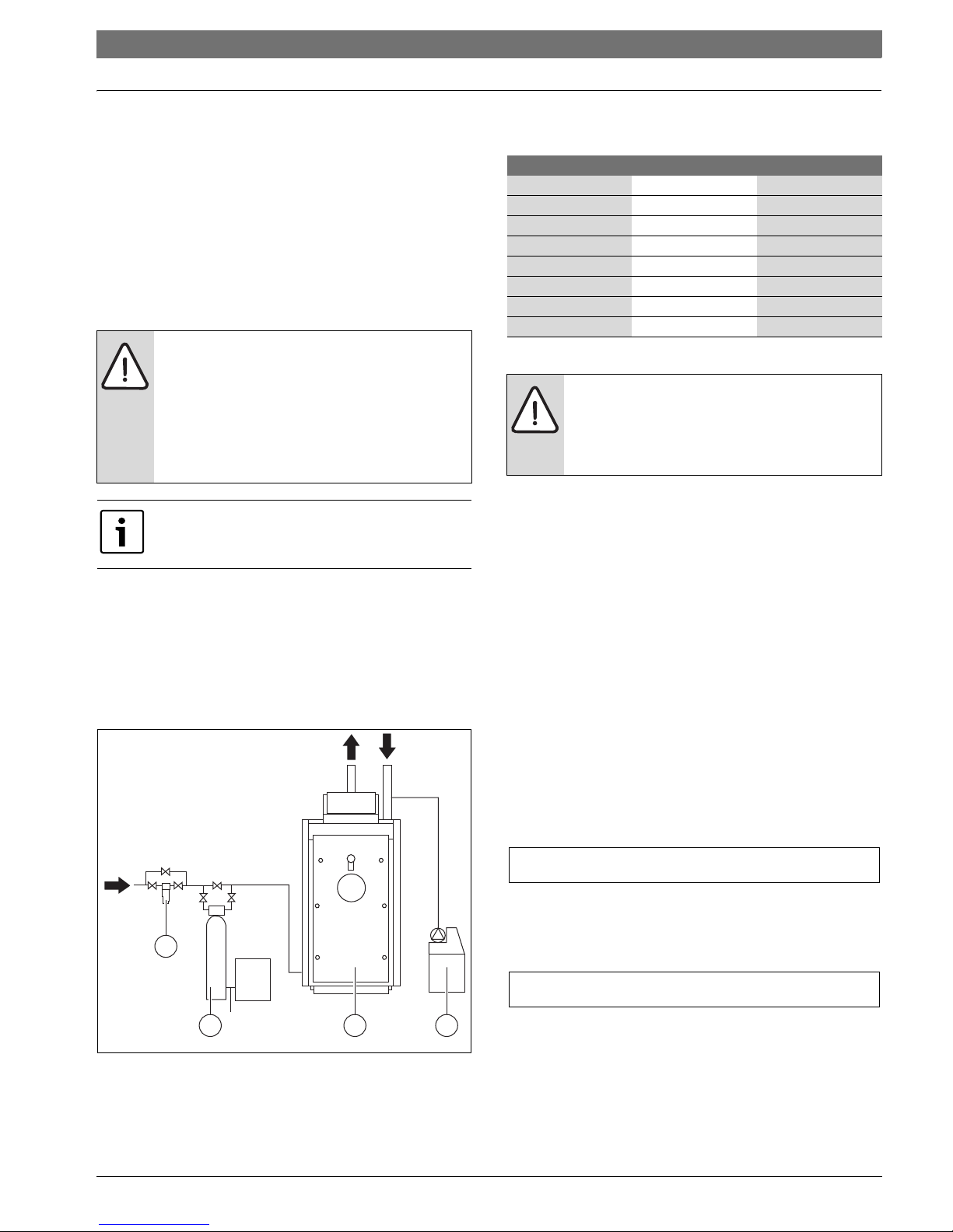
Typical layouts of water treatment systems
Fig. 7 Water treatment for heating installations
[1] Filter
[2] Water softener
[3] Boiler
[4] Chemical treatment unit
Chemical and physical requirements of heating system water
3.2 Central heating system
Possible causes for corrosion and limescale
Typical problems encountered in central heating systems include:
• the breakage of heated surfaces through overheating caused by the
thermal insulation of limescale deposits on the water side
• oxygen corrosion
• deposit corrosion
• stray current corrosion
• diffused and localized acid corrosion.
3.2.1 Limescale deposits
Limescale forms when the calcium and magnesium bicarbonates that
are dissolved in the water at ambient temperature become chemically
transformed when the water is heated.
Calcium bicarbonate forms calcium carbonate, water and carbon
dioxide, while magnesium bicarbonate transforms into magnesium
hydroxide and carbon dioxide.
Calcium bicarbonate Ca(HCO
3)2
when temperature is increased:
Form. 1 Calcium bicarbonate changes when temperature is increased
Magnesium bicarbonate Mg(HCO3)
2
when temperature is increased:
Form. 2 Magnesium bicarbonate changes when temperature is
increased
Calcium carbonate and magnesium hydroxide precipitate to form
insoluble deposits that adhere and compact on surfaces to form
limescale, a substance with a high thermal insulating power.
Inside a boiler, limescale forms mainly in areas subj ect to direct heat and
high temperatures. It is so common to find deposits localized in a few
NOTICE:
If it proves impossible to treat the heating system water
supply properly because the water charging system is
automatic and uncontrolled, if there are no barriers
installed to prevent water oxygenation, and if the
heating system includes an open expansion vessel, then
the boiler itself must be separated from the heating
system by means of a heat exchanger.
Installation must conform to any and all national, fed eral,
state and local standards and codes.
Y
6 720 805 218-17.1T
1
32 4
Parameters Unit of measure Heating water
pH 7.5- 9,5
Hardness ppm <50
Electrical conductivity s/cm < 100
Chlorides mg/l <10
Sulphides mg/l <10
Nitrides mg/l <10
Oxygen in solution mg/l –
Iron (Fe) mg/l <0.5
Table 7 Requirements of heating system water
NOTICE:
Chemical products used for water treatment must be
compatible with applicable water pollution laws.
Provided they are properly applied, these laws
guarantee the safe functioning of the heating system.
CaCO3H2OCO
2
++
Mg OH22CO
2
+
14 | Water treatment
SB625WS/SB745WS6 720 805 218 (2013/02)
specific areas, where temperature is the highest. A coating of limescale
of only 1 mm can cause severe overheating in metal parts and
consequent damage through thermal stress. It is continuous topping up
(automatic fill from incoming water) that causes thick deposits to form,
leading to boiler breakdown.
3.2.2 Deposit corrosion
Deposit corrosion is an electro-chemical phenomenon caused by the
presence of foreign bodies (sand, rust, etc.) in the water mass. These
solid substances generally form deposits (sludge) in the bottom of the
boiler.
The lower parts of the boiler can therefore be affected by a chemical
reaction of micro-corrosion caused by the electrochemical potential
difference created between the metal (steel) and the impurities around
it.
3.2.3 Stray current corrosion
Stray current corrosion is not common, but can be caused by the
different electrical potentials of the boiler water and the metal body of
the boiler or piping creating a cathode/anode effect.
All metal parts of the boiler should therefore be connected to an efficient
ground (earth) point, even though this form of corrosion is actually
caused by the passage of DC current, no longer used for domestic
power. Stray current corrosion is easily identified by the regular tiny
conical holes it leaves.
3.2.4 Diffused and localized acid corrosion
Other forms of corrosion exist that are harder to see but nonetheless
dangerous because they affect the entire heating system and not just the
boiler.
These forms of corrosion are generally due to the water becoming acidic
(pH < 7), and are caused by:
• Incorrect water softening and the presence of carbon dioxide (which
lowers the water’s pH). Carbon dioxide is released more easily in
softened water and also forms during the limescale formation
process. Acid corrosion is diffused and attacks the entire system
more or less uniformly
• Incorrect acid washing (e.g. washing done without a passivating
agent). Acid introduced into the system can cause localized
perforation if it is not properly removed from all parts of the system.
The formation of corrosion can easily be detected by analyzing the
chemical composition of the water. Even a minimal iron content is a
clear sign that corrosion is occurring.
3.3 New central heating systems
Mistakes to avoid and precautions.
To eliminate contact between system water and the air, the following is
required:
• ensure that the expansion vessel is a closed vessel, and of the correct
size and pre-charge pressure (the pressure should be checked
periodically)
• ensure that the system is always kept at a pressure higher than
atmospheric pressure at all points (including the pump suction side)
and at all operating conditions (precisely because the seals, gaskets
and joints in a water circuit are designed to resist pressure from
within, but not to resist a vacuum within)
• ensure that no part of the system is made from materials that are
permeable to gases (e.g. plastic pipes with no oxygen barrier used in
floor heating systems).
The heating system should not need any further topping up once it is
filled and bled of all air.
Any top-ups need to be monitored (by a meter), treated and recorded in
the heating system’s technical log. The presence of a water softener in
conjunction with an automatic filling system is not sufficient to ensure
proper performance.
If more than one boiler is installed in a large system, all boilers must be
switched on at the same time to ensure that any possible limescale
formation is uniformly distributed.
3.4 Reconditioning old heating systems
Frequent mistakes and necessary precautions.
If a boiler must be replaced, do not refill the entire central heating circuit
if the quality of water in it conforms to requirements.
If the quality of water fails to conform to requirements, either
recondition the old water or separate the water circuits (water in the
boiler circuit must conform to requirements).
Conclusions
Never forget that proper water conditioning and proper heating system
design not only guarantee safety and security but also ensures
significant savings in maintenance costs and overall thermal efficiency.
3.5 Elimination air and gas from central heating system
When designing new heating systems, it is necessary to eliminate the air
and other gases that form in the system.
Recently added fill or top-up water loses much of its volume in the first
few days because it releases gases. With new systems you should
therefore initially check the heating water pressure on a daily basis, and
then at gradually longer intervals. Air and gas in the water system not
only causes the corrosion problems listed above, but also reduces
thermal efficiency, causing pump failure and noise and vibration
throughout the heating system. Air bubbles and gas inevitably form in
heating circuits during normal functioning, especially if the precautions
listed above are not fully respected.
The technical details provided in this section refer
specifically to domestic and industrial hot water heating
systems with working temperatures up to 210 °F
(98,8 °C).
NOTICE:
The original system filling water and any topping up
water must always be filtered (using synthetic or metal
mesh filters with a filtration rating of no less than 50
microns) to prevent sludge from forming and triggering
deposit induced corrosion.
NOTICE:
Loss of water from the system, and the consequential
need to add water, can be caused not only by leaks from
the circuit, but also from the incorrect sizing of the
expansion vessel or precharge pressure. (If normal
thermal expansion causes pressure in the system to
increase beyond the setting of the safety valve, that
safety valve will open continuously.)
The expansion vessel size should be corrected to
prevent unnecessary safety valve blow-off.
Water treatment | 15
6 720 805 218 (2013/02)SB625WS/SB745WS
In particular:
• as temperature increases, oxygen becomes less watersoluble and
bubbles begin to form.
• CO2 (carbon dioxide) is generated as the carbonates of calcium and
magnesium precipitate out.
• the chemical oxidation of the metals in the system also generates
hydrogen.
These gases must be eliminated as they are formed. The system needs
to be designed and installed so that all gases can be vented quickly,
easily, and effectively.
3.6 Use of Antifreeze
In areas where freezing may occur, an antifreeze may be added to the
system water as protection. Please adhere to the specifications
provided by the antifreeze manufacturer.
▶ Use the anti-freeze manufacturer’s data to determine the anti-freeze
ratio for the desired freeze protection temperature.
▶ Do not exceed 50% antifreeze mix ratio and do not use antifreeze
other than specifically made for hot water heating systems.
Do not use automotive silicate-based antifreeze in the
heating system.
16 | Transport
SB625WS/SB745WS6 720 805 218 (2013/02)
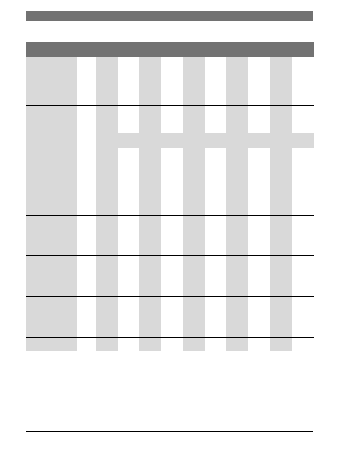
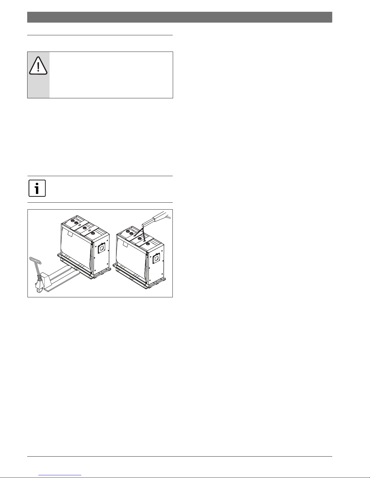
4 Transport
▶ Only use lifting equipment of adequate capacity.
▶ Remove the transport straps and the wooden pallet before
positioning the boiler.
▶ For lifting using a rigging crane, use only the lifting provisions
supplied.
▶ When lifting the boiler using chains, make sure that at least two chains
are load-bearing. Lift up very carefully.
▶ Maintain less than a 45 degree angle with the vertical when lifting the
boiler with chains or cables.
▶ The rigging crane must be operated by trained personnel.
Fig. 8 Transport
WARNING: Risk of injury from carrying heavy loads and
inadequately securing loads for transport.
▶ Use suitable means of transportation, e.g. several
pallet trucks, a forklift truck, crane or heavy duty
rollers.
▶ Secure the load against falling.
Never pull retaining straps (fixing straps, chains) over
the boiler insulation.
6 720 805 218-14.1T
 Loading...