

Bosch BTOK Installation Instructions Manual
6720645551-00.1V
Installation Instructions
Outdoor kit
For models: C1210ESC, C1210ES, C1050ES, 940ESO, 940ES,
830ES
Part no. BTOK
Warning: This kit must be installed by a qualified
installer in accordance with these instructions and
all applicable codes and requirements of the
authorities having jurisdiction.
6 720 645 551 (2010/06) US
6 720 645 551
2
Outdoor installation
1 Outdoor installation
1.1 Warnings
This outdoor kit includes:
• Supports (2) with screws
• Sealing gasket
• Control panel shield
• Outdoor vent cap.
Danger: The top of the outdoor kit will
get very hot during operation. Keep
away from children. Install heater in a
location where the top of the kit cannot
be reached by small children.
Danger: Flue gas will be released
through the outdoor kit. Flue gas is very
hot and contains carbon monoxide. The
outdoor kit cannot be installed on a
water heater mounted indoors. To
prevent risk of fire and carbon monoxide
poisoning, maintain all clearances
indicated in these instructions.
Danger: Do not place or store any
combustible material within 5 feet of the
appliance. Maintain specified clearance
to combustibles on the wall where the
appliance is installed and any adjacent
walls or overhang. Observe all
clearances required in this manual.
Danger: Surface temperature of the kit
is less than 140°F, except highest top
surface which may reach 300°F.
Warning: Do not mount water heater
directly onto vinyl siding, see Fig. 10.
Danger: the freeze prevention kit on
the appliance is designed to provide
protection from temperatures down to
approximately 5°F for short term
conditions only. It will not protect the
appliance in areas where the
temperature is routinely expected
to be below freezing. The freeze
prevention kit will not protect plumbing
outside the appliance from freezing.
Precautions must be taken:
B Always drain the water heater if it will
be exposed to long term freezing
conditions.
Danger: the water in this appliance is
cold and always remains cold except for
the times when the burner is on. In the
event of power outage in conjunction
with freezing temperatures, it is
recommended that the heater be
drained.
Warning: Damage to the appliance
from freezing is not covered under the
manufacturer's warranty.
6 720 645 551
Selecting heater location
3
2 Selecting heater location
Before proceeding, read the water heater installation
manual. If the information in that manual is not followed
exactly, a fire, explosion or poisoning by carbon monoxide may result causing property damage, personal injury
or death.
B This appliance is not designed to be installed
outdoors in climates that commonly fall below
freezing (32°F).
B Choose an outside wall for the installation. Installa-
tion on a wall protected by an overhang above is recommended.
B Size the water and gas connections according to the
instructions in the water heater installation manual.
Use unions when connecting both water lines and
gas supply line to the heater.
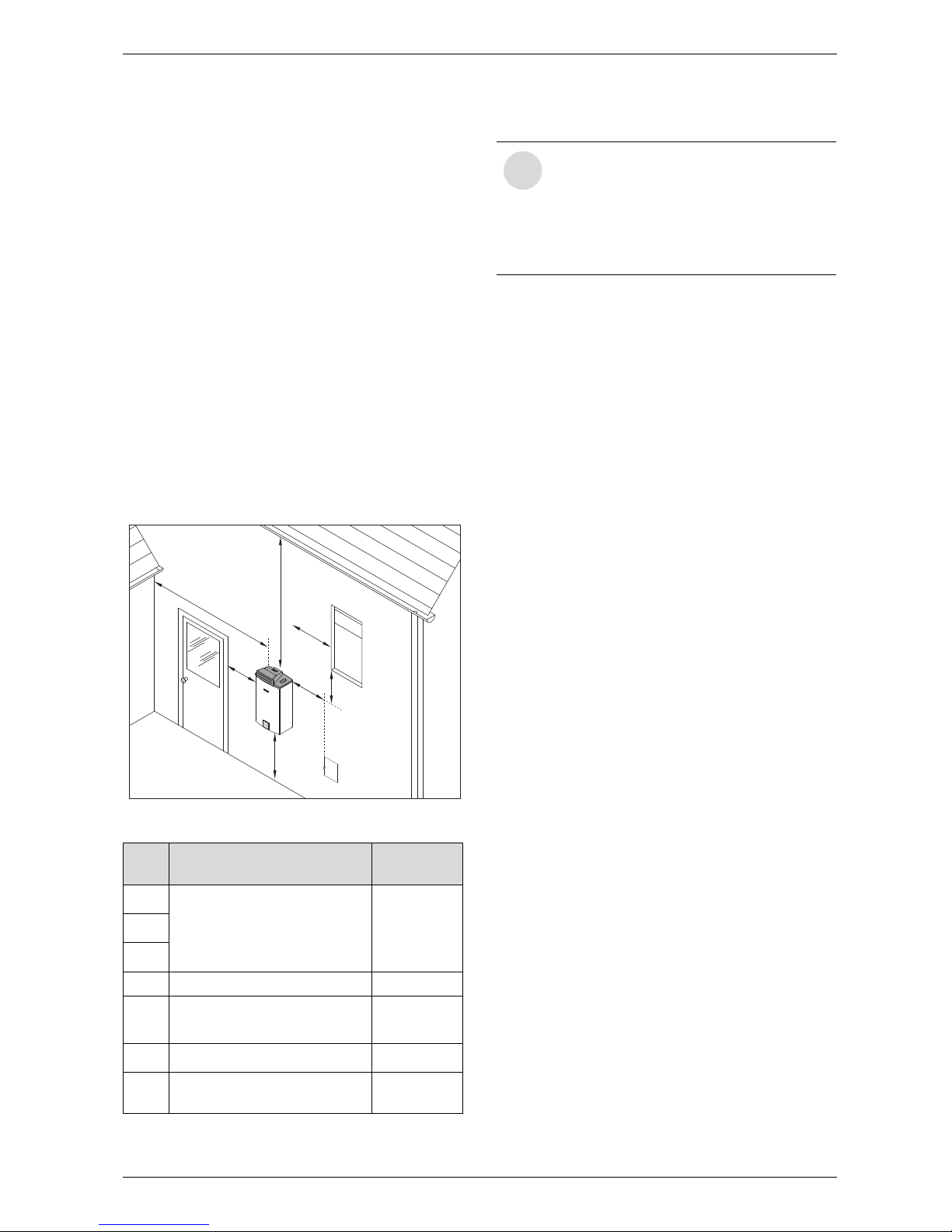
Minimum clearances
If the appliance is installed under an overhang, there
must be a minimum 36” clearance from the top of the
appliance and the mounting area must be open in front
and on the sides of the appliance.
Fig. 1
Ref. Description
Min.
distances
A
Directly below or adjacent to
an opening; operable
windows, doors and any fresh
air openings
≥ 1 ftB
C
D From any adjacent wall ≥ 1 ft
E
Below a gutter, sanitary
pipework, eaves or overhang
≥ 3 ft
F Above ground ≥ 1 ft
G
From a gas meter or gas
regulator
≥ 3 ft
Table 1 Clearances
6720645551-10.1V
D
A
B
G
E
C
F
i
Best practice note: The clearances in
Fig. 1 and table 1 are the minimum
allowed by the standard.
When possible consider maximizing the
clearances A, B, C, D and E to allow for
the effects of wind and frequently used
door and window openings.
6 720 645 551
4
Installing outdoor kit
3 Installing outdoor kit
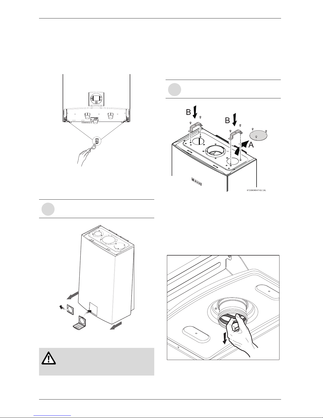
Replace the control panel shield
B Loosen the two Philips head screws located on
bottom rear of cover (see Fig. 2).
Fig. 2 Loosen the two screws
B Remove the front cover panel and replace the
original control panel shield with shield provided in
the kit, see Fig. 3.
Fig. 3 Replace the control panel shield
B After replacing the control panel shield re-position
the front cover.
B 1. Remove the cover plate (A) from the top of the
appliance, as shown in Fig. 4.
Fig. 4
B 2. Attach the supports (B) to the appliance with the
four provided screws, as shown in Fig. 4.
Before mounting the outdoor kit on the appliance:
Remove the exhaust seal from outdoor vent cap:
For condensing appliances only:
B Remove inner seal, see Fig. 5.
Fig. 5 Condensing appliances only
(C1050ES, C1210ESC, C1210ES)
i
This applies for all models except for the
model 940ESO.
Warning: The control panel shield
must always remain closed, except
when making adjustments, to prevent
damage to heater from weather.
6720608547-14.1AL
1.
1.
3.
2.
i
This applies for all models except for the
model 940ESO.
6720645551-16.1V
6 720 645 551
Installing outdoor kit
5
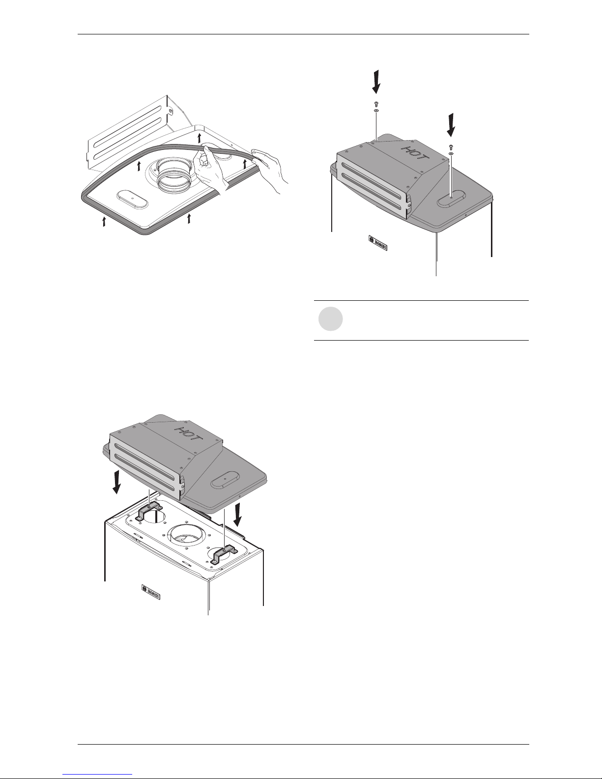
B 3. Attach the gasket provided with the kit as shown
in Fig. 6.
Fig. 6
B 4. Install supplied Freeze Prevention Kit (separate
packaging). Follow separate installation instructions
provided with Freeze Prevention.
Note: Freeze Prevention is not designed to
protect the appliance during long durations
below freezing or to protect plumbing outside
the appliance. Always drain the water heater if
it will be exposed to long term freezing conditions.
B Position the outdoor vent cap on the top of the
appliance, as shown in Fig. 7.
Fig. 7
B Attach the outdoor vent cap to the appliance by
fastening the two provided screws and washers, see
Fig. 8.
Fig. 8
6720645551-15.1V
6720645551-11.1V
i
NOTE: Once this kit is installed, the
outdoor vent cap will need to be removed,
before removing front cover.
6720645551-12.1V
 Loading...