

Bosch BAT 430 Original Instructions Manual

BAT 430
de
Originalbetriebsanleitung
Ladegerät für 12 Volt und 24 Volt
Batterien
Manual original
es
Carga para baterias 12 voltios y 24
Original instructions
en
Charger for 12 volt and 24 volt
batteries
it
Istruzioni originali
Carica per batteria 12 Volt e 24 Volt
Notice originale
fr
Chargeur de 12 volt et 24 Volt
batteries
sv
Bruksanvisning i original
Batteriladdaren för 12 Volt och 24 Volt
nl
Oorspronkelijke gebruiksaanwijzing
Laadapparaat voor 12-volts en 24-volts
da
Original brugsanvisning
Ladeapparat til 12-volts og 24-volts
batterier
Původní návod k používání
cs
Nabíjecí přístroj pro akumulátory
o napětí 12 V a 24 V
pt
Manual original
Carregador para baterias de 12 Volt
e 24 Volt
Original driftsinstruks
no
Ladeapparat til 12-volts og 24-volts
batterier
Orijinal işletme talimatı
tr
12 Volt ve 24 Volt aküler için şarj cihazı
Alkuperäiset ohjeet
fi
Akkuvaraaja 12 ja 24 voltin akkuihin
Oryginalna instrukcja eksploatacji
pl
Ładowarka do akumulatorów
12 V i 24 V
zh
原始的指南
适用于 12 伏和 24 伏电池的充电器


| BAT 430 | 3BAT 430 | 3 | 3
de
Inhaltsverzeichnis Deutsch 4
Contents English 12
Sommaire français 20
Índice español 28
Indice italiano 36
Innehållsförteckning svenska 44
Inhoud Nederlands 52
Índice português 60
Sisällysluettelo Suomi 68
Indholdsfortegnelse Dansk 76
Innholdsfortegnelse norsk 84
Spis treści po polsku 92
Obsah česky 100
İçindekiler Türkçe 108
目录 中文 116
1 689 979 996 2012-10-24| Robert Bosch GmbH

4 | BAT 430 | de
Inhaltsverzeichnis Deutsch
1. Verwendete Symbolik 5
1.1 In der Dokumentation 5
1.1.1 Warnhinweise – Aufbau und Bedeutung 5
1.1.2 Symbole – Benennung und Bedeutung 5
1.2 Auf dem Produkt 5
2. Benutzerhinweise 5
2.1 Wichtige Hinweise 5
2.2 Sicherheitshinweise 5
3. Produktbeschreibung 6
3.1 Verwendung 6
3.2 Wichtige Hinweise zum Ladegerät 6
3.3 Lieferumfang 6
3.4 Gerätebeschreibung 6
3.5 Status LEDs 6
3.6 Umschalter Batterietemperatur 7
3.7 Funktionsbeschreibung 7
4. Bedienung 8
4.1 Einschalten/Ausschalten 8
4.2 Wichtige Hinweise zum Laden der Batterie 8
4.3 Batterie laden 9
4.4 Tiefentladene Batterie laden 9
4.5 Stützbetrieb und Pufferbetrieb 10
4.6 Hinweis bei Störungen 10
5. Instandhaltung 11
5.1 Reinigung 11
5.2 Ersatz- und Verschleißteile 11
5.3 Entsorgung 11
6. Technische Daten 11
1 689 979 996 2012-10-24| Robert Bosch GmbH
Verwendete Symbolik | BAT 430 | 5
de
1. Verwendete Symbolik
1.1 In der Dokumentation
1.1.1 Warnhinweise – Aufbau und Bedeutung
Warnhinweise warnen vor Gefahren für den Benutzer oder
umstehende Personen. Zusätzlich beschreiben Warnhinweise die Folgen der Gefahr und die Maßnahmen zur Vermeidung. Warnhinweise haben folgenden Aufbau:
Warnsymbol
Das Signalwort zeigt die Eintrittswahrscheinlichkeit sowie
die Schwere der Gefahr bei Missachtung:
Signalwort Eintrittswahr-
GEFAHR Unmittelbar drohende
WARNUNG Mögliche drohende
VORSICHT Mögliche gefährliche
1.1.2 Symbole – Benennung und Bedeutung
SIGNALWORT – Art und Quelle der Gefahr!
Folgen der Gefahr bei Missachtung der aufgeführten Maßnahmen und Hinweise.
¶ Maßnahmen und Hinweise zur Vermeidung
der Gefahr.
scheinlichkeit
Gefahr
Gefahr
Situation
Schwere der Gefahr
bei Missachtung
Tod oder schwere
Körperverletzung
Tod oder schwere
Körperverletzung
Leichte
Körperverletzung
1.2 Auf dem Produkt
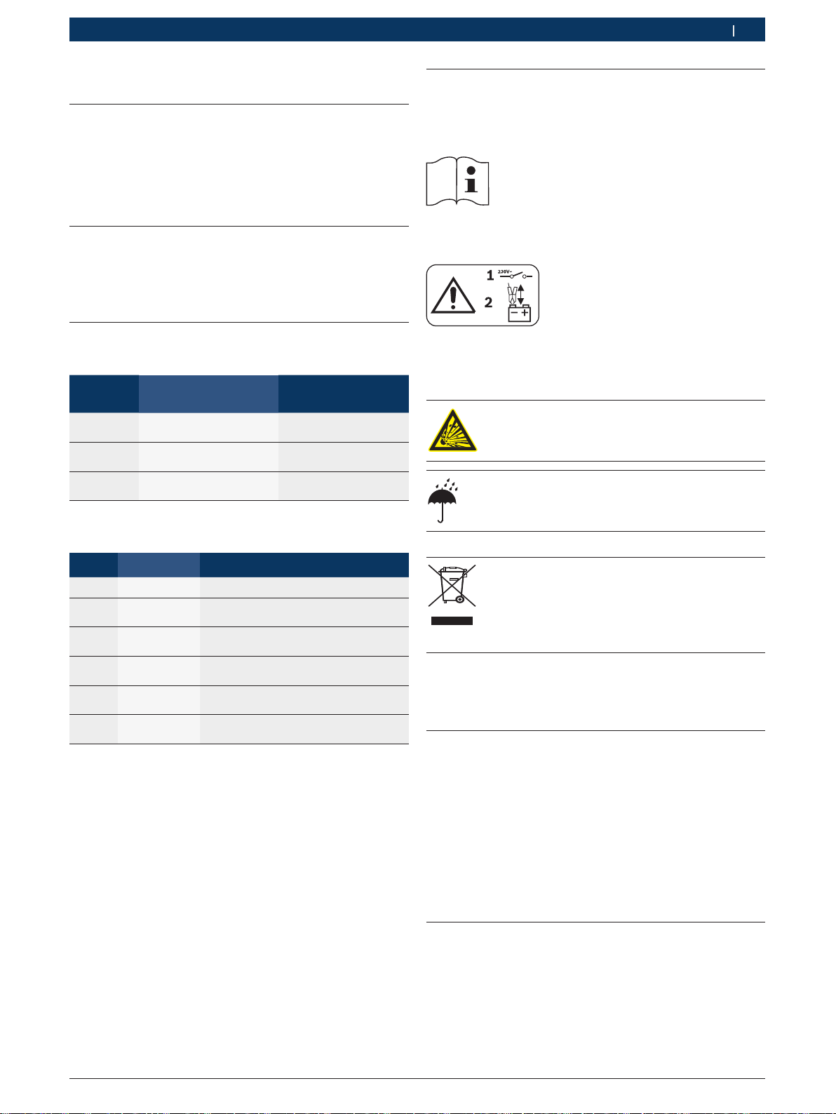
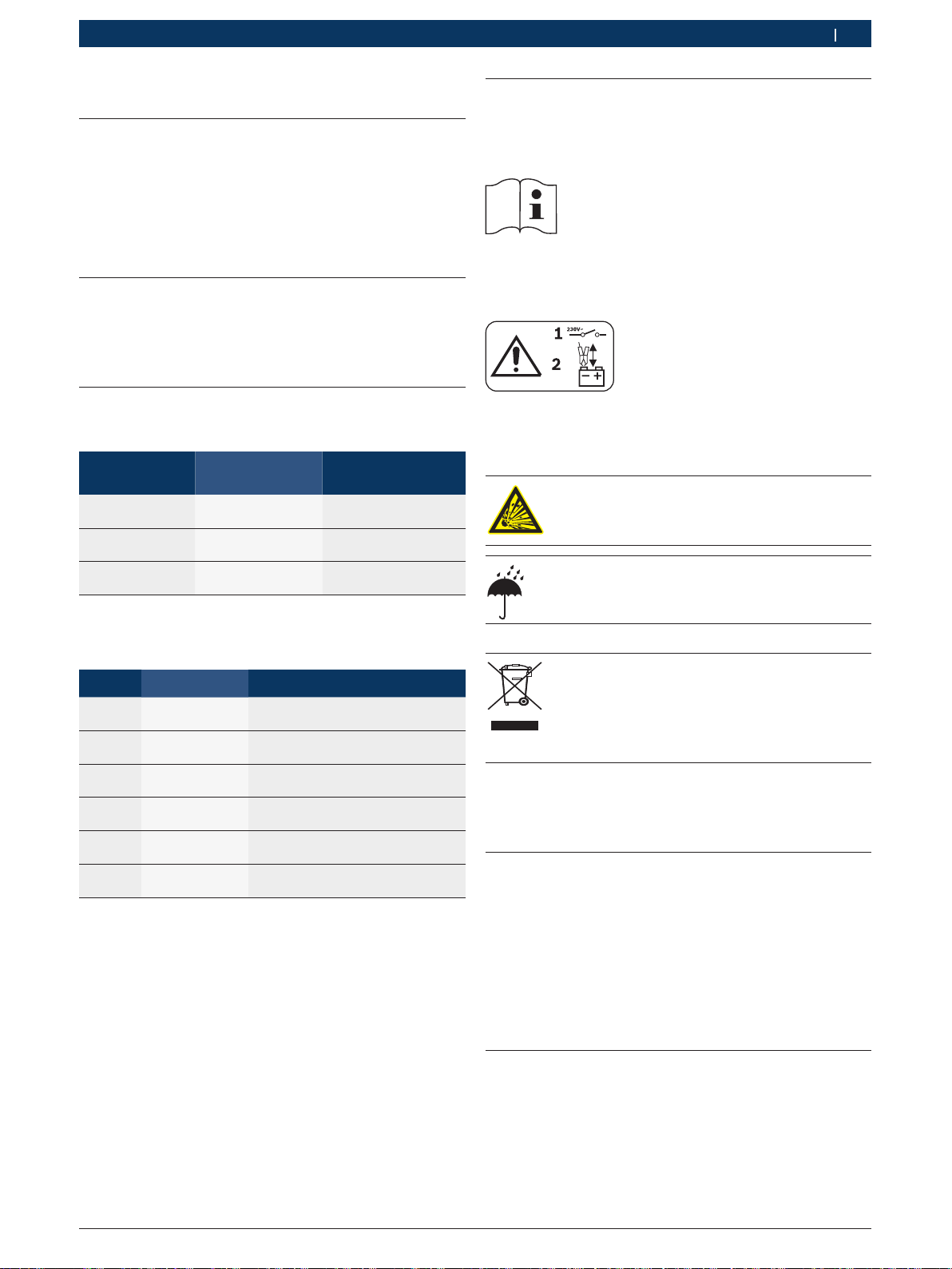
! Alle Warnzeichen auf den Produkten beachten und in
lesbarem Zustand halten.
Diese Betriebsanleitung und alle technischen Dokumentationen der verwendeten Komponenten beachten!
Vorsicht!
1. Ladegerät abschalten.
2. Ladezangen an- oder abklemmen.
Explosionsgefahr!
¶ Feuer, offenes Licht und Funkenbildung
vermeiden.
Vorsicht!
¶ Ladegerät vor Feuchtigkeit und Nässe
schützen.
Symbol Benennung Bedeutung
!
i
1.
2.
e
"
Achtung Warnt vor möglichen Sachschäden.
Information Anwendungshinweise und andere
Mehrschrittige
Handlung
Einschrittige
Handlung
Zwischenergebnis
Endergebnis Am Ende einer Handlungsaufforderung
nützliche Informationen.
Aus mehreren Schritten bestehende
Handlungsaufforderung.
Aus einem Schritt bestehende
Handlungsaufforderung.
Innerhalb einer Handlungsaufforderung
wird ein Zwischenergebnis sichtbar.
wird das Endergebnis sichtbar.
Entsorgung
Elektro- und Elektronik-Altgeräte einschließlich Leitungen und Zubehör sowie Akkus und
Batterien müssen getrennt vom Hausmüll entsorgt werden.
2. Benutzerhinweise
2.1 Wichtige Hinweise
Wichtige Hinweise zur Vereinbarung über Urheberrecht, Haftung und Gewährleistung, über die
Benutzergruppe und über die Verpflichtung des Unternehmens finden Sie in der separaten Anleitung
"Wichtige Hinweise und Sicherheitshinweise zu Bosch
Battery-Service-Products".
Diese sind vor Inbetriebnahme, Anschluss und Bedienung von BAT 430 sorgfältig durchzulesen und zwingend zu beachten.
2.2 Sicherheitshinweise
Alle Sicherheitshinweise finden Sie in der separaten
Anleitung "Wichtige Hinweise und Sicherheitshinweise
zu Bosch Battery-Service-Products". Diese sind vor Inbetriebnahme, Anschluss und Bedienung von BAT 430
sorgfältig durchzulesen und zwingend zu beachten.
1 689 979 996 2012-10-24| Robert Bosch GmbH
6 | BAT 430 | Produktbeschreibungde
aIaI
3. Produktbeschreibung
3.1 Verwendung
Mit dem leistungsstarken Batterieladegerät BAT 430
können 12 Volt oder 24 Volt Blei-Säure-Batterien jeder
Bauart geladen werden. Insbesondere Batterien mit
festgelegtem Elektrolyt (Gel- Technologie oder Vlies/
AGM-Technologie) werden in optimaler Weise geladen.
Sie können die Batterien sowohl am Fahrzeug im eingebauten Zustand als auch im ausgebauten Zustand
laden. BAT 430 kann auch zum Stützen und Puffern des
Bordnetzes verwendet werden.
Die vorgesehenen Einsatzbereiche des BAT 430 sind
Autowerkstatt, TÜV, Tankstelle und der Batteriehandel.
i BAT 430 sind ausschließlich zum Laden von einwand-
freien Blei-Säure-Batterien mit einer Nennspannung
von 12 Volt oder 24 Volt geeignet.
3.2 Wichtige Hinweise zum Ladegerät
¶ Sie müssen den BAT 430 waagrecht auf festen
Untergrund stellen. Der Standort muss ausreichend
stabil sein. Beachten Sie das Gerätegewicht und das
Gewicht der zu ladenden Batterie.
¶ Schützen Sie den BAT 430 vor Feuchtigkeit und
Nässe.
¶ Decken Sie den BAT 430 nicht ab. Stellen Sie den
BAT 430 so auf, dass ringsum ein Raum von mindestens 15 cm zur Entlüftung frei ist.
3.3 Lieferumfang
R BAT 430
R Betriebsanleitungen
3.4 Gerätebeschreibung
B
O
S
C
H
10
0
2
0
3
0
D
C
A
M
P
E
R
E
S
IU
I
alal
30
A
2
24
V
AUTO
12
V
1
2
3
4
5
A
Start
6
BAT 430
120
80
160
40
200
200
A
h
7
8
9
4510017 Ko
10
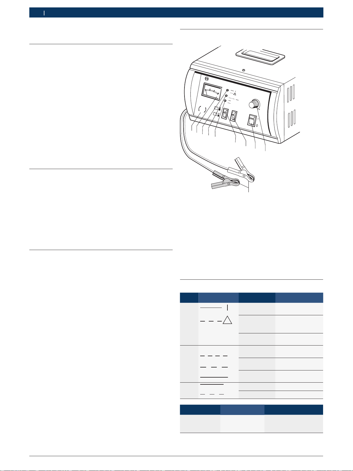
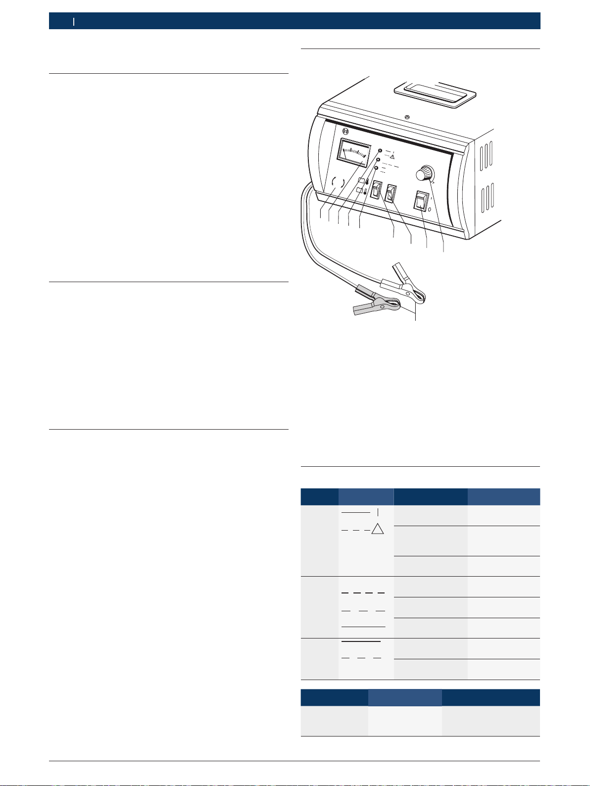
Fig. 1: BAT 430
1 Symbol "Automatische Erkennung 12 Volt / 24 Volt Batterie"
2 Anzeigeinstrument für Ladestrom
3 Rote LED für „Netz ein, Falschpolung, Störung oder Überlast“
4 Grüne LED für „Ladevorgang“
5 Gelbe LED für „Stützbetrieb / Pufferbetrieb“
6 Umschalter für Batterietemperatur
7 Starttaste für den Ladevorgang
8 Netzschalter
9 Regler zur Einstellung der Batteriekapazität
10 Ladeleitung mit vollisolierten Ladezangen
3.5 Status LEDs
LED Symbol Zustand Funktion
Rot
Grün
IU
I
Gelb
Status Gelbe LED Grüne LED
Tiefentladene
Batterie wird geladen
Blinkt
(1 Sekunden-Takt)
Leuchtet BAT 430 eingeschal-
tet
Blinkt Falschpolung, Stö-
!
rung
oder Überlast
Aus BAT 430 ausge-
schaltet
Blinkt
Hauptladung läuft
(schnell)
Blinkt
Nachladung läuft
(langsam)
Leuchtet Erhaltungsladung
läuft
Leuchtet 13,5 V / 27.0 V 30 A
Blinkt 12.0 V / 24.0 V 2 A
Blinkt
(1 Sekunden-Takt)
1 689 979 996 2012-10-24| Robert Bosch GmbH
Produktbeschreibung | BAT 430 | 7 de
Ladekennlinie
3.6 Umschalter Batterietemperatur
Symbol Funktion
Batterietemperatur warm (> 15 °C)
Batterietemperatur kalt (<15 °C)
3.7 Funktionsbeschreibung
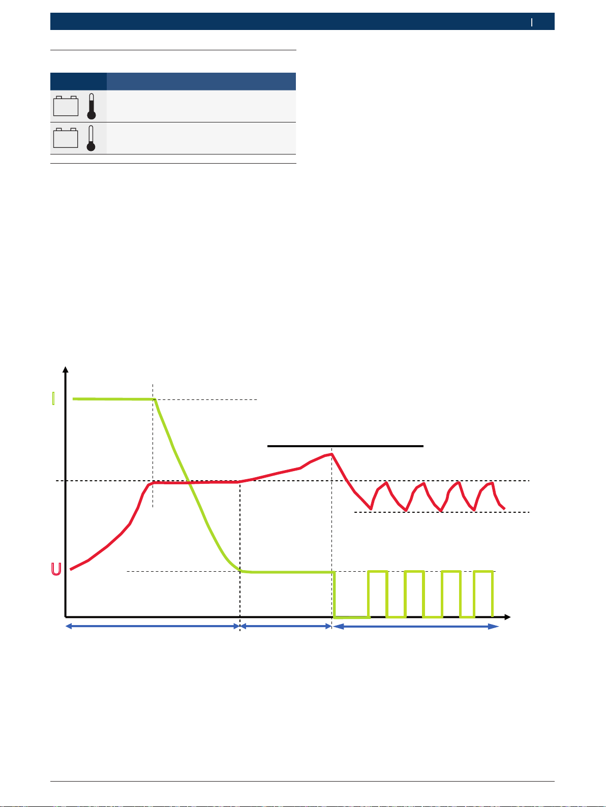
In Abbildung 2 wird die Ladekennlinie des BAT 430 gezeigt.
In der Phase 1 des Ladevorgangs beträgt der Ladestrom
ca. 15 % der am Regler (Fig 1, Pos. 8) eingestellten
I
1
Batteriekapazität. Die grüne LED blinkt in rascher Folge.
Wenn die Batterie die Ladeendspannung U
hat, beginnt der Ladestrom I
zu sinken. Jetzt sind ca.
1
65 % der Batteriekapazität erreicht. Die Batterie ist als
Starterbatterie einsatzfähig. Die Phase 1 (Hauptladung)
ist beendet, wenn der Ladestrom I
ca. 1% der Batte-
1
riekapazität unterschreitet. Die Batterie ist dann zu ca.
97 % geladen.
erreicht
1
In der Phase 2 beträgt der Ladestrom I2 ca. 1 % der
eingestellten Batteriekapazität. Die grüne LED blinkt in
langsamer Folge. Phase 2 ist zeitgesteuert und dauert
65 % der Hauptladezeit (Phase 1). Die Ladespannung
wird auf U2 begrenzt. Am Ende der Phase 2 leuchtet die
grüne LED mit Dauerlicht.
Beispiel: Bei einer eingestellten Batteriekapazität von
120 Ah beträgt der Ladestrom I
strom I
ca. 1,2 A.
2
ca. 18 A und der Lade-
1
In der Phase 3 wird der Ladestrom immer dann aktiviert, wenn die Batterie die Spannung U
unterschreitet.
3
Der Ladestrom bleibt so lange aktiv, bis die Ladespannung U
wieder erreicht ist.
1
I
U1warm = 14,0V/28,0V
kalt = 14,4V/28,8V
U
1
I2= 1% des Ah Reglers
U
Grüne LED blinkt
in rascher Folge
= 15% des Ah Reglers
I
1
Phase 1
Phase 2
Grüne LED blinkt
in langsamer Folge
warm = 14,4V/28,8V
U
2
kalt = 14,8V/29,6V
U
2
Phase 3
Grüne LED mit
Dauerlicht
U3= 12,8V/25,6V
t
Fig. 2: Ladekennlinie BAT 430 (schematische Darstellung)
1 689 979 996 2012-10-24| Robert Bosch GmbH

8 | BAT 430 | Bedienungde
4. Bedienung
4.1 Einschalten/Ausschalten
Die Spannungsversorgung für das Batterie-Ladegerät
erfolgt vom Lichtnetz. Das Gerät ist werkseitig auf
230 V, 50/60 Hz eingestellt. BAT 430 wird über den
Netzschalter (Fig. 1, Pos. 8) eingeschaltet oder ausgeschaltet.
i BAT 430 erkennt automatisch, ob eine 12 Volt Batte-
rie oder eine 24 Volt Batterie (Reihenschaltung von
zwei 12 Volt Batterien) angeschlossen ist.
i Der Stützbetrieb wird ausgeführt, wenn die Lade-
zangen nach dem Einschalten und der Pufferbetrieb
wird ausgeführt, wenn die Ladezangen vor dem
Einschalten angeklemmt werden (siehe Kap. 4.5).
4.2 Wichtige Hinweise zum Laden der Batterie
Bei stechendem Gasgeruch akute
Explosionsgefahr!
¶ Vermeiden Sie Feuer, offenes Licht und
Funken bildung!
¶ Schalten Sie BAT 430 nicht aus!
¶ Entfernen Sie nicht die Ladezangen!
¶ Belüften Sie den Raum sofort gut!
¶ Stellen Sie den Drehsteller auf Linksan-
schlag (geringster Ladestrom)!
¶ Schalten Sie nach dem Belüften den Netz-
schalter des BAT 430 auf „0“ (AUS)!
¶ Lassen Sie die Batterie durch eine Bosch-
Kundendienststelle überprüfen.
¶ Batterien nur in gut belüfteten Räumen laden.
¶ Feuer, offenes Licht und Funkenbildung beim Laden
der Batterie vermeiden.
¶ Zum Laden nur intakte Batterien parallel schalten.
¶ Keine nicht aufladbare Batterien laden.
¶ Während des Ladevorgangs von tiefentladenen Batte-
rien, alle Verbraucher im Fahrzeug ausschalten.
¶ Die Netzanschlussleitung und die Ladeleitungen
müssen in einwandfreiem Zustand sein.
¶ Bevor BAT 430 mit dem Stromnetz verbunden wird,
müssen Sie den Netzschalter auf „0“ (AUS) stellen.
¶ Bei den Standard-Batterien die Zellenstopfen vor
dem Laden abschrauben.
¶ Beim Laden von Fahrzeugbatterien im eingebauten
Zustand die schwarze Ladezange (‒), entfernt von
Batterie und Benzinleitung, an die Karosserie anschließen.
¶ BAT 430 vor dem Abklemmen der Ladezangen ab-
schalten.
¶ Ladezangen niemals während des Ladevorgangs
abklemmen.
¶ Solange der Ladevorgang läuft darf die Batterie nicht
vom Bordnetz getrennt werden.
¶ Ladezangen niemals kurzschließen.
1 689 979 996 2012-10-24| Robert Bosch GmbH

Bedienung | BAT 430 | 9 de
4.3 Batterie laden
i Bei Falschpolung und Klemmenkurzschluss bleibt die
Ladespannung abgeschaltet.
i Die Batterie braucht während des Ladens nicht vom
Bordnetz getrennt zu werden.
Halten Sie zum Laden der Batterie folgenden Ablauf ein:
1. Bei Standardbatterien vor dem Laden die Zellenstopfen abschrauben.
2. BAT 430 einschalten.
Die rote LED muss dauernd leuchten
(Fig. 1, Pos. 3).
3. Ladezangen (Fig. 1, Pos. 10) polrichtig an die Batterie anklemmen. Zuerst die rote Ladezange an den
Pluspol (+) und dann die schwarze Ladezange an
den Minuspol (‒).
Die gelbe LED blinkt (Fig. 1, Pos. 5).
4. Umschalter für "kalte und warme Batterien" auf die
richtige Position stellen (Fig. 1, Pos. 6). Zu beachten
ist, dass nur die Temperatur der Batterie zu bewerten
ist.
5. Regler zur Vorgabe der Batteriekapazität
(Fig. 1, Pos.9) auf den Nennwert der Batterie drehen.
6. Starttaste (Fig. 1, Pos. 7) betätigen.
Die gelbe LED geht aus.
Die grüne LED blinkt in rascher Folge.
Ladestrom am Anzeigeinstrument kontrollieren
(Fig. 2, Phase 1).
4.4 Tiefentladene Batterie laden
BAT 430 wird nach dem polrichtigen Anklemmen an die
Batterie automatisch aktiv und geht in den Stützbetrieb
oder in den Pufferbetrieb (siehe Kap. 3.5). Je nach Ladezustand der Batterie kann dabei vorübergehend eine
Überlast auftreten (rote LED blinkt).
Sobald die Starttaste (Fig. 1, Pos. 7) betätigt wird, beginnt bei einer tiefentladenen Batterie zunächst eine
schonende Ladung (grüne und gelbe LED blinken im
1-Sekunden-Takt). Die Ladestromstärke ist von der Einstellung des Reglers für die Batteriekapazität
(Fig. 1, Pos. 9) abhängig. Der Übergang zum Ladevorgang erfolgt automatisch (gemäß Kap. 4.3).
Zeigt BAT 430 nach dem Anklemmen an eine Batterie
keinerlei Reaktion, so kann durch Drücken der Starttaste
für länger als 2 Sekunden ein Ladeversuch gestartet werden. Bleibt dies erfolglos, so liegt eine Unterbrechung im
Ladekreis vor.
i BAT 430 erkennt automatisch, ob eine 12 Volt
Batterie oder eine 24 Volt Batterie angeschlossen
ist. Wenn die Spannung der 24 Volt Batterie unter
17 Volt liegt, muss jede der zwei in Reihe geschalteten 12 Volt Batterien separat geladen werden. Unter
17 Volt erkennt BAT 430 nur eine 12 Volt-Batterie
und würde daher den Ladevorgang auch nur für eine
12 Volt-Batterie durchführen. Während des Ladens
von tiefentladenen Batterien alle Verbraucher im
Fahrzeug ausschalten.
Der Ladevorgang läuft wie in Kap. 3.7 beschrieben ab.
i Wird während des Ladevorganges der Regler für die
Batteriekapazität verstellt oder der Umschalter für
die Batterietemperatur verändert, wird der Ladevorgang abgebrochen. Ein erneutes Drücken der Start-
taste bewirkt einen Neustart des Ladevorganges mit
den aktuellen Einstellungen.
7. Am Ende des Ladevorgangs BAT 430 ausschalten.
8. Ladezangen von der Batterie entfernen.
i Werden Batterien im zyklischen Betrieb genutzt
(Rollstühle, Kehrmaschinen, ...), sollte zumindest
jeder 3. Ladevorgang mit einer vollständigen Ladung
durchgeführt werden. Die Batteriekapazität bleibt so
am längsten erhalten.
1 689 979 996 2012-10-24| Robert Bosch GmbH

10 | BAT 430 | Bedienungde
4.5 Stützbetrieb und Pufferbetrieb
Die Ausgangsspannung des BAT 430 ist eine glatte
Gleichspannung und ist deshalb zum Stützen des Bordnetzes mit und ohne Fahrzeugbatterie geeignet.
Im Pufferbetrieb erhält BAT 430 den Ladezustand der
Batterie, wenn bei Motorstillstand Verbraucher versorgt
werden müssen.
BAT 430 stellt für diese Funktionen zwei Leistungsstufen zur Verfügung:
R 12,0 Volt / 24,0 Volt mit maximal 2 Ampere (Gelbe
LED blinkt) und
R 13,5 Volt / 27,0 Volt mit maximal 30 Ampere (Gelbe
LED leuchtet).
i In beiden Leistungsstufen werden die Ladezangen
erst nach Erkennen einer polrichtigen Batteriespannung vom Ladegerät versorgt.
In die schwächere Leistungsstufe (2 A) für den Stützbe-
trieb gelangt man durch Einschalten des BAT 430 ohne
Batterieanschluss. Die Ladezangen werden erst nach
dem Einschalten an die Batterie angeschlossen.
4.6 Hinweis bei Störungen
BAT 430 nach dem Einschalten ohne Funktion
(rote LED leuchtet nicht):
¶ Ziehen Sie den Netzstecker und überprüfen Sie die
Netzversorgung sowie die Netzleitung.
Rote LED blinkt nach dem Anklemmen der Batterie:
¶ Überprüfen Sie die Polung an der Batterie. Die rote
Ladezange muss am Pluspol (+) und die schwarze
Ladezange muss am Minuspol (‒) der Batterie angeschlossen sein.
¶ Überlast: Die maximalen Stromwerte für Pufferbe-
trieb und Stützbetrieb sind erreicht. Die rote LED
blinkt nicht mehr, wenn die Überlast beseitigt ist.
Wird während des Ladevorgangs der Umschalter für die
Batterietemperatur oder der Einsteller für die Batteriekapazität verstellt, kommt es zum Ladeabbruch und die
rote LED blinkt.
¶ Nach Drücken der Starttaste ist eine Verstellung nur
innerhalb 60 Sekunden möglich.
¶ Ein erneutes Drücken der Starttaste bewirkt einen
Neustart des Ladevorganges mit den aktuellen
Einstellungen.
In die stärkere Leistungsstufe (30 A) für den Puffer-
betrieb gelangt man, wenn vor dem Einschalten des
BAT 430 die Ladezangen angeschlossen werden und
bereits eine Batteriespannung größer 11,5 Volt / 23 Volt
anliegt.
! Eine bereits wirksame Leistungsstufe bleibt auch
beim Abklemmen der Ladezangen aktiv.
1 689 979 996 2012-10-24| Robert Bosch GmbH

Instandhaltung | BAT 430 | 11 de
5. Instandhaltung
! Alle Arbeiten an elektrischen Einrichtungen dürfen
nur Personen mit ausreichenden Kenntnissen und
Erfahrungen in der Elektrik durchführen!
5.1 Reinigung
! Keine scheuernden Reinigungsmittel und keine gro-
ben Werkstattputzlappen verwenden!
¶ Das Gehäuse nur mit weichen Tüchern und neutralen
Reinigungsmitteln säubern.
5.2 Ersatz- und Verschleißteile
Bezeichnung Bestellnummer
Ladeleitung mit PVC-Isolation
Netzanschlussleitung 2,5 m
<)
Verschleißteil
5.3 Entsorgung
BAT 430 unterliegt der europäischen Richtlinie 2002/96/EG (WEEE).
Elektro- und Elektronik-Altgeräte einschließlich Leitungen und Zubehör sowie Akkus und
Batterien müssen getrennt vom Hausmüll
entsorgt werden.
¶ Nutzen Sie zur Entsorgung die zur Verfügung
stehenden Rückgabesysteme und Sammelsysteme.
¶ Mit der ordnungsgemäßen Entsorgung von
BAT 430 vermeiden Sie Umweltschäden
und eine Gefährdung der persönlichen
Gesundheit.
<)
<)
1 684 460 275
1 684 461 168
6. Technische Daten
Eigenschaft Wert, Bereich
Ladestrom Maximal 30 A
Länge Ladeleitung
Querschnitt Ladeleitung 6 mm
Leistungsaufnahme 900 W
Gewicht 5 kg
Ladekennlinie IUIaIaI
Ladeendspannung bei Einstel-
lung > 15 °C
Spannungsbegrenzung der Nach-
ladung bei Einstellung > 15 °C
Ladeendspannung bei Einstel-
lung < 15 °C
Spannungsbegrenzung der Nach-
ladung bei Einstellung < 15 °C
Stützbetrieb
Pufferbetrieb
Funktions-Temperaturbereich 0 °C bis 40 °C
Netz-Spannung/-Frequenz 230 V, 50/60 Hz
Netzsicherung H 250 T 6,3 A
Batterie-Nennspannung 12 V / 24 V
Schutzart (DIN 40050) IP 20
Schutzklasse (DIN 40530) II
Abmessungen (B x H x T) 260 x 160 x 250 mm
Arbeitsplatzbezogener
Geräuschemissionswert (Lpa)
Störaussendungsgrad DIN 40839 Störaussen-
*)
Die Ladeleitungen dürfen nicht verändert werden!
*)
2 m
2
14,0 V / 28,0 V
14,4 V / 28,8 V
14,4 V / 28,8 V
14,8 V / 29,6 V
12,0 V / 24,0 V maximal 2 A
13,5 V / 27,0 V maximal 30 A
≤ 70 dB(A)
dungsgrad I
1 689 979 996 2012-10-24| Robert Bosch GmbH

12 | BAT 430 | en
Contents English
1. Symbols used 13
1.1 In the documentation 13
1.1.1 Warning notices Structure and meaning 13
1.1.2 Symbols in this documentation 13
1.2 On the product 13
2. User information 13
2.1 Important notes 13
2.2 Safety instructions 13
3. Product description 14
3.1 Application 14
3.2 Important information about the charger 14
3.3 Delivery specification 14
3.4 Description of unit 14
3.5 Status LEDs 14
3.6 Changeover switch for battery temperature 15
3.7 Function description 15
4. Operation 16
4.1 Turning on and off 16
4.2 Important information for charging the
battery 16
4.3 Charging the battery 17
4.4 Charge discharged battery 17
4.5 Back up and buffer mode 18
4.6 Faults 18
5. Maintenance 19
5.1 Cleaning 19
5.2 Spare and wearing parts 19
5.3 Disposal 19
6. Technical data 19
1 689 979 996 2012-10-24| Robert Bosch GmbH

Symbols used | BAT 430 | 13
en
1. Symbols used
1.1 In the documentation
1.1.1 Warning notices - Structure and meaning
Warning notices warn of dangers to the user or people in
the vicinity. Warning notices also indicate the consequences of the hazard as well as preventive action. Warning notices have the following structure:
Warning
symbol
The key word indicates the likelihood of occurrence and
the severity of the hazard in the event of non-observance:
Key word Probability of
DANGER Immediate impend-
WARNING Possible impending
CAUTION Possible dangerous
1.1.2 Symbols in this documentation
KEY WORD – Nature and source of hazard!
Consequences of hazard in the event of failure to observe action and information given.
¶ Hazard prevention action and information.
occurrence
ing danger
danger
situation
Severity of danger if instructions not observed
Death or severe injury
Death or severe injury
Minor injury
1.2 On the product
! Observe all warning notices on products and ensure
they remain legible.
Read this operating manual and all technical documentation for the used components!
Caution!
1. Turn off charger.
2. Connect or disconnect charging clips.
Risk of explosion!
¶ Avoid fire, open flame and sparks.
Caution!
¶ Protect charger from moisture and keep
dry.
Symbol Designation Explanation
!
i
1.
2.
e
"
Attention Warns about possible property damage.
Information Practical hints and other
Multi-step
operation
One-step
operation
Intermediate
result
Final result There is a visible final result on com-
useful information.
Instruction consisting of several steps.
Instruction consisting of one step.
An instruction produces a visible intermediate result.
pletion of the instruction.
Disposal
Dispose of used electrical and electronic
devices, including cables, accessories and
batteries, separately from household waste.
2. User information
2.1 Important notes
Important information on copyright, liability and warranty provisions, as well as on equipment users and company obligations, can be found in the separate manual
"Important notes on and safety instructions for Bosch
Battery-Service-Products". These instructions must be
carefully studied prior to start-up, connection and operation of the BAT 430 and must always be heeded.
2.2 Safety instructions
All the pertinent safety instructions can be found in
the separate manual "Important notes on and safety
instructions for Bosch Battery-Service-Products". These
instructions must be carefully studied prior to start-up,
connection and operation of the BAT 430 and must always be heeded.
1 689 979 996 2012-10-24| Robert Bosch GmbH

14 | BAT 430 | Product descriptionen
o
aIaI
3. Product description
3.1 Application
The powerful BAT 430 battery charger can be used to
charge any type of 12 volt or 24 volt lead acid batteries.
In particular, it provides optimum charging for batteries
with fixed electrolytes (gel technology or fleece/AGM
technology). You can charge the batteries either in the
vehicle while installed or when removed. The BAT 430
can also be used to back up or buffer the vehicle electrical system.
The BAT 430 is intended for use by workshops, inspection facilities, gas stations and battery dealers.
i The BAT 430 is designed exclusively for charging
lead acid batteries in perfect condition with a nominal voltage of 12 volts or 24 volts.
3.2 Important information about the
charger
¶ You must place the BAT 430 level on a solid surface.
The location must be sufficiently stable. Take into
account the weight of the unit and of the battery to
be charged.
¶ Protect the BAT 430 against humidity and moisture.
¶ Do not cover the BAT 430. Position the BAT 430 so
that there is at least 15 cm of space for ventilation
all the way around it.
3.3 Delivery specification
R BAT 430
R Operating instructions
3.4 Description of unit
B
O
S
C
H
10
0
2
0
3
0
D
C
A
M
P
E
R
E
S
IU
I
alal
30
A
2
24
V
AUTO
12
V
1
2
3
4
5
A
Start
6
BAT 430
120
80
160
40
200
200
A
h
7
8
9
4510017 K
10
Fig. 1: BAT 430
1 Symbol "Automatic recognition 12 Volt / 24 Volt Battery"
2 Display unit for charging current
3 Red LED for "Mains on, incorrect polarity, fault or overload"
4 Green LED for "Charging"
5 Yellow LED for "Back up/buffer mode"
6 Changeover switch for battery temperature
7 Start button for charging
8 Mains switch
9 Controller for setting battery capacity
10 Charging lead with fully insulated charging clips
3.5 Status LEDs
LED Symbol Status Functions
Red
Green
IU
I
Yellow
Status Yellow LED Green LED
Discharged
battery is charged
Illuminated BAT 430 turned on
Flashes Incorrect polarity,
!
fault or overload
Off BAT 430 turned off
Flashes(fast) Main charging
in progress
Flashes(slowly) Secondary charging
in progress
Illuminated Float charge in
progress
Illuminated 13,5 V / 27.0 V 30 A
Flashes 12.0 V / 24.0 V 2 A
Flashes
(1 second interval)
Flashes
(1 second interval)
1 689 979 996 2012-10-24| Robert Bosch GmbH

Product description | BAT 430 | 15 en
Characteristic charging curve
3.6 Changeover switch for battery temperature
Symbol Functions
Battery temperature warm (> 15 °C)
Battery temperature cold (<15 °C)
3.7 Function description
Figure 2 shows the characteristic charging curve for the
BAT 430.
In phase 1 of the charging process, the charging current
is approx. 15 % of the battery capacity set on the con-
I
1
troller (Fig. 1, Pos. 8). The green LED flashes rapidly.
When the battery has reached the final charge voltage
, the charging current I1 starts to fall. Around 65 % of
U
1
the battery capacity has now been reached. The battery can be used as a starter battery. Phase 1 (main
charging) is complete when the charging current I
below approx. 1% of the battery capacity. The battery is
then approx. 97 % charged.
falls
1
In phase 2, the charging current I2 is approx. 1 % of
the set battery capacity. The green LED flashes slowly.
Phase 2 is time-controlled and lasts for 65 % of the
main charging time (phase 1). The charge voltage is
limited to U2. At the end of phase 2 the green LED is
constantly lit.
Example: With a set battery capacity of 80 Ah, the
charging current I
is approx. 0.8 A.
rent I
2
In phase 3, the charging current is always activated
if the battery is below the voltage U
current remains active until the charge voltage U
reached.
is approx. 12 A and the charging cur-
1
. The charging
3
1
is
= 15% of Ah controller
I
I
1
U1Warm = 14,0V/28,0V
Cold = 14,4V/28,8V
U
1
U
I2= 1% of Ah controller
Phase 1
Green LED flashes rapidly
Phase 2
Green LED flashes slowly
Warm = 14,4V/28,8V
U
2
Cold = 14,8V/29,6V
U
2
U3= 12,8V/25,6V
Phase 3
Green LED constantly lit
t
Fig. 2: BAT 430 characteristic charging curve
(schematic representation)
1 689 979 996 2012-10-24| Robert Bosch GmbH

16 | BAT 430 | Operationen
4. Operation
4.1 Turning on and off
The power supply for the battery charger comes from
the lighting mains. The unit is factory set to 230 V,
50/60 Hz. The BAT 430 is turned on using the mains
switch (Fig. 1, Pos. 8).
i BAT 430 automatically recognizes whether a 12 Volt
battery or a 24 Volt battery (series connection of
two 12 Volt batteries) is connected.
i The back-up mode occurs if the terminal clips are
connected after switching on, and the buffer mode
occurs if the terminal clips are connected before
switching on (see Chapter 4.5).
4.2 Important information for charging the battery
If there is a pungent smell of gas, there is a
severe risk of explosion! Proceed as follows:
¶ Avoid fire, naked flames and sparks.
¶ Do not turn off the BAT 430.
¶ Do not remove the charging clips.
¶ Ventilate the room well immediately.
¶ Move the rotary actuator to the extreme
left (minimum charging current).
¶ After ventilating, turn the mains switch on
the BAT 430 to "0" (OFF).
¶ Have the battery checked by a Bosch cus-
tomer service center.
¶ Only charge batteries in well ventilated rooms.
¶ Avoid fire, naked flames and sparks while charging
the battery.
¶ Only connect intact batteries in parallel for charging.
¶ Do not attempt to charge non-rechargeable batteries.
¶ While charging totally discharged batteries, turn off
all consumers in the vehicle.
¶ The mains connecting lead and the charging leads
must be in perfect condition.
¶ Before connecting the BAT 430 to the mains, you
must set the mains switch to "0" (OFF).
¶ On standard batteries, unscrew the inspection plugs
before charging.
¶ When charging vehicle batteries in the installed condi-
tion, connect the black terminal clip (‒) to the body,
away from the battery and fuel pipe line.
¶ Turn off the BAT 430 before disconnecting the charg-
ing clips.
¶ Never disconnect the charging clips while charging is
in progress.
¶ The battery may not be disconnected from the vehicle
electrical system while charging is in progress.
¶ Never short circuit the charging clips.
1 689 979 996 2012-10-24| Robert Bosch GmbH

Operation | BAT 430 | 17 en
4.3 Charging the battery
i If there is incorrect polarity or a clip short circuit,
the charge voltage remains disconnected.
i The battery does not need to be disconnected from
the vehicle electrical system during charging.
Observe the following procedure for charging the battery:
1. On standard batteries, unscrew the inspection plugs
before charging.
2. Turn on the BAT 430.
The red LED must be constantly lit (Fig. 1, Pos. 3).
3. Connect charging clips (Fig. 1, Pos. 10) to the battery,
ensuring correct polarity. First connect the red terminal clip to the positive terminal (+) and then connect
the black terminal clip to the negative terminal (‒).
The yellow LED flashes (Fig. 1, Pos. 5).
4. Set the changeover switch for "cold and warm batteries" to the correct position (Fig. 1, Pos. 6). Ensure
that only the temperature of the battery is to be taken
into account.
5. Turn the controller for setting the battery capacity
(Fig. 1, Pos. 9) to the nominal value for the battery.
6. Press the start button (Fig. 1, Pos. 7).
The yellow LED goes off.
The green LED flashes rapidly.
Check charging current on display instrument
(Fig. 2, phase 1).
4.4 Charge discharged battery
After connecting to the correct terminals on the battery,
the BAT 430 activates automatically and goes into backup mode or buffer mode (see Chapter 3.5). Depending
on the state of charge of the battery, an overload can
occur temporarily (red LED flashes).
As soon as the start button is pressed (Fig. 1, Pos. 7),
a gentle charge initially starts on a discharged battery
(green and yellow LED flash in 1 second cycle). The
charging current strength depends on the setting of the
controller for the battery capacity (Fig. 1, Pos. 9). The
transition to the charging process occurs automatically
(in line with Chapter 4.3).
If the BAT 430 does not show any reaction after being
connected to a battery, then a charging attempt can
be started by pressing the start button for more than 2
seconds. If this is not successful, then there must be an
interruption in the charging circuit.
i BAT 430 automatically recognizes whether a 12 Volt
battery or a 24 Volt battery is connected. If the voltage of the 24 Volt battery is below 17 Volt, each of
the two 12 Volt batteries switched in series must
be charged separately. Below 17 Volt, BAT 430 only
recognizes a 12 Volt battery and would therefore
also only carry out the charging process for a 12 Volt
battery. Switch off all consumers in the vehicle when
charging discharged batteries.
Charging proceeds as described in section 3.7.
i If the controller for the battery capacity is adjusted
or the changeover switch for the battery temperature
changes position during charging, charging is discontinued. Pressing the start button again restarts
charging with the current settings.
7. When charging is complete, turn off the BAT 430.
8. Disconnect charging clips from the battery.
i If batteries are used in cyclic operation (wheelchairs,
road sweepers etc.) complete charging should be
carried out at least once in every three charges. This
maximizes the retention of battery capacity.
1 689 979 996 2012-10-24| Robert Bosch GmbH

18 | BAT 430 | Operationen
4.5 Back up and buffer mode
The output voltage from the BAT 430 is a flat d.c. voltage and is therefore suitable for backing up the vehicle
electrical system after removing the vehicle battery.
In buffer mode, the BAT 430 maintains the battery
charge level if consumers need to be supplied with
power when the engine is stopped.
The BAT 430 provides two power levels for these functions:
R 12.0 Volt / 24,0 Volt and maximum 2 Amp (yellow
LED flashing) and
R 13.5 Volt / 27,0 Volt and maximum 30 Amp (yellow
LED constantly lit).
i At both power levels, the charger does not supply
power to the charging clips until a battery voltage
with correct polarity has been detected.
The weaker power setting (2 A) for the back-up mode is
reached by switching on the BAT 430 without connecting it to a battery. The terminal clips are not connected
to the battery until after it has been switched on.
4.6 Faults
BAT 430 does not function after turning on (red LED
does not function):
¶ Disconnect the mains connector and check the
mains supply and the mains lead.
Red LED flashes after connecting the battery:
¶ Check the polarity of the battery. The red clip must
be connected to the positive pole (+) of the battery
and the black clip to the negative pole (‒).
¶ Overload: The maximum current values for buffer and
back up mode have been reached. The red LED stops
flashing when the overload has been eliminated.
If the changeover switch for the battery temperature or
the controller for the battery capacity is adjusted during charging, charging is discontinued and the red LED
flashes.
¶ After pressing the start button, adjustment is only
possible within 60 seconds.
¶ Pressing the start button again restarts charging
with the current settings.
The stronger power setting (30 A) for the buffer mode
is reached by connecting the terminal clips before
switching on
higher than 11.5 Volt / 23 Volt is present.
the BAT 430, where a battery voltage of
! The power setting that is already effective remains
active even when the terminal clips have been disconnected.
1 689 979 996 2012-10-24| Robert Bosch GmbH

Maintenance | BAT 430 | 19 en
Make use of the local return and collection
5. Maintenance
! Work on electrical equipment is only to be per-
formed by persons with sufficient knowledge and
experience of electrical systems!
5.1 Cleaning
! Do not use abrasive cleaning agents and coarse
workshop cloths!
¶ The housing and the LCD are only to be cleaned us-
ing a soft cloth and neutral cleaning agents.
5.2 Spare and wearing parts
Description Order number
Charging lead with PVC-insulation
Mains connecting cable 2,5 m
<)
Wearing parts
5.3 Disposal
The BAT 430 is subject to the European
directive 2002/96/EC (WEEE).
Dispose of used electrical and electronic
devices, including cables, accessories and
batteries, separately from household waste.
systems for disposal.
¶ Proper disposal of the BAT 430 prevents
environmental pollution and possible
health hazards.
<)
<)
1 684 460 275
1 684 461 168
6. Technical data
Property Value, Range
Charging current
Charging lead length
Charging lead cross-section 6 mm
Power consumption 900 W
Weight 5 kg
Characteristic charging curve IUIaIaI
Final charge voltage at setting >
15 °C
Voltage limit for secondary charg-
ing at setting > 15 °C
Final charge voltage at setting <
15 °C
Voltage limit for secondary charg-
ing at setting < 15 °C
Back up
Buffer mode
Function temperature range 0 °C bis 40 °C
Mains voltage / frequency 230 V, 50/60 Hz
Mains fuse H 250 T 6,3 A
Nominal battery voltage 12 V / 24 V
Protection type (DIN 40050) IP 20
Class of protection (DIN 40530) II
Dimensions (W x H x D) 260 x 160 x 250 mm
Work-related
noise emission value (Lpa)
Interference emission level DIN 40839 Interference
*)
The charging leads may not be changed!
*)
Maximal 30 A
2 m
2
14,0 V / 28,0 V
14,4 V / 28,8 V
14,4 V / 28,8 V
14,8 V / 29,6 V
12,0 V / 24,0 V maximal 2 A
13,5 V / 27,0 V maximal 30 A
≤ 70 dB(A)
emission level I
1 689 979 996 2012-10-24| Robert Bosch GmbH

20 | BAT 430 | fr
Sommaire français
1. Symboles utilisés 21
1.1 Dans la documentation 21
1.1.1 Avertissements -
Conception et signification 21
1.1.2 Pictogrammes utilisés dans
la présente documentation 21
1.2 Sur le produit 21
2. Consignes d'utilisation 21
2.1 Remarques importantes 21
2.2 Consignes de sécurité 21
3. Description de produit 22
3.1 Application 22
3.2 Remarques importantes concernant
le chargeur 22
3.3 Contenu de la livraison 22
3.4 Description de l'appareil 22
3.5 Etat LEDs 22
3.6 Inverseur de température de la batterie 23
3.7 Description du fonctionnement 23
4. Utilisation 24
4.1 Mise en marche/arrêt 24
4.2 Remarques importantes concernant
la charge de la batterie 24
4.3 Charge de la batterie 25
4.4 Chargement d'une batterie complètement
déchargée 25
4.5 Mode de fonctionnement support et
dispositif tampon 26
4.6 Indication des défauts 26
5. Maintenance 27
5.1 Nettoyage 27
5.2 Pièces de rechange et d'usure 27
5.3 Elimination 27
6. Caractéristiques techniques 27
1 689 979 996 2012-10-24| Robert Bosch GmbH
Symboles utilisés | BAT 430 | 21
fr
1. Symboles utilisés
1.1 Dans la documentation
1.1.1 Avertissements - Conception et signification
Les avertissements mettent en garde contre les dangers
pour l’utilisateur et les personnes présentes à proximité.
En outre, les avertissements décrivent les conséquences
du danger et les mesures préventives. La structure des
avertissements est la suivante :
Symbole
d’avertissement
Le mot clé indique la probabilité de survenue ainsi que
la gravité du danger en cas de non-observation :
Mot clé Probabilité
DANGER Danger direct Mort ou blessure
AVERTISSEMENT Danger potentiel Mort ou blessure
PRUDENCE Situation potentiel-
MOT CLÉ - Nature et source du danger !
Conséquences du danger en cas de nonobservation des mesures et indications.
¶ Mesures et indications pour la pré-
vention du danger.
de survenue
lement dangereuse
Gravité du danger en
cas de non-observation
corporelle grave
corporelle grave
Blessure corporelle
légère
1.2 Sur le produit
! Observer tous les avertissements qui figurent sur les
produits et les maintenir lisibles.
Se conformer à ce manuel d‘utilisation, ainsi qu‘à tous
les documents techniques afférents à l‘appareil de test
et aux composants utilisés!
Précaution!
1. Eteindre le chargeur.
2. Brancher ou débrancher les pinces de charge.
Risque d’explosion!
¶ Eviter le feu, les sources lumineuses non
protégées et la formation d’étincelles.
Précaution!
¶ Protéger le chargeur de l’humidité.
1.1.2 Pictogrammes utilisés dans
la présente documentation
Symbole Désignation Signification
!
i
1.
2.
e
"
Attention Signale des dommages matériels
Information Consignes d'utilisation et autres
Procédure à plusieurs étapes
Procédure à une
étape
Résultat intermédiaire
Résultat final Le résultat final est présenté à la
potentiels.
informations utiles.
Instruction d'exécution d’une opé-
ration comportant plusieurs étapes.
Instruction d'exécution d’une opé-
ration comportant une seule étape.
Un résultat intermédiaire est visib-
le au cours d’une procédure.
fin de la procédure.
Elimination
Les appareils électriques et électroniques
usagés, y compris leurs câbles, accessoires,
piles et batteries, doivent être éliminés séparément des déchets ménagers.
2. Consignes d'utilisation
2.1 Remarques importantes
Vous trouverez des remarques importantes sur ce qui a
été convenu en matière de droits d'auteur, de responsabilité et de garantie, sur le groupe d'utilisateurs et les
obligations incombant à l'entrepreneur, dans le manuel
séparé "Remarques importantes et consignes de sécurité pour Bosch Battery-Service-Products". Avant la mise
en service, le raccordement et l'utilisation du BAT 430 il
est impératif de lire et d'appliquer ces consignes.
2.2 Consignes de sécurité
Vous trouverez toutes les consignes de sécurité dans
le manuel séparé "Remarques importantes et consignes de sécurité pour Bosch Battery-Service-Products".
Avant la mise en service, le raccordement et l'utilisation
du BAT 430 il est impératif de lire et d'appliquer ces
remarques.
1 689 979 996 2012-10-24| Robert Bosch GmbH

22 | BAT 430 | Description de produitfr
3. Description de produit
3.1 Application
Le chargeur de batterie BAT 430 hautes performances
permet de charger tous les types de batteries plomb/
acide de 12 volts ou 24 volts. Il est particulièrement
conçu pour charger les batteries à électrolyte (technologie Gel ou technologie Vlies/AMG) de manière
optimale. Il est possible de charger les batteries aussi
bien sur le véhicule avec la batterie montée que lorsque
la batterie est démontée. Le chargeur BAT 430 peut
également être utilisé en tant que support et dispositif
tampon du réseau de bord.
Les domaines d’application prévus du chargeur BAT 430
sont les ateliers automobiles, le TÜV (contrôle technique allemand), les stations-service et les distributeurs
de batteries.
i Le chargeur BAT 430 est uniquement destiné à la
charge de batteries plomb/acide en parfait état
d’une tension nominale de 12 volts ou 24 volts.
3.2 Remarques importantes concernant
le chargeur
¶ Placer le chargeur BAT 430 horizontalement sur un
support fixe. L’emplacement doit être suffisamment
stable. Tenir compte du poids de l’appareil et du
poids de la batterie à charger.
¶ Protéger le chargeur BAT 430 de l’humidité et de
l’eau.
¶ Ne pas recouvrir le chargeur BAT 430. Positionner le
chargeur BAT 430 de telle manière qu’un périmètre
d’espace libre d’au moins 15 cm soit disponible pour
assurer une bonne aération.
3.3 Contenu de la livraison
R BAT 430
R Manuel d'utilisation
3.4 Description de l'appareil
B
O
S
C
H
10
0
2
0
3
0
D
C
A
M
P
E
R
E
S
IU
I
alal
30
A
2
24
V
AUTO
12
V
1
2
3
4
5
A
Start
6
BAT 430
120
80
160
40
200
200
A
h
7
8
9
4510017 Ko
10
Fig. 1: BAT 430
1 Symbole « Détection automatique 12 24 V »
2 Instrument d’affichage du courant de charge
3 LED rouge indiquant « Réseau activé, pôles inversés, défaillance ou
surcharge »
4 LED verte indiquant le « Cycle de charge »
5 LED jaune indiquant « Mode fonctionnement support / dispositif
tampon »
6 Inverseur de température de la batterie
7 Bouton de démarrage du cycle de charge
8 Interrupteur
9 Régulateur pour le réglage de la capacité de la batterie
10 Câble de charge avec pinces totalement isolées
3.5 Etat LEDs
LED Symbole état Fonction
Rouge
Vert
Jaune
IU
I
aIaI
S'allume BAT 430 sous tension
Clignote Pôles inversés, défail-
!
lance ou surcharge
Eteinte BAT 430 hors tension
Clignote
(rapide)
Clignote vert
Charge principale en
cours
Recharge en cours
(lent)
S'allume Charge de compensa-
tion en cours
S'allume 13,5 V / 27.0 V 30 A
Clignote 12.0 V / 24.0 V 2 A
Etat LED jaune LED vert
La batterie complètement déchargée
sera chargée
Clignote
(cycles d'une
seconde)
Clignote
(cycles d'une seconde)
1 689 979 996 2012-10-24| Robert Bosch GmbH

Description de produit | BAT 430 | 23 fr
Courbe caractéristique de charge
3.6 Inverseur de température de la batterie
Symbole Fonction
Temp batterie élevée (> 15 °C)
Temp. batterie faible (<15 °C)
3.7 Description du fonctionnement
La courbe caractéristique de charge du chargeur
BAT 430 est représentée à la figure 2.
Dans la phase 1 du cycle de charge, le courant de charge I1 représente env. 15 % de la capacité de la batterie
réglée au niveau du régulateur (fig. 1, pos. 8). La LED
verte clignote rapidement.
Lorsque la batterie a atteint la tension finale de
charge U1, le courant de charge I1 commence à diminuer. La batterie est alors chargée à env. 65 %. La batterie peut être utilisée comme batterie de démarrage.
La phase 1 (charge principale) est terminée lorsque le
courant de charge I1 diminue en deçà de 1 % env. de la
capacité de la batterie. La batterie est alors chargée à
env. 97 %.
Au cours de la phase 2, le courant de charge I2 représente env. 1 % de la capacité de la batterie configurée.
La LED verte clignote lentement. La phase 2 est déterminée en fonction du temps et dure 65 % du temps de
charge principale (phase 1). La tension de charge est
limitée à U2. Une fois la phase 2 terminée, la LED verte
reste allumée en permanence.
Exemple : Pour une capacité de la batterie réglée à
80 Ah, le courant de charge I1 est d’env. 12 A et le courant de charge I2 est d’env. 0,8 A.
Au cours de la phase 3, le courant de charge est toujours activé lorsque le niveau de charge de la batterie
descend en dessous de la tension U3. Le courant de
charge reste actif jusqu’à ce que la tension de charge U1
soit à nouveau atteinte.
= 15% du régulateur Ah
I
I
1
U1temp. élevée = 14,0V/28V
temp. faible = 14,4V/28,8V
U
1
U
I2= 1% du régulateur Ah
Phase 1
La LED verte clignote
rapidement
Phase 2
La LED verte clignote
lentement
temp. élevée = 14,4V/28,8V
U
2
temp. faible = 14,8V/29,6V
U
2
U3= 12,8V/25,6V
Phase 3
La LED verte est allumée en
permanence
t
Fig. 2: Courbe caractéristique de charge du chargeur BAT 430
(Représentation schématique)
1 689 979 996 2012-10-24| Robert Bosch GmbH

24 | BAT 430 | Utilisationfr
4. Utilisation
4.1 Mise en marche/arrêt
L’alimentation électrique du chargeur de batterie est
assurée par le réseau d’éclairage. L’appareil est réglé
en usine sur 230 V, 50/60 Hz. Le chargeur BAT 430 est
mis en marche et arrêté à l’aide de l’interrupteur (fig. 1,
pos. 8).
i Le BAT 430 détecte automatiquement si une batterie
de 12 ou 24 V (montage en série de deux batteries
de 12 V) est raccordée.
i Le mode « soutien » est exécuté lorsque les pinces
sont branchées après la mise en marche et le mode
« tampon » lorsque les pinces sont branchées avant
la mise en marche (voir section 4.5).
4.2 Remarques importantes concernant la charge de la batterie
En cas d’odeur de gaz âcre, le risque
d’explosion est très élevé ! Procéder
comme suit :
¶ Ne pas approcher de feu, de flammes
nues et éviter de produire des étincelles !
¶ Ne pas arrêter le chargeur BAT 430 !
¶ Ne pas retirer les pinces de charge !
¶ Aérer la pièce immédiatement !
¶ Placer l’actionneur rotatif en butée gau-
che (courant de charge le plus faible) !
¶ Après l’aération, placer l’interrupteur du
chargeur BAT 430 sur « 0 » (ARRET) !
¶ Faire contrôler la batterie dans un point
de service après-vente Bosch.
¶ Toujours charger les batteries dans un espace bien
ventilé.
¶ Ne pas approcher de feu, de flammes nues et éviter
de produire des étincelles lors de la charge de la
batterie.
¶ Pour la charge, connecter uniquement des batteries
intactes en parallèle.
¶ Ne pas charger de batterie non rechargeable.
¶ Pendant le cycle de charge de batteries fortement
déchargées, arrêter tous les consommateurs du
véhicule.
¶ Le câble de branchement au secteur et les câbles de
charge doivent être en parfait état.
¶ Avant de brancher le chargeur BAT 430 sur le ré-
seau électrique, positionner l’interrupteur sur « 0 »
(ARRET).
¶ Sur les batteries standard, dévisser les bouchons de
batterie avant la charge.
¶ Lors de la charge de batteries de véhicules à l'état
monté, brancher la pince noire (‒) sur la carrosserie en l'éloignant de la batterie et de la conduite
d'essence.
¶ Arrêter le chargeur BAT 430 avant le débranchement
des pinces de charge.
¶ Ne jamais débrancher les pinces de charge durant le
cycle de charge.
¶ Tant que la batterie est en charge, elle ne doit pas
être déconnectée du réseau de bord.
¶ Ne jamais mettre les pinces de charge en court-
circuit.
1 689 979 996 2012-10-24| Robert Bosch GmbH

Utilisation | BAT 430 | 25 fr
4.3 Charge de la batterie
i En cas d’inversion des pôles et de court-circuit aux
bornes, la tension de charge reste désactivée
i Il n’est pas nécessaire de déconnecter la batterie du
réseau de bord pendant la charge.
Pour la charge de la batterie, se conformer à la procédure suivante :
1. Sur les batteries standard, dévisser les bouchons de
batterie avant la charge.
Mettre le chargeur BAT 430 en marche.
2.
La LED rouge doit être allumée en permanence
(fig. 1, pos. 3)
3. Brancher les pinces de charge (fig. 1, pos. 10) sur la
batterie en respectant les polarités. D'abord brancher la pince rouge à la borne positive (+), puis la
pince noire au pôle négatif (‒).
La LED jaune clignote (fig. 1, pos. 5).
4. Positionner correctement l’inverseur de « température
de batterie élevée et faible » (fig. 1, pos. 6). Veiller à ce
que seule la température de la batterie soit évaluée.
Afin de déterminer la capacité de la batterie (fig. 1,
5.
pos. 9), tourner le régulateur sur la valeur nominale
de la batterie.
Actionner le bouton de démarrage (fig. 1, pos. 7).
6.
La LED jaune s’éteint.
La LED verte clignote rapidement.
Contrôler le courant de charge sur l’instrument
d’affichage (fig. 2, phase 1).
Le cycle de charge se déroule comme décrit à la
section 3.7.
4.4 Chargement d'une batterie complètement déchargée
Une fois branché aux bornes de la batterie en respectant la polarité, le BAT 430 est automatiquement activé
et passe en mode « soutien » ou « tampon » (voir section 3.5). Selon l'état de charge de la batterie, une surcharge peut se produire temporairement (la LED rouge
clignote).
Pour une batterie complètement déchargée, une
charge de préservation commence dès que la touche
de démarrage est enfoncée (fig. 1, pos. 7) (les LED
verte et jaune clignotent à intervalles d'une seconde).
L'intensité de charge dépend du réglage du régulateur
de la capacité de batterie (fig. 1, pos. 9). Le passage
à la charge s'effectue automatiquement (selon la section 4.3).
Si, après avoir été branché à une batterie, le BAT 430 ne
réagit pas, il est possible de démarrer une tentative de
charge en appuyant sur la touche de démarrage pendant
plus de 2 secondes. En cas de nouvel échec, il existe une
coupure au niveau du circuit de charge.
i Le BAT 430 détecte automatiquement la présence
d'une batterie de 12 ou de 24 V. Si la tension de la
batterie de 24 V est inférieure à 17 V, chacune des
deux batteries de 12 V connectées en série doit être
chargée séparément. À une tension inférieure à 17 V,
le BAT 430 ne détecterait qu'une batterie de 12 V
et n'exécuterait donc que la charge pour ce type de
batterie. Pendant la charge de batteries complètement déchargées, débrancher tous les consommateurs du véhicule.
i Si, durant le cycle de charge, le régulateur de ca-
pacité de la batterie est déplacé ou la position de
l’inverseur de température de la batterie modifiée, le
cycle de charge est interrompu. Une nouvelle pressi-
on sur le bouton de démarrage entraîne un nouveau
démarrage du cycle de charge avec les réglages
actuels.
Arrêter le chargeur BAT 430 à la fin du cycle de
7.
charge.
8. Retirer les pinces charge de la batterie.
i Si les batteries sont utilisées pour un fonctionne-
ment cyclique (fauteuils roulants, balayeuses mécaniques, etc.), une charge complète doit être effectuée au moins tous les trois cycles de charge. Cette
opération permet de conserver le plus longtemps
possible la capacité de la batterie.
1 689 979 996 2012-10-24| Robert Bosch GmbH

26 | BAT 430 | Utilisationfr
4.5 Mode de fonctionnement support et dispositif tampon
La tension de sortie du chargeur BAT 430 est une tension continue simple est donc adaptée au support du
réseau de bord après le démontage de la batterie du
véhicule.
En mode de fonctionnement dispositif tampon, le
chargeur BAT 430 maintient le niveau de charge de la
batterie, si des consommateurs doivent être alimentés
alors que le moteur est arrêté.
Le chargeur BAT 430 dispose de deux niveaux de puissance à cet effet :
R 12,0 volts / 24 volts et 2 ampères maximum
(la LED jaune clignote) et
R 13,5 volts / 27 volts et 30 ampères maximum
(la LED jaune est allumée en permanence).
i Pour ces deux niveaux de puissance, les pinces de
charge sont uniquement alimentées après la détection d’une tension de batterie avec des polarités
correctes par le chargeur.
Pour accéder aux étages de puissance plus faibles (2 A)
pour le mode « soutien », mettre en marche le BAT 430
sans batterie raccordée. Les pinces ne sont branchées
à la batterie qu'après la mise en marche.
4.6 Indication des défauts
Le chargeur BAT 430 est inopérant après la mise en
marche (LED rouge éteinte) :
¶ Retirer la fiche secteur et contrôler l’alimentation
électrique, de même que le câble secteur.
La LED rouge clignote après le branchement de la batterie :
¶ Contrôler la polarité au niveau de la batterie. La
pince rouge doit être branchée sur la borne positive
(+) et la pince noire doit être branchée sur la borne
négative (‒) de la batterie.
¶ Surcharge : Les valeurs de courant maximales sont
atteintes pour le mode de fonctionnement dispositif
tampon et le mode de fonctionnement support. La
LED rouge ne clignote plus lorsque la surcharge est
éliminée.
Si, durant le cycle de charge, l’inverseur de température
de la batterie ou le régulateur de capacité de la batterie
est déplacé, la charge est interrompue et la LED rouge
clignote.
¶ Après avoir appuyé sur le bouton de démarrage, leur
déplacement n’est possible que dans un délai de
60 secondes.
¶ Une nouvelle pression sur le bouton de démarrage
entraîne un nouveau démarrage du cycle de charge
avec les réglages actuels.
Pour accéder aux étages de puissance supérieurs
(30 A) en mode « tampon », brancher les pinces avant
la mise en marche
tension de batterie déjà supérieure à 11,5 V/ 23 V.
du BAT 430 et en présence d'une
! Un étage de puissance déjà actif le demeure même
après avoir débranché les pinces.
1 689 979 996 2012-10-24| Robert Bosch GmbH

Maintenance | BAT 430 | 27 fr
5. Maintenance
! Les travaux sur des dispositifs électriques doivent
être effectués par des personnes possédant des connaissances et une expérience suffisantes en matière
d’électricité!
5.1 Nettoyage
! Ne pas utiliser de produits de nettoyage abrasifs ou
de chiffons rugueux!
¶ N’utiliser qu’un chiffon doux et un produit de nettoy-
age non agressif pour nettoyer le boîtier.
5.2 Pièces de rechange et d'usure
Désignation Référence
Câble de charge avec isolation PVC
Câble de branchement au secteur 2,5 m
<)
Pièce de d'usure
<)
5.3 Elimination
Le BAT 430 est soumis à la directive
européenne 2002/96/CE (DEEE).
Les appareils électriques et électroniques
usagés, y compris leurs câbles, accessoires,
piles et batteries, doivent être mis au rebut
séparément des déchets ménagers.
¶ A cette fin, recourir aux systèmes de repri-
se et de collecte mis à disposition.
¶ L'élimination en bonne et due forme
du BAT 430 permet d‘éviter de nuire à
l'environnement et de mettre en danger la
santé publique.
1 684 460 275
<)
1 684 461 168
6. Caractéristiques techniques
Propriété Valeur, plage
Courant de charge
Longueur du câble de charge *)2 m
Section du câble de charge 6 mm
Puissance consommée 900 W
Poids 5 kg
Courbe caractéristique de charge IUIaIaI
Tension finale de charge
pour un réglage > 15 °C
Limitation de la tension de
recharge pour un réglage > 15 °C
Tension finale de charge
pour un réglage < 15 °C
Limitation de la tension de
recharge pour un réglage < 15 °C
Mode de fonctionnement support
Dispositif tampon
Plage de températures
de fonctionnement
Tension/fréquence du réseau 230 V, 50/60 Hz
Sécurité du réseau H 250 T 6,3 A
Tension nominale de la batterie 12 V / 24 V
Type de protection (DIN 40050) IP 20
Classe de protection (DIN
40530)
Dimensions (L x H x P) 260 x 160 x 250 mm
Niveau sonore lié au
fonctionnement (Lpa)
Niveau de nuisance DIN 40839 niveau de nui-
*)
Les câbles de charge ne doivent pas être changés !
Maximal 30 A
2
14,0 V / 28,0 V
14,4 V / 28,8 V
14,4 V / 28,8 V
14,8 V / 29,6 V
12,0 V / 24,0 V maximal 2 A
13,5 V / 27,0 V maximal 30 A
0 °C bis 40 °C
II
≤ 70 dB(A)
sance I
1 689 979 996 2012-10-24| Robert Bosch GmbH

28 | BAT 430 | es
Índice español
1. Símbolos empleados 29
1.1 En la documentación 29
1.1.1 Advertencias: estructura y significado 29
1.1.2 Símbolos en esta documentación 29
1.2 En el producto 29
2. Indicaciones para el usuario 29
2.1 Indicaciones importantes 29
2.2 Indicaciones de seguridad 29
3. Descripción del producto 30
3.1 Empleo 30
3.2 Indicaciones importantes sobre el cargador 30
3.3 Volumen de suministro 30
3.4 Descripción del aparato 30
3.5 Estado LEDs 30
3.6 Conmutador para temperatura de
la batería 31
3.7 Descripción de las funciones 31
4. Manejo 32
4.1 Conexión/desconexión 32
4.2 Indicaciones importantes para cargar
la batería 32
4.3 Cargar la batería 33
4.4 Cargar la batería muy descargada 33
4.5 Servicio de apoyo y servicio de búfer 34
4.6 Indicaciones en caso de anomalías 34
5. Mantenimiento 35
5.1 Limpieza 35
5.2 Piezas de repuesto y desgaste 35
5.3 Eliminación 35
6. Datos técnicos 35
1 689 979 996 2012-10-24| Robert Bosch GmbH

Símbolos empleados | BAT 430 | 29
es
1. Símbolos empleados
1.1 En la documentación
1.1.1 Advertencias: estructura y significado
Las indicaciones de advertencia advierten de peligros
para el usuario o las personas circundantes. Adicionalmente, las indicaciones de advertencia describen las
consecuencias del peligro y las medidas para evitarlo. Las
indicaciones de advertencia tienen la siguiente estructura:
Símbolo de
advertencia
La palabra clave indica la probabilidad de ocurrencia
del peligro, así como la gravedad del mismo en caso de
inobservancia:
Palabra clave Probabilidad de
PELIGRO Peligro inmediato Muerte o lesiones físicas
ADVERTENCIA Peligro amena-
ATENCIÓN Posible situación
1.1.2 Símbolos en esta documentación
Símbolo
!
i
1.2.Acción de
e
"
PALABRA CLAVE – Tipo y fuente del
peligro!
Consecuencias del peligro si no se tienen
en cuenta las medidas e indicaciones
mostradas.
¶ Medidas e indicaciones de prevención
del peligro.
ocurrencia
zante
peligrosa
Denominación Significado
Atención Advierte de posibles daños materiales.
Información Indicaciones de la aplicación y otras
varios pasos
Acción de un
solo paso
Resultado
intermedio
Resultado final Al final de una solicitud de acción se
informaciones útiles
Solicitud de acción compuesta
de varios pasos
Solicitud de acción compuesta de
un solo paso
Dentro de una solicitud de acción se
puede ver un resultado intermedio.
puede ver el resultado final.
Peligro grave en caso de
pasarse por alto
graves
Muerte o lesiones físicas
graves
Lesiones físicas leves
1.2 En el producto
! Tenga en cuenta todas las indicaciones de adverten-
cia en los productos y manténgalas bien legibles.
¡Tenga en cuenta el presente manual de instrucciones
y toda la documentación técnica del comprobador así
como de los componentes utilizados!
Atención!
1. Desconectar el cargador.
2. Embornar o desembornar las pinzas de carga.
Peligro de explosiones!
¶ No encienda fuego, evite la luz sin protec-
ción y la formación de chispas.
Atención!
¶ Proteja el cargador contra la humedad y
el agua.
Eliminación como residuo
Los aparatos eléctricos y electrónicos usados, incluyendo los cables y accesorios tales
como acumuladores y baterías, no se deben
tirar a la basura doméstica.
2. Indicaciones para el usuario
2.1 Indicaciones importantes
Encontrará indicaciones importantes relativas al acuerdo sobre los derechos de autor, la responsabilidad, la
garantía, el grupo de usuarios y las obligaciones de la
empresa, en las instrucciones separadas "Indicaciones
importantes e indicaciones de seguridad para Bosch
Battery-Service-Products". Es obligatorio prestarles
atención y leerlas cuidadosamente antes de la puesta en funcionamiento, la conexión y el manejo del
BAT 430.
2.2 Indicaciones de seguridad
Encontrará todas las indicaciones de seguridad
en las instrucciones separadas "Indicaciones importantes e indicaciones de seguridad para Bosch
Battery-Service-Products". Es obligatorio prestarles
atención y leerlas cuidadosamente antes de la puesta en funcionamiento, la conexión y el manejo del
BAT 430.
1 689 979 996 2012-10-24| Robert Bosch GmbH
30 | BAT 430 | Descripción del productoes
3. Descripción del producto
3.1 Empleo
Con el potente cargador de baterías BAT 430 se pueden
cargar baterías de 12 voltios o 24 voltios de plomo y
acero de cualquier tipo. Sobre todo las baterías con
electrolito especificado (tecnología de gel o AGM) se
cargan de forma óptima. Las baterías se pueden cargar
tanto montadas en el vehículo como también desmontadas. BAT 430 se puede utilizar también para apoyar la
red de a bordo y funcionar como búfer para la misma.
Los campos de utilización previstos del BAT 430 son los
talleres de vehículos, los talleres de ITV, las estaciones
de reposte y los comerciantes de baterías.
i BAT 430 debe utilizarse para cargar exclusivamente
baterías de plomo y acero en perfecto estado con
una tensión nominal de 12 voltios o 24 voltios.
3.2 Indicaciones importantes sobre el cargador
¶ El BAT 430 debe colocarse sobre una superficie fir-
me. La ubicación debe ser suficientemente estable.
Tenga en cuenta el peso del aparato y el peso de la
batería que se debe cargar.
¶ Proteja el BAT 430 contra la humedad y no deje que
se moje.
¶ No cubra el BAT 430. Coloque el BAT 430 de manera
que haya un espacio libre de al menos 15 cm hasta
la salida de aire.
3.3 Volumen de suministro
R BAT 430
R Instrucciones de servicio
3.4 Descripción del aparato
B
O
S
C
H
10
0
2
0
3
0
D
C
A
M
P
E
R
E
S
IU
I
alal
30
A
2
24
V
AUTO
12
V
1
2
3
4
5
A
Start
6
BAT 430
120
80
160
40
200
200
A
h
7
8
9
4510017 Ko
10
Fig. 1: BAT 430
1 Símbolo "Reconocimiento automático batería12 volt. / 24 volt."
2 Instrumento de indicación para la corriente de carga
3 LED rojo para “Entrada red, polaridad incorrecta, fallo o sobrecarga”
4 LED verde para “Proceso de carga”
5 LED amarillo para “Servicio de apoyo / servicio de búfer”
6 Conmutador para temperatura de la batería
7 Tecla de inicio para el proceso de carga
8 Interruptor de carga
9 Regulador para ajustar la capacidad de la batería
10 Cable de carga con pinzas de carga completamente aisladas
3.5 Estado LEDs
LED Símbolo estado Función
Rojo
Se enciende BAT 430 conecta-
do
!
Parpade Polaridad incor-
recta, anomalía o
sobrecarga
Apagado BAT 430 descon-
ectado
Verde
IU
I
aIaI
Parpade
(rápido)
Parpade
(lento)
Carga principal en
curso
Carga posterior
en curso
Se enciende Carga de manteni-
miento en curso
Amarillo
Se enciende 13,5 V / 27.0 V
30 A
Parpade 12.0 V / 24.0 V
2 A
Estado LED amarillo LED verde
La batería muy
descargada se
carga
Parpadea
(pulsos de 1 segundo)
Parpadea
(pulsos de 1 segundo)
1 689 979 996 2012-10-24| Robert Bosch GmbH
 Loading...