

Bosch AUTODOME IP5000 HD/IR Operation Manual

AUTODOME IP 4000 HD / AUTODOME IP
5000 HD/IR
en Operation Manual


Table of contents
1
Configuration Prerequisites 5
2
System overview 7
2.1 Live page 7
2.2 Playback 7
2.3 Configuration 7
3
Operation via the browser 8
3.1 Live page 8
3.1.1 Connection 8
3.1.2 PTZ 8
3.1.3 Prepositions 8
3.1.4 AUX Control 9
3.1.5 Digital I/O 9
3.1.6 Special Functions 9
3.1.7 Recording status 9
3.1.8 Saving snapshots 9
3.1.9 Recording live video 10
3.1.10 Full-screen display 10
3.1.11 Audio communication 10
3.1.12 Storage, CPU and network status 10
3.1.13 Status icons 11
3.2 Playback 11
3.2.1 Selecting the recording stream 11
3.2.2 Searching for recorded video 12
3.2.3 Exporting recorded video 12
3.2.4 Controlling playback 12
4
General 13
4.1 Identification 13
4.2 Password 13
4.3 Date/Time 14
4.4 Display Stamping 15
4.5 GB/T 28181 16
5
Web Interface 18
5.1 Appearance 18
5.2 LIVE Functions 18
6
Camera 20
6.1 Installer Menu 20
6.2 Scene Mode 20
6.3 Color 21
6.4 ALC 22
6.5 Enhance 23
6.6 Scene Mode Scheduler 24
6.7 Encoder Profile 24
6.8 Encoder Streams 26
6.9 Encoder Regions 28
6.10 Privacy Masks 29
6.11 Lens Settings 29
6.12 PTZ Settings 30
AUTODOME IP 4000 HD / AUTODOME
IP 5000 HD/IR
Table of Contents | en 3
Bosch Security Systems Operation Manual 2016.04 | 0.4 |

6.13 Prepositions and Tours 31
6.14 Sectors 32
6.15 Miscellaneous 32
6.16 Illuminator 32
6.17 Audio 33
6.18 Pixel Counter 33
7
Recording 34
7.1 Storage Management 34
7.1.1 Device manager 34
7.1.2 Recording media 34
7.1.3 Activating and configuring storage media 34
7.1.4 Formatting storage media 35
7.1.5 Deactivating storage media 35
7.2 Recording Profiles 35
7.3 Maximum Retention Time 36
7.4 Recording Scheduler 36
7.5 Recording Status 37
8
Alarm 38
8.1 Alarm Connections 38
8.2 VCA 40
8.3 Audio Alarm 41
8.4 Alarm E-Mail 42
8.5 Alarm Task Editor 43
8.6 Alarm Rules 43
9
Interfaces 45
9.1 Alarm Inputs 45
9.2 Alarm Outputs 45
10
Network 46
10.1 Network Access 46
10.2 DynDNS 48
10.3 Advanced 48
10.4 Network Management 49
10.5 Multicast 50
10.6 Image Posting 51
10.7 Accounts 52
10.8 IPv4 Filter 52
11
Service 53
11.1 Maintenance 53
11.2 Licenses 53
11.3 Certificates 53
11.4 Diagnostics 54
11.5 System Overview 54
12
Operation 55
13
AUX Commands 56
4 en | Table of Contents
AUTODOME IP 4000 HD / AUTODOME
IP 5000 HD/IR
2016.04 | 0.4 | Operation Manual Bosch Security Systems
Configuration Prerequisites
To operate the camera in your network, you must configure the camera properly for your
network. You will need the following information:
– Unit IP address: An identifier for the camera on a TCP/IP network.
Default: 192.168.0.1 (if your network does not have a DHCP server)
or
the first available IP address (if your network has a DHCP server)
Note: You will likely need to change the IP address of your camera so that it does not
conflict with another device on your network. Refer to the section Network > Network
Access for more information.
– Subnet mask: A mask used to determine what subnet an IP address belongs to.
Default: 255.255.255.0
– Gateway IP address: A node on a network that serves as an entrance to another network.
Default: 0.0.0.0
– Port: An endpoint to a logical connection in TCP/IP and UDP networks. The port number
identifies the use of the port for use through a firewall connection.
Notice!
Ensure that the network parameters of your camera are available before you begin
configuration. Contact your local network administrator for a valid IP address, Subnet mask,
and Gateway IP address.
The following sections provide instructions about installing the software necessary to view
images over an IP connection, configuring the IP network settings, and accessing the camera
images from a Web browser.
The camera has a default IP address of 192.168.0.1. To change the IP address or any network
settings, you can use the Configuration Manager software or the built-in Web server.
Notice!
Contact your local network administrator for a valid IP address, Subnet Mask, and a Gateway
IP Address.
Using the Configuration Manager
Configuration Manager is an optional network utility provided on the Bosch Security Systems
Web site. Use the Configuration Manager Manual to make any configuration changes.
Notice!
Depending on the PC network security settings, the user may need to add the new IP address
to the browser’s trusted sites list for the controls to operate.
Using the built-in Web Server
1. Set the IP address on the network device to 192.168.0.10 to ensure that the network
device and the camera are on the same Subnet.
2. Launch your web browser (such as Microsoft Internet Explorer) and navigate to the
following URL: http://192.168.0.1. The web browser opens the Live page for the camera;
a security warning message appears.
3. Select the box Always Trust, and then click YES.
4. Click Configuration at the top right of the page.
5. Select Network. The menu expands.
1
AUTODOME IP 4000 HD / AUTODOME
IP 5000 HD/IR
Configuration Prerequisites | en 5
Bosch Security Systems Operation Manual 2016.04 | 0.4 |

6. Select Network Access. The page Network Access opens.
7. Configure the settings on this page based on the addresses provided by your local
network administrator.
4 Click Set and Reboot. The camera will reset (go through the homing sequence, which
usually takes 30 seconds to complete), and then the Live page appears, with updated
video and the new IP address.
6 en | Configuration Prerequisites
AUTODOME IP 4000 HD / AUTODOME
IP 5000 HD/IR
2016.04 | 0.4 | Operation Manual Bosch Security Systems
System overview
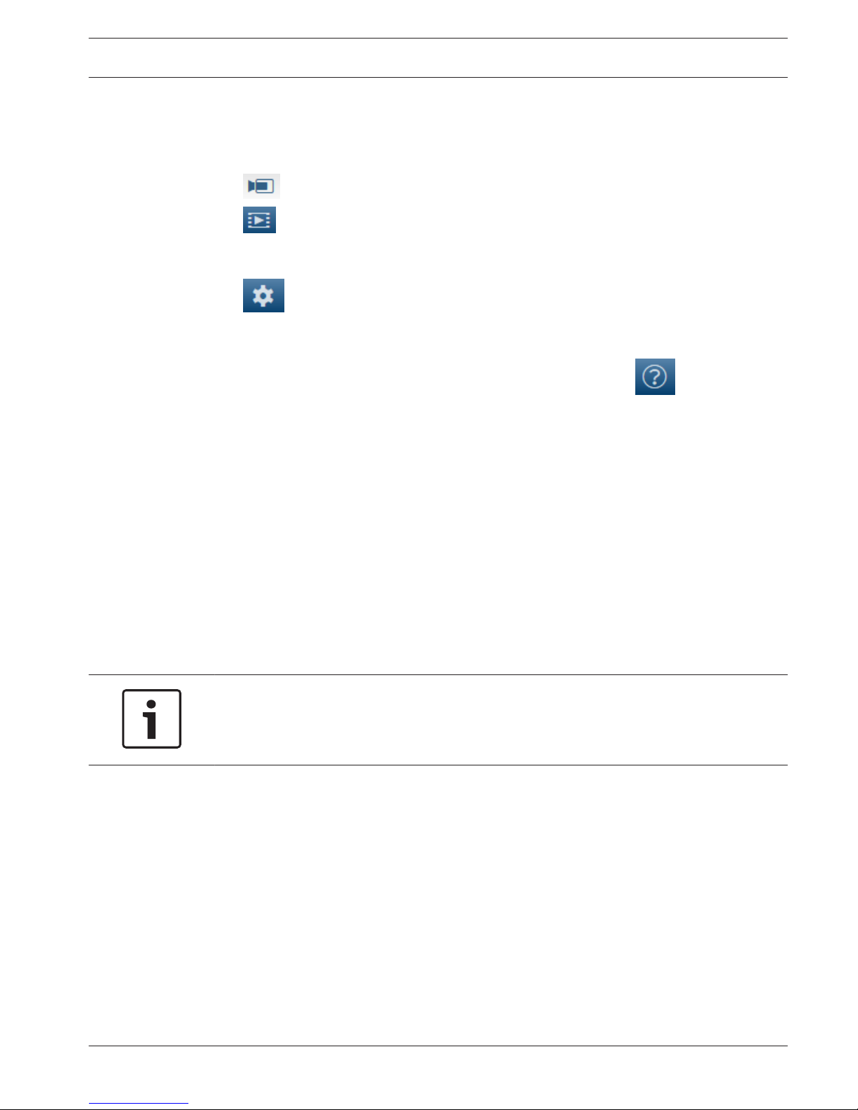
When a connection is established, the Live page is initially displayed. The application bar
displays the following items:
– Live,
– Playback,
This link is only visible if a storage medium has been configured for recording. (With VRM
recording this option is not active.)
– Configuration.
Getting help
To get context sensitive help for a particular page, click the help icon .
Live page
The LIVE page is used to display the live video stream and control the unit.
Playback
The PLAYBACK page is used for playing back recorded sequences.
Configuration
The Configuration page is used to configure the unit and the application interface.
Making Changes
Each configuration screen shows the current settings. You can change the settings by entering
new values or by selecting a predefined value from a list field.
Not every page has a Set button. Changes to pages without a Set button are set immediately.
If a page does show a Set button, you must click the Set button for a change to take effect.
Notice!
Save each change with the associated Set button.
Clicking the Set button saves the settings only in the current field. Changes in any other fields
are ignored.
Some changes only take effect after the unit is rebooted. In this case, the Set button changes
to Set and Reboot.
1. Make the desired changes.
2. Click the Set and Reboot button. The camera reboots and the changed settings are
activated.
All settings are backed up in camera memory so they are not lost even if the power fails. The
exception is the time settings, which are lost after 1 hour without power if no central time
server is selected.
2
2.1
2.2
2.3
AUTODOME IP 4000 HD / AUTODOME
IP 5000 HD/IR
System overview | en 7
Bosch Security Systems Operation Manual 2016.04 | 0.4 |
Operation via the browser
Live page
After the connection is established, the Live page is initially displayed. It shows the live video
image on the right of the browser window. Depending on the configuration, various text
overlays may be visible on the live video image.
Other information may also be shown next to the live video image. The items shown depend
on the settings on the 'Live' functions page.
Connection
Stream 1
Select this option to display stream 1 of the camera.
Stream 2
Select this option to display stream 2 of the camera.
M-JPEG
Select this option to display the M-JPEG stream of the camera.
PTZ
Pan and tilt
To control the pan and tilt of PTZ cameras:
1. Click and hold the up or down arrows to tilt.
2. Click and hold the left or right arrows to pan.
3. Click and hold the center area to control both.
Move the mouse cursor over the video image; additional options for controlling peripherals are
displayed with the mouse cursor.
Click to focus near.
Click to focus far.
Prepositions
The camera displays Preposition 1 through Preposition 6. Select the appropriate preposition
to view the video image for that preposition/scene. In the lower left of the video image, the
OSD displays the Camera number (title), the Preposition/Scene number, and the Preposition/
Scene number stored.
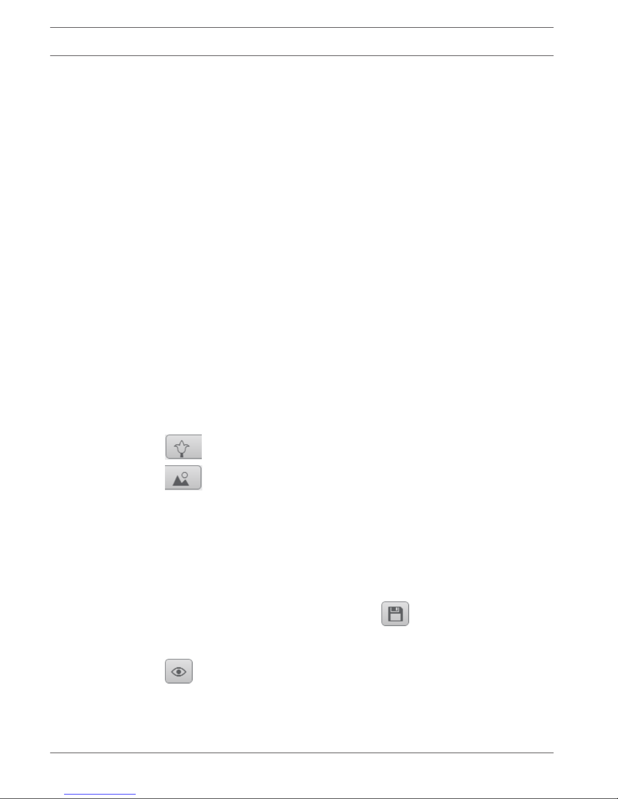
Below the list of prepositions/scenes is a drop-down list showing the stored prepositions/
scenes.
Select the appropriate preposition (1 through 6). Click
to store the preposition.
Note: If the preposition is already stored, a dialog box displays the message, “Overwrite
current preposition?” Click OK to overwrite, or click Cancel to cancel the operation.
Click to display the selected preposition in the video image.
3
3.1
3.1.1
3.1.2
3.1.3
8 en | Operation via the browser
AUTODOME IP 4000 HD / AUTODOME
IP 5000 HD/IR
2016.04 | 0.4 | Operation Manual Bosch Security Systems

AUX Control
Show preposition
Click this button to display a preposition.
Set preposition
Click this button to set a preposition.
AUX on
Click this button to activate an AUX command.
AUX off
Click this button to deactivate an AUX command.
Digital I/O
Input 1
This parameter identifies the first alarm input.
Input 2
This parameter identifies the second alarm input.
Output 1
Click the checkmark icon to enable the output. The checkmark becomes green.
Special Functions
Tour A / Tour B
Click one of these buttons to start the continuous playback of a recorded (guard) tour. A
recorded tour saves all manual camera movements made during the recording, including its
rate of pan, tilt and zoom speeds, and other lens setting changes.
To stop a tour, click a directional control in the View Control tab.
Find home
Click this button to trigger the camera to seek its home position. The OSD displays the
message, “OSD: Finding Home Position.”
Focus
Click this button to activate the Auto Focus mode on the camera.
The OSD displays the message, “OSD: Camera [number] / Auto Focus: ONE PUSH.”
Nightmode
Click this button to activate/deactivate night mode for the camera. After a few seconds, the
camera switches modes.
Recording status
The hard drive icon below the live camera image changes during an automatic recording.
The icon lights up and displays a moving graphic to indicate a running recording. If no
recording is taking place, a static icon is displayed.
Saving snapshots
Individual images from the displayed live video stream can be saved locally in JPEG format on
the computer's hard drive.
– Click the photo camera icon to save a single image.
– The storage location depends on the configuration of the camera.
3.1.4
3.1.5
3.1.6
3.1.7
3.1.8
AUTODOME IP 4000 HD / AUTODOME
IP 5000 HD/IR
Operation via the browser | en 9
Bosch Security Systems Operation Manual 2016.04 | 0.4 |
Recording live video
Video sequences from the displayed live video stream can be saved locally on the computer's
hard drive. The sequences are recorded at the resolution specified in the encoder
configuration. The storage location depends on the configuration of the camera.
1. Click the recording icon
to record video sequences.
– Saving begins immediately. The red dot on the icon indicates that a recording is in
progress.
2. Click the recording icon again to stop recording.
Full-screen display
Click the full-screen icon to view the selected stream in full-screen mode; press Esc
on the keyboard to return to the normal viewing window.
Audio communication
Audio can be sent and received via the Live page if the unit and the computer support audio.
1. Press and hold the F12 key on the keyboard to send an audio signal to the unit.
2. Release the key to stop sending audio.
All connected users receive audio signals sent from the unit but only the user who first
pressed the F12 key can send audio signals; others must wait for the first user to release the
key.
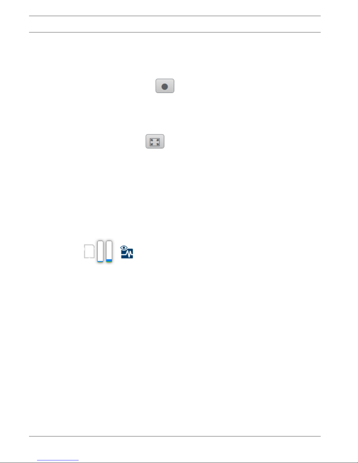
Storage, CPU and network status
When accessing the unit with a browser, the local storage, processor and network status icons
are shown in the upper right of the window.
When a local storage card is available, the memory card icon changes color (green, orange or
red) to indicate the local storage activity. If you hover over this icon with the mouse the
storage activity is shown as a percentage.
If you hover over the middle icon, the CPU load is shown.
If you hover over the right-hand icon, the network load is shown.
This information can help with problem solving or when fine tuning the unit. For example:
– if the storage activity is too high, change the recording profile,
– if the CPU load is too big, change the VCA settings,
– if the network load is too big, change the encoder profile to reduce bitrate.
3.1.9
3.1.10
3.1.11
3.1.12
10 en | Operation via the browser
AUTODOME IP 4000 HD / AUTODOME
IP 5000 HD/IR
2016.04 | 0.4 | Operation Manual Bosch Security Systems
Status icons
Various overlays in the video image provide important status information. The overlays provide
the following information:
Decoding error
The frame might show artifacts due to decoding errors.
Alarm flag
Indicates that an alarm has occurred.
Communication error
A communication error, such as a connection failure to the storage medium, a protocol
violation or a timeout, is indicated by this icon.
Gap
Indicates a gap in the recorded video.
Watermark valid
The watermark set on the media item is valid. The color of the check mark changes according
to the video authentication method that has been selected.
Watermark invalid
Indicates that the watermark is not valid.
Motion alarm
Indicates that a motion alarm has occurred.
Storage discovery
Indicates that recorded video is being retrieved.
Playback
Click Playback in the application bar to view, search or export recordings. This link is
only visible if a direct iSCSI or memory card has been configured for recording. (With VRM
recording this option is not active.)
The panel on the left has four groups:
– Connection
– Search
– Export
– Track list
Selecting the recording stream
On the left side of the browser, expand the Connection group if necessary.
To view a video input channel:
1. Click the Video Input to see the options.
2. Select the video channel you wish to view.
To view a circular or dewarped image for the full image circle:
3.1.13
3.2
3.2.1
AUTODOME IP 4000 HD / AUTODOME
IP 5000 HD/IR
Operation via the browser | en 11
Bosch Security Systems Operation Manual 2016.04 | 0.4 |

1. Click the Dewarping arrow to see the options.
2. Select E-PTZ or Off.
To view a recording stream:
1. Click the Recording arrow to see the options.
2. Select recording stream 1 or 2.
Searching for recorded video
On the left side of the browser, expand the Search group if necessary.
1. To limit the search to a particular time range, enter the start and stop date and times.
2. Select an option from the drop-down box to define a search parameter.
3. Click Start Search.
4. The results are shown.
5. Click a result to play it back.
6. Click Back to define a new search.
Exporting recorded video
On the left side of the browser, expand the Export group if necessary.
1. Select a track in the track list or in the search results.
2. The start and stop date and time are filled-in for the selected track. If required, change
the times.
3. In the Time lapse drop-down box, select the original or a condensed speed.
4. In the Location drop-down box, select a target.
5. Click Export to save the video track.
Note:
The target server address is set on the Network / Accounts page.
Controlling playback
The time bar below the video image allows quick orientation. The time interval associated with
the sequence is displayed in the bar in gray. Arrows indicate the position of the image
currently being played back within the sequence.
The time bar offers various options for navigation in and between sequences.
– If required, click in the bar at the point in time at which the playback should begin.
– Change the time interval displayed by clicking the plus or minus icons. The display can
span a range from two months to a few seconds.
– Click the alarm jump buttons to go from one alarm event to the next or to the previous
one. Red bars indicate the points in time where alarms were triggered.
Controls
Control playback by means of the buttons below the video image.
The time code is displayed on the left above the full-screen icon.
The buttons have the following functions:
– Start/Pause playback
– Select the playback speed using the speed regulator
– Jump to start of active sequence or to previous sequence
– Jump to start of the next video sequence in the list
3.2.2
3.2.3
3.2.4
12 en | Operation via the browser
AUTODOME IP 4000 HD / AUTODOME
IP 5000 HD/IR
2016.04 | 0.4 | Operation Manual Bosch Security Systems
General
Identification
Camera name
The camera name makes it easier to identify the remote camera location, in the event of an
alarm for example. It will be displayed in the video screen if configured to do so. The camera
name makes the task of administering cameras in larger video monitoring systems easier, for
example using the BVC or Bosch Video Management Systems Programs.
Enter a unique, unambiguous name for the camera in this field. You can use both lines for this.
Do not use any special characters, for example &, in the name. Special characters are not
supported by the system's internal management.
You can use the second line for entering additional characters; these can be selected from a
table.
1. Click the icon next to the second line. A new window with the character map is opened.
2. Click the required character. The character is inserted into the Result field.
3. In the character map, click the << and >> icons to move between the different pages of
the table, or select a page from the list field.
4. Click the < icon to the right of the Result field to delete the last character, or click the X
icon to delete all characters.
5. Now click the OK button to apply the selected characters to the second line of the
Camera 1 parameters. The window will close.
Camera ID
Each device should be assigned a unique identifier that can be entered here as an additional
means of identification.
Initiator extension
Add text to an initiator name to make identification easier in large iSCSI systems. This text is
added to the initiator name, separated from it by a full stop. (You can see the initiator name in
the System Overview page.)
Password
The camera is generally protected by a password to prevent unauthorized access to the unit.
You can use different authorization levels to limit access.
Notice!
Proper password protection is only guaranteed when all higher authorization levels are also
protected with a password. If a live password is assigned, for example, a service and a user
password must also be set. When assigning passwords, you should therefore always start
from the highest authorization level, service, and use different passwords.
Password
The camera operates with three authorization levels: service, user and live.
The highest authorization level is service. After entering the correct password, you can access
all the functions of the camera and change all configuration settings.
With the user authorization level, you can operate the unit and also control cameras, for
example, but you cannot change the configuration.
The lowest authorization level is live. It can only be used to view the live video image and
switch between the different live image displays.
You can define and change a password for each authorization level if you are logged in as
service or if the unit is not password protected.
4
4.1
4.2
AUTODOME IP 4000 HD / AUTODOME
IP 5000 HD/IR
General | en 13
Bosch Security Systems Operation Manual 2016.04 | 0.4 |
Enter the password for the appropriate authorization level here.
Confirm password
In each case, enter the new password a second time to eliminate typing mistakes.
Notice!
A new password is only saved when you click the Set button. You should therefore click the
Set button immediately after entering and confirming a password.
Date/Time
Date format
Select your required date format.
Device date/Device time
Notice!
Ensure that recording is stopped before synching to the PC.
If there are multiple devices operating in your system or network, it is important to
synchronize their internal clocks. For example, it is only possible to identify and correctly
evaluate simultaneous recordings when all units are operating on the same time.
1. Enter the current date. Since the unit time is controlled by the internal clock, there is no
need to enter the day of the week – it is added automatically.
2. Enter the current time or click the Sync to PC button to copy your computer's system
time to the camera.
Note: It is important that the date/time is correct for recording. An incorrect date/time setting
could prevent correct recording.
Device time zone
Select the time zone in which your system is located.
Daylight saving time
The internal clock can switch automatically between normal and daylight saving time (DST).
The unit already contains the data for DST switch-overs up to the year 2018. You can use
these data or create alternative time saving data if required.
Notice!
If you do not create a table, there will be no automatic switching. When changing and clearing
individual entries, remember that two entries are usually related to each other and dependent
on one another (switching to summer time and back to normal time).
1. First check whether the correct time zone is selected. If it is not correct, select the
appropriate time zone for the system, and click the Set button.
2. Click the Details button. A new window will open and you will see the empty table.
3. Select the region or the city that is closest to the system's location from the list field
below the table.
4. Click the Generate button to generate data from the database in the unit and enter it into
the table.
5. Make changes by clicking an entry in the table. The entry is selected.
6. Clicking the Delete button will remove the entry from the table.
4.3
14 en | General
AUTODOME IP 4000 HD / AUTODOME
IP 5000 HD/IR
2016.04 | 0.4 | Operation Manual Bosch Security Systems

7. Select other values from the list fields below the table to change the entry. Changes are
made immediately.
8. If there are empty lines at the bottom of the table, for example after deletions, you can
add new data by marking the row and selecting required values from the list fields.
9. Now click the OK button to save and activate the table.
Time server IP address
The camera can receive the time signal from a time server using various time server protocols,
and then use it to set the internal clock. The unit polls the time signal automatically once every
minute.
Enter the IP address of a time server here.
Time server type
Select the protocol that is supported by the selected time server. Preferably, you should
select the SNTP server as the protocol. This supports a high level of accuracy and is required
for special applications and subsequent function extensions.
Select Time server for a time server that works with the protocol RFC 868.
Display Stamping
Various overlays or “stamps” in the video image provide important supplementary information.
These overlays can be enabled individually and are arranged on the image in a clear manner.
After you set all necessary parameters, click the View Control link to see how the stamping
appears on the LIVE page.
Camera name stamping
This field sets the position of the camera name overlay. It can be displayed at the Top, at the
Bottom or at a position of your choice that you can then specify using the Custom option. Or
it can be set to Off for no overlay information.
1. Select the desired option from the list.
2. If you select the Custom option, additional fields are displayed where you can specify the
exact position (Position (XY)).
3. In the Position (XY) fields, enter the values for the desired position.
Logo
Click Choose File to select a file. Heed the restrictions for file format, logo size, and color
depth. Click Upload to load the file to the camera.
If no logo is selected, Configuration displays the message, “No file chosen.”
Logo position
Select the position for the logo on the OSD: Left or Right.
Select Off (the default value) to disable logo positioning.
Time stamping
This field sets the position of the time overlay. It can be displayed at the Top, at the Bottom or
at a position of your choice that you can then specify using the Custom option. Or it can be
set to Off for no overlay information.
1. Select the desired option from the list.
2. If you select the Custom option, additional fields are displayed where you can specify the
exact position (Position (XY)).
3. In the Position (XY) fields, enter the values for the desired position.
Display milliseconds
If necessary, you can also display milliseconds. This information can be useful for recorded
video images; however, it does increase the processor's computing time. Select Off if you do
not need to display milliseconds.
4.4
AUTODOME IP 4000 HD / AUTODOME
IP 5000 HD/IR
General | en 15
Bosch Security Systems Operation Manual 2016.04 | 0.4 |

Alarm mode stamping
Select On to display a text message overlay in the image in the event of an alarm. It can be
displayed at a position of your choice that you can then specify using the Custom option. Or it
can be set to Off for no overlay information.
1. Select the desired option from the list.
2. If you select the Custom option, additional fields are displayed where you can specify the
exact position (Position (XY)).
3. In the Position (XY) fields, enter the values for the desired position.
Alarm message
Enter the message to be displayed in the image in the event of an alarm. The maximum text
length is 31 characters.
Title OSD
Select On to continuously display sector or shot title overlays in the image. Select Momentary
to display sector or shot title overlays for a few seconds. OSD titles can be displayed at a
position of your choice, or it can be set to Off for no overlay information.
1. Select the desired option from the list.
2. Specify the exact position (Position (XY)).
3. In the Position (XY) fields, enter the values for the desired position.
Camera OSD
Select On to momentarily display camera response information, such as Digital Zoom, Iris
open/close, and Focus near/far overlays in the image. Select Off to display no information.
1. Select the desired option from the list.
2. Specify the exact position (Position (XY)).
3. In the Position (XY) fields, enter the values for the desired position.
Transparent background
Check this box to make the stamp on the image transparent.
Video authentication
Select a method for verifying the integrity of the video in the Video authentication drop-down
box.
If you select Watermarking all images are marked with an icon. The icon indicates if the
sequence (live or saved) has been manipulated.
If you want to add a digital signature to the transmitted video images to ensure their integrity,
select one of the cryptographic algorithms for this signature.
Enter the interval (in seconds) between insertions of the digital signature.
Signature intervals
Select the interval (in seconds) for the signature.
GB/T 28181
This page allows you to set the parameters for conformance to the GB/T 28181 national
standard “Security and protection video monitoring network system for information transport,
switch and control”. This standard is specifically for China.
Enable
Select this checkbox to enable the system to use the other parameters on this page in
accordance with the GB/T 28181 national standard.
H.264 elementary stream
Select this checkbox to select or to enable the H.264 elementary stream.
Registration timeout
Enter a value (in milliseconds) for the registration timeout. The default is 3600.
4.5
16 en | General
AUTODOME IP 4000 HD / AUTODOME
IP 5000 HD/IR
2016.04 | 0.4 | Operation Manual Bosch Security Systems

Heartbeat timeout
Enter the value (in seconds) for the heartbeat timeout. The default is 15.
Server ID
Enter the ID of the server.
Server IP address
Enter the server IP address.
Device ID
Enter the ID of the device.
Device port
Enter the number of the device port. The default is 5060.
Password
Enter the appropriate password.
Alarm device ID
Enter the ID of the alarm device.
AUTODOME IP 4000 HD / AUTODOME
IP 5000 HD/IR
General | en 17
Bosch Security Systems Operation Manual 2016.04 | 0.4 |
Web Interface
Appearance
Website language
Select the language for the user interface here.
Company logo
Enter the path to a suitable graphic if you want to replace the manufacturer's logo. The image
file can be stored on a local computer, in the local network or at an Internet address.
Device logo
Enter the path to a suitable graphic if you want to replace the product name. The image file
can be stored on a local computer, in the local network or at an Internet address.
Notice!
If you want to use the original graphics again, simply delete the entries in the Company logo
and Device logo fields.
Show overlay icons
Select this checkbox to show overlay icons on the live video image.
JPEG size
You can specify the size of the JPEG image on the LIVE page. Options are Small, Medium,
Large, 720p, 1080p, and “Best possible” (default).
JPEG interval
You can specify the interval at which the individual images should be generated for the MJPEG image on the LIVE page.
JPEG quality
You can specify the quality at which the JPEG images appear on the LIVE page.
LIVE Functions
On this page you can adapt the functions on the LIVE page to your requirements. You can
choose from a variety of different options for displaying information and controls.
1. Check the box for the items that are to be made available on the LIVE page. The selected
items are indicated by a check mark.
2. Check whether the required functions are available on the LIVE page.
Transmit audio
You can only select this option if audio transmission is actually switched on (see Audio).The
audio signals are sent in a separate data stream parallel to the video data, and so increase the
network load. The audio data are encoded according to G.711 and require an additional
bandwidth of approx. 80 kbps per connection in each direction.
Show alarm inputs
The alarm inputs are displayed next to the video image as icons along with their assigned
names. If an alarm is active, the corresponding icon changes color.
Show alarm outputs
Alarm outputs are shown next to the video image as icons, along with their assigned names. If
the alarm output is active, the corresponding icon changes color.
Allow snapshots
Here you can specify whether the icon for saving individual images (snapshots) should be
displayed below the live image. Individual images can only be saved if this icon is visible.
5
5.1
5.2
18 en | Web Interface
AUTODOME IP 4000 HD / AUTODOME
IP 5000 HD/IR
2016.04 | 0.4 | Operation Manual Bosch Security Systems
 Loading...