

Bosch 0 607 161 101, 0 607 161 100, 0 607 161 102, 0 607 161 500, 0 607 161 103 Series Manual
...
0 607 161 1..
0 607 161 5..
Production Tools
www.boschproductiontools.com
13
13
14
17
17
18
20
15
16
19
8
0 607 161 1..
28
6
3
5
4
A
23
22
21
27
30
31
32
33
10
4
29
B
3
4
6
5
24
6
25
0 607 161 5..
15
2
1
C
23
22
3
21
13
14
11
12
16
17
17
13
19
18
20
D
4
6
5
24
6
25
10
9
3
4
8
5
6
7
E
26
11

1 ALLGEMEINE SICHERHEITSHINWEISE
FÜR DRUCKLUFTGERÄTE
Lesen und beachten Sie alle
Hinweise.
folgenden Sicherheitshinweise können elektrischer Schock, Brandgefahr oder ernsthafte
Verletzungen die Folge sein.
Bewahren Sie die Sicherheitshinweise gut auf.
Der im folgenden Text verwendete Begriff „Druckluftgerät“ oder „Gerät“ bezieht sich auf die in dieser Bedienungsanleitung genannten Druckluftgeräte.
Arbeitsplatz
Halten Sie Ihren Arbeitsplatz sauber und gut beleuchtet. Unordnung am Arbeitsplatz und unbeleuch-
tete Arbeitsbereiche können zu Unfällen führen.
Arbeiten Sie mit dem Gerät nicht in explosionsgefährdeter Umgebung, in der sich brennbare
Flüssigkeiten, Gase oder Staub befinden. Beim
Bearbeiten des Werkstücks können Funken entstehen, die den Staub oder die Dämpfe entzünden.
Halten Sie Zuschauer, Kinder und Besucher von
Ihrem Arbeitsplatz fern, wenn Sie das Gerät benutzen. Bei Ablenkung durch andere Personen kön-
nen Sie die Kontrolle über das Gerät verlieren.
Sicherheit von Druckluftgeräten
Verwenden Sie Druckluft der Qualitätsklasse 5
nach DIN ISO 8573-1 und eine separate Wartungseinheit nahe am Gerät. Die zugeführte Druck-
luft muss frei von Fremdkörpern und Feuchtigkeit sein,
um das Gerät vor Beschädigung, Verschmutzung und
Rostbildung zu schützen.
Kontrollieren Sie Anschlüsse und Versorgungsleitungen. Sämtliche Wartungseinheiten, Kupplungen
und Schläuche müssen in Bezug auf Druck und Luftmenge entsprechend den Gerätekennwerten ausgelegt sein. Zu geringer Druck beeinträchtigt die Funktion
des Gerätes, zu hoher Druck kann zu Sachschäden
und zu Verletzungen führen.
Schützen Sie die Schläuche vor Knicken, Verengungen, Lösungsmitteln und scharfen Kanten.
Halten Sie die Schläuche fern von Hitze, Öl und
rotierenden Teilen. Ersetzen Sie einen beschädigten Schlauch unverzüglich. Eine schadhafte
Versorgungsleitung kann zu einem herumschlagenden
Druckluftschlauch führen und kann Verletzungen verursachen. Aufgewirbelter Staub oder Späne können
schwere Augenverletzungen hervorrufen.
Achten Sie darauf, dass Schlauchschellen immer
fest angezogen sind. Nicht fest gezogene oder
beschädigte Schlauchschellen können die Luft unkontrolliert entweichen lassen.
Bei Nichtbeachtung der
Sicherheit von Personen
Seien Sie aufmerksam, achten Sie darauf, was
Sie tun und gehen Sie mit Vernunft an die Arbeit
mit dem Gerät. Gebrauchen Sie das Gerät nicht,
wenn Sie müde sind oder unter dem Einfluss von
Drogen, Alkohol oder Medikamenten stehen. Ein
Moment der Unaufmerksamkeit beim Gebrauch des
Gerätes kann zu ernsthaften Verletzungen führen.
Tragen Sie Schutzkleidung und immer eine
Schutzbrille. Das Tragen von Sicherheitskleidung,
wie Staubschutzmaske, rutschfeste Sicherheitsschuhe, Helme oder Gehörschutz, je nach Art und Gebrauch des Gerätes, verringert das Risiko von Verletzungen.
Vermeiden Sie die unbeabsichtigte Inbetriebnahme des Gerätes. Vergewissern Sie sich, dass der
Ein-Aus-Schalter in der Position „Aus“ ist, bevor
Sie das Gerät an die Luftversorgung anschließen. Wenn Sie beim Tragen des Gerätes den Finger
am Ein-Aus-Schalter haben oder das Gerät an die
Luftversorgung anschließen, während der Ein-AusSchalter in der Position „Ein“ ist, kann dies zu Unfällen
führen.
Entfernen Sie Einstellwerkzeuge, bevor Sie das
Gerät in Betrieb nehmen. Ein Einstellwerkzeug, das
sich in einem drehenden Geräteteil befindet, kann zu
Verletzungen führen.
Überschätzen Sie sich nicht. Sorgen Sie für einen
sicheren Stand, und halten Sie jederzeit das
Gleichgewicht. Ein sicherer Stand und geeignete
Körperhaltung lassen Sie das Gerät in unerwarteten
Situationen besser kontrollieren.
Tragen Sie geeignete Arbeitskleidung. Tragen
Sie keine weite Kleidung oder Schmuck. Halten
Sie Haare, Kleidung und Handschuhe fern von
sich bewegenden Geräteteilen. Lockere Kleidung,
Schmuck und lange Haare können von sich bewegenden Teilen erfasst werden.
Wenn Staubabsaug- und -auffangeinrichtungen
montiert werden können, vergewissern Sie sich,
dass diese angeschlossen sind und richtig verwendet werden. Das Verwenden dieser Einrichtun-
gen verringert Gefährdungen durch Staub.
Atmen Sie die Abluft nicht direkt ein. Vermeiden
Sie es, die Abluft in die Augen zu bekommen. Die
Abluft des Druckluftgerätes kann Wasser, Öl, Metallpartikel oder Verunreinigungen aus dem Kompressor
enthalten. Dies kann Gesundheitsschäden verursachen.
3 609 929 935 • (03.10) T
Deutsch–1

Sorgfältiger Umgang mit und Gebrauch von
Druckluftgeräten
Benutzen Sie Spannvorrichtungen oder einen
Schraubstock, um das Werkstück festzuhalten.
Wenn Sie das Werkstück mit der Hand festhalten oder
an den Körper drücken, können Sie das Gerät nicht sicher bedienen.
Überlasten Sie das Gerät nicht. Verwenden Sie
für Ihre Arbeit das dafür bestimmte Gerät. Mit
dem geeigneten Gerät arbeiten Sie besser und sicherer im angegebenen Leistungsbereich.
Gebrauchen Sie kein Gerät, dessen Ein-AusSchalter defekt ist. Ein Gerät, das sich nicht mehr
ein- oder ausschalten lässt, ist gefährlich und muss repariert werden.
Unterbrechen Sie die Luftversorgung, bevor Sie
Geräteeinstellungen durchführen, Zubehörteile
wechseln und bei längerem Nichtgebrauch. Diese
Vorsichtsmaßnahme verhindert eine unbeabsichtigte
Inbetriebnahme des Gerätes.
Bewahren Sie ungenutzte Druckluftgeräte außerhalb der Reichweite von Kindern auf. Lassen
Sie Personen das Druckluftgerät nicht benutzen,
die mit diesem nicht vertraut sind oder diese Anleitung nicht gelesen haben. Druckluftgeräte sind
gefährlich, wenn sie von unerfahrenen Personen benutzt werden.
2 GERÄTESPEZIFISCHE SICHERHEITSHINWEISE
FÜR BOHRMASCHINEN
Vermeiden Sie den Kontakt mit einer spannungsführenden Leitung.
Das Gerät ist nicht isoliert, und der
Kontakt mit einer spannungsführenden Leitung kann
zu einem elektrischen Schlag führen.
Verwenden Sie geeignete Suchgeräte, um verborgene Versorgungsleitungen aufzuspüren,
oder ziehen Sie die örtliche Versorgungsgesellschaft hinzu. Kontakt mit spannungsführenden Lei-
tungen kann zu Feuer und elektrischem Schlag führen.
Beschädigung einer Gasleitung kann zur Explosion
führen. Eindringen in eine Wasserleitung verursacht
Sachbeschädigung.
Unterbrechen Sie alle Sicherungen oder Schutzschalter, die den Arbeitsbereich speisen, bevor
Sie in diesem Bereich bohren, schneiden oder etwas befestigen. So schließen Sie elektrischen
Schlag aus.
Halten Sie das Gerät gut fest und bringen Sie Ihren Körper und Ihre Arme in eine Stellung, die
den Rückschlagkräften standhalten kann. Rück-
schlagkräfte können entstehen, wenn das Einsatzwerkzeug klemmt oder hakt. Der Motor kommt dabei
zum Stillstand, ohne dass das Gerät Schaden nimmt.
Pflegen Sie Ihr Druckluftgerät mit Sorgfalt. Kontrollieren Sie, ob bewegliche Geräteteile einwandfrei funktionieren und nicht klemmen, und
ob Teile gebrochen oder beschädigt sind, die die
Funktionsweise des Druckluftgerätes beeinflussen könnten. Lassen Sie beschädigte Geräteteile
reparieren, bevor Sie das Gerät wieder in Betrieb
nehmen. Viele Unfälle haben ihre Ursachen in
schlecht gewarteten Geräten.
Halten Sie die Einsatzwerkzeuge sauber. Sorg-
fältig gepflegte Einsatzwerkzeuge lassen sich leichter
führen und sind besser zu kontrollieren.
Verwenden Sie Druckluftgeräte, Zubehör, Einsatzwerkzeuge usw. entsprechend diesen Anweisungen und so wie es für diesen speziellen
Gerätetyp vorgeschrieben ist. Berücksichtigen
Sie dabei die Arbeitsbedingungen und die auszuführende Tätigkeit. Der Gebrauch des Druckluftge-
rätes für andere als die vorgesehenen Anwendungen
kann zu gefährlichen Situationen führen.
Service
Lassen Sie Ihr Druckluftgerät nur von qualifiziertem Fachpersonal und nur mit Original-Ersatzteilen reparieren. Damit wird sichergestellt, dass die Si-
cherheit des Druckluftgerätes erhalten bleibt.
Schalten Sie das Gerät sofort aus, wenn das Einsatzwerkzeug blockiert. Seien Sie auf hohe
Reaktionsdrehmomente gefasst, die einen
Rückschlag verursachen. Das Einsatzwerkzeug
blockiert, wenn:
– das Gerät überlastet wird,
– es im zu bearbeitenden Werkstoff verkantet oder
– es mit der Spitze durch den zu bearbeitenden
Werkstoff hindurchgeht.
Verwenden Sie nur einwandfreie, nicht verschlissene Einsatzwerkzeuge. Defekte Einsatzwerkzeuge
können beispielsweise brechen und zu Verletzungen
und Sachschäden führen.
Achten Sie beim Einsetzen eines Einsatzwerkzeugs darauf, dass der Schaft des Einsatzwerkzeugs fest in der Werkzeugaufnahme sitzt. Wenn
der Schaft des Einsatzwerkzeugs nicht tief genug in
die Werkzeugaufnahme gesteckt wird, kann das Einsatzwerkzeug wieder herausrutschen und nicht mehr
kontrolliert werden.
Schalten Sie das Gerät nie ein, während Sie es
tragen. Eine rotierende Werkzeugaufnahme kann
Kleidung oder Haare aufwickeln und zu Verletzungen
führen.
3 609 929 935 • (03.10) T
Deutsch–2
Wenn Sie das Gerät in einer Aufhänge- oder Einspannvorrichtung betreiben wollen, achten Sie
darauf, es erst in der Vorrichtung zu befestigen,
bevor Sie es an die Luftversorgung anschließen.
Dadurch vermeiden Sie, es unbeabsichtigt in Betrieb
zu nehmen.
Kontrollieren Sie regelmäßig den Zustand des Aufhängebügels und der Haken in der Aufhängevorrichtung.
Der beim Schmirgeln, Sägen,
Schleifen, Bohren und ähnlichen Tätigkeiten entstehende
Staub kann krebserzeugend, fruchtschädigend
Einige der in diesen Stäuben enthaltenen Stoffe sind:
– Blei in bleihaltigen Farben und Lacken;
– kristalline Kieselerde in Ziegeln, Zement und ande-
ren Maurerarbeiten;
– Arsen und Chromat in chemisch behandeltem
Holz.
Das Risiko einer Erkrankung hängt davon ab, wie oft
Sie diesen Stoffen ausgesetzt sind. Um die Gefahr zu
reduzieren, sollten Sie nur in gut belüfteten Räumen
mit entsprechender Schutzausrüstung arbeiten (z.B.
mit speziell konstruierten Atemschutzgeräten, die
auch kleinste Staubpartikel herausfiltern).
oder erbgutverändernd wirken.
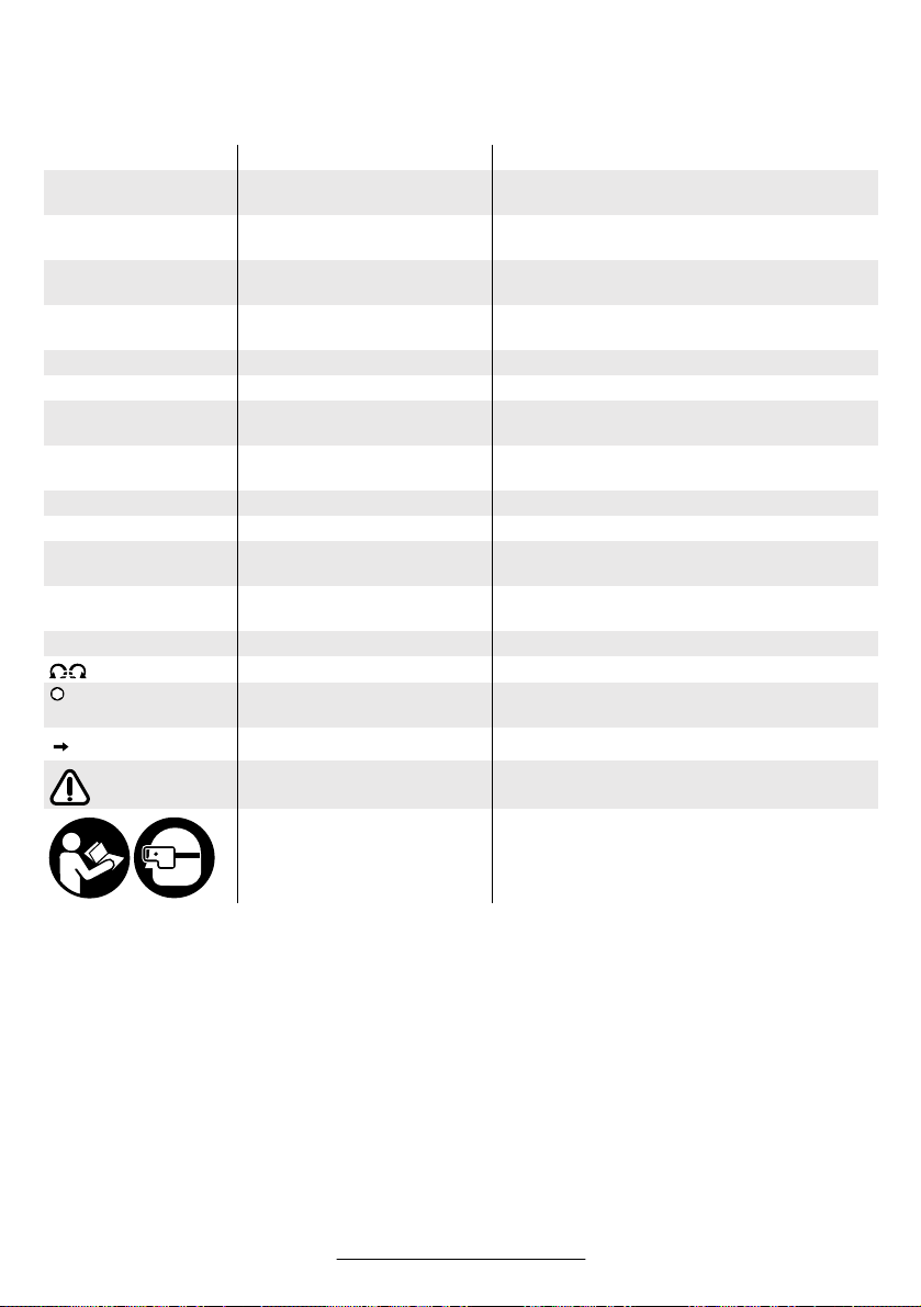
SYMBOLE
Wichtiger Hinweis: Einige der nachfolgenden Symbole können für den Gebrauch Ihres Gerätes von Bedeutung
sein. Prägen Sie sich bitte die Symbole und ihre Bedeutung ein. Die richtige Interpretation der Symbole hilft Ihnen, das Gerät besser und sicherer zu gebrauchen.
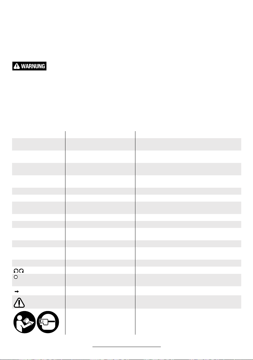
Symbol Name Bedeutung
W
Hp
Nm
ft-lbs
kg
lbs
mm
in
min/s Minuten/Sekunden Zeitspanne, Dauer
bar/psi bar/pounds per square inch Luftdruck
l/s
cfm
°C/°F Grad Celsius/Grad Fahrenheit Temperatur
dB Dezibel Bes. Maß der relativen Lautstärke
Ø Durchmesser z.B. Schraubendurchmesser,
-1
/n
min
0
.../min Umdrehungen oder Bewegun-
0 Position: Aus Keine Geschwindigkeit, kein Drehmoment
/ ■ /UNF Innensechskant/Außenvierkant/
Watt
Leistung
Horsepower
Newtonmeter
Energieeinheit, Drehmoment
foot-pounds
Kilogramm
Masse, Gewicht
pounds
Millimeter
Länge
inches
Liter pro Sekunde
Luftverbrauch
cubic feet/minute
Schleifscheibendurchmesser etc.
Drehzahl Drehzahl im Leerlauf
Umdrehungen, Schläge, Kreisbahnen etc.
gen pro Minute
pro Minute
Linkslauf/Rechtslauf Drehrichtung
Art der Werkzeugaufnahme
unifiziertes National-Feingewinde
Pfeil Handlung in Pfeilrichtung ausführen.
Warnhinweis Warnt den Benutzer vor Gefahren.
3 609 929 935 • (03.10) T
Gebotszeichen Gibt Hinweise auf die korrekte Handhabung,
z.B. Bedienungsanleitung lesen oder Schutzbrille
aufsetzen.
Deutsch–3

3 FUNKTIONSBESCHREIBUNG
Bitte klappen Sie die Ausklappseite mit
der Darstellung des Gerätes auf, und
lassen Sie diese Seite aufgeklappt,
während Sie die Bedienungsanleitung
lesen.
Bestimmungsgemäßer Gebrauch
Das Gerät ist bestimmt zum Bohren in Metall, Holz,
Keramik und Kunststoff.
Geräusch-/Vibrationsinformation
Messwerte für Geräusch ermittelt entsprechend EN
ISO 15 744. Messunsicherheit 3 dB(A).
Messwerte für Vibration ermittelt entsprechend EN
28 662 und EN ISO 8662.
Der A-bewertete Schalldruckpegel des Gerätes beträgt typischerweise 76 dB(A). Der Geräuschpegel
beim Arbeiten kann 85 dB(A) überschreiten.
Gehörschutz tragen!
Die Hand-Arm-Beschleunigung ist typischerweise
niedriger als 2,5 m/s
Konformitätserklärung
Wir erklären in alleiniger Verantwortung, dass dieses
Produkt mit den folgenden Normen oder normativen
Dokumenten übereinstimmt: EN 792, gemäß den Bestimmungen der Richtlinie 98/37/EG.
Dr. Egbert Schneider
Senior Vice President
Engineering
Robert Bosch GmbH, Geschäftsbereich Elektrowerkzeuge
2
. Messunsicherheit K = 1,2 m/s
Dr. Eckerhard Strötgen
Head of Product
Certification
1
2
3
4
5
6
Geräteelemente
Die Nummerierung der Geräteelemente bezieht sich
auf die Darstellung des Gerätes auf der Grafikseite.
Zusatzgriff*
Aufhängebügel mit Abstützmöglichkeit*
Anschlussstutzen am Lufteinlass
Schlauchnippel
Zuluftschlauch*
Schlauchschellen*
Abluftschlauch (zentral) für Pistolenausführung*
Luftaustritt mit Schalldämpfer
Ein-Aus-Schalter
Einspannbereich
(Spannhals-Ø siehe Gerätekennwerte )
Schlüsselfläche an der Bohrspindel
Bohrspindel
Einsatzwerkzeug (HSS-R-Metallbohrer)*
Bohrfutterschlüssel*
Hülse*
Zahnkranzbohrfutter*
Werkzeugaufnahme*
Vordere Hülse*
19 Hintere Hülse*
2
20 Schnellspannbohrfutter*
.
21 Kupplungsnippel*
22 Automatische Schlauchkupplung*
23 Luftaustritt der Wartungseinheit*
24 Schlauchnippel für den Abluftschlauch*
25 Abluftschlauch dezentral*
26 Gabelschlüssel*
27 Hebel
28 Abluftschlauch (zentral)*
29 Schalldämpfer aus Sintermetall am Abluftset*
30 Anschlussstutzen am Abluftset*
31 Abluftset (dezentral)*
32 Dichtring 40 x 2 mm*
33 Aufhängebügel
* Zubehör
Abgebildetes oder beschriebenes Zubehör gehört teilweise nicht zum Lieferumfang.
7
8
9
10
11
12
13
14
15
16
17
18
3 609 929 935 • (03.10) T
Deutsch–4

Gerätekennwerte
Druckluft-Bohrmaschine, gerade Ausführung
Bestellnummer 0 607 161 … … 100 … 101 … 102 … 103
Leerlaufdrehzahl min
Abgabeleistung W
max. Bohr-Ø Stahl mm
Lieferumfang
Schnellspannbohrfutter
Zahnkranzbohrfutter
Drehrichtung
Bohrspindelgewinde 1/2"–20 UNF –2A ● ● ● ●
Schlüsselfläche 11 an der Bohrspindel mm 17 17 17 17
Spannhals-Ø mm 46 46 46 46
Nenndruck bar/psi 6,3/91 6,3/91 6,3/91 6,3 /91
Anschlussgewinde G 1/4" G 1/4" G 1/4" G 1/4"
Lichte Schlauchweite mm 10 10 10 10
Luftverbrauch unter Last l/s
Gewicht (ohne Zubehör) ca. kg
Druckluft-Bohrmaschine, Pistolenform
Bestellnummer 0 607 161 … … 500 … 501 … 502 … 503 … 504 … 505 … 506 … 507
Leerlaufdrehzahl min-12560 1200 800 640 2 560 1 200 800 640
Abgabeleistung WHp400
0,54
max. Bohr-Ø Stahl mm
in85/16"103/8"131/2"131/2"85/16"103/8"131/2"131/2"
Lieferumfang
Schnellspannbohrfutter
Zahnkranzbohrfutter
●
Drehrichtung
Bohrspindelgewinde 1/2"–20 UNF–2A ● ● ● ● ● ● ● ●
Schlüsselfläche 11 an der
Bohrspindel mm 17 17 17 17 17 17 17 17
Spannhals-Ø mm 48 48 48 48 48 48 48 48
Nenndruck bar/psi 6,3/91 6,3/91 6,3/91 6,3 /91 6,3/ 91 6,3/91 6,3/91 6,3/91
Anschlussgewinde G 1/4" G 1/4" G 1/4" G 1/4" G 1/4" G 1/4" G 1/4" G 1/4"
Lichte Schlauchweite mm 10 10 10 10 10 10 10 10
Luftverbrauch unter Last l/s
Gewicht (ohne Zubehör) ca. kg
cfm
lbs
10,5
22,2
1,10
2,4
-1
2560 1200 2560 1200
Hp
0,54
8
400
in
5/16"
–
●
11,0
cfm
23,3
1,10
lbs
400
0,54
–
–
●
10,5
22,2
1,30
2,9
400
0,54
10,5
22,2
1,45
3,2
2,4
0,54
–
●
10,5
22,2
1,45
400
3,2
400
0,54
10
3/8"
–
●
11,0
23,3
1,20
2,6
400
0,54
–
●
●
–
10,5
22,2
1,30
2,9
400
0,54
10,5
22,2
1,50
3,3
400
0,54
5/16"
11,0
23,3
1,30
2,8
●
–
8
●
–
400
0,54
10,5
22,2
1,50
3,3
400
0,54
3/8"
11,0
23,3
1,45
400
0,54
●
–
10,5
22,2
1,60
10
●
–
3,2
●
–
3,5
3 609 929 935 • (03.10) T
Deutsch–5

4 MONTAGE
Aufhänge- und Einspannvorrichtung
Wenn Sie das Gerät in einer Aufhänge- oder Einspannvorrichtung betreiben wollen, achten Sie
darauf, es erst in der Vorrichtung zu befestigen,
bevor Sie es an die Luftversorgung anschließen.
Dadurch vermeiden Sie, es unbeabsichtigt in Betrieb
zu nehmen.
Mit dem Aufhängebügel 33 (Typ 0 607 161 1..) oder 2
(Typ 0 607 161 5..) können Sie das Gerät an einer Aufhängevorrichtung befestigen.
Kontrollieren Sie regelmäßig den Zustand des Aufhängebügels und der Haken in der Aufhängevorrichtung.
Im angegebenen Einspannbereich 10 können Sie das
Gerät in einer Einspannvorrichtung befestigen. Nutzen
Sie möglichst den gesamten Einspannbereich. Je geringer der Einspannbereich, desto stärker wirken die
Spannkräfte.
Überlasten Sie den Einspannbereich nicht, und sorgen
Sie dafür, dass die Einspannvorrichtung das Gerät sicher und fest hält.
Abluftführung
Mit einer Abluftführung können Sie die Abluft durch einen Abluftschlauch von Ihrem Arbeitsplatz wegleiten
und gleichzeitig eine optimale Schalldämpfung erreichen. Zudem verbessern Sie Ihre Arbeitsbedingungen, da Ihr Arbeitsplatz nicht mehr von ölhaltiger Luft
verschmutzt werden kann oder Staub bzw. Späne
aufgewirbelt werden.
Typ 0 607 161 100 – … 103
Stülpen Sie den Abluftschlauch (zentral) 28, der die
Abluft von Ihrem Arbeitsplatz wegleitet, über den Zuluftschlauch 5. Schließen Sie das Gerät dann an die
Luftversorgung an (siehe Abschnitt Anschluss an die
Luftversorgung) und ziehen Sie den Abluftschlauch
(zentral) 28 über den montierten Zuluftschlauch auf
das Geräteende.
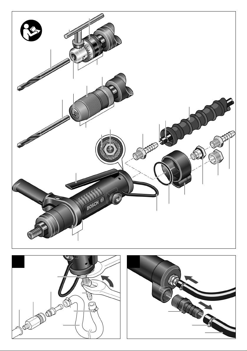
Oder Sie leiten die Abluft in einen Abluftbehälter, indem Sie zunächst das Abluftset (dezentral) 31 befestigen. Achten Sie darauf, dass der Schlauchnippel 4
nicht in den Anschlussstutzen am Lufteinlass 3 eingeschraubt ist und der Dichtring 32 in der Vertiefung zwischen Gehäuse und Abluftset liegt, damit die ausströmende Luft nur zum Abluftschlauch entweichen kann.
Schrauben Sie zunächst den Anschlussstutzen 30 des
Abluftsets fest in den Anschlussstutzen 3 am Lufteinlass und anschließend den Schlauchnippel 4 auf den
Anschlussstutzen 30. Ersetzen Sie den Schalldämpfer
29 am Abluftset durch den Schlauchnippel 24 des Abluftsets (siehe Bild ).
Lockern Sie die Schlauchschelle 6 des Abluftschlauches 25, und befestigen Sie den Abluftschlauch über
dem Schlauchnippel 24 mit der Schlauchschelle, indem Sie diese fest anziehen.
3 609 929 935 • (03.10) T
B
Deutsch–6
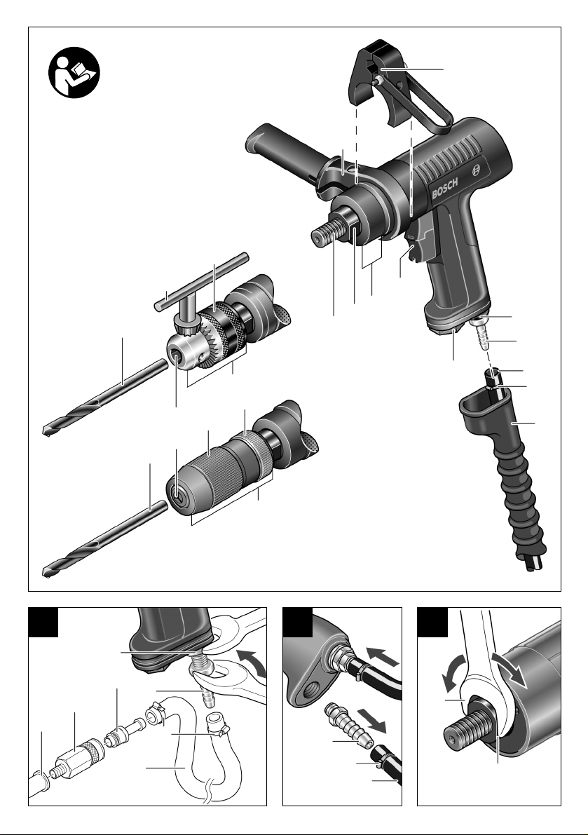
Typ 0 607 161 500 – … 507
Stülpen Sie den Abluftschlauch (zentral) für Pistolenausführung 7, der die Abluft von Ihrem Arbeitsplatz
wegleitet, über den Zuluftschlauch 5. Schließen Sie
das Gerät dann an die Luftversorgung an (siehe Abschnitt Anschluss an die Luftversorgung) und ziehen
Sie den Abluftschlauch (zentral) für Pistolenausführung
7 über den montierten Zuluftschlauch auf das Geräteende.
Oder Sie leiten die Abluft in einen Abluftbehälter, indem Sie den Schalldämpfer am Luftaustritt 8 durch
den Schlauchnippel 24 ersetzen (siehe Bild ).
Lockern Sie die Schlauchschelle 6 des Abluftschlauches 25, und befestigen Sie den Abluftschlauch über
dem Schlauchnippel 24 mit der Schlauchschelle, indem Sie diese fest anziehen.
D
Anschluss an die Luftversorgung
Das Gerät ist für einen Betriebsdruck von 6,3 bar
(91 psi) ausgelegt. Für eine maximale Leistung beträgt
die lichte Schlauchweite 10 mm bei einem Anschlussgewinde von G 1/4". Zur Erhaltung der vollen Leistung
nur Schläuche bis maximal 4 m Länge verwenden.
Die zugeführte Druckluft muss frei sein von Fremdkörpern und Feuchtigkeit, um das Gerät vor Beschädigung, Verschmutzung und Rostbildung zu schützen.
Die Verwendung einer Druckluft-Wartungseinheit ist notwendig.
Diese gewährleistet eine einwandfreie Funktion von
Druckluftwerkzeugen. Beachten Sie die Bedienungsanleitung der Wartungseinheit.
Sämtliche Armaturen, Verbindungsleitungen und
Schläuche müssen dem Druck und der erforderlichen
Luftmenge entsprechend ausgelegt sein.
Verengungen der Zuleitungen, z.B. durch Quetschen,
Knicken oder Zerren, vermeiden!
Prüfen Sie im Zweifelsfall den Druck am Lufteintritt mit
einem Manometer bei eingeschaltetem Gerät.
Anschluss der Luftversorgung an das Gerät
Schrauben Sie den Schlauchnippel 4 in den Anschlussstutzen am Lufteinlass 3 ein (Typ 0 607 161 1.. siehe
A C
Bild , Typ 0 607 161 5.. siehe Bild ).
Um Beschädigungen an innen liegenden Ventilteilen
des Gerätes zu vermeiden, sollten Sie beim Ein- und
Ausschrauben des Schlauchnippels 4 an dem vorstehenden Anschlussstutzen des Lufteinlasses 3 mit einem Gabelschlüssel (22 mm) gegenhalten.
Lockern Sie die Schlauchschellen 6 des maximal 4 m
langen Zuluftschlauches 5, und befestigen Sie den Zuluftschlauch über dem Schlauchnippel 4 mit der
Schlauchschelle, indem Sie diese fest anziehen.
Befestigen Sie den Zuluftschlauch 5 immer erst
am Gerät, dann an der Wartungseinheit.
Stülpen Sie den Zuluftschlauch 5 über den Kupplungsnippel 21 und befestigen Sie den Zuluftschlauch,
indem Sie die Schlauchschelle 6 fest anziehen.
Schrauben Sie in den Luftaustritt der Wartungseinheit
23 eine automatische Schlauchkupplung 22. Automatische Schlauchkupplungen ermöglichen eine schnelle
Verbindung und stellen die Luftzufuhr beim Entkuppeln automatisch ab.
Achten Sie darauf, das Gerät nicht unbeabsichtigt in
Betrieb zu nehmen, wenn Sie den Kupplungsnippel 21
in die Kupplung 22 stecken.
Montage des Bohrfutters
Halten Sie die Bohrspindel 12 an der Schlüsselfläche
11 mit einem passenden Gabelschlüssel fest und
schrauben Sie das Zahnkranzbohrfutter 16 oder das
Schnellspannbohrfutter 20 auf die Bohrspindel 12 auf
(siehe Bild ).
Das Bohrfutter muss mit einem Anzugsdrehmoment
von ca. 30–35 Nm festgezogen werden.
Achten Sie darauf, dass das Bohrfutter fest auf der
Bohrspindel sitzt.
E
Wechsel des Zahnkranzbohrfutters
Verletzungsgefahr! Entfernen Sie vor
dem Abnehmen des Bohrfutters unbedingt die Einsatzwerkzeuge.
Vorsicht! Einsatzwerkzeuge können bei
längerem Betrieb des Gerätes heiß werden. Verwenden Sie Schutzhandschuhe.
Halten Sie die Bohrspindel 12 an der Schlüsselfläche
11 mit einem passenden Gabelschlüssel fest. Stecken
Sie den Bohrfutterschlüssel 14 in eine der drei Bohrungen am Zahnkranzbohrfutter 16 und lösen Sie mit diesem Hebel durch Linksdrehen das Bohrfutter wie eine
Schraube. Ein fest sitzendes Bohrfutter lösen Sie, indem Sie mit einem Sechskant in der Werkzeugaufnahme 17 dagegenhalten.
Wechsel des Schnellspannbohrfutters
Verletzungsgefahr! Entfernen Sie vor
dem Abnehmen des Bohrfutters unbedingt die Einsatzwerkzeuge.
Vorsicht! Einsatzwerkzeuge können bei
längerem Betrieb des Gerätes heiß werden. Verwenden Sie Schutzhandschuhe.
Legen Sie das Gerät auf eine standfeste Unterlage
(z.B. Werkbank). Halten Sie die Bohrspindel 12 an der
Schlüsselfläche 11 mit einem passenden Gabelschlüssel fest und lösen Sie durch Linksdrehen das
Schnellspannbohrfutter 20 von der Bohrspindel. Ein
fest sitzendes Bohrfutter lösen Sie, indem Sie mit einem Sechskant in der Werkzeugaufnahme 17 dagegenhalten.
5 BETRIEB
Werkzeugwechsel
Zahnkranzbohrfutter
Einsatzwerkzeug einsetzen
Drehen Sie die Hülse 15 des Zahnkranzbohrfutters 16
nach links, bis die Werkzeugaufnahme 17 weit genug
geöffnet ist. Setzen Sie das Einsatzwerkzeug 13 in die
Mitte der Werkzeugaufnahme 17 ein und spannen Sie
es mit dem Bohrfutterschlüssel 14 gleichmäßig in allen
drei Bohrungen.
Einsatzwerkzeug entfernen
Vorsicht! Einsatzwerkzeuge können bei
längerem Betrieb des Gerätes heiß werden. Verwenden Sie Schutzhandschuhe.
Drehen Sie die Hülse 15 des Zahnkranzbohrfutters 16
mit Hilfe des Bohrfutterschlüssels 14 nach links, bis
das Einsatzwerkzeug 13 aus der Werkzeugaufnahme
17 entnommen werden kann.
3 609 929 935 • (03.10) T
Deutsch–7
Werkzeugwechsel
Schnellspannbohrfutter
Einsatzwerkzeug einsetzen
Halten Sie die hintere Hülse 19 des Schnellspannbohrfutters 20 fest und öffnen Sie die Werkzeugaufnahme
17 durch Drehen der vorderen Hülse 18 so weit, bis
das Einsatzwerkzeug 13 eingesetzt werden kann.
Zum Spannen des Einsatzwerkzeugs 13 halten Sie die
hintere Hülse 19 fest und drehen die vordere Hülse 18
kräftig zu.
Einsatzwerkzeug entfernen
Vorsicht! Einsatzwerkzeuge können bei
längerem Betrieb des Gerätes heiß werden. Verwenden Sie Schutzhandschuhe.
Halten Sie die hintere Hülse 19 des Schnellspannbohrfutters 20 fest und öffnen Sie die Werkzeugaufnahme
17 durch Drehen der vorderen Hülse 18 so weit, bis
das Einsatzwerkzeug 13 entnommen werden kann.
Inbetriebnahme
Das Gerät arbeitet optimal bei einem Nenndruck von
6,3 bar (91 psi), gemessen bei laufendem Gerät am
Lufteintritt.
Entfernen Sie Einstellwerkzeuge, bevor Sie das
Gerät in Betrieb nehmen. Ein Einstellwerkzeug, das
sich in einem drehenden Geräteteil befindet, kann zu
Verletzungen führen.
Ein-Aus-Schalten
Läuft das Gerät, z.B. nach längerer Ruhezeit, nicht an,
unterbrechen Sie die Luftversorgung und drehen mit
einem passenden Gabelschlüssel 26 an der Schlüsselfläche 11 den Motor mehrmals durch (siehe
E
Bild ). Dadurch werden Adhäsionskräfte beseitigt.
Typ 0 607 161 100 – … 103
Einschalten: Drücken Sie den Hebel 27.
Ausschalten: Lassen Sie den Hebel 27 los.
Typ 0 607 161 500 – … 507
Einschalten: Drücken Sie den Ein-Aus-Schalter 9.
Ausschalten: Lassen Sie den Ein-Aus-Schalter 9 los.
Bei Bohrmaschinen in Pistolenform ist
der Ein-Aus-Schalter 9 zweiteilig aus-
geführt. Zum Ein-Aus-Schalten ist es
gleichgültig, ob oben oder unten gedrückt wird.
6 WARTUNG UND SERVICE
Wartung
Unterbrechen Sie die Luftversorgung, bevor Sie
Geräteeinstellungen durchführen, Zubehörteile
wechseln und bei längerem Nichtgebrauch. Diese
Vorsichtsmaßnahme verhindert eine unbeabsichtigte
Inbetriebnahme des Gerätes.
Sollte das Gerät trotz sorgfältiger Herstell- und Prüfverfahren einmal ausfallen, ist die Reparatur von einer
autorisierten Kundendienststelle für Bosch-Elektrowerkzeuge ausführen zu lassen.
Geben Sie bitte bei allen Rückfragen und Ersatzteilbestellungen die 10-stellige Bestellnummer laut Typenschild des Gerätes an.
Reinigen Sie regelmäßig das Sieb am Lufteinlass des
Gerätes. Dazu Schlauchnippel 4 abschrauben und
Staub- und Schmutzpartikel vom Sieb entfernen. Anschließend Schlauchnippel wieder fest montieren (Typ
0 607 161 1.. siehe Bild , Typ 0 607 161 5.. siehe
C
Bild ).
Um Beschädigungen an innen liegenden Ventilteilen
des Gerätes zu vermeiden, sollten Sie beim Ein- und
Ausschrauben des Schlauchnippels 4 an dem vorstehenden Anschlussstutzen des Lufteinlasses 3 mit einem Gabelschlüssel (22 mm) gegenhalten.
A
Arbeitshinweise
Unterbrechen Sie die Luftversorgung, bevor Sie
Geräteeinstellungen durchführen, Zubehörteile
wechseln und bei längerem Nichtgebrauch. Diese
Vorsichtsmaßnahme verhindert eine unbeabsichtigte
Inbetriebnahme des Gerätes.
Plötzlich auftretende Belastungen bewirken einen starken Drehzahlabfall oder den Stillstand, schaden aber
nicht dem Motor.
Bei einer Unterbrechung der Luftversorgung
oder reduziertem Betriebsdruck Gerät ausschalten. Betriebsdruck prüfen und bei optimalem Betriebsdruck erneut starten.
In der Druckluft enthaltene Wasserund Schmutzpartikel verursachen
Rostbildung und führen zum Verschleiß
von Lamellen, Ventilen etc. Um dies zu
verhindern, sollten Sie am Lufteinlass 3
einige Tropfen Motorenöl einfüllen. Das
Gerät wieder an die Luftversorgung anschließen und
5–10 s laufen lassen, während Sie das auslaufende Öl
mit einem Tuch aufsaugen. Wird das Gerät längere
Zeit nicht benötigt, sollten Sie dieses Verfahren
immer durchführen.
Bei allen Bosch-Druckluftgeräten, die nicht zur
CLEAN-Serie gehören, sollten Sie der durchströmenden Druckluft einen Ölnebel beimischen. Der dafür erforderliche Druckluft-Öler befindet sich an der dem
Gerät vorgeschalteten Druckluft-Wartungseinheit.
Zur Direktschmierung des Gerätes oder zur Beimischung an der Wartungseinheit sollten Sie Motorenöl
SAE 10 oder SAE 20 verwenden.
Nach ca. 150 Betriebsstunden ist das Getriebe erstmals zu reinigen, dann alle 300 Betriebsstunden. Nach
jeder Reinigung sollte es mit Spezial-Getriebefett geschmiert werden.
Spezial-Getriebefett 225 ml . . . . . . . . 3 605 430 009
3 609 929 935 • (03.10) T
Deutsch–8

Die Motorlamellen sollten turnusmäßig von Fachpersonal überprüft und gegebenenfalls ausgetauscht
werden.
Lassen Sie Wartungs- und Reparaturarbeiten nur
von qualifiziertem Fachpersonal durchführen.
Damit wird sichergestellt, dass die Sicherheit des Gerätes erhalten bleibt.
Eine autorisierte Bosch-Kundendienststelle führt diese
Arbeiten schnell und zuverlässig aus.
Entsorgen Sie Schmier- und Reinigungsstoffe
umweltgerecht. Beachten Sie die gesetzlichen
Vorschriften.
Service
Die Robert Bosch GmbH haftet für die vertragsgemäße Lieferung dieser Maschine im Rahmen der gesetzlichen/länderspezifischen Bestimmungen. Bei Beanstandungen an der Maschine wenden Sie sich bitte an
folgende Stelle:
Deutschland
Robert Bosch GmbH
Servicezentrum Elektrowerkzeuge
Zur Luhne 2
37589 Kalefeld-Willershausen
✆ Service . . . . . . . . . . . . . . . . . . (01 80) 3 35 54 99
Fax . . . . . . . . . . . . . . . . . . . . . . . (0 55 53) 20 22 37
✆ Kundenberater . . . . . . . . . . . . (01 80) 3 33 57 99
E-Mail: ProductionTools@de.bosch.com
www.boschproductiontools.com
Österreich/Schweiz
Fax . . . . . . . . . . . . . . . . . . . . . +49 (711) 7 58 24 36
www.boschproductiontools.com
Zubehör
Alle Geräte können mit Zahnkranzbohrfutter oder
Schnellspannbohrfutter ausgerüstet werden.
Über das komplette Qualitätszubehörprogramm können Sie sich im Internet unter www.bosch-pt.com und
www.boschproductiontools.com oder bei Ihrem
Fachhändler informieren.
Entsorgung
Gerät, Zubehör und Verpackung sollten einer umweltgerechten Wiederverwertung zugeführt werden.
Zum sortenreinen Recycling sind Kunststoffteile gekennzeichnet.
Wenn Ihr Gerät nicht mehr gebrauchsfähig ist, geben
Sie es bitte beim Handel ab oder schicken es direkt
(bitte ausreichend frankiert) an:
Recyclingzentrum Elektrowerkzeuge
Osteroder Landstr. 3
37589 Kalefeld
Die Geräte werden demontiert. Kunst-
stoffe, z.B. die überwiegend aus Poly-
amid hergestellten Gehäuse, werden
identifiziert (Bosch Kunststoff-Erken-
nungscode seit 1992) und wiederver-
wertet. Eisen-, Stahl-, Aluminium- und
Gussteile werden im Hochtemperaturofen geschmolzen und erneut verwendet. Kupferschrott wird im
Schredder kalt zerlegt und kommt als Kupfergranulat
zurück in die Kupferindustrie.
Änderungen vorbehalten
3 609 929 935 • (03.10) T
Deutsch–9

1 GENERAL SAFETY RULES
FOR PNEUMATIC TOOLS
Read and understand all instructions. Failure to follow all in-
structions listed below may result in
electric shock, fire, and/or serious personal injury.
Save these instructions.
The terminology “Pneumatic Tool” or “Tool” used in
the following text refers to the so-called air tool in these
operating instructions.
Work area
Keep work area clean and well lit. Cluttered and
dark areas invite accidents.
Do not operate tools in explosive atmospheres,
such as in the presence of flammable liquids,
gases, or dust. During operation of the tool, its ac-
cessory can create sparks that may ignite the dust or
fumes.
Keep bystanders, children, and visitors away
while operating a power tool. Distractions can
cause you to lose control.
Pneumatic safety
Use compressed air of Quality Class 5 in accordance with DIN ISO 8573-1 and a separate maintenance unit near the tool. The compressed air sup-
plied should be free of foreign material and moisture to
protect the tool from damage, contamination, and rust.
Check the connections and air supply lines. All
maintenance units, couplers, and hoses should conform to the product specifications in terms of pressure
and air volume. Too low a pressure impairs the functioning of the tool; too high a pressure can result in
physical damage and personal injury.
Protect the hoses from kinks, restrictions, solvents, and sharp edges. Keep the hoses away
from heat, oil, and rotating parts. Immediately
replace a damaged hose. A defective air supply line
may result in a wild compressed air hose and can
cause personal injury. Raised dust or chips may
cause serious eye injury.
Make sure that hose clamps are always tightened firmly. Loose or damaged hose clamps may re-
sult in uncontrolled air escape.
Personal safety
Stay alert, watch what you are doing, and use
common sense when operating an air tool. Do
not use tool while tired or under the influence of
drugs, alcohol, or medication. A moment of inat-
tention while operating air tools may result in serious
personal injury.
Use safety equipment. Always wear eye protection. Safety equipment such as a dust mask, non-skid
safety shoes, a hard hat, or hearing protection used for
appropriate conditions will reduce personal injuries.
Avoid accidental starting. Be sure switch is off
before connecting to the air supply. Carrying tools
with your finger on the switch or connecting tools to the
air supply with the switch on invites accidents.
Remove adjusting keys before turning the tool
on. A key that is left attached to a rotating part of the
tool may result in personal injury.
Do not overreach. Keep proper footing and balance at all times. Proper footing and balance ena-
bles better control of the tool in unexpected situations.
Dress properly. Do not wear loose clothing or
jewelry. Keep your hair, clothing, and gloves
away from moving parts. Loose clothes, jewelry, or
long hair can be caught in moving parts.
If dust extraction and collection devices are installed, ensure these are connected and properly
used. Use of these devices can reduce dust-related
hazards.
Do not directly inhale the exhaust air. Avoid exposing the eyes to exhaust air. The exhaust air of
the air tool may contain water, oil, metal particles, or
contaminants that may cause personal injury.
Pneumatic tool use and care
Use clamps or other practical way to secure and
support the workpiece to a stable platform. Hold-
ing the workpiece by hand or against your body is unstable and may lead to loss of control.
Do not force tool. Use the correct tool for your
application. The correct tool will do the job better
and safer at the rate for which it is designed.
Do not use tool if switch does not turn it on or off.
Any tool that cannot be controlled with the switch is
dangerous and must be repaired.
3 609 929 935 • (03.10) T
English–1

Disconnect the air hose from the air supply before
making any adjustments, changing accessories,
or storing the tool. Such preventive safety measures
reduce the risk of starting the tool accidentally.
Store idle air tools out of the reach of children and
do not allow persons unfamiliar with the air tool or
these instructions to operate the air tool. Air tools
are dangerous in the hands of untrained users.
Maintain air tools. Check for misalignment or
binding of moving parts, breakage of parts, and
any other condition that may affect the operation
of the air tool. If damaged, have the air tool repaired before use. Many accidents are caused by
poorly maintained air tools.
2 SPECIFIC SAFETY RULES
FOR DRILLS
Avoid contact with a live wire. The
tool is not insulated and contact with
a live wire may result in electric shock.
Use a suitable locating device to detect hidden
electrical wiring or consult your local utility company. Contact with live wires may result in fire and
electric shock. Damage to a gas pipe may result in an
explosion. Penetration of a water pipe causes physical damage.
Disconnect all fuses or circuit breakers that feed
the work area before you drill, cut, or attach anything in this area. This eliminates the danger of elec-
tric shock.
Hold the tool securely and place your body and
your arms in a position that withstands recoil
forces. Recoil forces may result when the tool bit
jams or catches. When this occurs, the motor stalls,
preventing damage to the tool.
Immediately switch off the tool when the tool bit
binds. Be prepared for high reaction torques
that cause recoil. The tool bit binds when:
– the tool is overloaded,
– it twists in the material being worked, or
– its tip penetrates the material being worked.
Use only flawless tool bits that are not worn. Defective tool bits can break, for example, and cause injury or damage.
Take care when inserting a tool bit that the shaft
of the tool bit is seated firmly in the tool holder.
Keep the tool bits clean. Well cared for tool bits are
easier to use and can be controlled better.
Use the air tool, accessories, and tool bits, etc.,
in accordance with these instructions and in the
manner intended for the particular type of air
tool, taking into account the working conditions
and the work to be performed. Use of the air tool
for operations different from those intended could result in a hazardous situation.
Service
Have your air tool serviced by a qualified repair
person using only identical replacement parts. This
will ensure that the safety of the air tool is maintained.
When the shaft of the tool bit is not inserted deeply
enough in the tool holder, the tool bit can slide out and
no longer be controlled.
Do not run the tool while carrying it at your side.
A rotating bit could become entangled with clothing
and injury may result.
If you wish to operate the tool in a suspension or
clamping device, make sure that the tool is first
mounted in the device before you connect it to
the air supply. In this way you avoid starting the tool
accidentally.
Regularly check the condition of the hanging hoop and
the hook of the suspension device.
Some dust created by power
sanding, sawing, grinding, drill-
ing, and other construction activities contains chemicals known to cause cancer, birth defects, or other reproductive harm.
Some examples of these chemicals are:
– Lead from lead-based paints,
– Crystalline silica from bricks and cement and other
masonry products, and
– Arsenic and chromium from chemically treated
lumber.
Your risk from these exposures varies, depending on
how often you do this type of work. To reduce your
exposure to these chemicals: work in a well-ventilated
area, and work with approved safety equipment, such
as those dust masks that are specially designed to filter out microscopic particles.
3 609 929 935 • (03.10) T
English–2
SYMBOLS
Important notice: Some of the following symbols could have meaning for the use of your tool. Please take note
of the symbols and their meaning. The correct interpretation of the symbols will help you to use the tool in a
better and safer manner.
Symbol Name Meaning
W
Hp
Nm
ft-lbs
kg
lbs
mm
in
min/s Minutes/seconds Time
bar/psi Bar/pounds per square inch Air pressure
l/s
cfm
°C/°F Degrees Celsius/Degrees
dB Decibel Unit of relative loudness
Ø Diameter Size of drill bits, grinding wheels, etc.
min-1/n0 Revolutions per minute/no load
.../min Revolutions or reciprocations per
0 Off position Zero speed, zero torque
/■/UNF Hex socket drive/square drive/
Watt
Power
Horsepower
Newton-meter
Unit of energy, torque
Foot-pounds
Kilograms
Mass, weight
Pounds
Millimeter
Length
Inches
Liter per second
Air consumption
Cubic feet/minute
Temperature
Fahrenheit
Rotational speed at no load
speed
Revolutions, strokes, surface speed, orbits, etc.
minute
per minute
Left rotation/right rotation Direction of drive rotation
Type of tool holder
Unified National Fine
Arrow Action in the direction of arrow
Warning symbol Alerts user to warning messages.
3 609 929 935 • (03.10) T
Symbol for directions Gives instructions for correct handling – for exam-
ple, read operating instructions or wear safety
glasses.
English–3

3 FUNCTION
Please open the foldout page with the
illustration of the tool and leave it open
while you read these operating instructions.
Intended Use
The drill is designed for drilling in metal, wood, ceramic, and plastic.
Noise/Vibration Information
Measured sound values determined in accordance
with EN ISO 15 744. Measuring inaccuracy 3 dB(A).
Measured vibrational values determined in accordance with EN 28 662 and EN ISO 8662.
Typically, the A-weighted sound pressure level of the
product is 76 dB(A). The noise level when working can
exceed 85 dB(A).
Wear ear protection!
The hand-arm acceleration is typically below 2.5 m/s
Measuring inaccuracy K = 1.2 m/s2.
Declaration of Conformity
We declare under our sole responsibility that this product is in conformity with the following standards or
standardization documents: EN 792, according to the
provisions of the directive 98/37/EC.
Dr. Egbert Schneider
Senior Vice President
Engineering
Robert Bosch GmbH, Geschäftsbereich Elektrowerkzeuge
Dr. Eckerhard Strötgen
Head of Product
Certification
Product Elements
The numbering of the machine elements refers to the
illustration of the machine on the graphic page.
1 Auxiliary handle*
2 Hanging hoop with mounting option*
3 Air inlet connector
4 Hose nipple
5 Air inlet hose*
6 Hose clamps*
7 Exhaust hose (combined) for pistol design*
8 Air outlet with muffler
9 On/Off switch
10 Clamping area
(For clamping collar Ø see Product Specifications)
11 Wrench flats on the drill spindle
12 Drill spindle
13 Tool bit (HSS R metal drill bit)*
14 Chuck key*
15 Sleeve*
16 Key-type chuck*
17 Chuck jaws*
18 Outer sleeve*
2
.
19 Inner sleeve*
20 Keyless chuck*
21 Coupling nipple*
22 Quick hose connector*
23 Air outlet of the maintenance unit*
24 Hose nipple for the exhaust hose*
25 Exhaust hose (separate)*
26 Open end wrench*
27 Lever
28 Exhaust air hose (combined)*
29 Sintered metal muffler on exhaust set*
30 Connector on exhaust set*
31 Exhaust air set (separate)*
32 O-ring 40 x 2 mm*
33 Hanging hoop
* Optional accessories
Not all the accessories illustrated or described are included in standard delivery.
3 609 929 935 • (03.10) T
English–4

Product Specifications
Straight Air Drill
Part number 0 607 161 … … 100 … 101 … 102 … 103
No load speed min
Power output W
Max. drilling diameter in steel mm
Items included
Keyless chuck
Key-type chuck
Direction of rotation
Drill spindle thread 1/2"–20 UNF–2A ● ● ● ●
Wrench flats 11 on the drill spindle mm 17 17 17 17
Clamping collar Ø mm 46 46 46 46
Rated pressure bar/psi 6.3/ 91 6.3/91 6.3/91 6.3 /91
Connecting thread G 1/4" G 1/4" G 1/4" G 1/4"
Hose inner diameter mm 10 10 10 10
Air consumption under load l/s
Weight (without accessories) approx. kg
T-Grip Air Drill
Part number 0 607 161 … … 500 … 501 … 502 … 503 … 504 … 505 … 506 … 507
No load speed min-12560 1200 800 640 2 560 1 200 800 640
Power output WHp400
0.54
Max. drilling diameter in steel mm
in85/16"103/8"131/2"131/2"85/16"103/8"131/2"131/2"
Items included
Keyless chuck
Key-type chuck
Direction of rotation
Drill spindle thread 1/2"–20 UNF–2A ● ● ● ● ● ● ● ●
Wrench flats 11 on the drill spindle mm 17 17 17 17 17 17 17 17
Clamping collar Ø mm 48 48 48 48 48 48 48 48
Rated pressure bar/psi 6.3/ 91 6.3/91 6.3/91 6.3/91 6.3 /91 6.3/ 91 6.3/91 6.3/91
Connecting thread G 1/4" G 1/4" G 1/4" G 1/4" G 1/4" G 1/4" G 1/4" G 1/4"
Hose inner diameter mm 10 10 10 10 10 10 10 10
Air consumption under load l/s
Weight (without accessories)
approx.
cfm
kg
lbs
10.5
22.2
1.10
2.4
-1
2560 1200 2560 1200
Hp
0.54
8
400
in
5/16"
–
●
11.0
cfm
23.3
1.10
lbs
400
0.54
–
●
–
●
10.5
22.2
1.30
2.9
400
0.54
10.5
22.2
1.45
3.2
2.4
0.54
–
●
10.5
22.2
1.45
400
3.2
400
0.54
10
3/8"
–
●
11.0
23.3
1.20
2.6
400
0.54
–
●
●
–
10.5
22.2
1.30
2.9
400
0.54
10.5
22.2
1.50
3.3
400
0.54
5/16"
11.0
23.3
1.30
2.8
●
–
8
●
–
400
0.54
10.5
22.2
1.50
3.3
400
0.54
3/8"
11.0
23.3
1.45
400
0.54
●
–
10.5
22.2
1.60
10
●
–
3.2
●
–
3.5
3 609 929 935 • (03.10) T
English–5

4 MOUNTING
Suspension and clamping device
If you wish to operate the tool in a suspension or
clamping device, make sure that the tool is first
mounted in the device before you connect it to
the air supply. In this way you avoid starting the tool
accidentally.
You can use the hanging hoop 33 (Type 0 607 161 1..)
or 2 (Type 0 607 161 5..) to attach the tool to a suspension device.
Regularly check the condition of the hanging hoop and
the hook of the suspension device.
You can use the clamping area 10 to mount the tool in
a clamping device. If possible, use the entire clamping
area. The smaller the clamping area, the stronger the
clamping force.
Do not overstrain the clamping area and make sure
that the clamping device holds the tool securely and
tightly.
Exhaust Line
You can use an exhaust line to carry exhaust air away
from your workplace and, at the same time, achieve
optimal muffling. You also improve the operating conditions, because your workplace will no longer be contaminated by oil-containing air and there are no longer
any raised dust or chips.
Type 0 607 161 100 – … 103
Slip the exhaust hose (combined) 28, which carries the
exhaust air away from your workplace, over the air inlet
hose 5. Then connect the tool to the air supply (see
section Connection to the Air Supply) and pull the ex-
haust hose (combined) 28 over the mounted air inlet
hose to the end of the tool.
Alternatively, direct the exhaust air into an exhaust
tank by first attaching the exhaust assembly (separate)
31. Make sure that the hose nipple 4 is not screwed
into the connector at the air inlet 3 and that the O-ring
32 lies in the recess between the housing and the exhaust assembly, so that the exhaust air can only escape to the exhaust hose. Tightly screw first the connector 30 of the exhaust assembly into the connector
3 at the air inlet and then the hose nipple 4 into the
connector 30. Replace the muffler 29 on the exhaust
assembly with the hose nipple 24 of the exhaust assembly (see Fig. ).
Loosen the hose clamp 6 of the exhaust hose 25 and
attach the exhaust hose over the hose nipple 24 by
firmly tightening the hose clamp.
B
Type 0 607 161 500 – … 507
Slip the exhaust hose (combined) for the pistol design
7, which carries the exhaust air away from your workplace, over the air inlet hose 5. Then connect the tool
to the air supply (see section Connection to the Air
Supply) and pull the exhaust hose (combined) for the
pistol design 7 over the mounted air inlet hose to the
end of the tool.
Alternatively, conduct the exhaust air into an exhaust
tank by replacing the muffler on the air outlet 8 with the
hose nipple 24 (see Fig. ).
Loosen the hose clamp 6 of the exhaust hose 25 and
attach the exhaust hose over the hose nipple 24 by
firmly tightening the hose clamp.
D
Connection to the Air Supply
The air tool is designed for an operating pressure of
6.3 bar (91 psi). For maximum performance, the inner
diameter of the hose is 10 mm with connection
threads of G 1/4". To maintain full performance, use
only hoses with a maximum length of 4 m.
The supplied air must be free of foreign material and
moisture to protect the air tool from damage, contamination, and rust.
The use of a compressed air maintenance unit is
necessary.
This ensures optimum functioning of compressed air
tools. Observe the operating instructions of the maintenance unit.
All fittings, connecting lines, and hoses must be dimensioned for the required air pressure and volume.
Avoid restrictions in the air supply resulting from, e.g.,
pinching, kinking, or stretching!
In case of doubt, measure the pressure with a pressure gauge at the air inlet with the tool switched on.
Connection of the Air Supply to the Air Tool
Screw the hose nipple 4 into the connector at the air
inlet 3 (Type 0 607 161 1.. see Fig. , Type
0 607 161 5.. see Fig. ).
To prevent damage to the internal valve components
of the tool, you should use an open end wrench
(22 mm) to apply a counterforce at the protruding connector of the air inlet 3 when screwing/unscrewing the
hose nipple 4.
Loosen the hose clamps 6 of the air inlet hose 5 with
a maximum length of 4 m and attach the air inlet hose
over the hose nipple 4 by firmly tightening the hose
clamp.
C
A
3 609 929 935 • (03.10) T
English–6
Always connect the air inlet hose 5 first to the
tool, then to the maintenance unit.
Slip the air inlet hose 5 over the coupling nipple 21 and
attach the air inlet hose by firmly tightening the hose
clamp 6.
Screw a quick hose connector 22 into the air outlet of
the maintenance unit 23. Quick hose connectors
make possible a quick connection and, when uncoupled, they shut off the air supply automatically.
Take care that you do not start the tool accidentally
when you insert the coupling nipple 21 into the coupler
22.
Replacing the Key-type Chuck
Danger of injury! Remove the tool bit in
all cases before dismounting the drill
chuck.
Caution! Tool bits can become hot when
the tool is operated for a longer time.
Use protective gloves.
Hold the drill spindle 12 in place on the wrench flats 11
using a suitable open end wrench. Insert the chuck
key 14 into one of the three holes in the key-type
chuck 16 and use this lever to loosen the chuck like a
screw by turning it counterclockwise. You can loosen
a chuck that is stuck by using a hex wrench in the
chuck jaws 17 to apply a counterforce.
Mounting the Drill Chuck
Hold the drill spindle 12 in place on the wrench flats 11
using a suitable open end wrench and screw the keytype chuck 16 or the keyless chuck 20 onto the drill
spindle 12 (see Fig. ).
The drill chuck must be tightened with a torque of
approx. 30–35 Nm.
Take care that the drill chuck is firmly seated on the
drill spindle.
E
5 OPERATING INSTRUCTIONS
Bit Replacement
Key-Type Chuck
Attaching the Tool bit
Rotate the sleeve 15 of the key-type chuck 16 counterclockwise until the chuck jaws 17 are open wide
enough. Insert the tool bit 13 into the center of the
chuck jaws 17 and clamp it by using the chuck key 14
equally in all three holes.
Replacing the Keyless Chuck
Danger of injury! Remove the tool bit in
all cases before dismounting the drill
chuck.
Caution! Tool bits can become hot when
the tool is operated for a longer time.
Use protective gloves.
Lay the tool on a fixed support (e.g., workbench). Hold
the drill spindle 12 in place on the wrench flats 11 using a suitable open end wrench and loosen the keyless
chuck 20 from the drill spindle by turning it counterclockwise. You can loosen a chuck that is stuck by
using a hex wrench in the chuck jaws 17 to apply a
counterforce.
Bit Replacement
Keyless Chuck
Attaching the Tool bit
Hold the inner sleeve 19 of the keyless chuck 20 in
place and open the chuck jaws 17 by rotating the outer sleeve 18 until the tool bit 13 can be inserted. To
clamp the tool bit 13, hold the inner sleeve 19 in place
and apply force to rotate the outer sleeve 18.
Removing the Tool bit
Caution! Tool bits can become hot when
the tool is operated for a longer time.
Use protective gloves.
Rotate the sleeve 15 of the key-type chuck 16 counterclockwise using the chuck key 14 until the tool bit
13 can be removed from the chuck jaws 17.
3 609 929 935 • (03.10) T
English–7
Removing the Tool bit
Caution! Tool bits can become hot when
the tool is operated for a longer time.
Use protective gloves.
Hold the inner sleeve 19 of the keyless chuck 20 in
place and open the chuck jaws 17 by rotating the outer sleeve 18 until the tool bit 13 can be removed.
Putting into Operation
The air tool operates optimally with a pressure of
6.3 bar (91 psi) measured at the air inlet with the tool
running.
Remove adjusting keys before turning the tool
on. A key that is left attached to a rotating part of the
tool may result in personal injury.
Switching On/Off
If the tool does not run – for example, after not being
used for a prolonged time – disconnect the air supply
and turn the motor repeatedly using a suitable open
end wrench 26 on the wrench flats 11 (see Fig. ).
This eliminates adhesive forces.
Type 0 607 161 100 – … 103
Switching on: Press the lever 27.
Switching off: Release the lever 27.
Type 0 607 161 500 – … 507
Switching on: Press the on/off switch 9.
Switching off: Release the on/off switch 9. The on/off
switch 9 of drills with a pistol grip is
constructed with two components. To
switch on/off, either the top or the bottom of the switch may be pressed.
E
6 MAINTENANCE AND SERVICE
Maintenance
Disconnect the air hose from the air supply before
making any adjustments, changing accessories,
or storing the tool. Such preventive safety measures
reduce the risk of starting the tool accidentally.
Should the tool fail in spite of careful manufacturing and
testing procedures, have the repairs performed by an
authorized customer service location for Bosch power
tools.
For inquiries and spare parts ordering, please include
the 10-digit order number on the nameplate of the tool.
Clean the screen of the air inlet regularly. For this purpose, unscrew the hose nipple 4 and remove dust and
dirt particles from the screen. Then firmly remount the
hose nipple (Type 0 607 161 1.. see Fig. , Type
0 607 161 5.. see Fig. ).
To prevent damage to the internal valve components
of the tool, you should use an open end wrench
(22 mm) to apply a counterforce at the protruding connector of the air inlet 3 when screwing/unscrewing the
hose nipple 4.
C
A
Working Instructions
Disconnect the air hose from the air supply before
making any adjustments, changing accessories,
or storing the tool. Such preventive safety measures
reduce the risk of starting the tool accidentally.
Excess loads that cause the tool to stall or reduce
speed will not damage the motor.
In the event of an interruption of the air supply
or reduced operating pressure, switch off the
tool. Check the operating pressure and start
again when the pressure returns to normal.
Water and dirt particles in the compressed air cause rust formation and
lead to clogging of vanes, valves, etc.
To prevent this, a few drops of motor oil
should be placed in the air inlet 3. Re-
connect the tool to the air supply and
let the tool run for 5–10 s while catching the oil that
runs out with a rag. If the air tool is not used for a
longer time, this procedure should always be
performed.
For all Bosch pneumatic tools that do not belong to
the CLEAN series, you should admix an oil mist to the
flow of compressed air. The compressed air oiler required for this is located on the compressed air maintenance unit connected to the tool.
You should use SAE 10 or SAE 20 motor oil for direct
lubrication of the tool or for admixture at the maintenance unit [compressor].
After approx. 150 hours of operation, the gearbox is to
be cleaned for the first time and then after every 300
hours of operation. After each cleaning, it should be
lubricated with special gearbox grease.
Special gearbox grease 225 ml . . . . . 3 605 430 009
3 609 929 935 • (03.10) T
English–8

The motor vanes should be routinely inspected by
trained personnel and, if necessary, replaced.
Have maintenance and repair work performed
only by qualified specialists. In this manner, it can
be ensured that the safety of the tool is maintained.
Any Bosch customer service center can perform this
work quickly and reliably.
Dispose of lubricants and cleaning agents in an
environment-friendly manner. Comply with the
legal regulations.
Service
Robert Bosch GmbH is responsible for the delivery of
the tool in accordance with the sales contract within
the framework of the legal/country-specific regulations. For claims with respect to the tool, please contact the following location:
Fax . . . . . . . . . . . . . . . . . . . . . +49 (711) 7 58 24 36
www.boschproductiontools.com
Accessories
All tools can be equipped with key-type or keyless drill
chucks.
Information about the complete quality accessory program can be found on the Internet at
www.bosch-pt.com and
www.boschproductiontools.com or at your dealer.
Disposal
Tool, accessories, and packaging should be sorted for
environment-friendly recycling.
The plastic components are labeled for categorized
recycling.
If your tool can no longer be used, deliver it to a recycling center or return it to a dealer – for example, an
authorized Bosch service center.
Specifications subject to change without notice
3 609 929 935 • (03.10) T
English–9

1 CONSIGNES GÉNÉRALES DE SÉCURITÉ
POUR OUTILLAGES PNEUMATIQUES
Vous devez lire et comprendre toutes les instructions. Le non-respect, même
partiel, des instructions ci-après entraîne un risque de
choc électrique, d’incendie et/ou de blessures graves.
Conservez ces instructions.
Le terme d’« appareil pneumatique » ou « appareil » utilisé dans le texte suivant se rapporte à des appareils
pneumatiques figurant dans les instructions d’utilisation
présentes.
Poste de travail
Maintenez le poste de travail bien propre et bien
éclairé. Un poste de travail en désordre, des zones de
travail mal éclairées, constituent des facteurs d’accidents.
N’utilisez pas d’outils électriques dans une atmosphère explosive, par exemple en présence de liquides, de gaz ou de poussières inflammables. Lors du
travail, il y a des risques de formation d’étincelles, qui
pourraient enflammer les poussières ou les vapeurs.
Tenez à distance les curieux, les enfants et les visiteurs pendant que vous travaillez avec un outil électrique. Ils pourraient vous distraire et vous faire faire une
fausse manoeuvre.
Sécurité des appareils pneumatiques
Utilisez de l’air comprimé de la classe de qualité
5 selon DIN ISO 8573-1 et une unité d’entretien
séparée près de l’appareil. L’air comprimé doit être
exempt de corps étrangers et d’humidité afin de protéger l’appareil contre tout endommagement, encrassement et oxydation.
Contrôlez les raccords et conduits d’alimentation. Toutes les unités d’entretien, les accouplements
et les tuyaux doivent correspondre aux caractéristiques techniques de l’appareil en ce qui concerne la
pression et la quantité d’air. Une pression trop faible
entrave le bon fonctionnement de l’appareil, une pression trop élevée peut entraîner des dégâts sur le matériel et de graves blessures.
Evitez que les tuyaux ne soient tordus, étranglés et
les tenir loin de solvants et de bords tranchants.
Maintenez les tuyaux loin de sources de chaleur,
d’huile ou de parties en rotation. Remplacez immédiatement un tuyau endommagé. Un conduit
d’alimentation défectueux peut provoquer des mouvements incontrôlés du tuyau à air comprimé et provoquer
ainsi des blessures. Les poussières ou copeaux soulevés peuvent provoquer de graves blessures aux yeux.
Veillez à ce que les colliers des tuyaux soient toujours bien serrés. Les colliers qui ne sont pas correc-
tement serrés ou qui sont endommagés peuvent laisser
échapper de l’air de manière incontrôlée.
Sécurité des personnes
Restez alerte, concentrez-vous sur votre travail
et faites preuve de jugement. N’utilisez pas un
outil pneumatique si vous êtes fatigué ou sous
l’influence de drogues, d’alcool ou de médicaments. Un instant d’inattention suffit pour entraîner
des blessures graves.
Portez des vêtements de protection et portez toujours des lunettes de protection. Le fait de porter
des équipements de protection tels que masque antipoussières, chaussures de sécurité antidérapantes,
casque de protection ou protection acoustique suivant
le travail à effectuer, réduit le risque de blessures.
Méfiez-vous d’un démarrage accidentel. Avant de
brancher l’outil, assurez-vous que son interrupteur est sur « arrêt ». Le fait de transporter un outil
avec le doigt sur la détente ou de brancher un outil dont
l’interrupteur est en position « marche » peut mener
tout droit à un accident.
Enlevez les outils de réglage avant de mettre l’appareil en service. Un outil de réglage se trouvant sur
une partie en rotation peut causer des blessures.
Ne vous penchez pas trop en avant. Maintenez
un bon appui et restez en équilibre en tout
temps. Une bonne stabilité vous permet de mieux
réagir à une situation inattendue.
Portez une tenue de travail appropriée. Ne portez
ni vêtements amples, ni bijoux. Tenez les cheveux, les vêtements et les gants à bonne distance
des éléments en rotation de l’outillage électroportatif. Vêtements amples, bijoux et cheveux longs peu-
vent être happés par les éléments en mouvement.
Lorsque les dispositifs de collecte et d’aspiration
des poussières peuvent être montés, assurezvous qu’ils sont effectivement raccordés et correctement utilisés. L’utilisation de ces dispositifs
abaisse les risques liés aux poussières.
N’inhalez pas directement l’air d’échappement.
Evitez le contact de l’air d’échappement avec les
yeux. L’air d’échappement pneumatique peut conte-
nir de l’eau, de l’huile, des particules métalliques ou
des saletés venant du compresseur. Ceci peut causer
de graves blessures.
3 609 929 935 • (03.10) T
Français–1

Maniement soigneux et utilisation des appareils pneumatiques
Pour fixer une pièce, utilisez des dispositifs de
fixation ou un étau. Le fait de tenir la pièce avec la
main ou contre le corps ne permet pas de contrôler
correctement l’appareil.
Ne forcez pas l’outil. Utilisez l’outil approprié à la
tâche. L’outil correct fonctionne mieux et de façon
plus sécuritaire. Respectez aussi la vitesse de travail
qui lui est propre.
N’utilisez pas un outil si son interrupteur est bloqué. Un outil que vous ne pouvez pas commander
par son interrupteur est dangereux et doit être réparé.
Débranchez la fiche de l’outil avant d’effectuer
un réglage, de changer d’accessoire ou de ranger l’outil. De telles mesures préventives de sécurité
réduisent le risque de démarrage accidentel de l’outil.
Gardez les appareils pneumatiques non utilisés
hors de portée des enfants. Ne permettez pas
l’utilisation de l’appareil pneumatique à des personnes qui ne se sont pas familiarisées avec celui-ci ou qui n’ont pas lu ces instructions. Les ap-
pareils pneumatiques sont dangereux lorsqu’ils sont
utilisés par des personnes non initiées.
Prenez soin de votre appareil pneumatique. Vérifiez que les parties en mouvement fonctionnent
correctement et qu’elles ne coincent pas, et
contrôlez si des parties sont cassées ou endommagées qui pourraient nuire au bon fonctionnement de l’appareil pneumatique. Faites réparer
les parties endommagées avant de remettre
l’appareil en service. De nombreux accidents sont
dus à des appareils mal entretenus.
Toujours maintenir propres les outils à utiliser.
Les outils bien entretenus se laissent plus facilement
guider et contrôler.
Utilisez les appareils pneumatiques, les accessoires, les outils à monter etc. conformément à
ces instructions et aux prescriptions en vigueur
pour ce type d’appareil. Tenez compte également des conditions de travail et du travail à effectuer. L’utilisation des appareils pneumatiques à
d’autres fins que celles prévues peut mener à des situations dangereuses.
Service
Ne faites réparer votre appareil pneumatique que
par une personne qualifiée et seulement avec
des pièces de rechange d’origine, ce qui garantit le
maintien de la sécurité de l’appareil pneumatique.
2 CONSIGNES DE SÉCURITÉ SPÉCIFIQUES À L’OUTILLAGE
POUR PERCEUSES
Evitez tout contact avec une conduite sous tension. L’appareil ne
dispose pas d’isolation et le contact
avec une conduite sous tension peut provoquer une
décharge électrique.
Utilisez des détecteurs appropriés afin de déceler des conduites cachées ou consulter les entreprises de distribution locales. Un contact avec
des conduites sous tension peut provoquer un incendie ou une décharge électrique. Un endommagement
d’une conduite de gaz peut provoquer une explosion.
La perforation d’une conduite d’eau provoque des dégâts matériels.
Interrompez tout circuit électrique alimentant
l’endroit où vous désirez travailler à l’aide d’une
coupure de fusible ou d’un disjoncteur avant de
percer un trou, de couper ou de fixer quelque
chose. Ceci permet d’exclure le risque d’une dé-
charge électrique.
Tenez bien l’appareil et mettez vous dans une
position vous permettant de faire face à des forces de contrecoup. Les contrecoups peuvent se
produire lorsque l’outil coince ou reste accroché. Le
moteur s’arrête sans que l’appareil soit endommagé.
Arrêtez immédiatement l’appareil lorsque l’outil
coince. Attendez-vous à des couples de réaction
importants causant un contrecoup. L’outil se blo-
que lorsque :
– l’appareil est surchargé,
– il coince dans le matériau à travailler ou
– il traverse le matériau à travailler avec la pointe.
N’utilisez que des outils non usagés, en parfait
état de fonctionnement. Les outils endommagés
sont susceptibles de se casser et de causer des blessures ou des dégâts matériels.
Lors de la mise en place d’un outil, veillez à ce
que sa queue soit bien fixée. Si la queue de l’outil
ne pénètre pas assez profondément dans la fixation,
celui-ci peut se détacher et ainsi ne plus être contrôlé.
Ne faites jamais fonctionner l’appareil en le portant contre le corps. Une fixation d’outil en rotation
peut happer vêtements ou cheveux et provoquer des
blessures.
Lorsque vous désirez vous servir de l’appareil
dans un dispositif de suspension ou de serrage,
veillez à le fixer d’abord dans le dispositif avant
de le brancher sur l’alimentation en air. Ceci per-
met d’éviter une mise en service non intentionnée.
3 609 929 935 • (03.10) T
Français–2
Contrôlez régulièrement l’état de l’étrier de suspension
ainsi que celui du crochet du dispositif de suspension.
Les travaux faits avec une
machine tel que ponçage,
sciage, meulage, perçage
et autres travaux du bâtiment peuvent créer des
poussières contenant des produits chimiques
qui sont cancérigènes, qui peuvent entraîner
malformations congénitales ou autres problèmes de procréation.
Ces produits chimiques sont, par exemple :
– Le plomb provenant des peintures à base de
plomb,
– Les cristaux de silices provenant des briques, du
ciment et d’autres produits de maçonnerie,
– L’arsenic et le chrome provenant des bois traités
chimiquement.
Le risque de maladie dépend de la fréquence à laquelle vous êtes exposé à de telles substances. Afin de réduire le risque, il est recommandé de ne travailler que
dans des locaux bien aérés avec un équipement de
protection correspondant (p.ex. appareils de protection respiratoires spécialement conçus à cet effet et filtrant même les particules les plus fines).
SYMBOLES
Remarque importante : les symboles suivants ont pour but d’attirer l’attention de l’utilisateur sur des points
importants concernant l’utilisation du présent outillage. L’utilisateur doit prendre connaissance et s’imprégner
de ces symboles et de leur signification. Cela l’aidera à utiliser l’outillage de manière sûre et à bon escient.
Symbole Nom Signification
W
Hp
Nm
ft-lbs
kg
lbs
mm
in
min/s Minutes/secondes Intervalle de temps, durée
bar/psi bar/pounds per square inch Pression d’air
l/s
cfm
°C/°F Degré Celsius/Degré Fahrenheit Température
dB Décibel Unité particulière de puissance acoustique relative
Ø Diamètre Diamètre de vis, d’une meule, par exemple
min-1/n0 Vitesse de rotation Vitesse de rotation à vide
.../min Nombre de tours ou de
0 Position : « Arrêt » Pas de vitesse, pas de couple
/■/UNF Six pans femelle/carré mâle/
Watt
Puissance
Horsepower
Newton-mètre
Unité de mesure de couple, de moment
foot-pounds
Kilogramme
Masse, poids
pounds
Millimètre
Longueur
inches
Litre par seconde
Consommation en air
cubic feet/minute
Tours, coups, circuits, etc. par minute
mouvements par minute
Rotation à gauche/
Sens de rotation
Rotation à droite
Type de fixation de l’outil
filetage unifié fin
Flèche Exécuter l’opération dans le sens de la flèche
Avertissement Met l'utilisateur en garde contre les dangers.
3 609 929 935 • (03.10) T
Signal d’obligation Renseigne sur l’utilisation correcte de l’appareil,
p.ex. lire les instructions d’utilisation ou porter des
lunettes de protection.
Français–3

3 DESCRIPTION DU FONCTIONNEMENT
Dépliez le volet sur lequel l’outillage est
représenté de manière graphique. Laissez le volet déplié pendant la lecture de
la présente notice d’instructions.
Utilisation conforme
Cet appareil a été conçu pour percer les métaux, le
bois, la céramique et les matières plastiques.
Bruits et vibrations
Résultats des mesures de bruit ont été déterminés en
conformité avec la norme européenne ISO 15 744. Incertitude de mesure 3 dB(A).
Résultats des mesures de vibration ont été déterminés
en conformité avec les normes européennes 28 662
et ISO 8662.
La mesure réelle (A) du niveau sonore de l’outil est
76 dB(A). Le niveau sonore en fonctionnement peut
dépasser 85 dB(A).
Se munir d’une protection acoustique !
L’accélération main-bras est typiquement inférieure à
2
. Incertitude de mesure K = 1,2 m/s2.
2,5 m/s
Déclaration de conformité
Nous déclarons sous notre propre responsabilité que
ce produit est en conformité avec les normes ou documents normalisés: EN 792, conformément aux termes de la directive 98/37/CE.
Dr. Egbert Schneider
Senior Vice President
Engineering
Robert Bosch GmbH, Geschäftsbereich Elektrowerkzeuge
Dr. Eckerhard Strötgen
Head of Product
Certification
Eléments de l’appareil
La numérotation des éléments de l’appareil se rapporte aux figures représentant l’appareil sur la page des
graphiques.
1 Poignée supplémentaire*
2 Etrier de suspension avec possibilité d’appui*
3 Tubulure de raccordement sur l’entrée d’air
4 Raccord
5 Tuyau d’alimentation en air*
6 Colliers de serrage*
7 Tuyau d’échappement d’air (central) pour
version avec poignée pistolet*
8 Sortie de l’air comprimé, avec silencieux
9 Interrupteur Marche/Arrêt
10 Plage de serrage (Ø col de serrage,
voir Caractéristiques techniques)
11 Face à clé sur la broche de perçage
12 Broche de perçage
13 Outil (Foret HSS-R pour le métal)*
14 Clé de mandrin*
15 Douille*
16 Mandrin à clé*
17 Porte-outil*
18 Douille avant*
19 Douille arrière*
20 Mandrin automatique*
21 Raccord d’accouplement*
22 Accouplement automatique du tuyau*
23 Sortie d’air de l’unité d’entretien*
24 Raccord pour tuyau d’échappement d’air*
25 Tuyau d’échappement d’air (décentré)*
26 Clé à fourche*
27 Levier
28 Tuyau d’échappement d’air (central)*
29 Silencieux en métal fritté au niveau
du kit d’échappement d’air*
30 Tubulure de raccordement au niveau
du kit d’échappement d’air*
31 Kit d’échappement d’air (décentré)*
32 Joint d’étanchéité 40 x 2 mm*
33 Etrier de suspension
* Accessoires
Les accessoires reproduits ou décrits ne sont pas tous
compris dans les fournitures.
3 609 929 935 • (03.10) T
Français–4

Caractéristiques techniques
Perceuse pneumatique, exécution droite
Référence 0 607 161 … … 100 … 101 … 102 … 103
Vitesse à vide min
Puissance débitée W
Ø de perçage max. dans l’acier mm
Accessoires fournis
Mandrin automatique
Mandrin à clé
Rotation
Filetage de la broche de perçage 1/2"–20 UNF–2A ● ● ● ●
Face à clé 11 sur la broche de perçage mm 17 17 17 17
Ø col de serrage mm 46 46 46 46
Pression nominale bar/psi 6,3/91 6,3 /91 6,3 /91 6,3/91
Raccord de tuyau G 1/4" G 1/4" G 1/4" G 1/4"
Ø intérieur du tuyau mm 10 10 10 10
Consommation sous charge l/s
Poids (sans accessoires) env. kg
Perceuse pneumatique forme pistolet
Référence 0 607 161 … … 500 … 501 … 502 … 503 … 504 … 505 … 506 … 507
Vitesse à vide min-12560 1200 800 640 2 560 1 200 800 640
Puissance débitée WHp400
0,54
Ø de perçage max. dans l’acier mm
in85/16"103/8"131/2"131/2"85/16"103/8"131/2"131/2"
Accessoires fournis
Mandrin automatique
Mandrin à clé
Rotation
Filetage de la broche
de perçage 1/2"–20 UNF–2A
Face à clé 11 sur la broche de
perçage mm 17 17 17 17 17 17 17 17
Ø col de serrage mm 48 48 48 48 48 48 48 48
Pression nominale bar/psi 6,3/91 6,3/ 91 6,3/91 6,3 /91 6,3/91 6,3/91 6,3/91 6,3/91
Raccord de tuyau G 1/4" G 1/4" G 1/4" G 1/4" G 1/4" G 1/4" G 1/4" G 1/4"
Ø intérieur du tuyau mm 10 10 10 10 10 10 10 10
Consommation sous charge l/s
Poids (sans accessoires) env. kg
cfm
lbs
10,5
22,2
1,10
2,4
-1
2560 1200 2560 1200
Hp
0,54
8
400
in
5/16"
–
●
11,0
cfm
23,3
1,10
lbs
400
0,54
–
●
–
●
400
0,54
2,4
0,54
–
●
400
400
0,54
10
3/8"
–
●
11,0
23,3
1,20
2,6
400
0,54
–
●
●
–
400
0,54
400
0,54
5/16"
11,0
23,3
1,30
2,8
●
–
8
●
–
400
0,54
400
0,54
3/8"
11,0
23,3
1,45
400
0,54
●
–
● ● ● ● ● ● ● ●
10,5
10,5
10,5
10,5
10,5
10,5
22,2
1,30
2,9
22,2
1,45
3,2
22,2
1,45
3,2
22,2
1,30
2,9
22,2
1,50
3,3
22,2
1,50
3,3
10,5
22,2
1,60
10
●
–
3,2
●
–
3,5
3 609 929 935 • (03.10) T
Français–5

4 MONTAGE
C
Dispositif de suspension et de serrage
Lorsque vous désirez vous servir de l’appareil
dans un dispositif de suspension ou de serrage,
veillez à le fixer d’abord dans le dispositif avant
de le brancher sur l’alimentation en air. Ceci per-
met d’éviter une mise en service non intentionnée.
L’appareil peut être fixé sur un dispositif d’accrochage
à l’aide de l’étrier de suspension 33 (Modèle
0 607 161 1..) ou 33 (Modèle 0 607 161 1..).
Contrôlez régulièrement l’état de l’étrier de suspension
ainsi que celui du crochet du dispositif de suspension.
Il est possible de fixer l’appareil dans un dispositif de
serrage à l’intérieur de la plage de serrage
indiquée 10. Si possible, utilisez toute la plage de serrage. Plus la plage de serrage est restreinte, plus les
forces de serrage sont grandes.
Ne surchargez pas la plage de serrage et veillez à ce
que le dispositif de serrage tienne l’appareil fermement
et en toute sécurité.
Desserrez le collier 6 du tuyau d’échappement d’air 25
et fixez le tuyau d’échappement par-dessus le raccord
24 à l’aide du collier en serrant celui-ci.
Modèle 0 607 161 500 – … 507
Enfilez le tuyau d’échappement (central) pour version
avec poignée pistolet 7, qui évacue l’air d’échappement vers l’extérieur du lieu de travail, par-dessus le
tuyau d’alimentation en air 5. Branchez alors l’appareil
sur l’alimentation en air (voir chapitre Raccordement à
l’alimentation en air) et enfilez le tuyau d’échappement
d’air (central) pour version avec poignée pistolet 7 pardessus le tuyau d’alimentation en air monté sur l’extrémité de l’appareil.
Ou bien, faites passer l’air d’échappement dans un récipient d’évacuation en remplaçant le silencieux au niveau de la sortie d’air 8 par le raccord 24 (cf.
D
figure ).
Desserrez le collier 6 du tuyau d’échappement d’air 25
et fixez le tuyau d’échappement par-dessus le raccord
24 à l’aide du collier en serrant celui-ci.
Evacuation de l’air d’échappement
Une évacuation de l’air d’échappement permet d’évacuer l’air dans un tuyau d’échappement vers l’extérieur de votre lieu de travail tout en assurant une insonorisation optimale. En plus, les conditions de travail
se trouvent améliorées, étant donné que votre lieu de
travail n’est plus pollué par de l’air contenant de l’huile
et que les poussières et/ou les copeaux ne sont plus
soulevés.
Modèle 0 607 161 100 – … 103
Enfilez le tuyau d’échappement (central) 28, qui évacue l’air d’échappement vers l’extérieur du lieu de travail, par-dessus le tuyau d’alimentation en air 5. Branchez alors l’appareil sur l’alimentation en air (voir
chapitre Raccordement à l’alimentation en air) et enfi-
lez le tuyau d’échappement d’air (central) 28 par-dessus le tuyau d’alimentation en air monté sur l’extrémité
de l’appareil.
Ou bien, faites passer l’air d’échappement dans un récipient d’évacuation en fixant d’abord le kit d’échappement d’air 31 (décentré). Veillez à ce que le raccord
4 ne soit pas vissé dans la tubulure de raccordement
de l’entrée d’air 3 et que le joint d’étanchéité 32 se
trouve dans le creux entre le carter et le kit d’évacuation d’air pour que l’air qui sort ne puisse s’échapper
que par le tuyaux d’échappement d’air. Vissez
d’abord à fond la tubulure de raccordement 30 du kit
d’évacuation d’air dans la tubulure de raccordement 3
de l’entrée d’air, puis vissez le raccord 4 sur la tubulure
de raccordement 30. Remplacez le silencieux 29 au
niveau du kit d’échappement d’air par le raccord 24
du kit d’échappement d’air (cf. figure ).
B
Raccordement à l’alimentation en air
L’appareil est conçu pour une pression de service de
6,3 bars (91 psi). Pour une puissance maximale, le diamètre intérieur du tuyau est de 10 mm pour un raccord de tuyau G 1/4". Afin de garder une puissance
maximale, n’utilisez que des tuyaux ayant une longueur maximale de 4 m.
Afin de protéger la machine contre toute détérioration,
pollution ou oxydation, il convient d’utiliser un air comprimé exempt d’humidité ou de tout corps étranger.
L’utilisation d’une unité de traitement de l’air
comprimé est nécessaire.
Elle assure un fonctionnement impeccable des appareils pneumatiques. Respectez les instructions d’utilisation de l’unité d’entretien.
Toutes les longueurs de tuyauterie, de conduites et de
tuyaux souples doivent être dimensionnées pour convenir à la pression et au débit d’air comprimé nécessaires.
Prévenez, évitez l’étranglement des conduites
d’alimentation ! Prévenez, évitez tout rétrécissement
du diamètre intérieur du tuyau d’alimentation en air
comprimé (écrasement, pincement, etc.) !
Dans le doute, vérifiez toujours la pression à l’entrée
de la machine avec un manomètre.
Raccordement de l’alimentation en air à
l’appareil
Vissez le raccord 4 dans la tubulure de raccordement
de l’entrée d’air 3 (Modèle 0 607 161 1.. cf. figure ,
Modèle 0 607 161 5.. cf. figure ).
A
3 609 929 935 • (03.10) T
Français–6
Afin d’éviter un endommagement des parties intérieures de soupapes de l’appareil, il est recommandé lors
du vissage et du dévissage du raccord 4 sur la tubulure de raccordement de l’entrée d’air 3 de la tenir à
l’aide d’une clé à fourche (22 mm).
Desserrez les colliers 6 du tuyau d’alimentation en air
5, longueur maximale 4 m, et fixez le tuyau d’alimentation en air par-dessus le raccord 4 à l’aide du collier en
serrant celui-ci.
Fixez toujours le tuyau d’alimentation en air 5
d’abord sur l’appareil et ensuite sur l’unité d’entretien.
Enfilez le tuyau d’alimentation en air 5 par-dessus le
raccord d’accouplement 21, puis fixez le tuyau d’alimentation en air en serrant le collier 6.
Vissez un accouplement automatique de tuyau 22 sur
la sortie d’air de l’unité d’entretien 23. Les accouplements automatiques de tuyau permettent un raccord
rapide et coupent automatiquement l’alimentation en
air en cas de désaccouplement.
Veillez à ne pas mettre accidentellement l’appareil en
fonctionnement lors du raccordement du raccord
d’accouplement 21 dans l’accouplement 22.
Montage du mandrin de perçage
Tenez la broche de perçage 12 sur la face à clé 11 à
l’aide d’une clé à fourche appropriée et vissez le mandrin à clé 16 ou le mandrin automatique 20 sur la broche de perçage 12 (cf. figure ).
Le mandrin de perçage doit être vissé avec un couple
de serrage de 30– 35 Nm.
Veillez à ce que le mandrin de perçage soit bien serré
sur la broche de perçage.
E
Changement du mandrin à clé
Risques d’accidents ! Avant de démonter
le mandrin de perçage, enlevez impérativement l’outil monté dans le mandrin.
Attention ! Les outils peuvent chauffer
énormément lorsque l’appareil est utilisé
pendant un certain temps. Portez des
gants de protection.
Tenez la broche de perçage 12 sur la face à clé 11 à
l’aide d’une clé à fourche appropriée. Introduisez la clé
de mandrin 14 dans un des alésages du mandrin à clé
16 et desserrez grâce à ce levier le mandrin de perçage par un mouvement de rotation vers la gauche exactement comme pour une vis. Il est possible de desserrer un mandrin de perçage fortement serré en
poussant dans l’autre sens une clé mâle pour vis à six
pans creux montée dans le porte-outil 17.
Changement du mandrin automatique
Risques d’accidents ! Avant de démonter
le mandrin de perçage, enlevez impérativement l’outil monté dans le mandrin.
Attention ! Les outils peuvent chauffer
énormément lorsque l’appareil est utilisé
pendant un certain temps. Portez des
gants de protection.
Posez l’appareil sur un support stable (p.ex. établi). Tenez la broche de perçage 12 sur la face à clé 11 à l’aide
d’une clé à fourche appropriée et enlever de la broche
de perçage le mandrin automatique 20 en le desserrant
par un mouvement de rotation vers la gauche. Il est
possible de desserrer un mandrin de perçage fortement
serré en poussant dans l’autre sens une clé mâle pour
vis à six pans creux montée dans le porte-outil 17.
5 MISE EN SERVICE
Changement d’outil
Mandrin à clé
Mise en place de l’outil
Tournez la douille 15 du mandrin à clé 16 vers la gauche jusqu’à ce que le porte-outil 17 soit suffisamment
ouvert. Montez l’outil 13 au centre du porte-outil 17 et
fixer de manière régulière dans les trois alésages en
serrant à l’aide de la clé de mandrin 14.
Extraction d’un outil
Attention ! Les outils peuvent chauffer
énormément lorsque l’appareil est utilisé
pendant un certain temps. Portez des
gants de protection.
Tournez la douille 15 du mandrin à clé 16 vers la gauche à l’aide de la clé de mandrin 14 jusqu’à ce que
l’outil 13 sorte du porte-outil 17.
3 609 929 935 • (03.10) T
Français–7
Changement d’outil
Mandrin automatique
Mise en place de l’outil
Tenez la douille arrière 19 du mandrin automatique 20
et ouvrez le porte-outil 17 en tournant la douille avant
18 jusqu’à ce que l’outil 13 puisse être introduit. Pour
serrer l’outil 13, tenez bien la douille arrière 19 tout en
tournant à fond la douille avant 18.
Extraction d’un outil
Attention ! Les outils peuvent chauffer
énormément lorsque l’appareil est utilisé
pendant un certain temps. Portez des
gants de protection.
Tenez la douille arrière 19 du mandrin automatique 20
et ouvrez le porte-outil 17 en tournant la douille avant
18 jusqu’à ce que l’outil 13 puisse être sorti.
Mise en service
L’appareil travaille de manière optimale avec une pression nominale de 6,3 bar (91 psi), mesurée à l’entrée
d’air, l’appareil étant en fonctionnement.
Enlevez les outils de réglage avant de mettre
l’appareil en service. Un outil de réglage se trouvant
sur une partie en rotation peut causer des blessures.
Mise en marche/Arrêt
Si l’appareil ne démarre pas après un temps de nonutilisation d’une assez longue durée, interrompez l’alimentation en air et faites tourner plusieurs fois le moteur du côté de la face à clé 11 à l’aide d’une clé à
fourche appropriée 26 (cf. figure ). Cela permet de
supprimer les forces d’adhésion indésirables.
Modèle 0 607 161 100 – … 103
Marche : Appuyez sur le levier 27.
Arrêt : Relâchez le levier 27.
Modèle 0 607 161 500 – … 507
Marche : Appuyez sur l’interrupteur Marche/Arrêt 9.
Arrêt : Relâchez l’interrupteur Marche/Arrêt 9. Les
perceuses avec poignée pistolet disposent
d’un interrupteur Marche/Arrêt 9 à deux parties. Pour la mise en/hors fonctionnement,
vous pouvez appuyer en haut ou en bas.
E
6 MAINTENANCE ET SERVICE-APRES-VENTE
Maintenance
Débranchez la fiche de l’outil avant d’effectuer
un réglage, de changer d’accessoire ou de ranger l’outil. De telles mesures préventives de sécurité
réduisent le risque de démarrage accidentel de l’outil.
Si, malgré tous les soins apportés à la fabrication et au
contrôle de l’appareil, celui-ci devait avoir un défaut, la
réparation ne doit être confiée qu’à un centre de services pour outillage Bosch agréé.
Pour obtenir des informations complémentaires ou
lors de la commande de pièces de rechange, précisez
toujours le numéro de commande à 10 positions qui figure sur la plaquette signalétique de l’outillage.
Nettoyez régulièrement le filtre au niveau de l’entrée
d’air de l’appareil. Pour cela, dévissez le raccord 4 et
enlevez du filtre les poussières et les saletés. Puis remettez le raccord correctement en place (Modèle
0 607 161 1.. cf. figure , Modèle 0 607 161 5.. cf.
C
figure ).
Afin d’éviter un endommagement des parties intérieu-
res de soupapes de l’appareil, il est recommandé lors
du vissage et du dévissage du raccord 4 sur la tubulure de raccordement de l’entrée d’air 3 de la tenir à
l’aide d’une clé à fourche (22 mm).
A
Instructions d’utilisation
Débranchez la fiche de l’outil avant d’effectuer
un réglage, de changer d’accessoire ou de ranger l’outil. De telles mesures préventives de sécurité
réduisent le risque de démarrage accidentel de l’outil.
Les augmentations brusques de charge peuvent se
traduire par une forte diminution de la vitesse de rotation voire une immobilisation complète. Cependant,
ces variations de charge brusques n’endommagent
pas le moteur.
En cas de coupure de l’alimentation en air
comprimé ou de réduction de la pression de
service, arrêtez l’appareil, contrôlez la pression
de service et reprenez le travail avec l’appareil
une fois que la pression de service est rétablie.
Les particules d’eau et les saletés se
trouvant dans l’air comprimé favorisent
l’oxydation et provoque une usure des
lamelles, des soupapes, etc. Afin d’éviter ceci, il est recommandé d’introduire
quelques gouttes d’huile pour moteurs
au niveau de l’entrée d’air 3. Raccordez de nouveau
l’appareil sur l’alimentation en air et laissez-le en fonctionnement pendant 5 à 10 secondes en essuyant l’huile qui sort à l’aide d’un chiffon. Si l’appareil n’est pas
utilisé pendant un certain temps, il est recommandé d’appliquer ce procédé à chaque fois.
Pour tous les appareils pneumatiques Bosch qui ne font
pas partie de la série CLEAN, il est recommandé de
mélanger un embrun d’huile à l’air comprimé. Le huileur
d’air comprimé nécessité se trouve sur l’unité d’entretien de l’air comprimé monté en amont de l’appareil.
Pour le graissage direct de l’appareil ou pour le mélange
dans l’unité d’entretien, il est recommandé d’utiliser
l’huile pour moteur SAE 10 ou SAE 20.
Procédez au premier nettoyage des engrenages après
environ 150 heures de fonctionnement. Les suivants
seront ensuite effectués toutes les 300 heures de fonctionnement. Après chaque nettoyage, les engrenages
doivent être graissés avec une graisse spéciale pour
engrenages.
3 609 929 935 • (03.10) T
Français–8

Graisse spéciale pour
engrenages 225 ml . . . . . . . . . . . . . . 3 605 430 009
Les lamelles du moteur doivent être contrôlées et, le
cas échéant, remplacées à intervalles réguliers par une
personne qualifiée.
Ne confiez la maintenance et la réparation du
présent outillage électroportatif qu’à des professionnels qualifiés. Cela garantit que la sécurité de
l’outillage électroportatif sera maintenue.
Les centres de services Bosch agréés sont en mesure
d’exécuter ces travaux de maintenance de manière rapide et fiable.
Eliminez les produits de graissage et de nettoyage en respectant les directives concernant la
protection de l’environnement. Respectez les règlements en vigueur.
Service
Dans le cadre des dispositions légales/nationales, la
société Robert Bosch GmbH se porte garante de la livraison contractuelle du présent outillage. En cas de
réclamation portant sur cet outillage, prière de prendre
contact avec :
Fax . . . . . . . . . . . . . . . . . . . . . +49 (711) 7 58 24 36
www.boschproductiontools.com
Accessoires
Tous les appareils peuvent être équipés d’un mandrin
à clé ou d’un mandrin automatique.
Les sites internet www.bosch-pt.com et
www.boschproductiontools.com ainsi que votre revendeur spécialisé sont en mesure de fournir toutes
les informations souhaitées sur l’ensemble de la gamme d’accessoires Bosch.
Elimination
Les outillages, comme d’ailleurs leurs accessoires et
emballages, doivent pouvoir suivre chacun une voie
de recyclage appropriée.
Nos pièces plastiques ont ainsi été marquées en vue
d’un recyclage sélectif des différents matériaux.
Si votre appareil ne vous est plus d’utilité, veuillez le
faire parvenir à un centre de recyclage ou déposez-le
dans un magasin, p.ex. dans un atelier de service
après-vente agréé Bosch.
Sous réserve de modifications
3 609 929 935 • (03.10) T
Français–9
 Loading...